2013-07-2000 Ver. 3 ENGLISH - hyundai-wia.de · 2013-07-2000 Ver. 3 ENGLISH Head Office & Factory...
16
2013-07-2000 Ver. 3 ENGLISH Head Office & Factory 391-8 Gaumjung-Dong, Seongsan-Gu, Changwon, Gyeongnam, Korea TEL : +82 55 280 9114, FAX : +82 55 282 9680 http : //www.hyundai-wia.com, E-mail : [email protected] Seoul Office 9th Floor Landmark Tower 837-36, Yeoksam Dong, Gangnam-Gu, Seoul, Korea TEL : +82 2 2112 8452~63, FAX : +82 2 2112 8400 HYUNDAI-WIA MACHINE AMERICA CORP. 450 Commerce Blvd. Carlstadt, New Jersey, U.S.A., 07072 TEL : +1 201 636 5600 FAX : +1 201 636 5678 http ://www.wiamachine.co.kr CHICAGO OFFICE 751 Landmeier Rd. Elk Grove Village, IL 60007 U.S.A. TEL : +1 847 640 8870(#201) FAX : +1 847 640 8701 L.A OFFICE 11155 Knott Ave, Suit F, Cypress, CA 90630 U.S.A TEL : +1 714 373 5480 FAX : +1 714 373 5485 HYUNDAI WIA AMERICA TECHNICAL CENTER 39205 Country Club Drive Suite C-9, Farmington Hills, MI 48331 TEL : +1 248 324 1056 FAX : +1 248 324 0989 HYUNDAI-KIA EUROPE GMBH Kaiserleipromenade 5, D-63067 Offenbach,Germany TEL : +49 69 271 472700 FAX : +49 69 271 472719 http ://www.hyundai-kia.de RAUNHEIM SERVICE CENTER Kelsterbacher Str. 38-46 D-65479 Raunheim, Germany TEL : +49 6142 834 0 FAX : +49 6142 834 100 INDIA CHENNAI OFFICE No.6, Papparambakkam Village, Thiruvallur Taluk & District - 602025 Tamilnadu, India TEL : +91- 44 - 3717 - 6333 FAX : +91 - 44 - 3717 - 6363 CHINA BEIGING OFFICE Room 908, Hyundai Motor Building, No.38 Xiaoyun Road, Chaoyang District, Beijing, China 100027 TEL : +86 10 8453 9850~2 FAX : +86 10 8453 9853 CHINA SANGHAI OFFICE 1 to 3 Floor, bldg.6 1535 Hongmei Road, Xuhui District, Shanghai, China TEL : +86 21 5168 8901 FAX : +86 21 34310376 CHINA GUANGZHOU OFFICE Room 609, No.1 Yingbin Building 1# Yingbin Blvd (Dashi Section) Panyu District Guangzhou Ctiy, Guangdong, China 511431 TEL : +86 20 8550 6595~6, FAX : +86 20 8550 6597 CHINA CHENGDU OFFICE Room 2103, Block A, Times Plaza, No.2 Zongfu Road, Jinjiang District, Chengdu, China TEL : +86 28 8665 5550 FAX : +86 28 8666 2985 CHINA WUHAN OFFICE Room 302, B tower, Donghe Center, Dongfeng three road, Zhuankou, Wuhan, Hubei, China TEL : +86 27 5956 3256~7 FAX : +86 27 5952 3258 CHINA QINGDAO OFFICE Room 1207, ZhaoYin Building, 36HongKong Middle Road, Qingdao 266071, PRChina TEL : +86 532 8667 9333~5 FAX : +86 532 8667 9338 CHINA SHENYANG OFFICE Room 1304, NO.53 Beizhan Road, Shenhe District, Shenyang, China 110013 TEL : +86 24 3228 6640 FAX : +86 24 3228 6642 ※ Specifications are subject to change for improvement without notice.
Transcript of 2013-07-2000 Ver. 3 ENGLISH - hyundai-wia.de · 2013-07-2000 Ver. 3 ENGLISH Head Office & Factory...
Front Loading Turning Center
LF1600/1800Series
2013-07-2000 Ver. 3 ENG
LISH
Head Office & Factory391-8 Gaumjung-Dong, Seongsan-Gu, Changwon, Gyeongnam, KoreaTEL : +82 55 280 9114, FAX : +82 55 282 9680 http : //www.hyundai-wia.com, E-mail : [email protected]
Seoul Office9th Floor Landmark Tower 837-36, Yeoksam Dong, Gangnam-Gu, Seoul, KoreaTEL : +82 2 2112 8452~63, FAX : +82 2 2112 8400
Hyundai-Wia MacHine aMerica cOrp. 450 Commerce Blvd. Carlstadt, New Jersey, U.S.A., 07072TEL : +1 201 636 5600 FAX : +1 201 636 5678http ://www.wiamachine.co.kr
cHicagO OFFice751 Landmeier Rd. Elk Grove Village, IL 60007 U.S.A.TEL : +1 847 640 8870(#201) FAX : +1 847 640 8701
L.a OFFice11155 Knott Ave, Suit F, Cypress, CA 90630 U.S.A TEL : +1 714 373 5480 FAX : +1 714 373 5485
Hyundai Wia aMerica tecHnicaL center39205 Country Club Drive Suite C-9, Farmington Hills, MI 48331TEL : +1 248 324 1056 FAX : +1 248 324 0989
Hyundai-Kia eurOpe gMbH Kaiserleipromenade 5, D-63067 Offenbach,Germany TEL : +49 69 271 472700 FAX : +49 69 271 472719 http ://www.hyundai-kia.de
raunHeiM Service centerKelsterbacher Str. 38-46 D-65479 Raunheim, Germany TEL : +49 6142 834 0 FAX : +49 6142 834 100
india cHennai OFFiceNo.6, Papparambakkam Village, Thiruvallur Taluk & District - 602025 Tamilnadu, India TEL : +91- 44 - 3717 - 6333 FAX : +91 - 44 - 3717 - 6363
cHina beiging OFFiceRoom 908, Hyundai Motor Building, No.38 Xiaoyun Road, Chaoyang District, Beijing, China 100027 TEL : +86 10 8453 9850~2 FAX : +86 10 8453 9853
cHina SangHai OFFice1 to 3 Floor, bldg.6 1535 Hongmei Road, Xuhui District, Shanghai, China TEL : +86 21 5168 8901 FAX : +86 21 34310376
cHina guangzHOu OFFiceRoom 609, No.1 Yingbin Building 1# Yingbin Blvd (Dashi Section) Panyu District Guangzhou Ctiy, Guangdong, China 511431 TEL : +86 20 8550 6595~6, FAX : +86 20 8550 6597
cHina cHengdu OFFiceRoom 2103, Block A, Times Plaza, No.2 Zongfu Road, Jinjiang District, Chengdu, ChinaTEL : +86 28 8665 5550 FAX : +86 28 8666 2985
cHina WuHan OFFice Room 302, B tower, Donghe Center, Dongfeng three road, Zhuankou, Wuhan, Hubei, ChinaTEL : +86 27 5956 3256~7 FAX : +86 27 5952 3258
cHina QingdaO OFFiceRoom 1207, ZhaoYin Building, 36HongKong Middle Road, Qingdao 266071, PRChina TEL : +86 532 8667 9333~5 FAX : +86 532 8667 9338
cHina SHenyang OFFiceRoom 1304, NO.53 Beizhan Road, Shenhe District, Shenyang, China 110013 TEL : +86 24 3228 6640 FAX : +86 24 3228 6642
※ Specifications are subject to change for improvement without notice.

Front Loading Turning Center
LF1600/1800Series

Turret
Easy to Operate
Automatic System
● BMT Turret● Mill Tool Holders● Machining
● HW-PGi F● HW-TL● HW-TM
● Gantry Load System
Basic Structure● Bed● Guide Way● Spindle
Twin Spindle Front Loading Turning Center
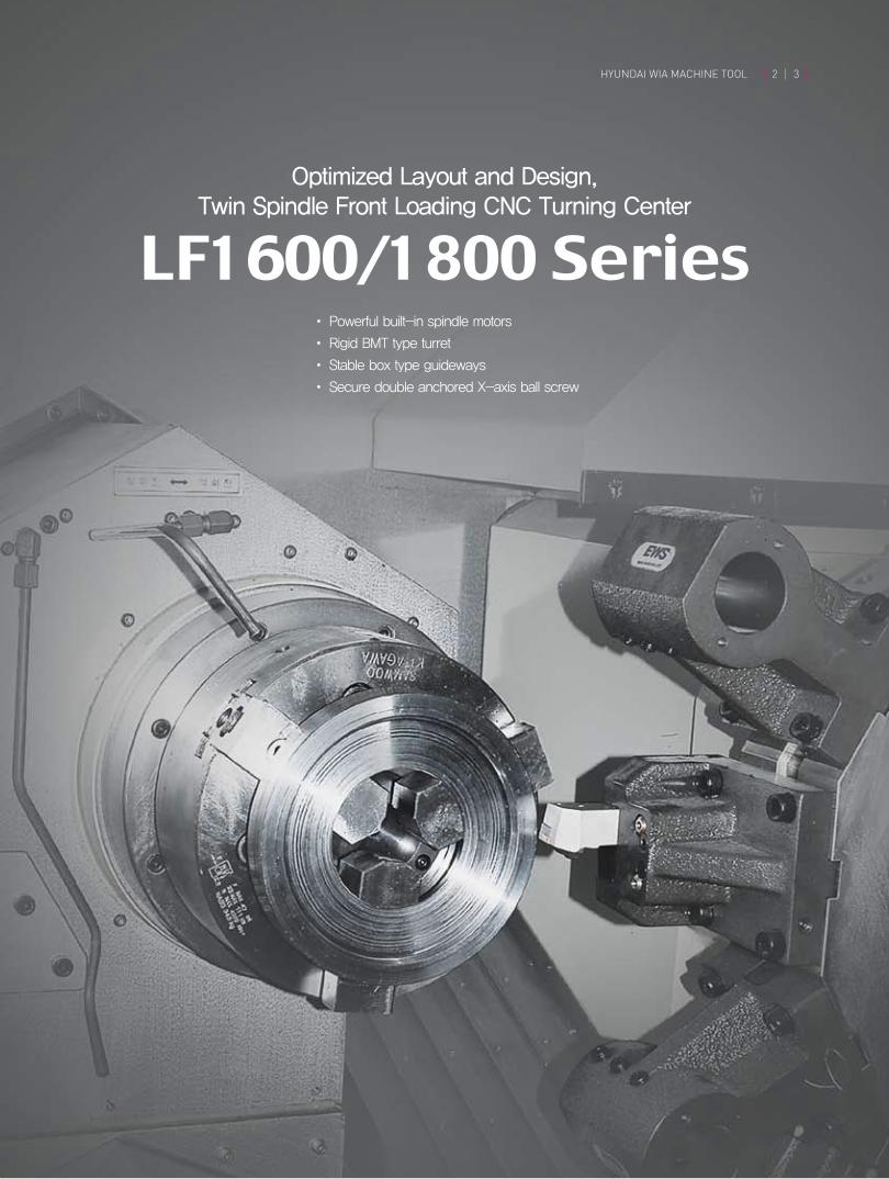
Optimized Layout and Design, Twin Spindle Front Loading CNC Turning Center
�•�Powerful�built-in�spindle�motors
•�Rigid�BMT�type�turret
•�Stable�box�type�guideways
•�Secure�double�anchored�X-axis�ball�screw
LF1600/1800 Series
HYUNDAI WIA MACHINE TOOL 2 3

BASIC STRUCTURETwin Spindle Front Loading Turning Center
The LF 1600/1800 Series utilizes box guideways for axial movement. Box guideways provide unsurpassed long-term rigidity and accuracy, even under the heaviest of cutting operations.
The double pretension design provides outstanding positioning and repeatability with virtually no thermal growth. The ball screw is connected directly to the servo drive motors without gears or belts, to eliminate backlash.
Adoption of Box guideway
Double anchor type ball screw
Powerful servo drives provide quick acceleration and improve productivity by reducing non-cutting time. This is further enhanced by the use of box guideways, adding a measure of rigidity
Powerful Servo Drives
The bed and hydraulic unit of LF1600/1800 Series machines is separated by design, to reduce vibration and minimize thermal growth in the castings. Disposal of lubricant is also more easily recovered.
Separated type of bed design
LF1600/2SP

Spindle Processing Flow
Spindle Torque & Power
Spindle
Power (kW)
64N.m (30min)120N.m (30min)
7.5kW (30min)
11kW (30min)47N.m (Cont.)81.4N.m (Cont.)
5.5kW (Cont.)7.5kW (Cont.)
Torque (kW) Power (kW) Torque (kW)
Spindle specification
Chuck�Size
Spindle�Bore
Spindle�Speed�(rpm)
Output�(Max./Cont.)
Torque�(Max./Cont.)
Spindle�Type
Spindle�Nose
C-axis�Indexing
inch
mm(in)
r/min
kW(HP)
N.m
-
-
deg
ITEM6″
Ø53 (2.1″)
4,500
7.5/5.5 (10/7)
64/47
BELT
A2-5
-
6″
Ø53 (2.1″)
4,500
7.5/5.5 (10/7)
64/47
BELT
A2-5
0.001°
8″
Ø63 (2.5″)
3,500
11/7.5 (15/10)
120/81.4
BELT
A2-6
-
8″
Ø63(2.5″)
3,500
11/7.5 (15/10)
120/81.4
BELT
A2-6
0.001°
LF1600 LF1600M LF1800 LF1800M
Parts requiring secondary operations are transferred from Z1 spindle to Z2 spindle via the Z1 spindle’s axis, allowing the secondary process to begin.
The same part can be machined simultaneously, utilizing both the spindle of Z1 axis and Z2 axis, doubling productivity in a single machine.
Multiple families of parts can also be machined simultaneously, utilizing both the spindle of Z1 axis and Z2 axis, doubling productivity in a single machine.
LF1600/2SP LF1800/2SP
HYUNDAI WIA MACHINE TOOL 4 5
By enlarging the spindle’s diameter and thickness, and using only verified bearings, its rigidity is increased significantly.
This contributes to improved durability and provides a high quality surface finish on every finished part.
Spindle structure
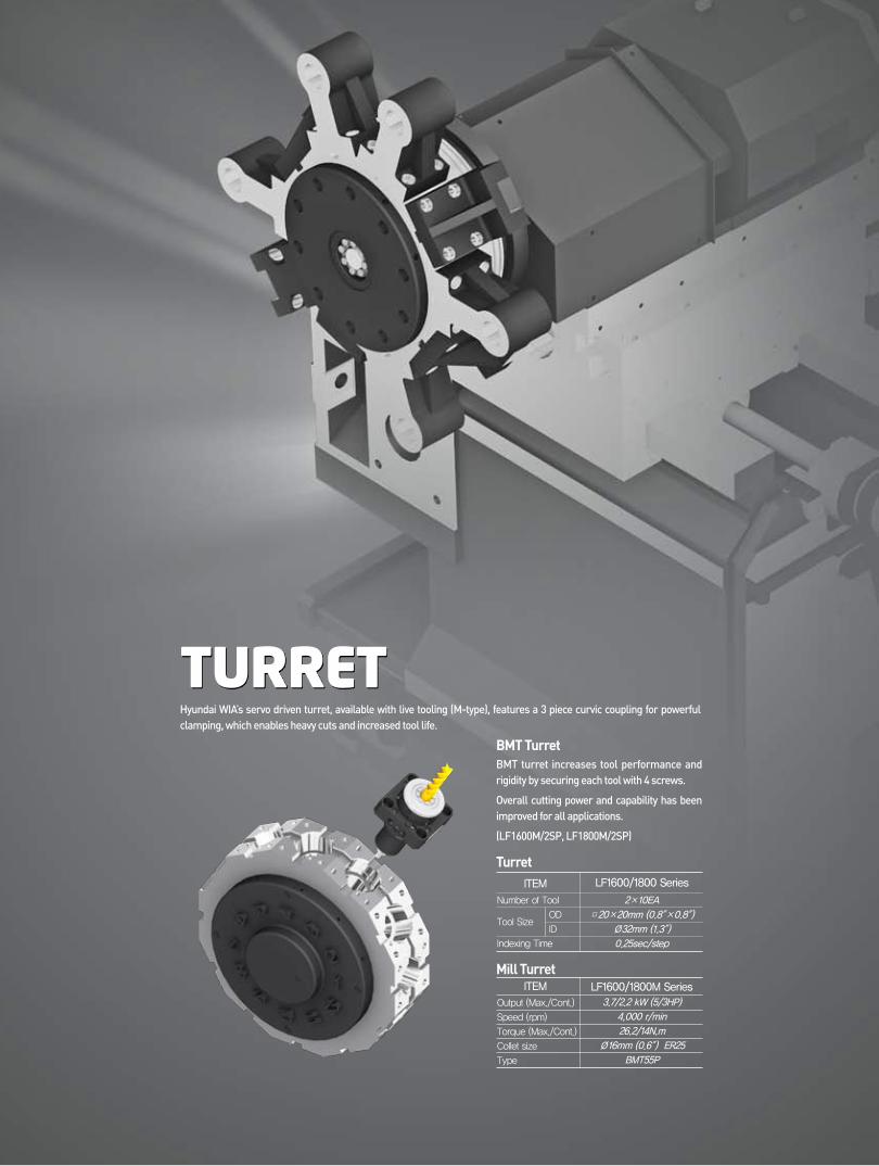
TURRET
BMT turret increases tool performance and rigidity by securing each tool with 4 screws.
Overall cutting power and capability has been improved for all applications.
(LF1600M/2SP, LF1800M/2SP)
Hyundai WIA’s servo driven turret, available with live tooling (M-type), features a 3 piece curvic coupling for powerful clamping, which enables heavy cuts and increased tool life.
BMT Turret
Number�of�Tool
Tool�Size�OD
� ID
Indexing�Time
2×10EA
□20×20mm (0.8″×0.8″)
Ø32mm (1.3″)
0.25sec/step
TurretITEM
ITEM
LF1600/1800 Series
LF1600/1800M Series
Output�(Max./Cont.)
Speed�(rpm)
Torque�(Max./Cont.)
Collet�size�
Type
3.7/2.2 kW (5/3HP)
4,000 r/min
26.2/14N.m
Ø16mm (0.6″) ER25
BMT55P
Mill Turret

Machining
Sample Workpieces
Machining Variation
O.D Cutting
I.D Cutting
End Milling
Drilling
Drilling
I.D Threading
Ball-End Milling
Face Milling
Milling Tool Holder
Angular Milling HeadStraight Milling Head
U-Drill
Collet&Cap
Endmill
Endmil
Drill
Tap
Drill
Tap
Face Cutter
HYUNDAI WIA MACHINE TOOL 6 7
Machining capabilities have been increased with the addition of a Straight Milling Head, which can remove material from the side of the workpiece, and an Angular Milling Head, which can perform I.D. operations.
A wide variety of additional tool holders can further enhance the machines with capabilities that include drilling and tapping, among others.
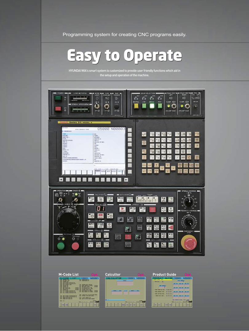
Easy to Operate
Programming system for creating CNC programs easily.
HYUNDAI WIA's smart system is customized to provide user friendly functions which aid in the setup and operation of the machine.
M-Code List Opt. Calcultor Opt. Product Guide Opt.

HYUNDAI WIA MACHINE TOOL 8 9
HW-PGi F Programming Guide i for Fanuc System
HW-TL : Torque LimiterBy sensing the contact load amount on the machine, the torque limiter retracts immediately upon tool impact, to minimize damage to the machine
HW-TM : Tool Monitoring System Opt.
HW-TM
Torque Limiter Diagram
Realistic 3D solid animationPrograming is simulated
Example of easy programmingReadily programing with interactive type, without code
Engraving CycleEngraving Programs are instantly created
by entering the required text.
❖�When�you�order�these�options,�Please�contact�sales�man
• Real-time cut monitoring• 2 Channel screen display • Self learning for machining amount • 3 stage of status monitoring
(wear/break/no-load)
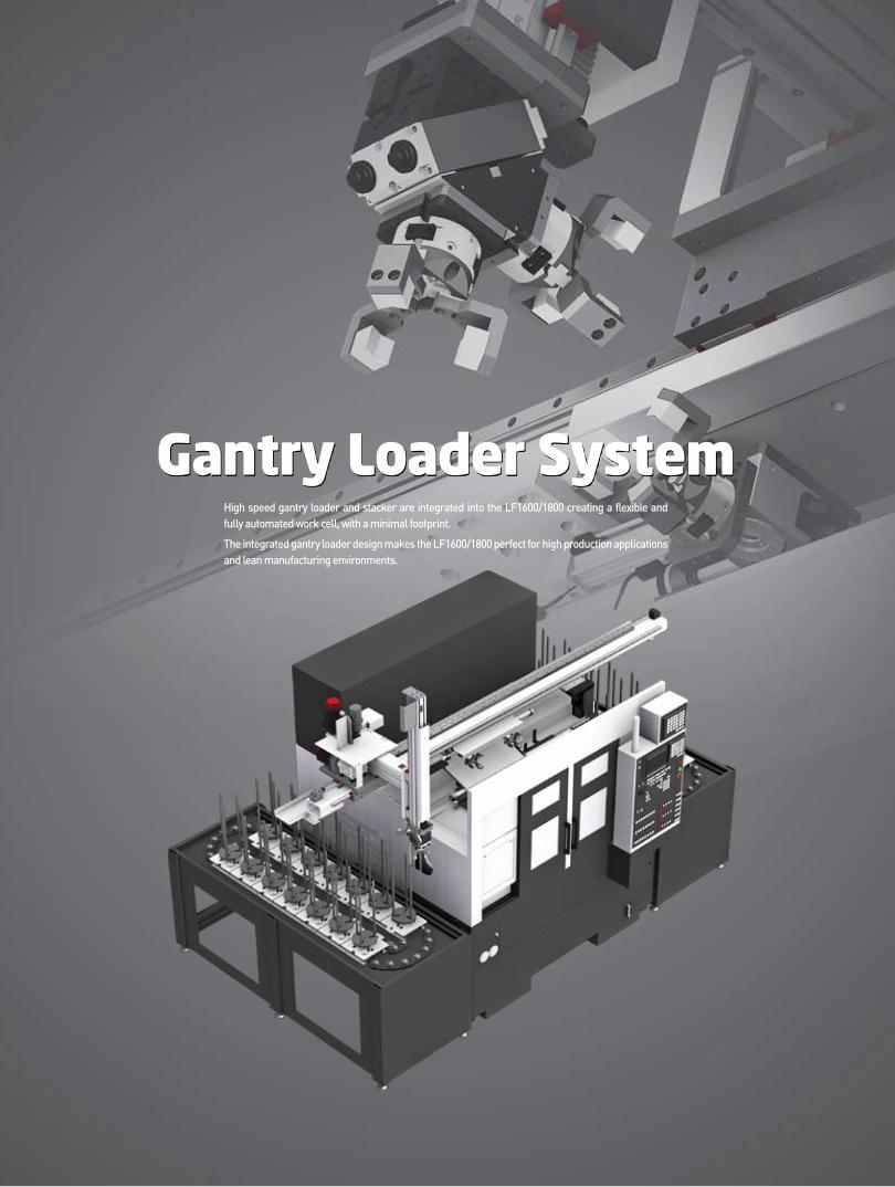
Gantry Loader SystemHigh speed gantry loader and stacker are integrated into the LF1600/1800 creating a flexible and fully automated work cell, with a minimal footprint.
The integrated gantry loader design makes the LF1600/1800 perfect for high production applications and lean manufacturing environments.
HYUNDAI WIA MACHINE TOOL 10 11
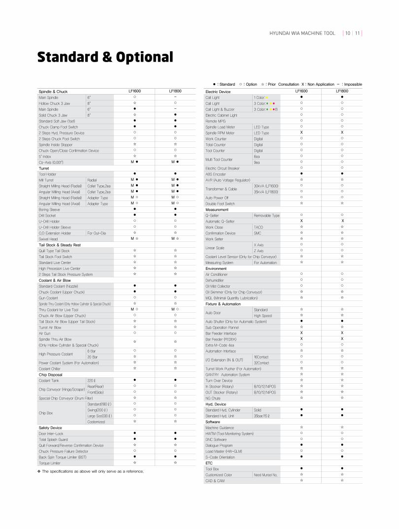
Standard & Optional
Call Light
Call Light
Call Light & Buzzer
Electric Cabinet Light
Remote MPG
Spindle Load Meter
Spindle RPM Meter
Work Counter
Total Counter
Tool Counter
Multi Tool Counter
Electric Circuit Breaker
ABS Encoder
AVR (Auto Voltage Regulator)
Transformer & Cable
Auto Power Off
Double Foot Switch
Measurement
Q-Setter
Automatic Q-Setter
Work Close
Confirmation Device
Work Setter
Linear Scale
Coolant Level Sensor (Only for Chip Conveyor)
Measuring System
Environment
Air Conditioner
Dehumidifier
Oil Mist Collector
Oil Skimmer (Only for Chip Conveyor)
MQL (Minimal Quantity Lubrication)
Fixture & Automation
Auto Door
Auto Shutter (Only for Automatic System)
Sub Operation Pannel
Bar Feeder Interface
Bar Feeder (FEDEK)
Extra M-Code 4ea
Automation Interface
I/O Extension (IN & OUT)
Turret Work Pusher (For Automation)
GANTRY Automation System
Turn Over Device
In Stocker (Rotary)
OUT Stocker (Rotary)
NG Chute
Hyd. Device
Standard Hyd. Cylinder
Standard Hyd. Unit
Software
Machine Guidance
HWTM (Tool Monitoring System)
DNC Software
Dialogue Program
Load Master (HW-GLM)
S-Code Orientation
ETC
Tool Box
Customized Color
CAD & CAM
❖�The�specifications�as�above�will�only�serve�as�a�reference.
LF1600 LF1800
● ●
○ ○
○ ○
○ ○
○ ○
○ ○
X X
○ ○
○ ○
○ ○
○ ○
○ ○
○ ○
● ●
☆ ☆
○ ○
○ ○
○ ○
☆ ☆
○ ○
X X
☆ ☆
☆ ☆
☆ ☆
○ ○
○ ○
☆ ☆
☆ ☆
○ ○
○ ○
○ ○
☆ ☆
☆ ☆
☆ ☆
☆ ☆
● ●
☆ ☆
X X
X X
○ ○
☆ ☆
○ ○
○ ○
☆ ☆
☆ ☆
☆ ☆
☆ ☆
☆ ☆
☆ ☆
● ●
● ●
☆ ☆
○ ○
○ ○
● ●
○ ○
● ●
● ●
☆ ☆
☆ ☆
Electric Device
Main Spindle
Hollow Chuck 3 Jaw
Main Spindle
Solid Chuck 3 Jaw
Standard Soft Jaw (1set)
Chuck Clamp Foot Switch
2 Steps Hyd, Pressure Device
2 Steps Chuck Foot Switch
Spindle Inside Stopper
Chuck Open/Close Confirmation Device
5° Index
Cs-Axis (0.001°)
Turret
Tool Holder
Mill Turret
Straight Milling Head (Radial)
Angular Milling Head (Axial)
Straight Milling Head (Radial)
Angular Milling Head (Axial)
Boring Sleeve
Drill Socket
U-Drill Holder
U-Drill Holder Sleeve
O.D Extension Holder
Swivel Head
Tail Stock & Steady Rest
Quill Type Tail Stock
Tail Stock Foot Switch
Standard Live Center
High Precesion Live Center
2 Steps Tail Stock Pressure System
Coolant & Air Blow
Standard Coolant (Nozzle)
Chuck Coolant (Upper Chuck)
Gun Coolant
Spindle Thru Coolant (Only Hollow Cylinder & Special Chuck)
Thru Coolant for Live Tool
Chuck Air Blow (Upper Chuck)
Tail Stock Air Blow (Upper Tail Stock)
Turret Air Blow
Air Gun
Spindle Thru Air Blow
(Only Hollow Cylinder & Special Chuck)
High Pressure Coolant
Power Coolant System (For Automation)
Coolant Chiller
Chip Disposal
Coolant Tank
Chip Conveyor (Hinge/Scraper)
Special Chip Conveyor (Drum Filter)
Chip Box
Safety Device
Door Inter-Lock
Total Splash Guard
Quill Forward/Reverse Confirmation Device
Chuck Pressure Failure Detector
Back Spin Torque Limiter (BST)
Torque Limiter
6″
8″
6″
8″
Radial
Collet Type,2ea
Collet Type,2ea
Adapter Type
Adapter Type
For Out-Dia
6 Bar
20 Bar
220ℓ
Rear(Rear)
Front(Side)
Standard(180ℓ)
Swing(200ℓ)
Large Size(330ℓ)
Costomized
1 Color:■
3 Color:■■■
3 Color:■■■B
LED Type
LED Type
Digital
Digital
Digital
6ea
9ea
30kVA (LF1600)
35kVA (LF1800)
Removable Type
TACO
SMC
X Axis
Z Axis
For Automation
Standard
High Speed
16Contact
32Contact
8/10/12/14POS
8/10/12/14POS
Solid
35bar/15ℓ
Need Munsel No.
LF1600 LF1800
○ –
☆ ○
● –
☆ ●
● ●
● ●
○ ○
○ ○
☆ ☆
○ ○
☆ ☆
M ● M ●
● ●
M ● M ●
M ● M ●
M ● M ●
M ○ M ○
M ○ M ○
● ●
● ●
○ ○
○ ○
☆ ☆
M ☆ M ☆
☆ ☆
☆ ☆
☆ ☆
☆ ☆
☆ ☆
● ●
● ●
○ ○
☆ ☆
M ○ M ○
○ ○
☆ ☆
☆ ☆
○ ○
☆ ☆
○ ○
☆ ☆
☆ ☆
☆ ☆
● ●
○ ○
○ ○
☆ ☆
○ ○
○ ○
○ ○
☆ ☆
● ●
● ●
☆ ☆
○ ○
● ●
☆ ☆
Spindle & Chuck
● : Standard ○ : Option ☆ : Prior Consultation X : Non Application - : Impossible
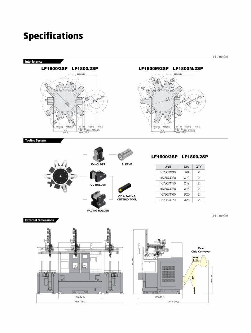
Specifications
unit : mm(in)
Interference
Tooling System
LF1600/2SP LF1800/2SP
LF1600/2SP LF1800/2SP
LF1600M/2SP LF1800M/2SP360 (14.2)
135 (5.3) 135 (5.3) 65(2.5)
30(1.2)
130(5.1)
140(5.5)
95(3.7)
270(10.6)
10(0.4)
95 (3.7)95 (3.7)
95 (3
.7)
95 (3
.7)
ø188(7.4) ø188
(7.4)
ø180(7.1) ø186
(7.3)
ø193
(7.6) ø186
(7.3)
ø530(20.8)
360 (14.2)
135 (5.3) 135 (5.3) 65(2.5)
30(1.2)
130(5.1)
140(5.5)
95(3.7)
270(10.6)
10(0.4)
ø530
(20.8)
ø260
(10.2)ø165(6.5)
ø165
(6.5)ø165
(6.5)
ID HOLDER SLEEVE
OD & FACINGCUTTING TOOL
OD HOLDER
FACING HOLDER
UNIT
1678674210
1678674220
1678674150
1678674230
1678674160
1678674170
DIA
Ø8
Ø10
Ø12
Ø16
Ø20
Ø25
QTY
2
2
2
2
2
2
unit : mm(in)
External Dimensions
RearChip Conveyor
1900(74.8)
3814(150.1)
1936(76.2)
2782
(109
.5)
1200
(47.
2)
3054(120.2)
unit : mm(in)
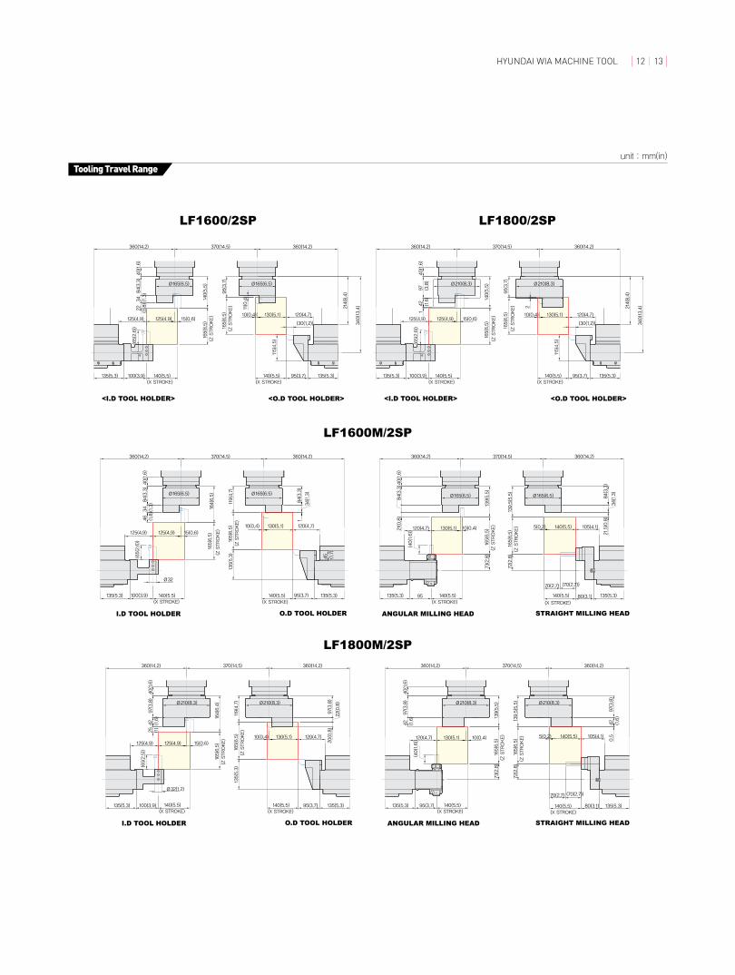
Tooling Travel Range
95(3.7)
360(14.2)
140(5.5)(X STROKE)
360(14.2)
140(5.5)(X STROKE)
15(0.6)
100(3.9)
370(14.5)
40(1.6)
97(3.8)
164(6.4)
165(6.5)
(Z STROKE)
125(4.9)125(4.9)
119(4.7)
165(6.5)
(Z STROKE)
10(0.4) 130(5.1)
25 (1)
120(4.7)
135(5.3)
I.D TOOL HOLDER O.D TOOL HOLDER
135(5.3)
97(3.8)
22(0.8)
(65(2.5))
135(5.3)80(3.1)
70(2.7) (70(2.7))
140(5.5)(X STROKE)
72(2.8)
135(5.3) 95(3.7)
73(2.8)
140(5.5)(X STROKE)
165(6.5)
(Z STROKE)
ANGULAR MILLING HEAD STRAIGHT MILLING HEAD
360(14.2)360(14.2) 370(14.5)
40(1.6)
97(3.8)
Ø32(1.2)
42(1.6)
10(0.4)130(5.1)120(4.7)
139.5(5.5)
165(6.5)
(Z STROKE) 5(0.2) 140(5.5) 105(4.1)
42(1.6)
0.5
135(5.3)
42(1.6) 139(5.5)
20(0.8)
97(3.8)
Ø210(8.3) Ø210(8.3) Ø210(8.3) Ø210(8.3)
(40(1.6))
(X STROKE)(X STROKE)
40(1.6)
84(3.3)
164(6.5)
(Z STROKE)
119(4.7)
(Z STROKE)46(1.8)
I.D TOOL HOLDER O.D TOOL HOLDER
135(5.3)
84(3.3)
34(1.3)
45(1.7)
80(3.1)
70(2.7) (70(2.7))
(X STROKE)
72(2.8)
Ø165(6.5)
95
73(2.8)
(X STROKE)
165(6.5)
(Z STROKE)
ANGULAR MILLING HEAD STRAIGHT MILLING HEAD
40(1.6)
84(3.3)
21(0.8)
Ø32
34(1.3)
10(0.4)130(5.1)120(4.7)
139.5(5.5)
165(6.5)
(Z STROKE) 5(0.2) 140(5.5) 105(4.1)
34(1.3)
21.5(0.8)
Ø165(6.5)
139(5.5)
1
84(3.3)
(40(1.6))
95(3.7)
360(14.2)
140(5.5)(X STROKE)
360(14.2)
140(5.5)(X STROKE)
15(0.6)
100(3.9)
Ø165(6.5)
370(14.5)
40(1.6)
84(3.3)
34(1.3)
140(5.5)
165(6.5)
(Z STROKE)
125(4.9)125(4.9)
95(3.7)
165(6.5)
(Z STROKE)
10(0.4) 130(5.1)
11(0.4)
22 (0.8)
120(4.7)
135(5.3)135(5.3) 95(3.7)140(5.5)(X STROKE)
140(5.5)(X STROKE)
100(3.9) 135(5.3)135(5.3)
Ø165(6.5)
<I.D TOOL HOLDER> <O.D TOOL HOLDER>
340(13.4)
115(4.5)
214(8.4)
(65(2.6))
95(3.7)
360(14.2)
140(5.5)
360(14.2)
140(5.5)
15(0.6)
100(3.9)
Ø165(6.5)
370(14.5) 360(14.2)360(14.2) 370(14.5)
165(6.5)
165(6.5)
125(4.9)125(4.9)
10(0.4) 130(5.1) 120(4.7)
135(5.3)140(5.5) 135(5.3) 135(5.3)140(5.5)135(5.3)
Ø165(6.5)
(65(2.6))
360(14.2)360(14.2)
15(0.6)
370(14.5)
140(5.5)
165(6.5)
125(4.9)125(4.9)
95(3.7)
165(6.5)
(65(2.6))
(30(1.2))
10(0.4) 130(5.1) 120(4.7)
340(13.4)
115(4.5)
214(8.4)
(30(1.2))
Ø210(8.3)
40(1.6)
97(3.8)
42(1.6)
(Z STROKE)
(Z STROKE) 2
1
Ø210(8.3)
<I.D TOOL HOLDER> <O.D TOOL HOLDER>
LF1600/2SP LF1800/2SP
LF1600M/2SP
LF1800M/2SP
HYUNDAI WIA MACHINE TOOL 12 13

Specifications
LF1600/2SP LF1600M/2SP LF1800/2SP LF1800M/2SP� � � � Ø370�(14.6″)�
� � � � Ø370�(14.6″)�
� � � � Ø260�(10.2″)�
� � 165�(6.5″)� � � � 155�(6.1″)�
� � Ø45�(1.77″)� � � � ø52�(2″)
� � ø165�(6.5″)� � � � ø210�(8.3″)
� � ø53�(2.1″)� � � � ø63�(2.5″)
� � 4,500� � � � 3,500
� � 7.5/5.5�(10/7.4)� � � � 11/7.5�(15/10)
� � 64/47� � � � 120/81.4
� � � � BELT
� � A2-5� � � � A2-6
� -� � 0.001˚� � -� � 0.001˚
� � � � 140/165�(5.5″/6.5″)�
� � � � 24/24�
� � � � BOX�GUIDE
� � � � 2×10
� � � � □20×20�(0.8″×0.8″)
� � � � ø32�(1.3″)
� � � � 0.25�
� -� � 3.7/2.2�(5/3)� � -� � 3.7/2.2�(5/3)
� -� � 4,000� � -� � 4,000
� -� � 26.2/14� � -� � 26.2/14
� -� � Ø16�(0.6″)�ER25� � -� � Ø16�(0.6″)�ER25
� -� � BMT55P� � -� � BMT55P
� � � � 220�(58.1)�
� � � � 4�(1)�
� � 25� � � � 30�
� � � � Over�25�
� � � � 220/60�(200/50)
1,900×1,936�(74.8″×76.2″)
� 2,210�(87″)
� � � � 4,500�(9,921)
� � � � FANUC�31i�Series
CAPACITY
Swing�Over�the�Bed�
Swing�Over�the�Carriage
Max.�Turning�Dia.�
Max.�Turning�Length
Bar�Capacity
Chuck�Size�
Spindle�Bore
Spindle�Speed�(rpm)
Motor�(Max/Cont.)
Torque�(Max/Cont.)
Spindle�Type
Spindle�Nose
C-axis�Indexing�
Travel�(X/Z/B)
Rapid�Travel�(X/Z/B)�
Slide�Type��
No.�of�Tool�
Tool�Size��� OD
� �� ID
Indexing�Time�
Motor�(Max/Cont.)�
Milling�Tool�Speed�(rpm)�
Touque�(Max/Cont.)�
Collet�Size�
Type�
Coolant�Tank�
Lubricating�Tank�
Electric�Power�Supply�
Thickness�of�Power�Cable
Voltage�
Floor�Space�(L×W)�
Height�
Weight�
Controller
FEED
TANkCAPACITY
LIvE TOOL
SPIndle
TURRET
MACHINE
NC
POWERSUPPLY
❖�Specifications�are�subject�to�change�for�improvement�without�notice.
mm(in)
mm(in)
mm(in)
mm(in)
mm(in)
mm(in)
mm(in)
r/min
kW(HP)
N.m
-
-
deg
mm(in)
m/min
-
EA
mm(in)
mm(in)
sec/step
kW(HP)
r/min
N.m
mm(in)
-
ℓ(gel)
ℓ(gel)
kVA
Sq
V/Hz
mm(in)
mm(in)
kg(lb)
-
ITEM
Specifications
[������]�:�Option

Controller
FANUC 31i Series
Max. 4 axes are available
TTSY : X1, Z1, Y1, C1, X2, Z2, B2, C2
TTMS : X1, Z1, C1, X2, Z2, B2, C2
TTM : X1, Z1, C1, X2, Z2
TTS : X1, Z1, X2, Z2, B2
TT : X1, Z1, X2, Z2
2axes / Linear & circular (Max. 4 axes)
X, Z, Y, B axes : 0.001 mm (0.0001″)
C, A axes : 0.001 deg
X, Z, Y, B axes : 0.001 mm (0.0001″)
C, A axes : 0.001 deg
G20 / G21
Each axis / All axes
All axes
Over-travel
+/- 0~9999 pulses
(Rapid traverse & cutting feed)
Back-spin torque limiter (BST)
10.4″Color LCD
Sequence, Program
Dry run., program check
Rapid, Jog, Handle
x1, x10, x100
F code feedrate direct command
0~200 % (10% units)
0~2,000 mm/min[79 ipm]
F0, F5, F25 / F50, F100%
Positioning / Linear / Circular
(G00/G01/G02, G03)
G04, 0~9999.9999 sec
Controlled�axes
Simultaneous�controllable�axes
Least�input�increment
Least�command�increment
High�speed�HRV�control
Inch�/�Metric�conversion
Interlock
Machine�lock
Emergency�stop
Stored�stroke�check�1
Stored�stroke�check�2
Stored�stroke�check�3
Follow-up
Servo-off
Backlash�compensation
Position�switch
Unexpected�disturbance�torque�
detection
(HRM)�control�
LCD�/�MDI
Operation
Automatic�operation�(memory)
MDI�operation
Search�function
Program�restart
Wrong�operation�prevention
Buffer�register
Program�check�function
Single�block
Feed functions
Manual�jog�feed�
Manual�handle�feedrate
Feed�command
Feedrate�override
Jog�override
Rapid�traverse�override
Override�cancel
Feed�per�minute,�feed�per�rotation
Nano�interpolation
Dwell
Thread�retract
Variable�lead�threading
G28, manual
G27
G30
M00, M01 / M02, M30
EIA / ISO
1 EA
+/- 9999.9999”
O4 digits
G17, G18, G19
G52 to G59
“ON” fixed
Included chamfering / Corner R`
A
G10
10 folds nested
#100 to #199, #500 to #999
Conversational programming
M4 digits
S4 digits, binary output
50% to 150% (10% units)
T2 + 2
64 pairs
G40, G41, G42
RS232C
100 Mbps
256 Kbyte
Max. 500 programs
Copy / Move / Change of NC program
1st�reference�point�return
Reference�point�return�check
2nd�reference�point�return
Program�Stop�/�End
Tape�code
Optional�block�skip
Maximum�programmable�
dimensions
Program�number
Absolute�and�incremental�
programming
Decimal�point�input
Plane�selection
Work�coordinate�system�selection
Manual�absolute
Direct�drawing�dimension�program
G�code�system
Programmable�data�input�
Sub�program�call
Custom�macro�B
Addition�of�custom�macro�common�
variable
Multiple�repetitive�cycles�/�Ⅱ
Canned�cycles�for�turning
Manual�guide�i
Miscellaneous�function
Miscellaneous�function�lock
Spindle�speed�command
Constant�surface�speed�control
Spindle�speed�override
Spindle�orientation�
Rigid�tapping
Tool�function
Tool�offset�pairs
Tool�offset�
Tool�nose�radius�compensation
Geometry�/�Wear�compensation
Direct�input�of�measured�tool�
compensation�value�B
Tool�life�management
Reader�/�Puncher�interface
Memory�card�input/output
Embedded�ethernet
Part�program�storage�length
No.�of�registrable�programs�
expansion
Memory�lock
Background�editing
Extended�part�program�edition
Alarm & operation display
Load meter, etc
Screen saver
Turn mill
Turn mill
Turn mill
Turn mill
Turn mill
Turn mill, Sub spindle
Sub spindle
Sub spindle
Y type machine
Y type machine (Except L210/250SY)
LF series with Loader
LF series with Loader
LF series with Loader
100 Mbps (Option board is required)
9 EA
B / C
512 Kbyte / 1024 Kbyte
99 / 200 / 400 pairs
HWTM (Built-in Fanuc type)
Self-diagnosis�function
History�display
Help�function
External�message
Run�hour�/�Parts�count�display
Display�of�actual�spindle�speed�
and�T�code
Actual�cutting�feedrate�display
Operating�monitor�screen
Graphic�display
Spindle�/�Servo�setting�screen
Selection�of�5�optional�language
Erase�CRT�screen�display
Automatic�data�backup
Cs�contouring�control
Stored�pitch�error�compensation
Polar�coordinate�interpolation
Cylindrical�interpolation
Canned�cycles�for�drilling
Spindle�orientation�expansion
Spindle�synchronous�control
Torque�control
Y�axis�offset
Angular�axis�control
Macro�executor
Playback
Loader�master
(Loader�set-up�program)
Options
Fast�ethernet
Optional�block�skip
3rd��and�4th��reference�point�return
G�code�system
Part�program�storage�length
Tool�offset�pairs
Polygon�turning
Helical�interpolation
Dynamic�graphic�display
Protection�of�data�at�8�levels
Tool�Monitoring�function
Axis control / Display unit Program input & interpolation functions Display, diagnosis & setting functions
Auxiliary / Spindle speed functions
Tool function / Tool compensation
Data in/output & editing functions
Functions according to machine specification
•Figures�in�inch�are�converted�from�metric�values.��������
•Design�and�specifications�subject�to�change�without�notice.
Program input & interpolation functions