l · Web viewaccipiō, accipere, accēpī, acceptum agō, agere, ēgī, āctum
date post
18-Dec-2015Category
view
218download
0
2002 Partial Implications, etc. 1
Using Partial Implications for Redundancy Identification and
Fault Equivalence
Vishwani D. AgrawalAgere Systems, Murray Hill, New Jersey
[email protected]://cm.bell-labs.com/cm/cs/who/va

2002 Partial Implications, etc. 2
Talk Outline
•Problem statement
•Background
•Implication graph
•Partial implications
•Transitive closure
•Redundancy identification
•A new method for fault equivalence
•Conclusion
2002 Partial Implications, etc. 3
Problem Statement
•Many problems can be solved by implication graphs and transitive closure.
•We will study two problems:•Redundancy identification
•Fault equivalence
2002 Partial Implications, etc. 4
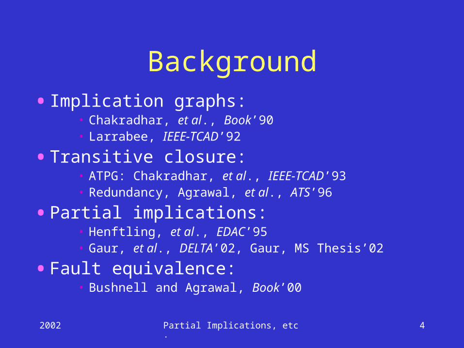
Background•Implication graphs:
• Chakradhar, et al., Book’90• Larrabee, IEEE-TCAD’92
•Transitive closure:• ATPG: Chakradhar, et al., IEEE-TCAD’93• Redundancy, Agrawal, et al., ATS’96
•Partial implications:• Henftling, et al., EDAC’95• Gaur, et al., DELTA’02, Gaur, MS Thesis’02
•Fault equivalence:• Bushnell and Agrawal, Book’00

2002 Partial Implications, etc. 5
Implication graph
•Nodes• Two nodes per signal; nodes a and a correspond
to signal a.• A node has two states (true,false); represents the
signal state.
•Edges• A directed edge from node a to b means “a=1”
implies “b=1”.
An implication graph is a representation of logical implications between pairs of signals of a digital circuit.
2002 Partial Implications, etc. 6
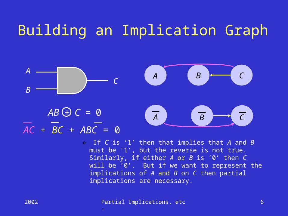
Building an Implication Graph
» If C is ‘1’ then that implies that A and B must be ‘1’, but the reverse is not true. Similarly, if either A or B is ‘0’ then C will be ‘0’. But if we want to represent the implications of A and B on C then partial implications are necessary.
AC + BC + ABC = 0
A
BC
AB + C = 0
A B C
A B C

2002 Partial Implications, etc. 7
Partial Implications
•
AC + BC + ABC = 0
A
BC
AB + C = 0
A B C
A B C
Reference: Henftling, et al., EDAC, 1995

2002 Partial Implications, etc. 8
Observability Variables
Observability variable of a signal represents whether or not that signal is observable at a PO. It can be true or false.
A
BC
OCOA + BOA + OCBOA = 0
B
OCB + OA = 0
OB
OA OC = 1
(PO)
OA
OC
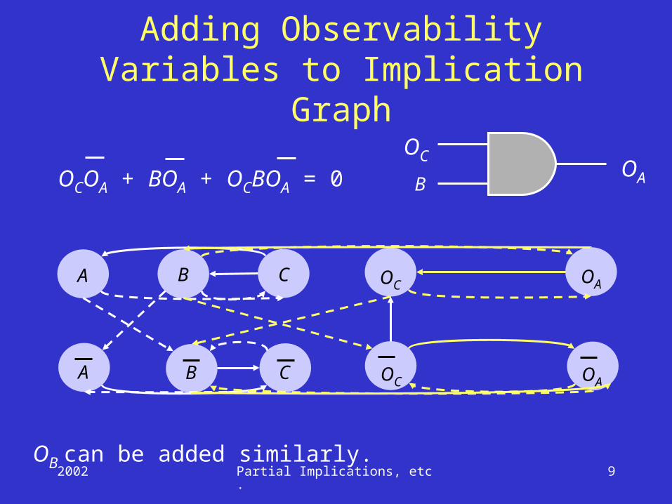
2002 Partial Implications, etc. 9
Adding Observability Variables to Implication Graph
A B C
A B C
OCOA + BOA + OCBOA = 0 BOA
OC
OC OA
OC OA
OB can be added similarly.

2002 Partial Implications, etc. 10
Transitive Closure•Transitive closure of a directed graph
contains the same set of nodes as the original graph.
•If there is a directed path from node a to b, then the transitive closure contains an edge from a to b.
ab
c
ab
cd d
A graph Transitive closure
2002 Partial Implications, etc. 11
Stuck-at Faults
• This is a type of fault, which causes a line to hold a constant logic value, irrespective of change of state at previous stages.
• There are two types of stuck-at-faults:• Stuck-at-1• Stuck-at-0
• Detection of a fault requires the fault to be activated and its effect observable at a PO.
• Fault a s-a-1 is detectable, iff following conditions can be simultaneously satisfied:• a = 0
• Oa = 1
2002 Partial Implications, etc. 12
Redundant Faults
•A fault that has no test is called an untestable fault.
•Any untestable fault in a combinational circuit is a redundant fault because it does not cause any change in the input/output logic function of the circuit.
•Identification of redundant faults is useful because they can be removed
• from testing consideration, or• from hardware
2002 Partial Implications, etc. 13
Redundancy Identification•ATPG based method
• It uses exhaustive test pattern generation to determine whether or not a target fault has a test.
• All redundant faults can be found, but the ATPG cost is high (exponential in circuit size).
•Fault independent method• This method analyzes circuit topology and
function locally without targeting a specific fault.
• Many (not all) redundant faults can be found at a lower cost.

2002 Partial Implications, etc. 14
Redundancy Identification by Transitive Closure
a
b
c
d
e
s-a-0
s-a-0
a b cd
OcOd
Implication graph (some nodesand edges not shown)
Circuit with tworedundant faults
ImplicationPartial implicationTransitive closure edge
2002 Partial Implications, etc. 15
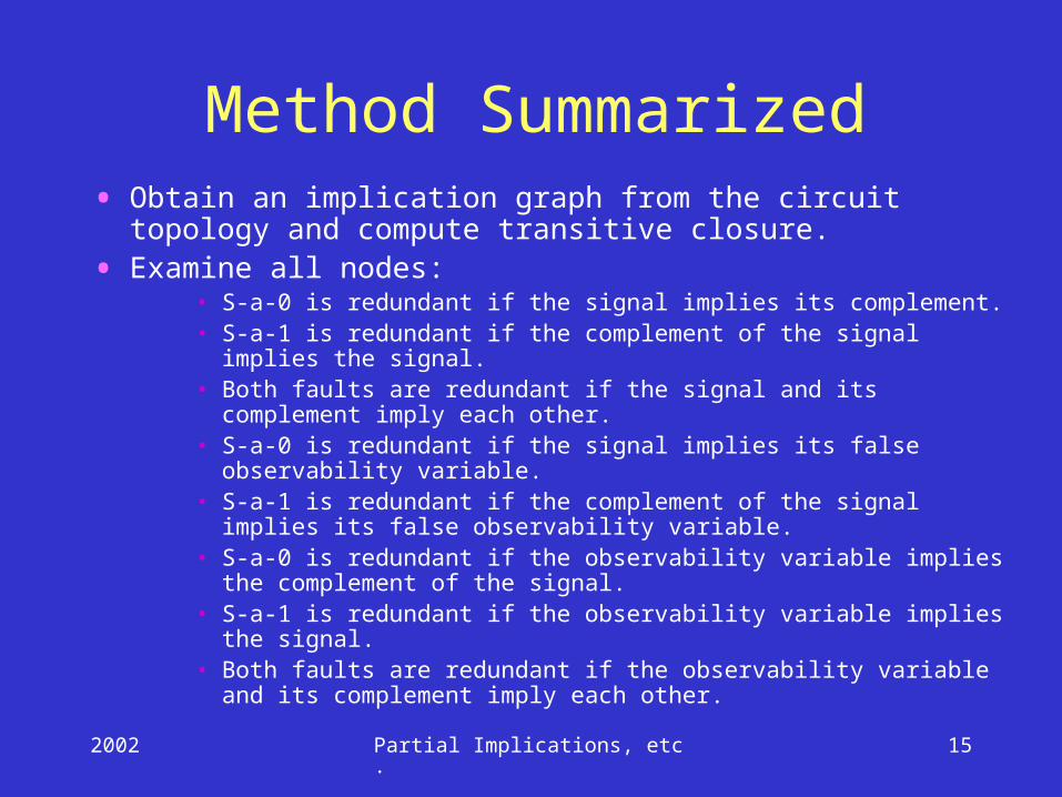
Method Summarized• Obtain an implication graph from the circuit topology and
compute transitive closure.
• Examine all nodes:• S-a-0 is redundant if the signal implies its complement.• S-a-1 is redundant if the complement of the signal implies the
signal.• Both faults are redundant if the signal and its complement imply
each other.• S-a-0 is redundant if the signal implies its false observability
variable.• S-a-1 is redundant if the complement of the signal implies its false
observability variable.• S-a-0 is redundant if the observability variable implies the
complement of the signal.• S-a-1 is redundant if the observability variable implies the signal.• Both faults are redundant if the observability variable and its
complement imply each other.
2002 Partial Implications, etc. 16
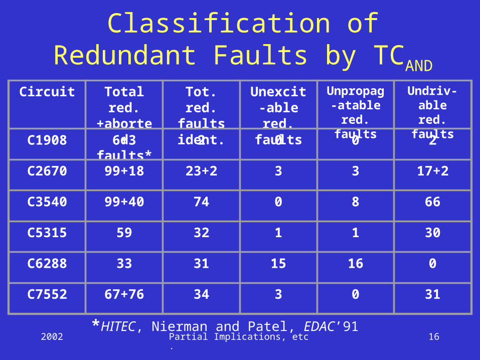
Classification of Redundant Faults by TCAND
Circuit Total red.+aborted
faults*
Tot. red. faults ident.
Unexcit-able red.
faults
Unpropag-atable red.
faults
Undriv-able red.
faults
C1908 6+3 2 0 0 2
C2670 99+18 23+2 3 3 17+2
C3540 99+40 74 0 8 66
C5315 59 32 1 1 30
C6288 33 31 15 16 0
C7552 67+76 34 3 0 31
*HITEC, Nierman and Patel, EDAC’91
2002 Partial Implications, etc. 17
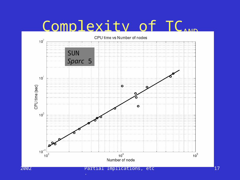
Complexity of TCAND
SUNSparc 5

2002 Partial Implications, etc. 18
Limitation of Method•Observability variable of a fanout stem is
not analyzed.
•Only the redundant faults due to false controllability of fanout stem can be identified.
s-a-0Three redundant s-a-0faults identified bytransitive closure
s-a-1
Two redundantstem faults not identifiedby transitive closure
2002 Partial Implications, etc. 19
Some Conclusions• Partial implications help find more redundant
faults than the transitive closure without partial implications.
• The results have been compared with FIRE (another fault-independent program), which did equal to or worse that transitive closure with partial implication.
• Transitive closure computation run times were linear in the number of nodes for the implication graphs of benchmark circuits, although the known worst-case complexity is O(N3) for N nodes.
2002 Partial Implications, etc. 20
Fault Equivalence• Two faults of a Boolean circuit are called
equivalent if they transform the circuit such that the two faulty circuits have identical output functions.
• Equivalent faults are indistinguishable and have exactly the same set of tests.
• Many fault equivalences can be determined by structural analysis based on gate fault equivalences and circuit interconnects; this is done in practice.
• Some fault equivalences require equivalence checking of faulty circuits; too complex and not generally done.
2002 Partial Implications, etc. 21
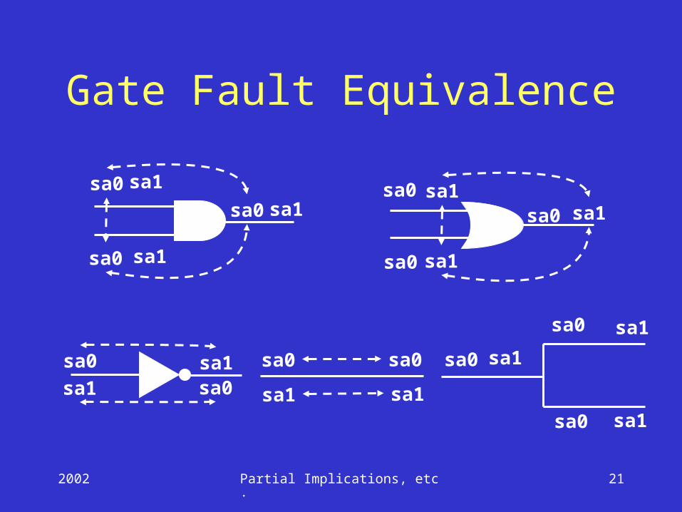
Gate Fault Equivalence
sa0
sa0
sa0 sa1
sa1
sa1
sa0
sa0
sa0
sa1
sa1
sa1
sa0
sa0sa1sa1 sa0sa0
sa1sa1
sa0
sa0
sa0
sa1
sa1
sa1
2002 Partial Implications, etc. 22
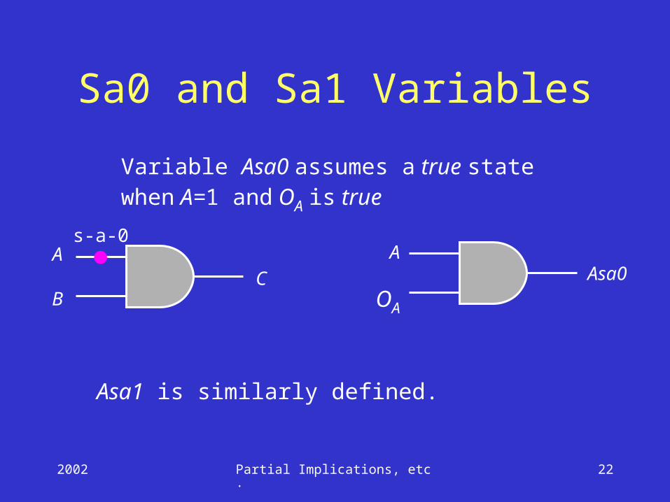
Sa0 and Sa1 Variables
A
BC
OA
AAsa0
s-a-0
Variable Asa0 assumes a true statewhen A=1 and OA is true
Asa1 is similarly defined.
2002 Partial Implications, etc. 23
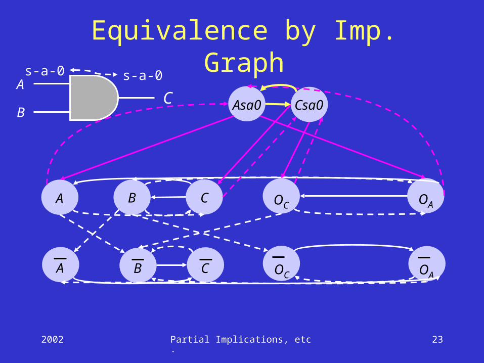
Equivalence by Imp. Graph
A B C
A B C
BC
A
OC OA
OC OA
Asa0 Csa0
s-a-0 s-a-0
2002 Partial Implications, etc. 24
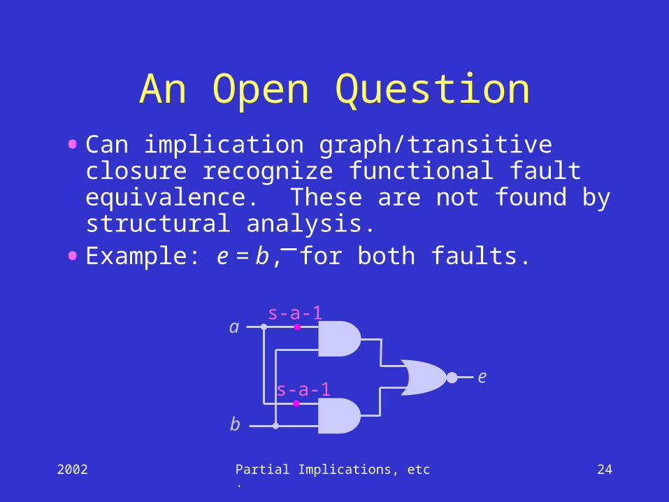
An Open Question•Can implication graph/transitive closure
recognize functional fault equivalence. These are not found by structural analysis.
•Example: e = b, for both faults.
a
b
e
s-a-1
s-a-1
2002 Partial Implications, etc. 25
Conclusion
•Partial implications improve redundancy identification.
•Present limitation of the method is the identification of redundancy due to the false observability of fanout stem; open problem.
•New formulation of fault equivalence may find some functional equivalences.
2002 Partial Implications, etc. 26
THANK YOU