2011 Dodge Ram Longhorn brought to you by your Mid Atlantic Dodge Ram dealer
INTRODUCTION
DODGE RAM 68RFE
No part of any ATSG publication may be reproduced, stored in any retrieval system or transmitted in any form or by any means, including but not limited to electronic, mechanical, photocopying, recording or otherwise, without written permission of Automatic Transmission Service Group. This includes all text illustrations, tables and charts.
The information and part numbers contained in this booklet havebeen carefully compiled from industry sources known for their
reliability, but ATSG does not guarantee its accuracy.
Copyright © ATSG 2011
Beginning at the start of production for the 2006 model year Chrysler Corporation has introduced a new version of the 5/45RFE transmission and is found in Dodge Ram trucks. The new 68RFE designation tells us that this new unit has 6 forward speeds, a relative torque rating of 8, is for Rear drive vehicles and is Fully Electronic controlled. Refer to Figure 1. The 68RFE transmission is a sophisticated, multi-range, electronically controlled transmission which combines optimized gear ratios for responsive performance, improved efficiency features, and low NVH (Noise, Vibration, Harshness). Other features include driver adaptive shifting and three, 6 pinion, planetary gear sets to provide wide ratio capability with precise ratio steps for optimum drivability. There have been several engineering changes in the geartrain to improve durability and reliability.
1st PrintingAugust, 2011
1
DALE ENGLANDFIELD SERVICE CONSULTANT
ED KRUSETECHNICAL CONSULTANT
WAYNE COLONNAPRESIDENT
PETER LUBANTECHNICAL CONSULTANT
JIM DIALTECHNICAL CONSULTANT
GREGORY LIPNICKTECHNICAL CONSULTANT
JON GLATSTEINTECHNICAL CONSULTANT
DAVID CHALKERTECHNICAL CONSULTANT
GERALD CAMPBELLTECHNICAL CONSULTANT
GREG CATANZAROTECHNICAL CONSULTANT
The primary mechanical components consist of the following: Larger Bell Housing, different bolt pattern and a cutout to accommodate diesel applications. Three multiple disc driving clutch packs. Three multiple disc brake clutch packs. Three 6 pinion planetary gear sets (Totally New Design). Dual stage hydraulic oil pump. Valve Body and TRS/Solenoid pack.
AUTOMATIC TRANSMISSION SERVICE GROUP18635 S.W. 107 AVENUE
CUTLER BAY, FLORIDA 33157(305) 670-4161
INDEX
Copyright © ATSG 2011
DODGE RAM 68RFE
CAUTION: ATSG service manuals are intended for use by professional, qualified technicians. Attempting repairs or service without the proper training, tools and equipment could cause injury to you or others and damage to the vehicle that may cause it not to operate properly.
34567
111213141618192022252628293032
4444465356607278909597
105106108109112
IDENTIFICATION TAG INFORMATION & FLUID REQUIREMENTS ....... ..................................................COMPONENT LOCATIONS AND CLUTCH APPLICATION CHART ..............................................................SOLENOID OPERATION AND APPLICATION CHART ....................................................................................ELECTRICAL AND LIMP-IN MODE OPERATION ...........................................................................................SOLENOID DESCRIPTION ...................................................................................................................................WIRE SCHEMATIC ................................................................................................................................................CASE CONNECTOR TERMINAL IDENTIFICATION .......................................................................................CONTROLLER LOCATION ...................................................................................................................................CONTROLLER CONNECTOR TERMINAL IDENTIFICATION .......................................................................CLUTCH VOLUME INDEX INFORMATION ......................................................................................................AIR PRESSURE TESTS ..........................................................................................................................................EXTERNAL SENSOR LOCATIONS ......................................................................................................................TRANSMISSION RANGE SENSOR/SOLENOID BODY .....................................................................................DIAGNOSTIC TROUBLE CODES ........................................................................................................................CHECKBALL LOCATIONS ....................................................................................................................................PRESSURE TAP LOCATIONS AND TEST PROCEDURES ...............................................................................ACCELERATOR PEDAL POSITION SENSOR INFORMATION, 6.7L DIESEL ..............................................CONVERTER CLUTCH OPERATION ..................................................................................................................CASE & OIL PUMP PASSAGE IDENTIFICATION ............................................................................................TRANSMISSION DISASSEMBLY .........................................................................................................................COMPONENT REBUILD SECTION EXTENSION HOUSING .................................................................................................................................. TRANSMISSION CASE ASSEMBLY ............................................................................................................. LOW/REVERSE CLUTCH HOUSING ASSEMBLY ...................................................................................... 2-4 CLUTCH RETAINER ASSEMBLY ........................................................................................................... GEARTRAIN ASSEMBLY ............................................................................................................................... INPUT CLUTCH HOUSING ASSEMBLY ..................................................................................................... OIL PUMP ASSEMBLY ................................................................................................................................... VALVE BODY ASSEMBLY ..............................................................................................................................TRANSMISSION FINAL ASSEMBLY ..................................................................................................................SETTING REAR TRANSMISSION END-PLAY ...................................................................................................SETTING FRONT TRANSMISSION END-PLAY ................................................................................................CLEARANCE SPECIFICATIONS AND BOLT IDENTIFICATION ...................................................................THRUST BEARING IDENTIFICATION ..............................................................................................................TORQUE SPECIFICATIONS .................................................................................................................................SPECIAL TOOLS ....................................................................................................................................................HEAVY DUTY LOW ROLLER CLUTCH ..............................................................................................................
2
AUTOMATIC TRANSMISSION SERVICE GROUP18635 S.W. 107 AVENUE
CUTLER BAY, FLORIDA 33157(305) 670-4161

DODGE RAM TRUCKS 68RFE TRANSMISSIONFOUND BEHIND 5.9L (L6) and 6.7L Diesel Engines
Figure 1
6 = Six Forward Speeds
8 = Relative Torque Capacity
R = Rear Wheel Drive
FE = Fully Electronic
2 1 71 9 04A
1 7 2P
B
7 7 0548 5
T 1
4:
T J 720
8 10 4
I7
5 4 1 : 4
T7
7
R
210
B FE
P1
4A
59
704
3
Copyright © 2011 ATSG
AUTOMATIC TRANSMISSION SERVICE GROUP
Technical Service Information
TITTJ177720548 14:10:44
P52119704AB RFE
704
Bar Code Label
ID Numbers Also Etched IntoCase Pan Rail Here
1777 20548 P52119704AB
PartNumber
BuildDate
SerialNumber
{{ {
Fluid Requirements"Mopar® ATF+4"

CLUTCH APPLICATION CHART
SELECTORPOSITION
LO/REVCLUTCH
UDCLUTCH
SECONDCLUTCH
ODCLUTCH
GEARRATIO
LOW SPRAGCLUTCH
FOURTHCLUTCH
REVERSECLUTCH
PARK ON
ON ON 4.44:1
3.23:1
3.23:1
3.23:1
1.83:1
1.83:1
1.83:1
1.41:1
1.00:1
1.00:1
0.81:1
0.62:1
ON
ON
ON
ON
ON
ON
ON
ON
ON ON
ONON
ON
ONON
ON
ON
ON
ON
ON
HOLD
HOLD
HOLD
REVERSE
NEUTRAL
OD-1ST
(1)-1ST
(2)-1ST
(2)-2ND
OD-2ND
OD-3RD
OD-4TH
OD-5TH
OD-6TH
OD-LIMP
(2)-LIMP
ON*
ON*
ON
L/R Clutch is on only with the output shaft speed below 150 RPM.*
Figure 2
UnderdriveClutch Overdrive
ClutchReverseClutch
SecondClutch
FourthClutch
Low/ReverseClutch Low Sprag
Clutch
4
Copyright © 2011 ATSG
AUTOMATIC TRANSMISSION SERVICE GROUP
Technical Service Information
COMPONENT LOCATIONS

The operation of the 68RFE is very similar to the Chrysler 45RFE. Drive range provides reduction 1st, 2nd, and 3rd gear, direct 4th gear and overdrive 5th and 6th gears. The shift into 5th and 6th gear occurs only after the transmission has completed the shift into 4th gear. Upshifts into 5th and 6th gear will be delayed when the fluid temperature is below 4.5°C (40°F) or above 115°C (240°F). The Input Clutch Housing retains the "single-sided" underdrive clutch, "single-sided" overdrive clutch and the reverse clutch. It is set up almost identical to the 41TE transaxle, except much larger. The 68RFE also contains seperate holding clutches, such as the 2nd clutch, 4th clutch and the "single-sided" low/reverse clutch. This unit also uses one freewheel device called the low sprag. To achieve its different gear ratios, the 68RFE applies different combinations of two clutch packs at a time, as shown in Figure 2. In Park and Neutral, only the low/reverse clutch is applied. Refer to the chart in Figure 2 for the clutches that are applied for each shift lever (gear) position. Another feature of the 68RFE is the three planetary gear sets, as shown in Figure 2, that are all equipped with 6 pinion carriers to accommodate the Diesel engine. These planetary gear sets also provide a deeper 1st and reverse ratio. All gear ratios are also shown in the chart in Figure 2.
MECHANICAL OPERATION
SOLENOID OPERATION
**Modulating (EMCC) if the Converter Clutch has been signaled.
***Off Below 8 MPH, On Above 8 MPH.
N.V. = Normally Vented
N.A. = Normally Applied
* L/R Clutch is on only with the output shaft speed below 150 RPM.
SOLENOID APPLICATION CHART
SELECTORPOSITION
LR/CCSOLENOID
UDSOLENOID
ODSOLENOID
2nd CLUTSOLENOID
4th CLUTSOLENOID
Multi-SelectSOLENOID
Line PressureSOLENOID
Park/Neutral
Park/Neutral
(1)-1ST OrAutostick
ON
ON
ON
N.V. N.V. N.V. N.V. N.V.N.A. N.A.
*ON
ON ON
OFF OFF OFF OFF OFF OFF OFF
ON
ON
***OFF
ON
ON
ON
ON
ON
ON
ON ON ON
ON ON OFF
ON ON OFF
ON ON ON
Modulating
Modulating
Modulating
Modulating
Modulating
Modulating
Modulating
Modulating
Modulating
Modulating
REVERSE
FAILSAFE
OD-1ST
OD-2ND
OD-3RD
OD-4TH
OD-5TH
OD-6TH
**
**
**
**
**
Figure 3
5
Copyright © 2011 ATSG
AUTOMATIC TRANSMISSION SERVICE GROUP
Technical Service Information
Solenoids are used to control the L/R, 2C, 4C, UD and OD friction elements. The Reverse clutch is controlled by the manual valve in the valve body and line pressure. The Multi-Select solenoid is used primarily to provide 3rd gear and reverse "limp-in" operation. The TCM energizes or operates the solenoids individually by grounding the return wire of the solenoid as necessary. When a solenoid is energized, a fluid passage is opened or closed (vented or applied), depending on its default operating state. The result is an apply or release of a friction element. Refer to the chart in Figure 3.
ELECTRICAL OPERATION
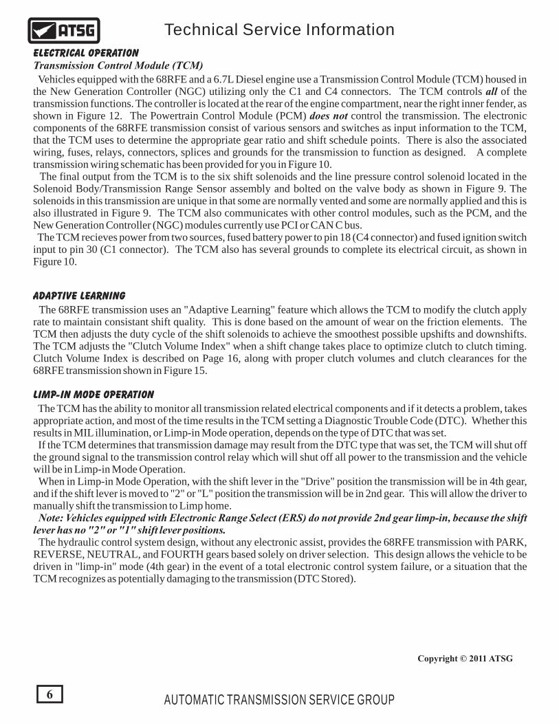
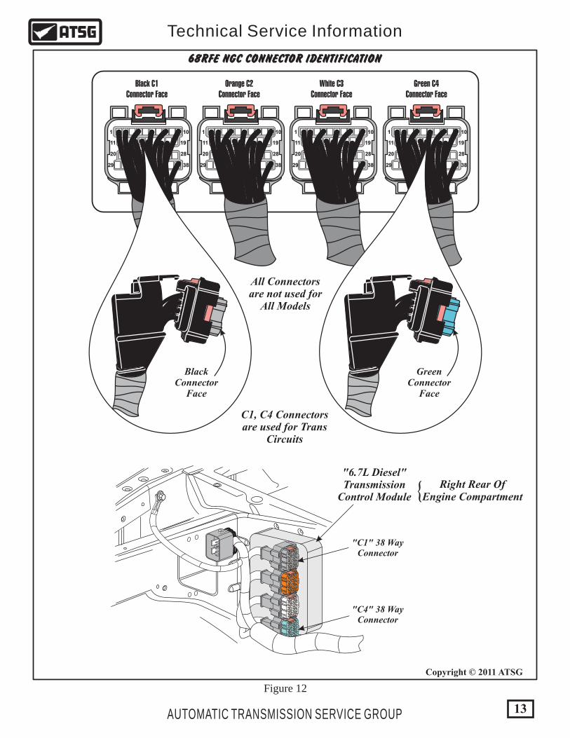
Vehicles equipped with the 68RFE and a 6.7L Diesel engine use a Transmission Control Module (TCM) housed in the New Generation Controller (NGC) utilizing only the C1 and C4 connectors. The TCM controls all of the transmission functions. The controller is located at the rear of the engine compartment, near the right inner fender, as shown in Figure 12. The Powertrain Control Module (PCM) does not control the transmission. The electronic components of the 68RFE transmission consist of various sensors and switches as input information to the TCM, that the TCM uses to determine the appropriate gear ratio and shift schedule points. There is also the associated wiring, fuses, relays, connectors, splices and grounds for the transmission to function as designed. A complete transmission wiring schematic has been provided for you in Figure 10. The final output from the TCM is to the six shift solenoids and the line pressure control solenoid located in the Solenoid Body/Transmission Range Sensor assembly and bolted on the valve body as shown in Figure 9. The solenoids in this transmission are unique in that some are normally vented and some are normally applied and this is also illustrated in Figure 9. The TCM also communicates with other control modules, such as the PCM, and the New Generation Controller (NGC) modules currently use PCI or CAN C bus. The TCM recieves power from two sources, fused battery power to pin 18 (C4 connector) and fused ignition switch input to pin 30 (C1 connector). The TCM also has several grounds to complete its electrical circuit, as shown in Figure 10.
6
Copyright © 2011 ATSG
AUTOMATIC TRANSMISSION SERVICE GROUP
Technical Service Information
LIMP-IN MODE OPERATION
The TCM has the ability to monitor all transmission related electrical components and if it detects a problem, takes appropriate action, and most of the time results in the TCM setting a Diagnostic Trouble Code (DTC). Whether this results in MIL illumination, or Limp-in Mode operation, depends on the type of DTC that was set. If the TCM determines that transmission damage may result from the DTC type that was set, the TCM will shut off the ground signal to the transmission control relay which will shut off all power to the transmission and the vehicle will be in Limp-in Mode Operation. When in Limp-in Mode Operation, with the shift lever in the "Drive" position the transmission will be in 4th gear, and if the shift lever is moved to "2" or "L" position the transmission will be in 2nd gear. This will allow the driver to manually shift the transmission to Limp home. Note: Vehicles equipped with Electronic Range Select (ERS) do not provide 2nd gear limp-in, because the shift lever has no "2" or "1" shift lever positions. The hydraulic control system design, without any electronic assist, provides the 68RFE transmission with PARK, REVERSE, NEUTRAL, and FOURTH gears based solely on driver selection. This design allows the vehicle to be driven in "limp-in" mode (4th gear) in the event of a total electronic control system failure, or a situation that the TCM recognizes as potentially damaging to the transmission (DTC Stored).
ADAPTIVE LEARNING
The 68RFE transmission uses an "Adaptive Learning" feature which allows the TCM to modify the clutch apply rate to maintain consistant shift quality. This is done based on the amount of wear on the friction elements. The TCM then adjusts the duty cycle of the shift solenoids to achieve the smoothest possible upshifts and downshifts. The TCM adjusts the "Clutch Volume Index" when a shift change takes place to optimize clutch to clutch timing. Clutch Volume Index is described on Page 16, along with proper clutch volumes and clutch clearances for the 68RFE transmission shown in Figure 15.
Transmission Control Module (TCM)

OutputSpeedSensor
InputSpeedSensor
C433
C434
C432
TCM
7
Copyright © 2011 ATSG
AUTOMATIC TRANSMISSION SERVICE GROUP
Technical Service Information
INPUTS TO THE TCM
Input and Output Shaft Speed Sensors - are located on the left side of the transmission and are illustrated in Figure 5. The input shaft speed sensor reads input shaft speed off of a tone wheel on the input clutch housing. As the teeth of the tone wheel pass the sensor coil, an AC voltage is generated and sent to the TCM. The TCM interprets this information as input shaft rpm. The output speed sensor generates an AC signal in a similar fashion, though its coil is excited by rotation of the parking gear teeth. The TCM interprets this information as output shaft rpm. The TCM compares the input and output speed signals to determine the following: Transmission gear ratio. Speed ratio error detection. Clutch Volume Index calulation. Torque Converter Clutch slippage. Both speed sensors are the same and will interchange. New speed sensors, when checked for resistance, read 535 ohms at room temperature.
Pressure Switches - are located inside the solenoid and pressure switch assembly and are only serviced by replacing the complete solenoid/TRS assembly. The TCM relies on five pressure switches to monitor pressure in the Low/Rev, 2nd Clutch, 4th Clutch, Underdrive, and Overdrive hydraulic circuits. The primary function of these switches is to help the TCM detect when clutch circuit hydraulic failures occur. The switches close at 23 psi and open at 11 psi, and indicate whether or not pressure exists. The switches are continuously monitored by the TCM for the proper states (Open or Closed) in each gear, shown in the chart in Figure 4.
1777 2
B
05 8 52 1
4 P1 97 40 A
T T 1 74
:14
J70
1
I7
8 0 4
2 54
T
:
05
B R E
14
F
P 297
A
1
047
INPUT SPEEDSENSOR
OUTPUT SPEEDSENSOR
68RFE PRESSURE SWITCH CHART2nd Clut 4th Clut Underdrive Overdrive
Reverse
First
Second
Third
Fourth
Fifth
Sixth
Park/Neut
Low/Rev
Closed
Closed
Closed
Closed
Closed
Closed Closed
Closed
Closed
Closed
Closed Closed Closed
Closed*
Open Open
Open
Open
Open
Open
Open
Open
Open
Open
Open
Open
Open
Open Open
Open
Open
Open
Open
Open
Open
Open
Open
Open
Open
Open
* L/R is closed if output speed is below 150 RPM in Drive and Manual 2. L/R is open in Manual 1.
Figure 4
Figure 5
Copyright © 2011 ATSG
Inputs To The TCMContinued on Page 8
Dk
Gre
en/O
ran
ge
Dk
Gre
en/V
iole
t
Dk
Gre
en/B
row
n
Dk Green/Violet TwistedPair
TwistedPair
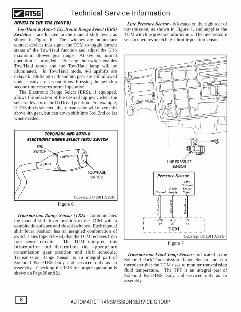
Figure 6
Figure 7
Copyright © 2011 ATSG
Copyright © 2011 ATSG
TOW/HAUL AND AUTO-6ELECTRONIC RANGE SELECT (ERS) SWITCH
Tow/Haul & Auto-6 Electronic Range Select (ERS) Switches - are located in the manual shift lever, as shown in Figure 6. The switches are momentary contact devices that signal the TCM to toggle current status of the Tow/Haul function and adjust the ERS maximum allowed gear range. At key on, normal operation is provided. Pressing the switch enables Tow/Haul mode and the Tow/Haul lamp will be illuminated. In Tow/Haul mode, 4-5 upshifts are delayed. Shifts into 5th and 6th gear are still allowed under steady cruise conditions. Pressing the switch a second time restores normal operation. The Electronic Range Select (ERS), if equipped, allows the selection of the desired top gear, when the selector lever is in the D (Drive) position. For example, if ERS 4th is selected, the transmission will never shift above 4th gear, but can down shift into 3rd, 2nd or 1st when needed.
INPUTS TO THE TCM (Cont'd)
T HOW AUL
AUTO-6
+
ERSSWITCH
TOW/HAULSWITCH
Line Pressure Sensor - is located on the right rear of transmission, as shown in Figure 7, and supplies the TCM with line pressure information. The line pressure sensor operates much like a throttle position sensor.
Transmission Fluid Temp Sensor - is located in the Solenoid Pack/Transmission Range Sensor and is a thermister that the TCM uses to moniter transmission fluid temperature. The TFT is an integral part of Solenoid Pack/TRS body and serviced only as an assembly.
Transmission Range Sensor (TRS) - communicates the manual shift lever position to the TCM with a combination of open and closed switches. Each manual shift lever position has an assigned combination of switch states (open/closed) that the TCM recieves from four sense circuits. The TCM interprets this information and determines the appropriate transmission gear position and shift schedule. Transmission Range Sensor is an integral part of Solenoid Pack/TRS body and serviced only as an assembly. Checking the TRS for proper operation is shown on Page 20 and 21.
LINE PRESSURESENSOR
Yell
ow/B
row
n
Yell
ow/P
ink
Dk
Gre
en/W
hit
e
LinePressureSensorSignal
5 VoltSupplyGround
Pressure Sensor
(C1)19
(C1)27
C431
TCM
8 AUTOMATIC TRANSMISSION SERVICE GROUP
Technical Service Information

9AUTOMATIC TRANSMISSION SERVICE GROUP
Technical Service Information
OUTPUTS FROM THE TCM
Transmission Control Relay - is located in the Integrated Power Distribution Module (IPDM), as shown in Figure 8, and recieves a ground signal from terminal (C1) 18 at the TCM to close the relay. Refer to the wiring schematic in Figure 10.
Underdrive Solenoid - is normally applied and controls oil to the Underdrive Clutch in 1st, 2nd, 3rd, and 4th gears of the transmission.
Overdrive Solenoid - is normally vented and controls oil to the Overdrive Clutch in 4th, 5th, and 6th gears in the transmission.
4th Clutch Solenoid - is normally vented and controls oil to the 4th clutch in 3rd and 5th gears in the transmission.
2nd Clutch Solenoid - is normally vented and controls oil to the 2nd clutch in 2nd and 6th gears in the transmission.
Low/Reverse Solenoid - is normally vented and is used to apply the Low/Reverse clutch in 1st gear from Park or Neutral, or a coast down to 1st gear. This solenoid also controls oil pressure for the converter clutch engagement based on switch valve position.
Line Pressure Solenoid - is normally vented and is used to controll all oil pressures in the transmission. Note: Refer to Page 20 for a solenoid resistance chart for all solenoids.
Multi-Select Solenoid - is normally applied and controls the Overdrive Clutch in 4th gear Limp-in, and the Low/Reverse clutch for reverse block. This solenoid is Off below 8 MPH, On above 8 MPH.
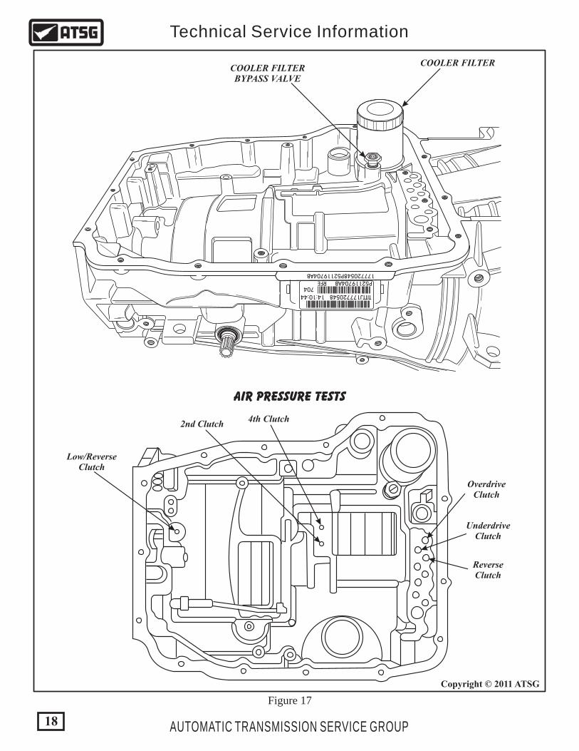
DIAGNOSIS AND SERVICE INFORMATION
You have been provided with the 23-way case connector pin cavity identification and pin function in Figure 11. The 38-way Diesel NGC/TCM connector pin cavity identification and pin function is shown in Figure 13 and 14. A complete transmission wiring schematic is provided in Figure 10, and transmission control relay location in the power distribution center is shown in Figure 9. Special tools that might be needed are illustrated on Page 26 and 27, along with the identification of the pressure taps that are available on the main valve body. Air pressure test passage identification is provided for you in Figure 17.
SpareRelay
SpareRelay
HornRelay
ACClutchRelay
WiperOn/OffRelay
WiperHi/LoRelay
HeaterRelayDown-Stream
HeaterRelayUp-
Stream
StarterRelay
FuelPumpRelay
AutomaticShutdown
Relay
TransmissionControlRelay
Fuse(30A)
TRANSMISSION CONTROL RELAY LOCATION
Integrated PowerDistribution Module
(IPDM)
Located In Engine CompartmentOn Left Fender Well
Model SensitiveAll Models Have Schematic
In the IPDM Cover To IdentifyLocations
Copyright © 2011 ATSG
Figure 8

4799591
97
Figure 9
"Solenoid Off""Normally Applied"
"Solenoid Off""Normally Vented"
Underdrive SolenoidMulti-Select Solenoid
Overdrive Solenoid4th Clutch Solenoid2nd Clutch Solenoid
Low/Reverse SolenoidLine Pressure Solenoid
TWO DIFFERENT TYPES OF SHIFT SOLENOIDS
VALVE BODY
PRESSURECONTROLSOLENOID
SOLENOIDPACK
23-WAYCONNECTOR
TRANSMISSIONRANGE SENSOR
4th ClutchSeal
2nd ClutchSeal
L/R ClutchSeal
10
Copyright © 2011 ATSG
AUTOMATIC TRANSMISSION SERVICE GROUP
Technical Service Information

11AUTOMATIC TRANSMISSION SERVICE GROUP
Technical Service Information
Figure 10
Copyright © 2011 ATSG
L/RPressureSwitch
2nd ClutPressureSwitch
ODPressureSwitch
4th ClutPressureSwitch
UDPressureSwitch
TRS(C2)T42
Signal
TRS(C1)T41
Signal
TRS(C3)T3
Signal
TRS(C5)T2
Signal
TRS(C4)T1
Signal
LinePressureSensorSignal
5 VoltSupplyGround
Pressure Sensor
Mu
lti-
Sel
ect
Sol
enoi
d
Un
derd
rive
Sol
enoi
d
Ove
rdri
veS
olen
oid
2nd
Clu
tch
Sol
enoi
d
4th
Clu
tch
Sol
enoi
d
LR
/TC
CS
olen
oid
Pre
ssu
reC
ontr
olS
olen
oid
OutputSpeedSensor
InputSpeedSensor
IgnitionSwitch
12V
INTEGRATED POWER DISTRIBUTION MODULE
TRANSMISSIONCONTROL RELAYFUSE
30A
10 1217 721 23 2220 19 18 16 15 14 138 9 4 3 5 1 6112
TRANSMISSION CONTROL MODULE/NEW GENERATION CONTROLLER
C418
C419
C428
C438
(C1)19
(C1)27
C431
C414
C413
C412
C435
(T42)C437
(T41)C427
(T1)C415
(T2)C426
(T3)C416
C429
C430
C422
C420
C421
C411
C410
C42
C46
C48
C44
C41
C433
C434
C432
(C1)30
TFTSensor
(C1)18
(C1)9
Term 1, 3, 6Not Used
6.7L DIESEL WIRE SCHEMATIC See Figure 11, 12, 13, 14For Connector ID
See Page 28 ForAPPS Information
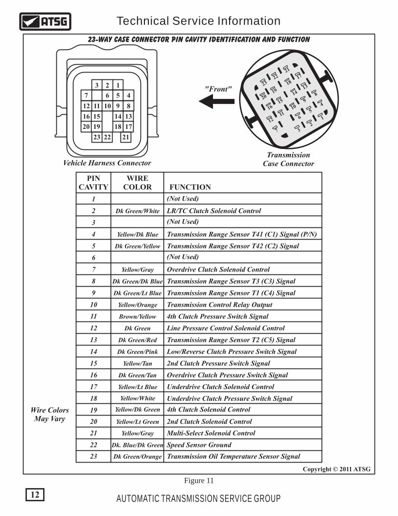
Figure 11
12
Copyright © 2011 ATSG
AUTOMATIC TRANSMISSION SERVICE GROUP
Technical Service Information
123
4
89101112
13
17181920
212223
141516
567
PINCAVITY
WIRECOLOR FUNCTION
Yellow/Dk Blue
Dk Green/Yellow
Dk Green/Red
Dk Green/Tan
Dk Green/Dk Blue
Yellow/Gray
Dk Green/Orange
Yellow/Orange
Yellow/Lt Blue
Yellow/White
Yellow/Dk Green
Brown/Yellow
Dk. Blue/Dk Green
Dk Green
Yellow/Lt Green
Yellow/Gray
Dk Green/Pink
Yellow/Tan
Dk Green/White
Dk Green/Lt Blue
LR/TC Clutch Solenoid Control
(Not Used)
(Not Used)
(Not Used)
Overdrive Clutch Solenoid Control
Line Pressure Control Solenoid Control
Underdrive Clutch Solenoid Control
4th Clutch Solenoid Control
2nd Clutch Solenoid Control
Multi-Select Solenoid Control
Speed Sensor Ground
Transmission Oil Temperature Sensor Signal
Transmission Control Relay Output
4th Clutch Pressure Switch Signal
2nd Clutch Pressure Switch Signal
Low/Reverse Clutch Pressure Switch Signal
Overdrive Clutch Pressure Switch Signal
Underdrive Clutch Pressure Switch Signal
Transmission Range Sensor T41 (C1) Signal (P/N)
Transmission Range Sensor T42 (C2) Signal
Transmission Range Sensor T3 (C3) Signal
Transmission Range Sensor T1 (C4) Signal
Transmission Range Sensor T2 (C5) Signal
1
2
3
4
5
6
7
8
9
10
11
12
13
14
15
16
17
18
19
20
21
22
23
23-WAY CASE CONNECTOR PIN CAVITY IDENTIFICATION AND FUNCTION
1
4
8
5
9
6
01
11
12
13
17
14
81
15
19
16
20
21
22
23
72
3
Vehicle Harness ConnectorTransmission
Case Connector
"Front"
Wire ColorsMay Vary
13
Copyright © 2011 ATSG
AUTOMATIC TRANSMISSION SERVICE GROUP
Technical Service Information
68RFE NGC CONNECTOR IDENTIFICATION
Orange C2Connector Face
Black C1Connector Face
Green C4 Connector Face
White C3Connector Face
All Connectorsare not used for
All Models
C1, C4 Connectorsare used for Trans
Circuits
"6.7L Diesel"Transmission
Control Module
1 10
11 19
20 28
29 38
1 10
11 19
20 28
29 38
1 10
11 19
20 28
29 38
1 10
11 19
20 28
29 38
BlackConnector
Face
GreenConnector
Face
"C1" 38 WayConnector
Right Rear OfEngine Compartment
"C4" 38 WayConnector
Figure 12
{
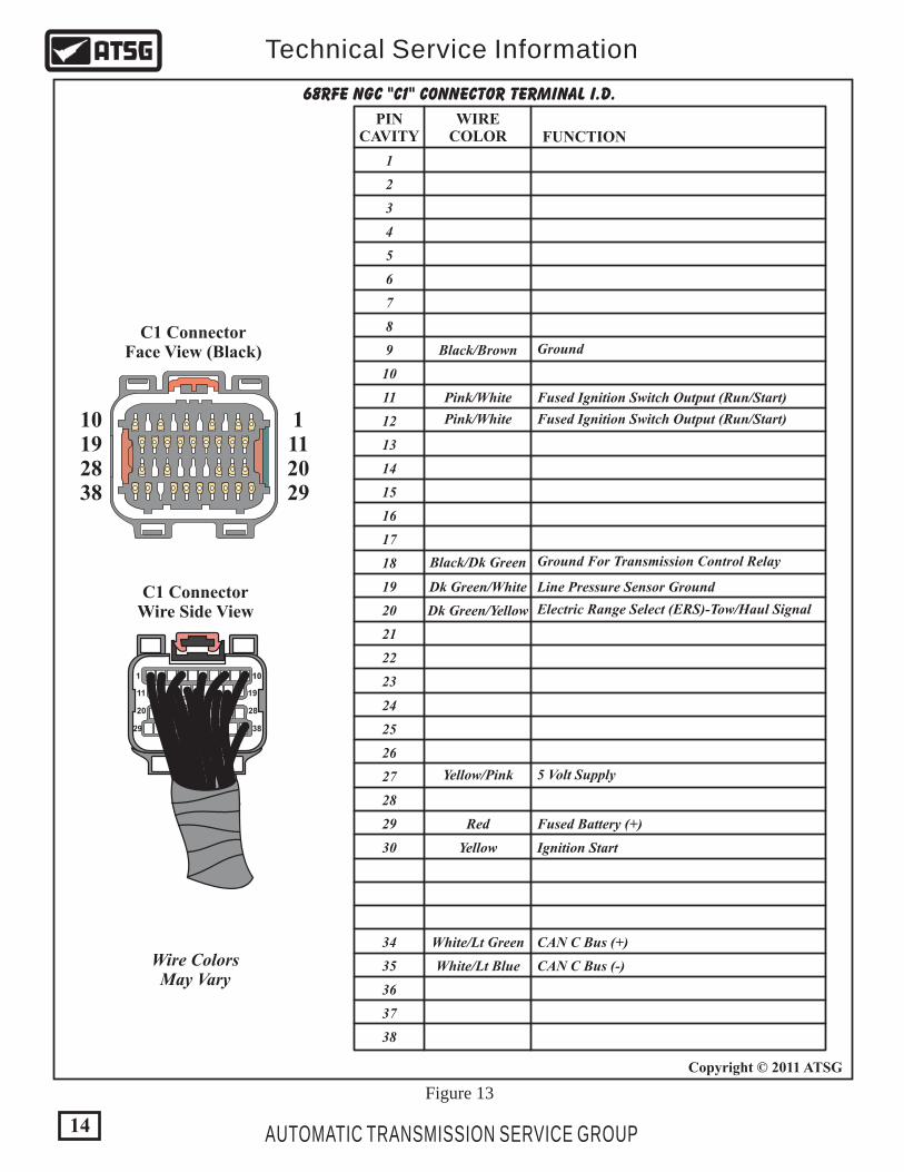
C1 ConnectorWire Side View
C1 ConnectorFace View (Black)
1112029
10192838
PINCAVITY
WIRECOLOR FUNCTION
Dk Green/White
Pink/White
Black/Brown
Black/Dk Green
Pink/White
Dk Green/Yellow
Line Pressure Sensor Ground
Electric Range Select (ERS)-Tow/Haul Signal
Fused Ignition Switch Output (Run/Start)
Ground
Ground For Transmission Control Relay
Fused Ignition Switch Output (Run/Start)
1
2
3
4
5
6
7
8
9
10
11
12
13
14
15
16
17
18
19
20
21
22
23
Yellow/Pink
White/Lt Green
White/Lt Blue
Red
Yellow
CAN C Bus (+)
CAN C Bus (-)
5 Volt Supply
Ignition Start
Fused Battery (+)
24
25
26
27
28
29
30
34
35
36
37
38
68RFE NGC "C1" CONNECTOR TERMINAL I.D.
Figure 13
1 10
11 19
20 28
29 38
Wire ColorsMay Vary
14
Copyright © 2011 ATSG
AUTOMATIC TRANSMISSION SERVICE GROUP
Technical Service Information

C4 ConnectorWire Side View
Wire ColorsMay Vary
C4 ConnectorFace View (Green)
1112029
10192838
PINCAVITY
WIRECOLOR FUNCTION
Yellow/Gray
Dk Green
Yellow/Lt Green
Black
Dk Green/Dk Blue
Yellow/Lt Blue
Yellow/White
Dk Green/White
Dk Green
Yellow/Dk Blue
Yellow/Orange
Yellow/Gray
Dk Green/Tan
Black
Brown/Yellow
Black
Dk Green/Lt Blue
Yellow/Dk Green
Overdrive Clutch Solenoid Control
4th Clutch Solenoid Control
Ground
Towhaul Overdrive Off Switch Sense
Transmission Control Relay Output
4th Clutch Pressure Switch Signal
Underdrive Clutch Pressure Switch Signal
Overdrive Clutch Pressure Switch Signal
LR/TC Clutch Solenoid Control
Line Pressure Control Solenoid Control
Transmission Range Sensor T1 (C4) Signal
Ground
Transmission Range Sensor T3 (C3) Signal
Transmission Control Relay Control
Multi-Select Solenoid Control
2nd Clutch Solenoid Control
Underdrive Clutch Solenoid Control
Ground
1
2
3
4
5
6
7
8
9
10
11
12
13
14
15
16
17
18
19
20
21
22
23
Yellow/Orange
Yellow/Dk Blue
Yellow/Brown
Yellow/Orange
Dk Green/Brown
Dk Green/Orange
Dk Green/Violet
Dk Green/Lt Blue
Dk Green/Yellow
Dk Green/Orange
Yellow/Tan
Dk Green/Yellow
Output Speed Sensor Signal
Speed Sensor Ground
Transmission Oil Temperature Sensor Signal
Transmission Range Sensor T42 (C2) Signal
Transmission Control Relay Output
Transmission Range Sensor T2 (C5) Signal
Transmission Range Sensor T41 (C1) Signal
2nd Clutch Pressure Switch Signal
Low/Reverse Clutch Pressure Switch Signal
Line Pressure Sensor Signal
Input Speed Sensor Signal
Transmission Control Relay Output
24
25
26
27
28
29
30
31
32
33
34
35
36
37
38
68RFE NGC "C4" CONNECTOR TERMINAL I.D.
Figure 14
1 10
11 19
20 28
29 38
15
Copyright © 2011 ATSG
AUTOMATIC TRANSMISSION SERVICE GROUP
Technical Service Information

CLUTCH VOLUMES AND CLEARANCES
CLUTCH WHEN UPDATED PROPER VOLUME CLUTCH CLEARANCE
Low/Reverse
Reverse
2-1, 3-1 or 4-1 Downshift 45 to 134 1.18-2.09mm (.046"-.082")
0.99-1.65mm (.039"-.065")
0.99-1.65mm (.039"-.065")
0.77-1.39mm (.030"-.055")
0.77-1.39mm (.030"-.055")
0.58-1.47mm (.023"-.058")
0.75-1.61mm (.030"-.063")
1.02-1.72mm (.040"-.068")
25 to 85
25 to 85
30 to 100
30 to 85
30 to 85
30 to 100
4-3 or3-2 Downshift
5-6 Upshift
5-4 or 6-4 Kickdown shift
Not Monitored Not Monitored
3-4 Upshift
4-5 Upshift
4-5 Upshift
2nd Clutch
2nd Clutch
Overdrive
4th Clutch
4th Clutch
Underdrive
CLUTCH VOLUME INDEXES
OIL PUMP OPERATION
An important function of the TCM is to monitor Clutch Volume Indexes (CVI). CVIs represent the volume of fluid needed to compress a clutch pack properly.The TCM monitors gear ratio changes by monitoring the Input and Output Speed Sensors. The Input Speed Sensor sends an AC voltage signal to the TCM that represents input shaft rpm. The Output Speed Sensor provides the TCM with output shaft speed information.By comparing these two inputs, the TCM can determine actual gear ratio. This is important to the CVI calculation because the TCM determines CVIs by monitoring how long it takes for a gear change to occur.Gear ratios can be determined by using the DRB Scan Tool and reading the Input/Output Speed Sensor values in the "Monitors" display. Gear ratio can be obtained by dividing the Input Speed Sensor value by the Output Speed Sensor value.For example, if the input shaft is turning at 1000 rpm and the output shaft is turning at 500 rpm, the TCM can determine that the gear ratio is 2:1. In 3rd gear the gear ratio changes to 1:1. The gear ratio changes as clutches are applied and released. By monitoring the length of time it takes for a gear ratio to change following a shift request, the TCM can determine the volume of fluid used to apply or release a friction element.The volume of transmission fluid needed to apply the friction elements are continuously updated for the adaptive controls. As friction material wears, the volume of fluid needed to apply the friction element increases.Certain mechanical problems within the transmission assembly such as broken return springs, out of position snap rings, excessive clutch pack clearance, or improper assembly can cause inadequate or out-of-range CVI readings. The chart in Figure 15 identifies the proper CVIs, when they are monitored and updated, and the proper clutch pack clearances.
Figure 15
16
Copyright © 2011 ATSG
AUTOMATIC TRANSMISSION SERVICE GROUP
Technical Service Information
A dual stage oil pump is also used for the 68RFE. The pump has three gears, one drive gear and two driven gears as shown in Figure 16. Both stages of the pump supply fluid during idle and at low engine speeds. Under these conditions there is not enough pressure from the primary stage to close the shuttle valve. As engine speed increases, so does the output from the primary stage. Once the pressure from the primary stage builds up, the shuttle valve is forced closed and in this condition the secondary stage has no effect and the primary side supplies all of the pressure needed for proper transmission operation. The 68RFE pump has four lugs on the drive gear instead of the previous two and the driven gears now rotate on a permanent shaft that is part of the oil pump body, as shown in Figure 16. The oil pump body also no longer contains a pocket for the converter hub seal, as the seal is in front cover. These features make the oil pumps non-interchangeable.

Figure 16
17
Copyright © 2011 ATSG
AUTOMATIC TRANSMISSION SERVICE GROUP
Technical Service Information
68RFE OIL PUMP BODY AND GEARS
Shuttle Valve
Four Drive Lugs OnDrive Gear And FourFlats On Converter
Driven Gears NowRotate On PermanentShafts In Punp Body
Driven Gears NowRotate On PermanentShafts In Punp Body
177720548P52119704AB
TITTJ177720548 14:10:44
P52119704AB RFE704
Low/ReverseClutch
2nd Clutch4th Clutch
OverdriveClutch
UnderdriveClutch
ReverseClutch
Figure 17
COOLER FILTERCOOLER FILTERBYPASS VALVE
AIR PRESSURE TESTS
18
Copyright © 2011 ATSG
AUTOMATIC TRANSMISSION SERVICE GROUP
Technical Service Information

177720548P52119704AB
TITTJ177720548 14:10:44
P52119704AB RFE
704
LINE PRESSURESENSOR "FROM" COOLER
LOCK-UP "ON"PRESSURE
LOCK-UP "OFF"PRESSURE
INPUT SPEEDSENSOR
OUTPUT SPEEDSENSOR
"TO" COOLER
Figure 18
19
Copyright © 2011 ATSG
AUTOMATIC TRANSMISSION SERVICE GROUP
Technical Service Information
EXTERNAL SENSOR LOCATIONS AND COOLER LINE IDENTIFICATION

Figure 19
T2 (C5)T1 (C4)T3 (C3)
T42 (C2)T41 (C1)
TRANSMISSION RANGE SENSOR/SOLENOID BODY TESTS
20
Copyright © 2011 ATSG
AUTOMATIC TRANSMISSION SERVICE GROUP
Technical Service Information
TRANSMISSION RANGE SENSOR CHART
CIRCUIT METER P R N OD 2* 1*
C
C
C
C = Closed O = Open
C C
C C
C
C
C
C
C
CO O
O
O O
O O O
O O
O O
O
O
O
O OT41 (C1)
T42 (C2)
T3 (C3)
T1 (C4)
T2 (C5)
T41 & GRD OR CONNECTOR PIN 4 & GRD
T42 & GRD OR CONNECTOR PIN 5 & GRD
T3 & GRD OR CONNECTOR PIN 8 & GRD
T1 & GRD OR CONNECTOR PIN 9 & GRD
T2 & GRD OR CONNECTOR PIN 13 & GRD
* Vehicles equipped with Electronic Range Selector (ERS) do not have "2" or "1" positions on the shift lever.
SOLENOID RESISTANCE CHART
RESISTANCESOLENOID
LR/TCC 10 AND 2
10 AND 7
10 AND 17
10 AND 20
10 AND 19
10 AND 21
10 AND 12
22 AND 23
OVERDRIVE
UNDERDRIVE
2ND CLUTCH
4TH CLUTCH
MULTI-SELECT
LINE PRESSURE
TOT SENSOR
23-WAY CONN. PINS
1.9 W @ 72°F
1.9 W @ 72°F
1.9 W @ 72°F
1.9 W @ 72°F
1.9 W @ 72°F
1.9 W @ 72°F
4.3 W @ 72°F
9.37k W @ 72°F
See Figure 20 For 23/Way Connector Pin Identification.

Meter shown at T41 (C1) Circuit and should correspond with chart in Figure 19. Solenoid tests "must" be made thru case connector pins.
4799591
97
Figure 20
23-WAYCONNECTOR
TRANSMISSION RANGE SENSORAND SOLENOID BODY ASSEMBLY
1
4
8
5
9
6
10
1112
13
17
14
81
15
19
16
20
21
22
23
72
3
TransmissionCase Connector
"Front"
W0.1
OFF
RPM
RPMCOMmAA
V
V
mVW
W
VmAA
mAA
21
Copyright © 2011 ATSG
AUTOMATIC TRANSMISSION SERVICE GROUP
Technical Service Information

DTC
68RFE DIAGNOSTIC TROUBLE CODES
DESCRIPTION
P0122
P0101
P0102
P0103
P0116
P0117
P0118
P0123
P0124
P0218
P0562
P0563
P0571
P0572
P0573
P0560
P0604
P0605
TPS/APP Circuit Low
Mass Air Flow Sensor Circuit Performance
Engine Coolant Sensor Circuit Performance
Engine Coolant Sensor Circuit Low
Engine Coolant Sensor Circuit High
Mass Air Flow Sensor Circuit Low
Mass Air Flow Sensor Circuit High
TPS/APP Circuit High
TPS/APP Circuit Intermittent
High Temperature Operation Activated
Battery System Voltage
Battery System Voltage Low
Battery System Voltage High
Brake Switch Performance
Brake Switch Stuck On
Brake Switch Stuck Off
Control Module, Internal RAM Error
Control Module, Internal ROM Error
P0613
P0706
P0707
P0708
P0700
P0702
P0711
P0712
P0713
P0714
P0715
P0717
P0721
P0722
Internal Transmission Control Module Error
Transmission Control System, MIL Request
Transmission Control System, Electrical
Transmission Range Sensor Rationallity
Transmission Range Sensor Circuit Low
Transmission Range Sensor Circuit High
Transmission Temperature Sensor Performance
Transmission Temperature Sensor Circuit Low
Transmission Temperature Sensor Circuit High
Transmission Temperature Sensor Circuit Intermittent
Input Speed Sensor Circuit Performance
Input Speed Sensor, No Signal
Output Speed Sensor, No Signal
Output Speed Sensor Performance
Continued on Page 23
Figure 21
22
Copyright © 2011 ATSG
AUTOMATIC TRANSMISSION SERVICE GROUP
Technical Service Information

DTC
68RFE DIAGNOSTIC TROUBLE CODES
DESCRIPTION
P0871
P0875
P0876
P0884
P0883
P0882
P0890
P0933
P0934
P0935
P0944
P0957
Overdrive Clutch Pressure Switch Rationallity
Underdrive Clutch Pressure Switch Rationallity
Power Up At Speed
Transmission Control Module Power Input Low
Transmission Control Module Power Input High
Line Pressure Sensor Performance
Line Pressure Sensor Circuit Low
Line Pressure Sensor Circuit High
Loss If Hydraulic Prime
Autostick Circuit Low (Electronic Range Select)
Switched Battery Fault
Underdrive Clutch Pressure, Pressure Test
P0750
P0755
P0760
P0765
P0770
P0841
P0845
P0846
P0854
P0868
P0869
P0870
Low/Reverse Clutch Solenoid Circuit Fault
Low/Reverse Clutch Pressure Switch Rationallity
Second Clutch Pressure Switch Rationallity
Line Pressure Low
Line Pressure High
Second Clutch Pressure Switch, Pressure Test
Overdrive Clutch Pressure, Pressure Test
Second Clutch Solenoid Circuit Fault
Overdrive Clutch Solenoid Circuit Fault
Overdrive Clutch Switch Circuit Low
Underdrive Clutch Solenoid Circuit Fault
Fourth Clutch Solenoid Circuit Fault
P0729
P0731
P0732
P0733
P0734
P0735
P0736
P0740
P0745
First Gear Ratio Error
Second Gear Ratio Error
Third Gear Ratio Error
Fourth Gear Ratio Error
Fifth Gear Ratio Error
Reverse Gear Ratio Error
Sixth Gear Ratio Error
Torque Converter Clutch Out Of Range (Slip Fault)
Line Pressure Solenoid Circuit
Continued on Page 24
Figure 22
23
Copyright © 2011 ATSG
AUTOMATIC TRANSMISSION SERVICE GROUP
Technical Service Information

DTC
68RFE DIAGNOSTIC TROUBLE CODES
DESCRIPTION
P0987
P0988
P1679
P1684
P1715
P1720
P1775
P1776
P1794
P2700
P2701
P2702
P2703
P2704
P2706
P2741
P2742
P2743
P2757
P2806
Fourth Clutch Pressure, Pressure Test
Fourth Clutch Pressure Switch Rationallity
Calibration Not Learned
Battery Was Disconnected
Restricted Manual Valve In T3 Range
Input Speed Sensor, No Signal
Speed Sensor, Ground Error
Inadequate Element Volume In Low/Reverse Clutch
Inadequate Element Volume In Second Clutch
Inadequate Element Volume In Overdrive Clutch
Inadequate Element Volume In Underdrive Clutch
Inadequate Element Volume In Fourth Clutch
Multi-Select Solenoid Circuit Fault
Transmission Fluid Temperature Sensor Performance
Transmission Fluid Temperature Sensor Low
Transmission Fluid Temperature Sensor High
Transmission Range Sensor Alignment
TCC Pressure Control Solenoid, Control Circuit Performance
Solenoid Switch Valve, Latched In TCC position
Solenoid Switch Valve, Latched In LowReverse position
Figure 23
24
Copyright © 2011 ATSG
AUTOMATIC TRANSMISSION SERVICE GROUP
Technical Service Information
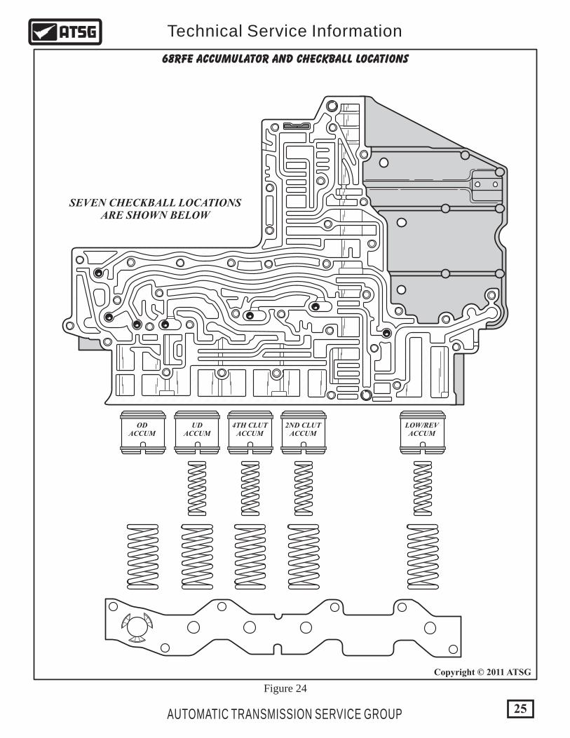
ODACCUM
UDACCUM
4TH CLUTACCUM
2ND CLUTACCUM
LOW/REVACCUM
SEVEN CHECKBALL LOCATIONSARE SHOWN BELOW
68RFE ACCUMULATOR AND CHECKBALL LOCATIONS
Figure 24
25
Copyright © 2011 ATSG
AUTOMATIC TRANSMISSION SERVICE GROUP
Technical Service Information
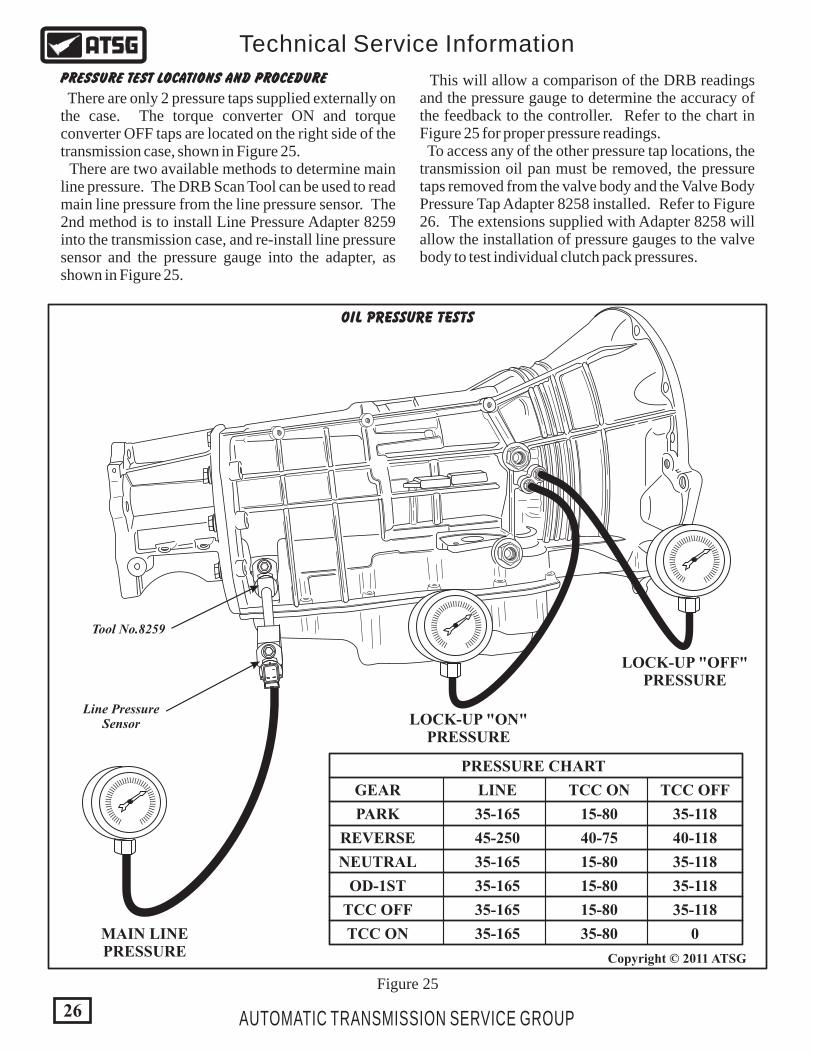
Figure 25
MAIN LINEPRESSURE
Line PressureSensor
Tool No.8259
LOCK-UP "ON"PRESSURE
LOCK-UP "OFF"PRESSURE
lllll ll ll ll ll ll ll ll ll ll ll ll ll ll ll ll ll ll llll llll ll
lllll ll ll ll ll ll ll ll ll ll ll ll ll ll ll ll ll ll llll llll ll
lllll ll ll ll ll ll ll ll ll ll ll ll ll ll ll ll ll ll llll llll ll
PRESSURE CHART
GEAR
PARK
REVERSE
NEUTRAL
OD-1ST
TCC OFF
TCC ON
LINE
35-165 35-118
40-11840-75
35-118
35-118
35-118
0
15-80
15-80
15-80
15-80
35-80
45-250
35-165
35-165
35-165
35-165
TCC ON TCC OFF
OIL PRESSURE TESTS
26
Copyright © 2011 ATSG
AUTOMATIC TRANSMISSION SERVICE GROUP
Technical Service Information
PRESSURE TEST LOCATIONS AND PROCEDURE
There are only 2 pressure taps supplied externally on the case. The torque converter ON and torque converter OFF taps are located on the right side of the transmission case, shown in Figure 25. There are two available methods to determine main line pressure. The DRB Scan Tool can be used to read main line pressure from the line pressure sensor. The 2nd method is to install Line Pressure Adapter 8259 into the transmission case, and re-install line pressure sensor and the pressure gauge into the adapter, as shown in Figure 25.
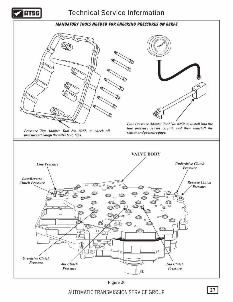
This will allow a comparison of the DRB readings and the pressure gauge to determine the accuracy of the feedback to the controller. Refer to the chart in Figure 25 for proper pressure readings. To access any of the other pressure tap locations, the transmission oil pan must be removed, the pressure taps removed from the valve body and the Valve Body Pressure Tap Adapter 8258 installed. Refer to Figure 26. The extensions supplied with Adapter 8258 will allow the installation of pressure gauges to the valve body to test individual clutch pack pressures.
27AUTOMATIC TRANSMISSION SERVICE GROUP
Technical Service Information
VALVE BODY
MANDATORY TOOLS NEEDED FOR CHECKING PRESSURES ON 68RFE
Pressure Tap Adapter Tool No. 8258, to check oil pressures through the valve body taps.
Line Pressure Adapter Tool No. 8259, to install into the line pressure sensor circuit, and then reinstall the sensor and pressure gage.
lllll ll ll ll ll ll ll ll ll ll ll ll ll ll ll ll ll ll llll llll ll
479965505111
AK 1
98
Overdrive ClutchPressure
Low/ReverseClutch Pressure
Line Pressure
4th ClutchPressure
2nd ClutchPressure
Underdrive ClutchPressure
Reverse ClutchPressure
Figure 26

FLUID LEVEL CHECK PROCEDURE
(1) Transmission fluid level must be checked before performing the pressure tests and must be at normal operating temperature for accurate check. Drive vehicle if necessary to bring fluid temperature up to normal operating temperature of 82°C (180°F). (2) Position vehicle on flat level surface. (3) Start and run engine at curb idle speed. (4) Apply Parking Brakes. (5) Shift transmission through all gear ranges and then back to the Neutral position. (6) Remove dipstick and check fluid level. (A) Correct level is in crosshatch area. (B) Correct maximum level is to MAX arrow. (C) Incorrect level is at or below MIN line. (7) If fluid level is low, add only enough of the Mopar® ATF Plus 4, to restore correct fluid level. Do not overfill (See Figure 28).
Dexron II fluid is NOT recommended. Clutch chatter can result from the use of improper fluid.
Copyright © 2011 ATSG
TYPICALDIPSTICK
MAXIMUM CORRECTFLUID LEVEL
ACCEPTABLEFLUID LEVEL
OK MAXMIN
Figure 28
Copyright © 2011 ATSG
123456
ACCELERATOR PEDAL POSITION SENSOR6.7L DIESEL DIAGNOSTIC INFORMATION
CAVITY COLOR FUNCTIONWIRE
1 Brown/Lt Blue
Brown/White
Brown/Yellow
Brown/Violet
White/Brown
Violet/Brown
APPS No. 1 Return
APPS No. 2 Return
APPS No. 1 Signal
APPS No. 2 Signal
5 Volt Supply
5 Volt Supply
2
3
4
5
6
APPSConnectorFace View
Face ViewEngine Control Module
60-Way C2 Connector (Diesel)
EngineControlModule
This Information Shared with TCM over CAN C Bus
EngineControlModule
10
20
30
40
50
60
1
11
21
31
41
51Note: numbers are marked
on connector
Accelerator Pedal Position Sensor
1
27
2
35
3
28
4
22
5
24
6
26
Bro
wn
/Lt
Blu
e
Bro
wn
/Wh
ite
ECMC2
Conn
Bro
wn
/Dk
Gre
en
Bro
wn
/Vio
let
Wh
ite/
Bro
wn
Vio
let/
Bro
wn
5 V
OLT
SUPPLY
5 V
OLT
SUPPLY
APPS
NO
. 2 S
IGN
AL
APPS
NO
. 1 S
IGN
AL
APPS
NO
. 2 R
ETURN
APPS
NO
. 1 R
ETURN
Figure 27
28 AUTOMATIC TRANSMISSION SERVICE GROUP
Technical Service Information
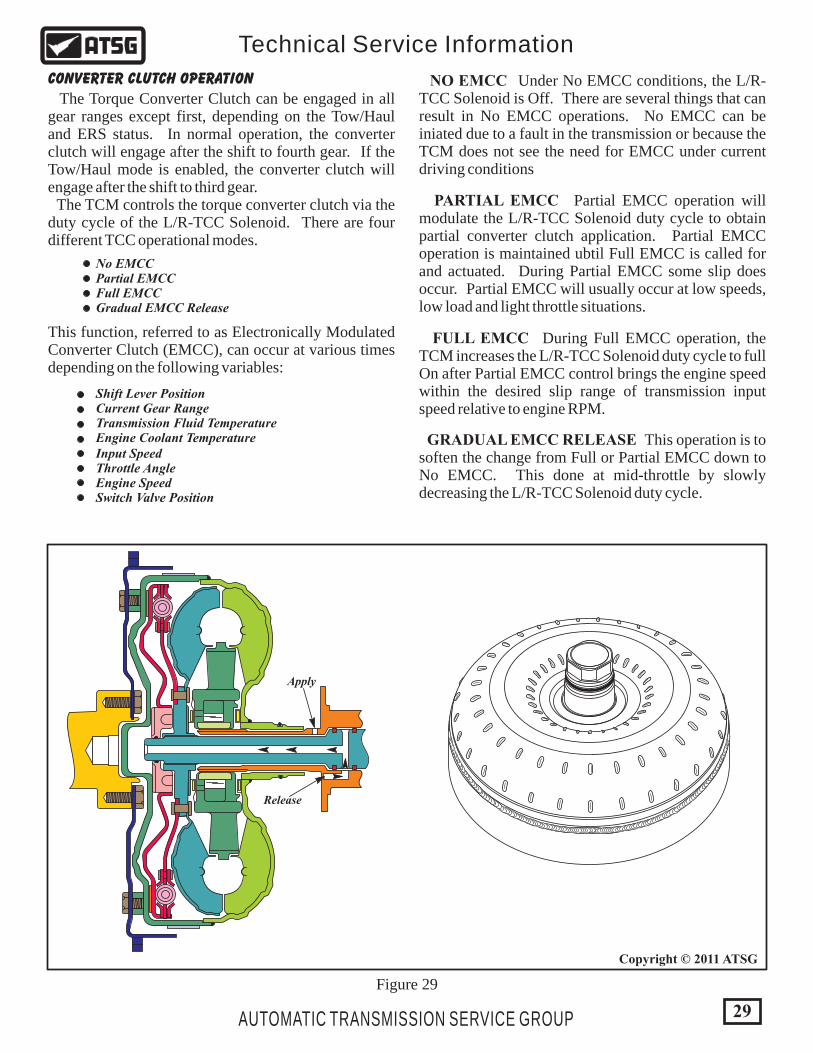
CONVERTER CLUTCH OPERATION
The Torque Converter Clutch can be engaged in all gear ranges except first, depending on the Tow/Haul and ERS status. In normal operation, the converter clutch will engage after the shift to fourth gear. If the Tow/Haul mode is enabled, the converter clutch will engage after the shift to third gear. The TCM controls the torque converter clutch via the duty cycle of the L/R-TCC Solenoid. There are four different TCC operational modes.
No EMCCPartial EMCCFull EMCCGradual EMCC Release
Shift Lever PositionCurrent Gear RangeTransmission Fluid TemperatureEngine Coolant TemperatureInput SpeedThrottle AngleEngine SpeedSwitch Valve Position
NO EMCC Under No EMCC conditions, the L/R-TCC Solenoid is Off. There are several things that can result in No EMCC operations. No EMCC can be iniated due to a fault in the transmission or because the TCM does not see the need for EMCC under current driving conditions
PARTIAL EMCC Partial EMCC operation will modulate the L/R-TCC Solenoid duty cycle to obtain partial converter clutch application. Partial EMCC operation is maintained ubtil Full EMCC is called for and actuated. During Partial EMCC some slip does occur. Partial EMCC will usually occur at low speeds, low load and light throttle situations.
FULL EMCC During Full EMCC operation, the TCM increases the L/R-TCC Solenoid duty cycle to full On after Partial EMCC control brings the engine speed within the desired slip range of transmission input speed relative to engine RPM.
GRADUAL EMCC RELEASE This operation is to soften the change from Full or Partial EMCC down to No EMCC. This done at mid-throttle by slowly decreasing the L/R-TCC Solenoid duty cycle.
Release
Apply
This function, referred to as Electronically Modulated Converter Clutch (EMCC), can occur at various times depending on the following variables:
Figure 29
29
Copyright © 2011 ATSG
AUTOMATIC TRANSMISSION SERVICE GROUP
Technical Service Information

Figure 30
68RFE CASE PASSAGE IDENTIFICATION
Low/ReverseClutch
2nd ClutchLine
Vent
Lock-Up Off
Lock-Up On
ToCooler
FromCooler
4th Clutch
OverdriveClutch
OverdriveClutch
UnderdriveClutch
UnderdriveClutch
ReverseClutch
ReverseClutch
30
Copyright © 2011 ATSG
AUTOMATIC TRANSMISSION SERVICE GROUP
Technical Service Information
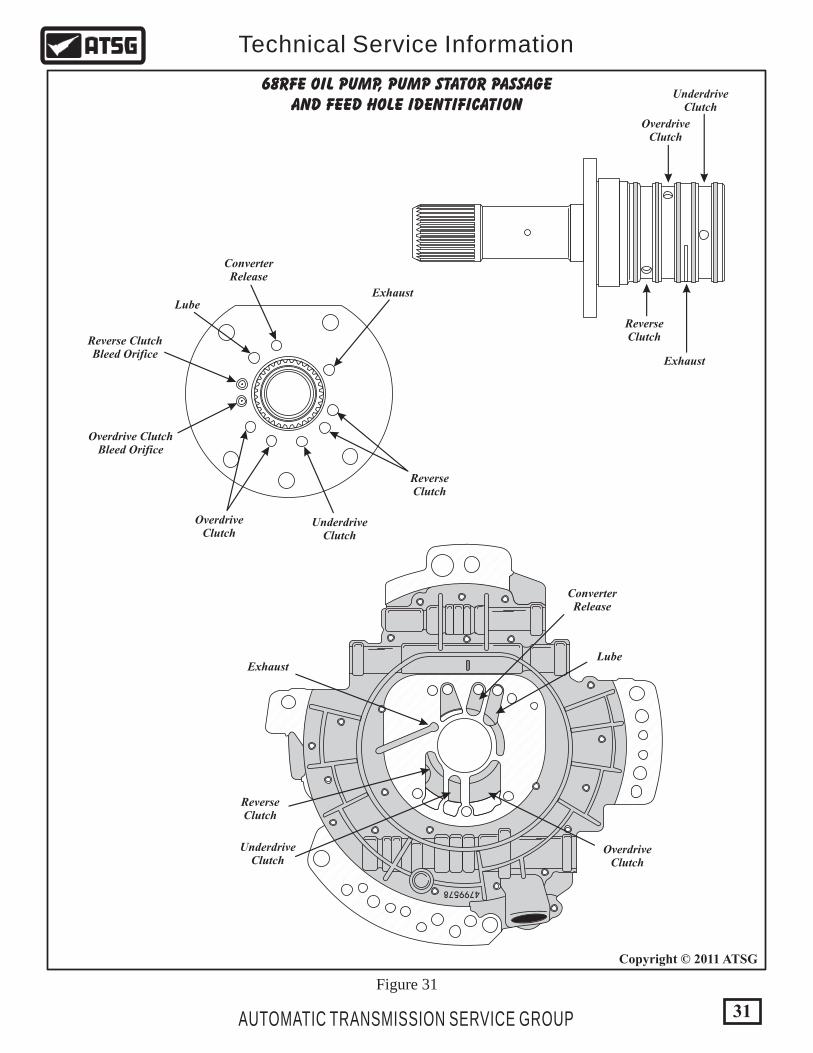
Figure 31
68RFE OIL PUMP, PUMP STATOR PASSAGEAND FEED HOLE IDENTIFICATION
OverdriveClutch
UnderdriveClutch
ReverseClutch
Exhaust
ReverseClutch
Reverse ClutchBleed Orifice
Overdrive ClutchBleed Orifice
OverdriveClutch
UnderdriveClutch
Exhaust
ConverterRelease
Lube
ReverseClutch
OverdriveClutch
UnderdriveClutch
Exhaust
ConverterRelease
Lube
4799578
31
Copyright © 2011 ATSG
AUTOMATIC TRANSMISSION SERVICE GROUP
Technical Service Information

TRANSMISSION DISASSEMBLY
Figure 33
Figure 32
1. Drain fluid from the transmission. 2. Clean exterior of the transmission thoroughly with a suitable solvent or pressure washer. 3. Remove torque converter from the transmission, as shown in Figure 33. Caution: Use care removing torque converter to prevent injury or damage as it is heavy. 4. Remove and discard the "O" ring from the converter hub, as shown in Figure 32.
SAFETY PRECAUTIONS Service information provided in this manual by ATSG is intended for use by professional, qualified technicians. Attempting repairs or service without the appropriate training, tools and equipment could cause injury to you or others. The service procedures we recommend and describe in this manual are effective methods of performing service and repair on this unit. Some of the procedures require the use of special tools that are designed for specific purposes. This manual contains CAUTIONS that you must observe carefully in order to reduce the risk of injury to yourself or others. This manual also contains NOTES that must be carefully followed in order to avoid improper service that may damage the vehicle, tools and/or equipment.
32 AUTOMATIC TRANSMISSION SERVICE GROUP
Technical Service Information
Copyright © 2011 ATSG
Copyright © 2011 ATSG 1 TORQUE CONVERTER ASSEMBLY.
1
"O" RING
Continued on Page 33
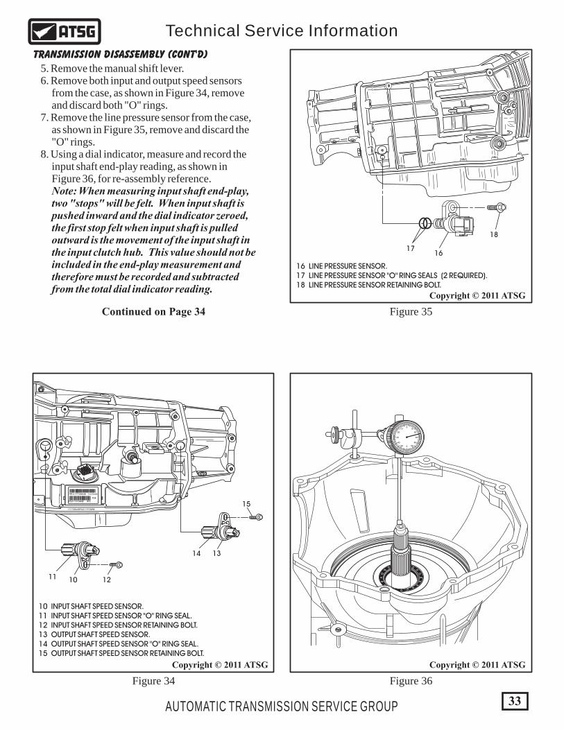
5. Remove the manual shift lever. 6. Remove both input and output speed sensors from the case, as shown in Figure 34, remove and discard both "O" rings. 7. Remove the line pressure sensor from the case, as shown in Figure 35, remove and discard the "O" rings. 8. Using a dial indicator, measure and record the input shaft end-play reading, as shown in Figure 36, for re-assembly reference. Note: When measuring input shaft end-play, two "stops" will be felt. When input shaft is pushed inward and the dial indicator zeroed, the first stop felt when input shaft is pulled outward is the movement of the input shaft in the input clutch hub. This value should not be included in the end-play measurement and therefore must be recorded and subtracted from the total dial indicator reading.
Figure 34
Figure 35
Figure 36
177720548P52119704AB
TITTJ177720548 14:10:44
P52119704AB RFE
704
10 1211
13
15
14
1617
18
Copyright © 2011 ATSG
Copyright © 2011 ATSG
16 LINE PRESSURE SENSOR. 17 LINE PRESSURE SENSOR "O" RING SEALS (2 REQUIRED). 18 LINE PRESSURE SENSOR RETAINING BOLT.
10 INPUT SHAFT SPEED SENSOR. 11 INPUT SHAFT SPEED SENSOR "O" RING SEAL. 12 INPUT SHAFT SPEED SENSOR RETAINING BOLT. 13 OUTPUT SHAFT SPEED SENSOR. 14 OUTPUT SHAFT SPEED SENSOR "O" RING SEAL. 15 OUTPUT SHAFT SPEED SENSOR RETAINING BOLT.
TRANSMISSION DISASSEMBLY (CONT'D)
33
Copyright © 2011 ATSG
AUTOMATIC TRANSMISSION SERVICE GROUP
Technical Service Information
0
0
1010
5050
2020
4040
3030
Continued on Page 34

177720548P52119704AB
TITTJ177720548 14:10:44
P52119704AB RFE
704
Figure 37
Figure 38
Continued on Page 35
190
191
192
193
SMALLBLOCKWOOD
190 PARK GEAR. 191 PARK GEAR RETAINING SNAP RING. 192 EXTENSION HOUSING BOLTS (12 REQUIRED). 193 EXTENSION HOUSING (MODEL SENSITIVE).
Copyright © 2011 ATSG
TRANSMISSION DISASSEMBLY (CONT'D)
9. Remove the 12 extension housing to case retaining bolts using a 15mm socket and then remove the extension housing, as shown in Figure 37. 10. Remove the park gear snap ring from the output shaft and remove the park gear, as shown in Figure 37. 11. Using a dial indicator, measure and record the output shaft end-play reading, as shown in Figure 38, to use as a reference for re-assembly. Note: Use screwdriver and small wood block to move gear train up and down, as shown in Figure 38.
0
0
1010
5050
2020
4040
3030
34
Copyright © 2011 ATSG
AUTOMATIC TRANSMISSION SERVICE GROUP
Technical Service Information

Figure 39
Figure 40
Figure 41
177720548P52119704AB
TITTJ177720548 14:10:44
P52119704AB RFE704
479965505111
AK 1
98
177720548P52119704AB
TITTJ177720548 14:10:44
P52119704AB RFE704
479965505111
AK 1
98
12. Remove the 15 bottom pan bolts, using an 8mm socket, as shown in Figure 39. 13. Remove bottom oil pan as shown in Figure 39. Note: The 68RFE uses no gaskets anywhere. The extension housing and pan are sealed with RTV
14. Remove the bottom pan filter retaining screw, using a 25 Torx bit, as shown in Figure 40. 15. Remove and discard the bottom pan oil filter, as shown in Figure 40. 16. Remove the six valve body retaining bolts using 8mm socket, as shown in Figure 41. 17. Remove the complete valve body and the TRS/Solenoid body as an assembly, as shown in Figure 41, and set aside for component rebuild section. Note: The valve body to case retaining bolt locations are shown in Figure 42.
Continued on Page 36
19 20
6 7 VALVE BODYASSEMBLY
6 OIL PAN BOLTS (15 REQUIRED). 7 OIL PAN ASSEMBLY.
19 MAIN OIL FILTER RETAINING BOLT. 20 MAIN OIL FILTER.
Copyright © 2011 ATSG Copyright © 2011 ATSG
TRANSMISSION DISASSEMBLY (CONT'D)
35
Copyright © 2011 ATSG
AUTOMATIC TRANSMISSION SERVICE GROUP
Technical Service Information
177720548P52119704AB
TITTJ177720548 14:10:44
P52119704AB RFE704
479965505111
AK 1
98

177720548P52119704AB
TITTJ177720548 14:10:44
P52119704AB RFE704
Figure 42
Figure 43
479965505111
AK 1
98
VALVE BODYRETAINING BOLTS
VALVE BODYRETAINING BOLT
VALVE BODYRETAINING BOLTS
22
21
21 COOLER FILTER. 22 COOLER FILTER BYPASS VALVE ASSEMBLY.
ENLARGEDVIEW
36
Copyright © 2011 ATSG
Copyright © 2011 ATSG
AUTOMATIC TRANSMISSION SERVICE GROUP
Technical Service Information
18. Remove and discard the cooler oil filter from the transmission case, as shown in Figure 43. 19. Remove the cooler by-pass valve assembly from the transmission case, as shown in Figure 43. Note: May need replacement depending on the degree of unit destruction and amount of debris that it contains.
TRANSMISSION DISASSEMBLY (CONT'D)
Continued on Page 37
12
34
56
78
91
011
Figure 45Figure 44
37
Copyright © 2011 ATSGCopyright © 2011 ATSG
AUTOMATIC TRANSMISSION SERVICE GROUP
Technical Service Information
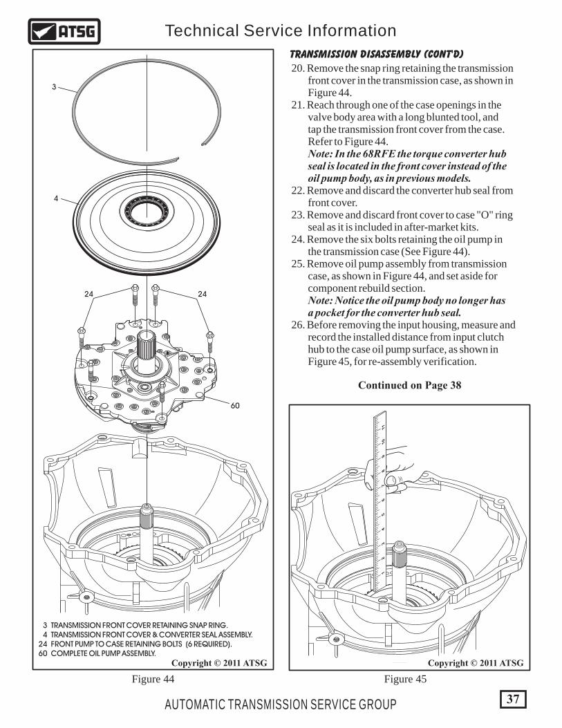
20. Remove the snap ring retaining the transmission front cover in the transmission case, as shown in Figure 44. 21. Reach through one of the case openings in the valve body area with a long blunted tool, and tap the transmission front cover from the case. Refer to Figure 44. Note: In the 68RFE the torque converter hub seal is located in the front cover instead of the oil pump body, as in previous models. 22. Remove and discard the converter hub seal from front cover. 23. Remove and discard front cover to case "O" ring seal as it is included in after-market kits. 24. Remove the six bolts retaining the oil pump in the transmission case (See Figure 44). 25. Remove oil pump assembly from transmission case, as shown in Figure 44, and set aside for component rebuild section. Note: Notice the oil pump body no longer has a pocket for the converter hub seal. 26. Before removing the input housing, measure and record the installed distance from input clutch hub to the case oil pump surface, as shown in Figure 45, for re-assembly verification.
Continued on Page 38
TRANSMISSION DISASSEMBLY (CONT'D)
102
3 TRANSMISSION FRONT COVER RETAINING SNAP RING. 4 TRANSMISSION FRONT COVER & CONVERTER SEAL ASSEMBLY. 24 FRONT PUMP TO CASE RETAINING BOLTS (6 REQUIRED). 60 COMPLETE OIL PUMP ASSEMBLY.
3
4
2424
60

27. Remove the input clutch housing assembly by lifting straight up, as shown in Figure 46. 28. Remove the number 1 thrust bearing from inside the input housing, as shown in Figure 46. 29. Remove number 5 thrust bearing and "selective" thrust bearing spacer, as shown in Figure 46. Note: Number 5 thrust bearing has 3 equally spaced "protrusions" around the outside diameter that snaps into the selective spacer, as shown in Figure 47. This selective spacer is used to set front transmission end-play. 30. Set the input clutch housing assembly aside for component rebuild section.
Continued on Page 39
TRANSMISSION DISASSEMBLY (CONT'D)
NUMBER 5THRUST BEARING
(131)
SELECTIVESPACER(132)
3 Equally Spaced "Protrusions"Around The Outside Diameter
Snaps Into Selective Spacer
NUMBER 5 THRUST BEARING
Figure 46 Figure 47
97
100
131
97 NUMBER 1 THRUST BEARING. 100 INPUT CLUTCH HOUSING ASSEMBLY. 131 NUMBER 5 THRUST BEARING AND "SELECTIVE" SPACER.
38
Copyright © 2011 ATSGCopyright © 2011 ATSG
AUTOMATIC TRANSMISSION SERVICE GROUP
Technical Service Information

Figure 49Figure 48
39
Copyright © 2011 ATSGCopyright © 2011 ATSG
AUTOMATIC TRANSMISSION SERVICE GROUP
Technical Service Information
31. Remove the 2-4 clutch retainer front snap ring, which is a tapered snap ring, from case as shown in Figure 48. 32. Remove the 2-4 clutch retainer from the case, as shown in Figure 48, and set aside for component rebuild section.
33. Remove the 2-4 clutch retainer rear snap ring, which is a flat snap ring from the case, as shown in Figure 48. 34. Remove the 2nd clutch pack, 3 steel plates and 3 friction plates, as shown in Figure 49. 35. Remove the 2nd clutch backing plate from the case, as shown in Figure 49.
Continued on Page 40
TRANSMISSION DISASSEMBLY (CONT'D)
151 SECOND CLUTCH STEEL PLATES (.130" THICK) (3 REQUIRED). 152 SECOND CLUTCH FRICTION PLATES (.090" THICK) (3 REQ). 153 SECOND CLUTCH BACKING PLATE (.325" THICK).
140 2-4 CLUTCH RETAINER ASSEMBLY. 154 2-4 RETAINER TO CASE "TAPERED" SNAP RING. 155 2-4 RETAINER TO CASE "FLAT" SNAP RING (.062" THICK). 156 NUMBER 6 THRUST BEARING.
155
154
156
140
153
152
151

Figure 50 Figure 51
36. Remove number 6 thrust bearing if it is present, as shown in Figure 50. It may have been stuck to the 2-4 clutch retainer. 37. Remove the 4th clutch hub and reaction sun gear along with the number 7 thrust washer, as shown in Figure 50. Note: 68RFE does not use a number 7 thrust "bearing" because the sun gear is now part of the 4th clutch hub. We have renumbered the washer to number 7 to keep the numbers in sequence and it is the selective for setting the transmission rear end-play.
38. Remove the number 8 thrust bearing and the reaction carrier/reverse sun gear, as shown in Figure 51. Note: You will notice all planetary carriers are now 6 pinion carriers in this unit. 39. Remove the number 9 thrust bearing, as shown in Figure 51. Note: Number 9 thrust bearing may be stuck back side of sun gear.
Continued on Page 41
TRANSMISSION DISASSEMBLY (CONT'D)
160 NUMBER 8 THRUST BEARING. 162 REACTION CARRIER & REVERSE SUN GEAR ASSEMBLY. 163 NUMBER 9 THRUST BEARING.
156 NUMBER 6 THRUST BEARING. 157 NUMBER 7 "SELECTIVE" THRUST WASHER (REAR END-PLAY). 159 FOURTH CLUTCH HUB & REACTION SUN GEAR ASSEMBLY.
156
157
159
160
162
163
40
Copyright © 2011 ATSGCopyright © 2011 ATSG
AUTOMATIC TRANSMISSION SERVICE GROUP
Technical Service Information

Figure 53
40. Remove the complete planetary geartrain as an assembly, as shown in Figure 52, and set aside for component rebuild section. 41. Remove the number 12 thrust bearing, as shown in Figure 53. Note: Number 12 thrust bearing may be stuck to back side of output shaft.
42. Remove the low sprag assembly, as shown in Figure 53, and set aside for component rebuild section.
Figure 52
41
Copyright © 2011 ATSGCopyright © 2011 ATSG
AUTOMATIC TRANSMISSION SERVICE GROUP
Technical Service Information
TRANSMISSION DISASSEMBLY (CONT'D)
COMPLETEGEARTRAINASSEMBLY
Continued on Page 42
172
185
172 NUMBER 12 THRUST BEARING. 185 COMPLETE LOW SPRAG ASSEMBLY.

174
176
174 LOW/REV CLUTCH HOUSING TO CASE "TAPERED" SNAP RING. 176 COMPLETE LOW/REVERSE CLUTCH HOUSING.
43. Remove the "tapered" snap ring from the case that retains the low/reverse clutch housing in transmission case, as shown in Figure 54. 44. Remove the complete low/reverse clutch housing from the case, as shown in Figure 54, and set aside for component rebuild.
TRANSMISSION DISASSEMBLY (CONT'D)
Continued on Page 43
Figure 54
Figure 55
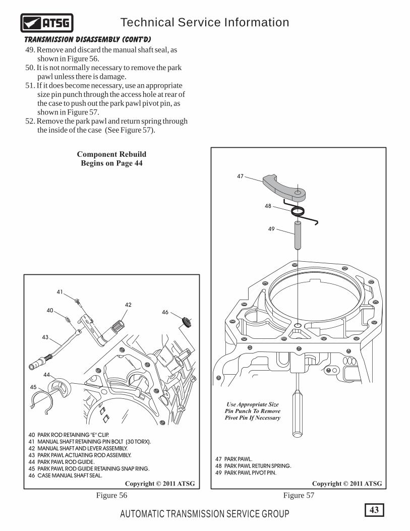
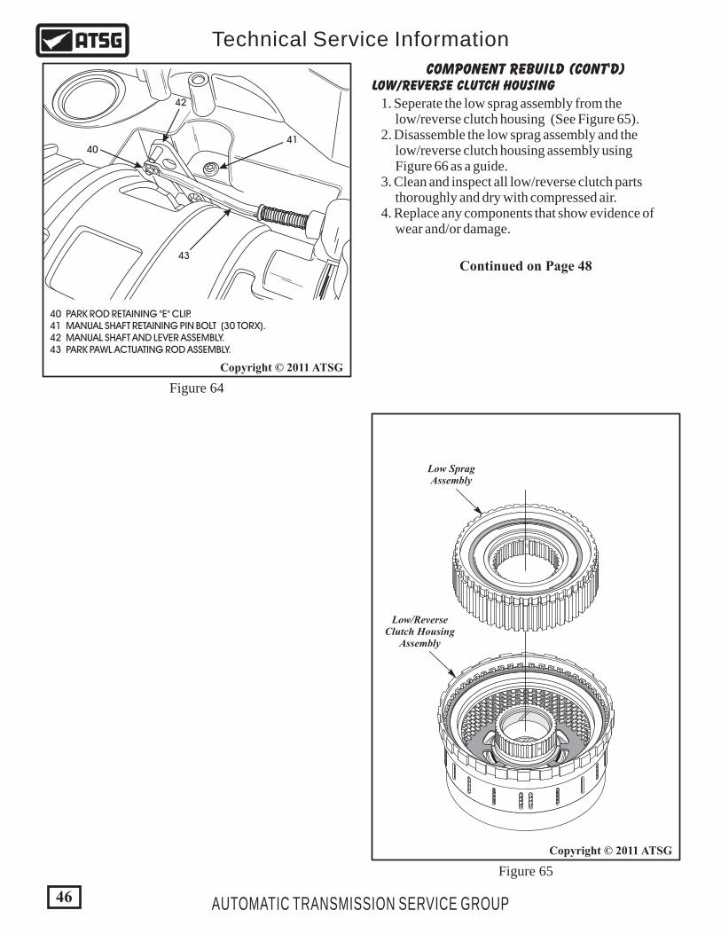
45. Remove the park actuating rod "E" clip from the manual lever, as shown in Figure 55 and 56. 46. Remove the park actuating rod assembly from transmission, as shown in Figure 55 and 56. 47. Remove the manual shaft and lever assembly retaining pin bolt using a 30 Torx bit, as shown in Figure 55 and 56. 48. Remove the manual shaft and lever assembly through the inside of case (See Figure 55 & 56).
40 PARK ROD RETAINING "E" CLIP. 41 MANUAL SHAFT RETAINING PIN BOLT (30 TORX). 42 MANUAL SHAFT AND LEVER ASSEMBLY. 43 PARK PAWL ACTUATING ROD ASSEMBLY.
4041
42
43
42
Copyright © 2011 ATSG
Copyright © 2011 ATSG
AUTOMATIC TRANSMISSION SERVICE GROUP
Technical Service Information
47 PARK PAWL. 48 PARK PAWL RETURN SPRING. 49 PARK PAWL PIVOT PIN.
40 PARK ROD RETAINING "E" CLIP. 41 MANUAL SHAFT RETAINING PIN BOLT (30 TORX). 42 MANUAL SHAFT AND LEVER ASSEMBLY. 43 PARK PAWL ACTUATING ROD ASSEMBLY. 44 PARK PAWL ROD GUIDE. 45 PARK PAWL ROD GUIDE RETAINING SNAP RING. 46 CASE MANUAL SHAFT SEAL.
40
41
42
46
43
44
45
Figure 56 Figure 57
47
48
49
Use Appropriate SizePin Punch To RemovePivot Pin If Necessary
TRANSMISSION DISASSEMBLY (CONT'D)
Component RebuildBegins on Page 44
49. Remove and discard the manual shaft seal, as shown in Figure 56. 50. It is not normally necessary to remove the park pawl unless there is damage. 51. If it does become necessary, use an appropriate size pin punch through the access hole at rear of the case to push out the park pawl pivot pin, as shown in Figure 57. 52. Remove the park pawl and return spring through the inside of the case (See Figure 57).
43
Copyright © 2011 ATSGCopyright © 2011 ATSG
AUTOMATIC TRANSMISSION SERVICE GROUP
Technical Service Information

46 CASE MANUAL SHAFT SEAL.
193 EXTENSION HOUSING (MODEL SENSITIVE). 194 OUTPUT SHAFT BALL BEARING. 195 OUTPUT SHAFT BALL BEARING RETAINING SNAP RING. 196 EXTENSION HOUSING SEAL (MODEL SENSITIVE).
44
Copyright © 2011 ATSG
Copyright © 2011 ATSGCopyright © 2011 ATSG
AUTOMATIC TRANSMISSION SERVICE GROUP
Technical Service Information
COMPONENT REBUILDEXTENSION HOUSING OR 4WD ADAPTER
TRANSMISSION CASE ASSEMBLY
195
194
193
196
COMPLETED EXTENSION HOUSING
Figure 58
Figure 59
Figure 60
1. Install new extension housing seal, as shown in Figure 58, using the proper seal driver. Note: 4WD Adapter shown, but procedure is the same for 2WD models. 2. Install new output shaft ball bearing assembly as necessary, as shown in Figure 58. 3. Install the ball bearing retaining snap ring, as shown in Figure 58. 4. Set the completed extension housing or 4WD adapter aside for the final assembly process.
1. Install new case manual shaft seal into the case, as shown in Figure 60, using the proper driver. 2. Lubricate the installed seal with a small amount of Trans-Jel®.
46
Continued on Page 45

47 PARK PAWL. 48 PARK PAWL RETURN SPRING. 49 PARK PAWL PIVOT PIN.
47
48PARK ACTUATING ROD
SEATED PROPERLY
49
45
Copyright © 2011 ATSG
Copyright © 2011 ATSG
Copyright © 2011 ATSG
AUTOMATIC TRANSMISSION SERVICE GROUP
Technical Service Information
40 PARK ROD RETAINING "E" CLIP. 41 MANUAL SHAFT RETAINING PIN BOLT (30 TORX). 42 MANUAL SHAFT AND LEVER ASSEMBLY. 43 PARK PAWL ACTUATING ROD ASSEMBLY. 44 PARK PAWL ROD GUIDE. 45 PARK PAWL ROD GUIDE RETAINING SNAP RING. 46 CASE MANUAL SHAFT SEAL.
40
41
42
46
43
44
45
Figure 61 Figure 63
Figure 62
TRANSMISSION CASE ASSEMBLY (CONT'D)
3. Install the park pawl and park pawl return spring through back of case into position, and insert the pivot pin, as shown in Figure 61. 4. Install the park rod guide into the transmission case, as shown in Figure 62. 5. Install the park rod guide retaining snap ring in case groove using a pair of pliers and ensure that it is fully seated (See Figure 62). 6. Install manual shaft and lever assembly through the inside of case and into the manual shaft case bore, as shown in Figure 62. 7. Install manual shaft and lever assembly retaining pin bolt, using a 30 torx bit and torque the bolt 28 N·m (20 ft.lb.). (See Figure 62 and 64). 8. Install park actuating rod assembly through park rod guide and parking pawl, and onto the pin on manual lever (See Figure 62 and 64). Note: Ensure that park actuating rod is seated between park pawl and park guide, as shown in Figure 63. 9. Install the park rod retaining "E" clip and insure that is is fully seated, as shown in Figure 64.
Component RebuildContinued on Page 46
10. Ensure that parking linkage is working properly and set case aside for the final assembly process.
40 PARK ROD RETAINING "E" CLIP. 41 MANUAL SHAFT RETAINING PIN BOLT (30 TORX). 42 MANUAL SHAFT AND LEVER ASSEMBLY. 43 PARK PAWL ACTUATING ROD ASSEMBLY.
4041
42
43
Figure 65
Figure 64
LOW/REVERSE CLUTCH HOUSING
Continued on Page 48
1. Seperate the low sprag assembly from the low/reverse clutch housing (See Figure 65). 2. Disassemble the low sprag assembly and the low/reverse clutch housing assembly using Figure 66 as a guide. 3. Clean and inspect all low/reverse clutch parts thoroughly and dry with compressed air. 4. Replace any components that show evidence of wear and/or damage.
COMPONENT REBUILD (CONT'D)
Low SpragAssembly
Low/ReverseClutch Housing
Assembly
46
Copyright © 2011 ATSG
Copyright © 2011 ATSG
AUTOMATIC TRANSMISSION SERVICE GROUP
Technical Service Information
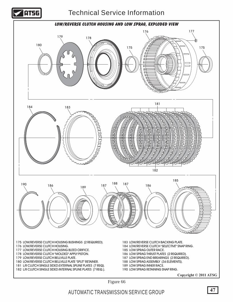
Figure 66
175
177176
178179
180
181
182
185
186186 187 187188190
183184
175
LOW/REVERSE CLUTCH HOUSING AND LOW SPRAG, EXPLODED VIEW
189
175 LOW/REVERSE CLUTCH HOUSING BUSHINGS (2 REQUIRED). 176 LOW/REVERSE CLUTCH HOUSING. 177 LOW/REVERSE CLUTCH HOUSING BLEED ORIFICE. 178 LOW/REVERSE CLUTCH "MOLDED" APPLY PISTON. 179 LOW/REVERSE CLUTCH BELLVILLE PLATE. 180 LOW/REVERSE CLUTCH BELLVILLE PLATE "SPLIT" RETAINER. 181 L/R CLUTCH SINGLE SIDED EXTERNAL SPLINE PLATES (7 REQ). 182 L/R CLUTCH SINGLE SIDED INTERNAL SPLINE PLATES (7 REQ.).
183 LOW/REVERSE CLUTCH BACKING PLATE. 184 LOW/REVERSE CLUTCH "SELECTIVE" SNAP RING. 185 LOW SPRAG OUTER RACE. 186 LOW SPRAG THRUST PLATES (2 REQUIRED). 187 LOW SPRAG END BREARINGS (2 REQUIRED). 188 LOW SPRAG ASSEMBLY (36 ELEMENTS). 189 LOW SPRAG INNER RACE. 190 LOW SPRAG RETAINING SNAP RING.
47
Copyright © 2011 ATSG
AUTOMATIC TRANSMISSION SERVICE GROUP
Technical Service Information
185185
186
187
"WINDOWS"FACING LEFT
"WINDOWS"FACING LEFT
"CHANNELS"FACING UP
"CHANNELS"FACING UP
187
188
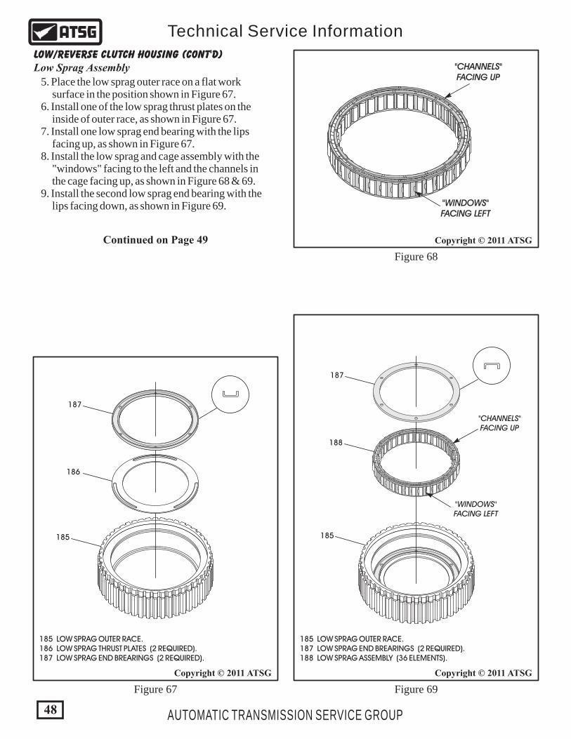
185 LOW SPRAG OUTER RACE. 187 LOW SPRAG END BREARINGS (2 REQUIRED). 188 LOW SPRAG ASSEMBLY (36 ELEMENTS).
185 LOW SPRAG OUTER RACE. 186 LOW SPRAG THRUST PLATES (2 REQUIRED). 187 LOW SPRAG END BREARINGS (2 REQUIRED).
48
Copyright © 2011 ATSG
Copyright © 2011 ATSG
Copyright © 2011 ATSG
AUTOMATIC TRANSMISSION SERVICE GROUP
Technical Service Information
LOW/REVERSE CLUTCH HOUSING (CONT'D)
Continued on Page 49
5. Place the low sprag outer race on a flat work surface in the position shown in Figure 67. 6. Install one of the low sprag thrust plates on the inside of outer race, as shown in Figure 67. 7. Install one low sprag end bearing with the lips facing up, as shown in Figure 67. 8. Install the low sprag and cage assembly with the "windows" facing to the left and the channels in the cage facing up, as shown in Figure 68 & 69. 9. Install the second low sprag end bearing with the lips facing down, as shown in Figure 69.
Figure 68
Figure 69Figure 67
Low Sprag Assembly
186
190
189
RECESSFACING UP
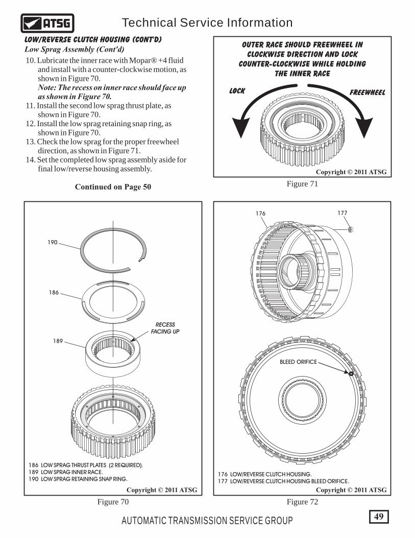
186 LOW SPRAG THRUST PLATES (2 REQUIRED). 189 LOW SPRAG INNER RACE. 190 LOW SPRAG RETAINING SNAP RING.
FREEWHEELLOCK
OUTER RACE SHOULD FREEWHEEL INCLOCKWISE DIRECTION AND LOCK
COUNTER-CLOCKWISE WHILE HOLDINGTHE INNER RACE
BLEED ORIFICE
177176
176 LOW/REVERSE CLUTCH HOUSING. 177 LOW/REVERSE CLUTCH HOUSING BLEED ORIFICE.
49
Copyright © 2011 ATSG
Copyright © 2011 ATSG
Copyright © 2011 ATSG
AUTOMATIC TRANSMISSION SERVICE GROUP
Technical Service Information
LOW/REVERSE CLUTCH HOUSING (CONT'D)
Continued on Page 50
10. Lubricate the inner race with Mopar® +4 fluid and install with a counter-clockwise motion, as shown in Figure 70. Note: The recess on inner race should face up as shown in Figure 70. 11. Install the second low sprag thrust plate, as shown in Figure 70. 12. Install the low sprag retaining snap ring, as shown in Figure 70. 13. Check the low sprag for the proper freewheel direction, as shown in Figure 71. 14. Set the completed low sprag assembly aside for final low/reverse housing assembly.
Figure 72
Figure 71
Figure 70
Low Sprag Assembly (Cont'd)

176 LOW/REVERSE CLUTCH HOUSING. 178 LOW/REVERSE CLUTCH "MOLDED" APPLY PISTON. 179 LOW/REVERSE CLUTCH BELLVILLE PLATE. 180 LOW/REVERSE CLUTCH BELLVILLE PLATE "SPLIT" RETAINER RING.
176
178
179
180
LOW/REVERSE CLUTCH HOUSING (CONT'D)
Continued on Page 51
15. Check the bleed orifice in the bottom of the low/reverse clutch housing to ensure that it is still there, as shown in Figure 72, and that it is not plugged, restricted or blown out. 16. Set the low/reverse clutch housing on a flat work surface, as shown in Figure 73. 17. Lubricate the inner and outer seal surfaces of the "molded" piston and the housing with small amount of Trans-Jel®.
18. Install low/reverse clutch piston into low/reverse clutch housing, as shown in Figure 73. 19. Install the bellville type return spring on top of the installed piston in the direction that is shown in Figure 73. 20. Compress bellville spring and install the "split" retainer into the groove of housing, as shown in Figure 73. 21. The "Drum-Buddy" from Adapt-A-Case works very well, on a wide variety of units, and is shown in Figure 74.
Figure 73 Figure 74
AP
-AA
DAT
-CES
"THE DRUM BUDDY" BY ADAPT-A-CASE
50
Copyright © 2011 ATSGCopyright © 2011 ATSG
AUTOMATIC TRANSMISSION SERVICE GROUP
Technical Service Information

181 L/R CLUTCH SINGLE SIDED EXTERNAL SPLINE PLATES (7 REQ). 182 L/R CLUTCH SINGLE SIDED INTERNAL SPLINE PLATES (7 REQ.). 183 LOW/REVERSE CLUTCH BACKING PLATE. 184 LOW/REVERSE CLUTCH "SELECTIVE" SNAP RING.
181182
183
STEPFACING UP
184
LOW/REVERSE CLUTCH CLEARANCE SHOULD BE1.18 - 2.09 MM (.046" - .082")
51
Copyright © 2011 ATSGCopyright © 2011 ATSG
AUTOMATIC TRANSMISSION SERVICE GROUP
Technical Service Information
LOW/REVERSE CLUTCH HOUSING (CONT'D)
Continued on Page 52
22. Install the "single-sided" low/reverse clutch plates beginning with an outside spline plate and alternate with inside spline plates, until you have installed 7 of each, as shown in Figure 75. Note: All "single-sided" plates are installed with the lining facing up and should be soaked for 30 minutes in Mopar® +4 fluid before they are installed. 23. Install the low/reverse clutch backing plate with the step facing up, as shown in Figure 75. 24. Install the low/reverse clutch selective snap ring, as shown in Figure 75. 25. Turn completed housing over and tap on work bench to seat the snap ring at the top of groove. 26. Measure the low/reverse clutch clearance using a feeler gauge between the snap ring and backing plate, as shown in Figure 76. 27. The low/reverse clutch clearance should be 1.18-2.09mm (.046"-.082"). 28. Change the selective snap ring as necessary to obtain the correct clutch clearance. Note: We have no information on selectives available or their thickness. 29. Once the proper selective snap ring has been verified, remove the low/reverse clutch pack from the housing.
Figure 75 Figure 76
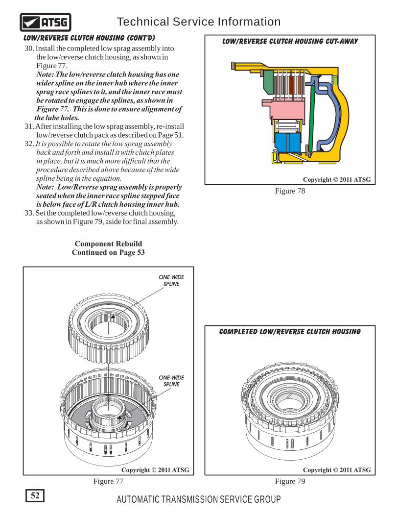
COMPLETED LOW/REVERSE CLUTCH HOUSING
LOW/REVERSE CLUTCH HOUSING CUT-AWAY
ONE WIDESPLINE
ONE WIDESPLINE
52
Copyright © 2011 ATSG
Copyright © 2011 ATSG
Copyright © 2011 ATSG
AUTOMATIC TRANSMISSION SERVICE GROUP
Technical Service Information
Figure 77 Figure 79
Figure 78
LOW/REVERSE CLUTCH HOUSING (CONT'D)
Component RebuildContinued on Page 53
30. Install the completed low sprag assembly into the low/reverse clutch housing, as shown in Figure 77. Note: The low/reverse clutch housing has one wider spline on the inner hub where the inner sprag race splines to it, and the inner race must be rotated to engage the splines, as shown in Figure 77. This is done to ensure alignment of the lube holes. 31. After installing the low sprag assembly, re-install low/reverse clutch pack as described on Page 51. 32. It is possible to rotate the low sprag assembly back and forth and install it with clutch plates in place, but it is much more difficult that the procedure described above because of the wide spline being in the equation. Note: Low/Reverse sprag assembly is properly seated when the inner race spline stepped face is below face of L/R clutch housing inner hub. 33. Set the completed low/reverse clutch housing, as shown in Figure 79, aside for final assembly.

53
Copyright © 2011 ATSG
AUTOMATIC TRANSMISSION SERVICE GROUP
Technical Service Information
140 2-4 CLUTCH RETAINER ASSEMBLY. 141 SECOND CLUTCH "MOLDED" APPLY PISTON ASSEMBLY 142 SECOND CLUTCH BELLVILLE PLATE. 143 SECOND CLUTCH BELLVILLE PLATE RETAINING SNAP RING. 144 FOURTH CLUTCH "MOLDED" APPLY PISTON ASSEMBLY. 145 FOURTH CLUTCH PISTON RETURN SPRING ASSEMBLY.
146 FOURTH CLUTCH RETURN SPRING SNAP RING. 147 FOURTH CLUTCH STEEL PLATES, (.101" THICK) (3 REQUIRED). 148 FOURTH CLUTCH FRICTION PLATES, (.087" THICK) (3 REQ.). 149 FOURTH CLUTCH BACKING PLATE, (.197" THICK). 150 FOURTH CLUTCH "SELECTIVE" BACKING PLATE SNAP RING. 154 NUMBER 6 THRUST BEARING.
140141142143
144
145
149150
154 146
147
148
2-4 CLUTCH RETAINER EXPLODED VIEW
2-4 CLUTCH RETAINER ASSEMBLY
Continued on Page 54
1. Disassemble the 2-4 clutch retainer assembly using Figure 80 as a guide. 2. Clean all 2-4 clutch retainer parts thoroughly and dry with compressed air.
3. Inspect all 2-4 clutch retainer parts thoroughly for any wear and/or damage and replace as necessary.
COMPONENT REBUILD (CONT'D)
Figure 80
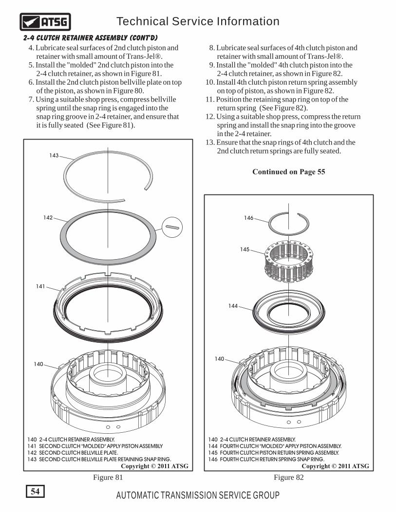
140 2-4 CLUTCH RETAINER ASSEMBLY. 141 SECOND CLUTCH "MOLDED" APPLY PISTON ASSEMBLY 142 SECOND CLUTCH BELLVILLE PLATE. 143 SECOND CLUTCH BELLVILLE PLATE RETAINING SNAP RING.
140 2-4 CLUTCH RETAINER ASSEMBLY. 144 FOURTH CLUTCH "MOLDED" APPLY PISTON ASSEMBLY. 145 FOURTH CLUTCH PISTON RETURN SPRING ASSEMBLY. 146 FOURTH CLUTCH RETURN SPRING SNAP RING.
140140
144
145
146
141
142
143
2-4 CLUTCH RETAINER ASSEMBLY (CONT'D)
Continued on Page 55
4. Lubricate seal surfaces of 2nd clutch piston and retainer with small amount of Trans-Jel®. 5. Install the "molded" 2nd clutch piston into the 2-4 clutch retainer, as shown in Figure 81. 6. Install the 2nd clutch piston bellville plate on top of the piston, as shown in Figure 80. 7. Using a suitable shop press, compress bellville spring until the snap ring is engaged into the snap ring groove in 2-4 retainer, and ensure that it is fully seated (See Figure 81).
8. Lubricate seal surfaces of 4th clutch piston and retainer with small amount of Trans-Jel®. 9. Install the "molded" 4th clutch piston into the 2-4 clutch retainer, as shown in Figure 82. 10. Install 4th clutch piston return spring assembly on top of piston, as shown in Figure 82. 11. Position the retaining snap ring on top of the return spring (See Figure 82). 12. Using a suitable shop press, compress the return spring and install the snap ring into the groove in the 2-4 retainer. 13. Ensure that the snap rings of 4th clutch and the 2nd clutch return springs are fully seated.
Figure 81 Figure 82
54
Copyright © 2011 ATSGCopyright © 2011 ATSG
AUTOMATIC TRANSMISSION SERVICE GROUP
Technical Service Information
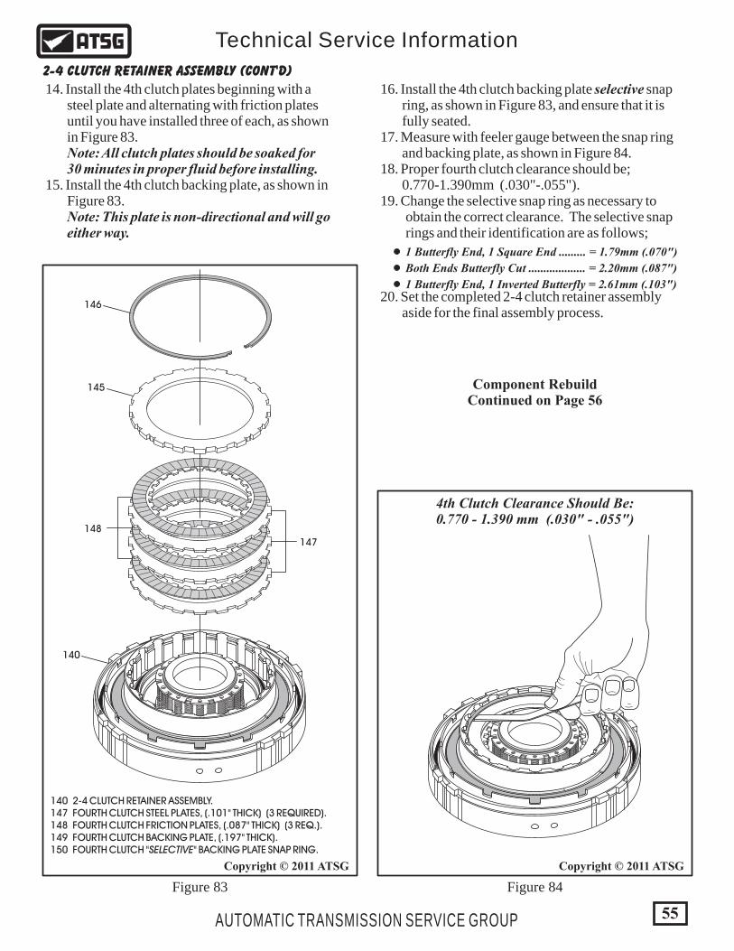
16. Install the 4th clutch backing plate selective snap ring, as shown in Figure 83, and ensure that it is fully seated. 17. Measure with feeler gauge between the snap ring and backing plate, as shown in Figure 84. 18. Proper fourth clutch clearance should be; 0.770-1.390mm (.030"-.055"). 19. Change the selective snap ring as necessary to obtain the correct clearance. The selective snap rings and their identification are as follows;
20. Set the completed 2-4 clutch retainer assembly aside for the final assembly process.
140
147
148
145
146
140 2-4 CLUTCH RETAINER ASSEMBLY. 147 FOURTH CLUTCH STEEL PLATES, (.101" THICK) (3 REQUIRED). 148 FOURTH CLUTCH FRICTION PLATES, (.087" THICK) (3 REQ.). 149 FOURTH CLUTCH BACKING PLATE, (.197" THICK). 150 FOURTH CLUTCH "SELECTIVE" BACKING PLATE SNAP RING.
4th Clutch Clearance Should Be:0.770 - 1.390 mm (.030" - .055")
1 Butterfly End, 1 Square End ......... = 1.79mm (.070")
Both Ends Butterfly Cut ................... = 2.20mm (.087")
1 Butterfly End, 1 Inverted Butterfly = 2.61mm (.103")
55
Copyright © 2011 ATSGCopyright © 2011 ATSG
AUTOMATIC TRANSMISSION SERVICE GROUP
Technical Service Information
Figure 83 Figure 84
2-4 CLUTCH RETAINER ASSEMBLY (CONT'D)
Component RebuildContinued on Page 56
14. Install the 4th clutch plates beginning with a steel plate and alternating with friction plates until you have installed three of each, as shown in Figure 83. Note: All clutch plates should be soaked for 30 minutes in proper fluid before installing. 15. Install the 4th clutch backing plate, as shown in Figure 83. Note: This plate is non-directional and will go either way.
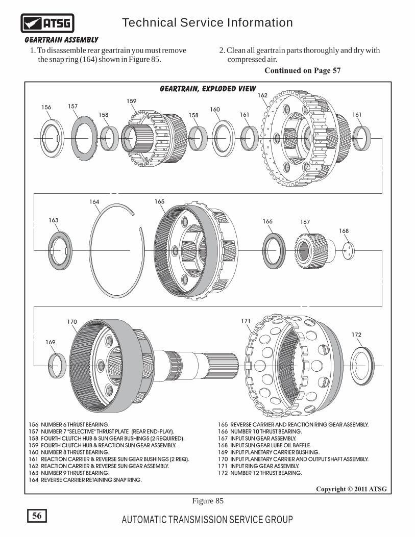
GEARTRAIN, EXPLODED VIEW
156 157
158 158160
161 161
162
163
169
170 171
172
164 165
166 167
168
159
156 NUMBER 6 THRUST BEARING. 157 NUMBER 7 "SELECTIVE" THRUST PLATE (REAR END-PLAY). 158 FOURTH CLUTCH HUB & SUN GEAR BUSHINGS (2 REQUIRED). 159 FOURTH CLUTCH HUB & REACTION SUN GEAR ASSEMBLY. 160 NUMBER 8 THRUST BEARING. 161 REACTION CARRIER & REVERSE SUN GEAR BUSHINGS (2 REQ). 162 REACTION CARRIER & REVERSE SUN GEAR ASSEMBLY. 163 NUMBER 9 THRUST BEARING. 164 REVERSE CARRIER RETAINING SNAP RING.
165 REVERSE CARRIER AND REACTION RING GEAR ASSEMBLY. 166 NUMBER 10 THRUST BEARING. 167 INPUT SUN GEAR ASSEMBLY. 168 INPUT SUN GEAR LUBE OIL BAFFLE. 169 INPUT PLANETARY CARRIER BUSHING. 170 INPUT PLANETARY CARRIER AND OUTPUT SHAFT ASSEMBLY. 171 INPUT RING GEAR ASSEMBLY. 172 NUMBER 12 THRUST BEARING.
56
Copyright © 2011 ATSG
AUTOMATIC TRANSMISSION SERVICE GROUP
Technical Service Information
Figure 85
GEARTRAIN ASSEMBLY
1. To disassemble rear geartrain you must remove the snap ring (164) shown in Figure 85.
2. Clean all geartrain parts thoroughly and dry with compressed air.
Continued on Page 57

156 NUMBER 6 THRUST BEARING. 157 NUMBER 7 "SELECTIVE" THRUST PLATE (REAR END-PLAY). 158 FOURTH CLUTCH HUB & SUN GEAR BUSHINGS (2 REQUIRED). 159 FOURTH CLUTCH HUB & REACTION SUN GEAR ASSEMBLY. 160 NUMBER 8 THRUST BEARING.
THIS SIDE FACESDOWN
156
ENSURE WASHER ISSEATED AND ENGAGEDWITH LOCATING PINS
157
158
158
159
160
COMPLETED 4TH CLUTCH HUBAND SUN GEAR
57
Copyright © 2011 ATSGCopyright © 2011 ATSG
AUTOMATIC TRANSMISSION SERVICE GROUP
Technical Service Information
GEARTRAIN ASSEMBLY (CONT'D)
3. Inspect all geartrain parts thoroughly for any wear and/or damage and replace as necessary. Note: Notice that all planetary carriers are now 6 pinion carriers to accommodate the Diesel engine. 4. Install number 7 selective thrust washer into 4th clutch hub/reaction sun gear with the "grooved" side facing down, as shown in Figure 86, and ensure it is fully seated over the locating tabs. Note: Because of the 68RFE design changes in the geartrain, engineers were able to eliminate the number 7 thrust bearing. ATSG has now assigned that number to this selective thrust washer which is used to set the transmission rear end-play. 5. Retain the number 7 selective thrust washer with small amount of Trans-Jel®.
6. Install the number 6 thrust bearing on top of the number 7 selective thrust washer in the direction shown in Figure 86 and retain with small amount of Trans-Jel®. 7. Double check to ensure that number 7 selective thrust washer and number 6 thrust bearing are properly seated, as shown in Figure 87, and set the completed 4th clutch hub/reaction sun gear aside for the final assembly process.
Figure 86 Figure 87
Continued on Page 58
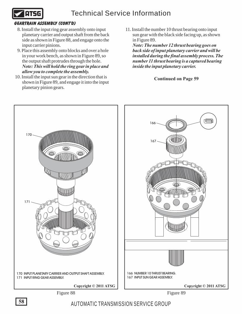
58
Copyright © 2011 ATSGCopyright © 2011 ATSG
AUTOMATIC TRANSMISSION SERVICE GROUP
Technical Service Information
GEARTRAIN ASSEMBLY (CONT'D)
8. Install the input ring gear assembly onto input planetary carrier and output shaft from the back side as shown in Figure 88, and engage onto the input carrier pinions. 9. Place this assembly onto blocks and over a hole in your work bench, as shown in Figure 89, so the output shaft protrudes through the hole. Note: This will hold the ring gear in place and allow you to complete the assembly. 10. Install the input sun gear in the direction that is shown in Figure 89, and engage it into the input planetary pinion gears.
11. Install the number 10 thrust bearing onto input sun gear with the black side facing up, as shown in Figure 89. Note: The number 12 thrust bearing goes on back side of input planetary carrier and will be installed during the final assembly process. The number 11 thrust bearing is a captured bearing inside the input planetary carrier.
Continued on Page 59
Figure 88 Figure 89
166 NUMBER 10 THRUST BEARING. 167 INPUT SUN GEAR ASSEMBLY.
166
167
170
171
170 INPUT PLANETARY CARRIER AND OUTPUT SHAFT ASSEMBLY. 171 INPUT RING GEAR ASSEMBLY.
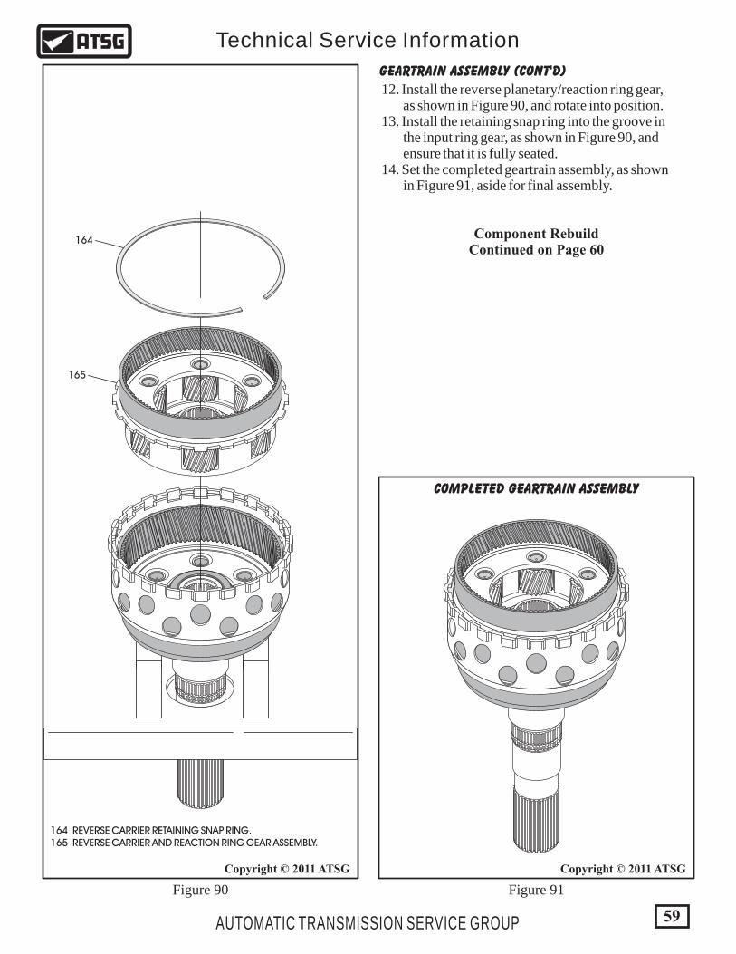
COMPLETED GEARTRAIN ASSEMBLY
59
Copyright © 2011 ATSGCopyright © 2011 ATSG
AUTOMATIC TRANSMISSION SERVICE GROUP
Technical Service Information
164 REVERSE CARRIER RETAINING SNAP RING. 165 REVERSE CARRIER AND REACTION RING GEAR ASSEMBLY.
164
165
Figure 90 Figure 91
GEARTRAIN ASSEMBLY (CONT'D)
Component RebuildContinued on Page 60
12. Install the reverse planetary/reaction ring gear, as shown in Figure 90, and rotate into position. 13. Install the retaining snap ring into the groove in the input ring gear, as shown in Figure 90, and ensure that it is fully seated. 14. Set the completed geartrain assembly, as shown in Figure 91, aside for final assembly.
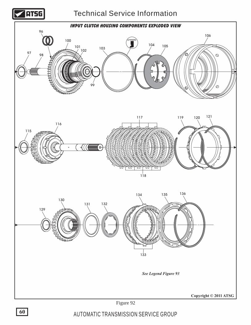
Figure 92
INPUT CLUTCH HOUSING COMPONENTS EXPLODED VIEW
97
96
98
99
115
116
119 120 121
129
130131 132
133
134 135 136
117
118
100
101102
103104 105
106
See Legend Figure 93
60
Copyright © 2011 ATSG
AUTOMATIC TRANSMISSION SERVICE GROUP
Technical Service Information
4799090

Figure 93
INPUT CLUTCH HOUSING COMPONENTS EXPLODED VIEW
4799090107
122
123
124
125
126 127 128
108
109
110
111
112113
114
118 UD CLUTCH SINGLE-SIDED, INTERNAL SPLINE PLATES (5 REQ.). 119 UNDERDRIVE/OVERDRIVE BACKING PLATE "FLAT" SNAP RING. 120 UNDERDRIVE/OVERDRIVE BACKING PLATE. 121 UNDERDRIVE/OD BACKING PLATE "TAPERED" SNAP RING. 122 NUMBER 3 THRUST BEARING. 123 OVERDRIVE CLUTCH HUB AND SHAFT ASSEMBLY. 124 OD CLUTCH SINGLE SIDED, EXTERNAL SPLINE PLATES (6 REQ.). 125 OD CLUTCH SINGLE SIDED, INTERNAL SPLINE PLATES (6 REQ.). 126 OVERDRIVE/REVERSE BACKING PLATE "WAVE" SNAP RING. 127 OVERDRIVE/REVERSE "SELECTIVE" BACKING PLATE. 128 OVERDRIVE/REVERSE BACKING PLATE "FLAT" SNAP RING. 129 NUMBER 4 THRUST BEARING. 130 REVERSE CLUTCH HUB ASSEMBLY. 131 NUMBER 5 THRUST BEARING. 132 NUMBER 5 "SELECTIVE" THRUST BEARING SPACER. 133 REVERSE CLUTCH FRICTION PLATES, .080" THICK (2 REQ.). 134 REVERSE CLUTCH STEEL PLATE, .067" THICK (1 REQUIRED). 135 REVERSE CLUTCH BACKING PLATE. 136 REVERSE CLUTCH BACKING PLATE "SELECTIVE" SNAP RING. 137 DRAIN BACK BALL CAPSULE RETAINING SNAP RING. 138 DRAIN BACK BALL CAPSULE. 139 DRAIN BACK BALL CAPSULE "O" RING SEAL.
96 INPUT SHAFT SEAL RINGS (2 REQUIRED). 97 NUMBER 1 THRUST BEARING. 98 INPUT SHAFT. 99 INPUT SHAFT RETAINING CIR-CLIP. 100 INPUT CLUTCH HUB. 101 GREEN COLORED "O" RING SEAL. 102 RED COLORED "O" RING SEAL. 103 REVERSE OUTER LIP SEAL (INSIDE LIP). 104 OVERDRIVE/REVERSE PISTON BELLVILLE SNAP RING. 105 OVERDRIVE/REVERSE PISTON BELLVILLE PLATE. 106 OVERDRIVE/REVERSE PISTON ASSEMBLY. 107 OVERDRIVE OUTER LIP SEAL (INSIDE LIP). 108 OVERDRIVE/REVERSE INNER "O" RING SEAL. 109 INPUT CLUTCH RETAINER. 110 "TAPERED" SNAP RING (INSIDE BEVEL). 111 UNDERDRIVE "MOLDED" CLUTCH PISTON ASSEMBLY. 112 UNDERDRIVE CLUTCH RETURN SPRING ASSEMBLY. 113 RETURN SPRING RETAINER AND BALANCE PISTON ASSEMBLY. 114 RETURN SPRING RETAINER "FLAT" SNAP RING. 115 NUMBER 2 THRUST BEARING. 116 UNDERDRIVE CLUTCH HUB AND SHAFT. 117 UD CLUTCH SINGLE-SIDED, EXTERNAL SPLINE PLATES (5 REQ.).
61
Copyright © 2011 ATSG
AUTOMATIC TRANSMISSION SERVICE GROUP
Technical Service Information

Figure 94
Snap Ring No. 1
Snap Ring No. 2
Snap Ring No. 3
Snap Ring No. 4
Snap Ring No. 5
Snap Ring No. 6
Snap Ring No. 7
Snap Ring No. 8
Thickness
Tapered .091"
Flat .060"
Flat .078"
Flat .060"
Flat .060"
Flat .072"
Tapered .095"
Waved .060"
I.D. to O.D.
Varies
Varies
.189"
.187"
.139"
.155"
.186"
.187"
Snap Ring No. 1
Snap Ring No. 2
Snap Ring No. 3
Snap Ring No. 4
Snap Ring No. 5
Snap Ring No. 6
Snap Ring No. 7
Snap Ring No. 8
INPUT CLUTCH HOUSINGSNAP RING IDENTIFICATION CHART
62
Copyright © 2011 ATSG
AUTOMATIC TRANSMISSION SERVICE GROUP
Technical Service Information
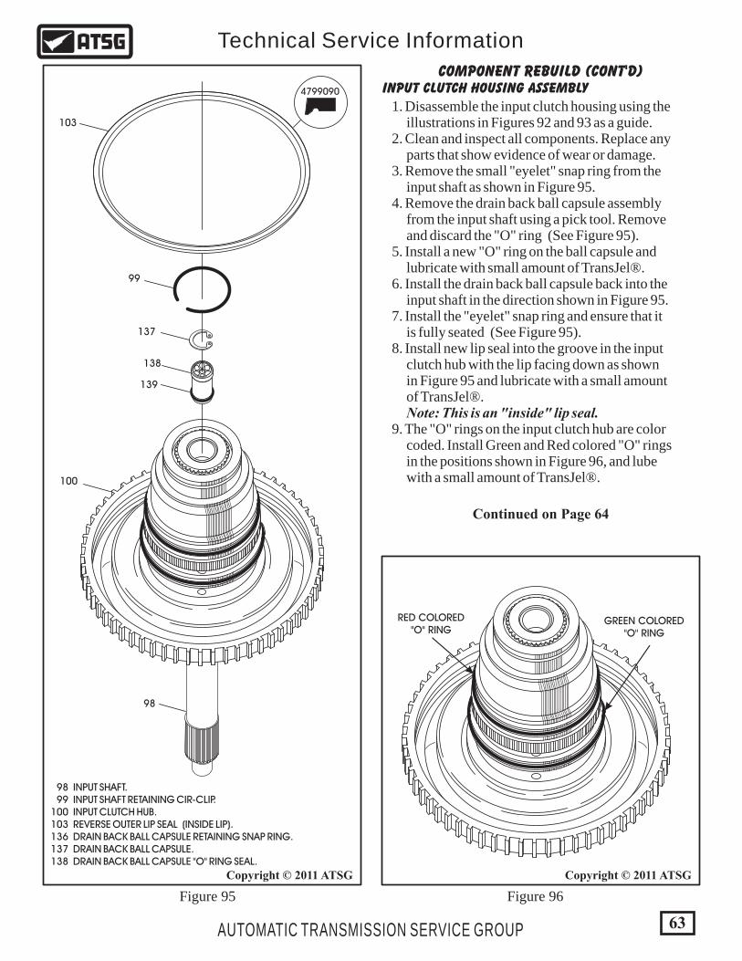
Figure 95 Figure 96
INPUT CLUTCH HOUSING ASSEMBLYCOMPONENT REBUILD (CONT'D)
4799090
100
98
99
139
137
138
103
RED COLORED"O" RING
GREEN COLORED"O" RING
1. Disassemble the input clutch housing using the illustrations in Figures 92 and 93 as a guide. 2. Clean and inspect all components. Replace any parts that show evidence of wear or damage. 3. Remove the small "eyelet" snap ring from the input shaft as shown in Figure 95. 4. Remove the drain back ball capsule assembly from the input shaft using a pick tool. Remove and discard the "O" ring (See Figure 95). 5. Install a new "O" ring on the ball capsule and lubricate with small amount of TransJel®. 6. Install the drain back ball capsule back into the input shaft in the direction shown in Figure 95. 7. Install the "eyelet" snap ring and ensure that it is fully seated (See Figure 95). 8. Install new lip seal into the groove in the input clutch hub with the lip facing down as shown in Figure 95 and lubricate with a small amount of TransJel®. Note: This is an "inside" lip seal. 9. The "O" rings on the input clutch hub are color coded. Install Green and Red colored "O" rings in the positions shown in Figure 96, and lube with a small amount of TransJel®.
Continued on Page 64
98 INPUT SHAFT. 99 INPUT SHAFT RETAINING CIR-CLIP. 100 INPUT CLUTCH HUB. 103 REVERSE OUTER LIP SEAL (INSIDE LIP). 136 DRAIN BACK BALL CAPSULE RETAINING SNAP RING. 137 DRAIN BACK BALL CAPSULE. 138 DRAIN BACK BALL CAPSULE "O" RING SEAL.
63
Copyright © 2011 ATSGCopyright © 2011 ATSG
AUTOMATIC TRANSMISSION SERVICE GROUP
Technical Service Information
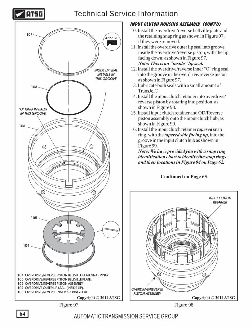
Figure 97 Figure 98
INPUT CLUTCH HOUSING ASSEMBLY (Cont'd)
10. Install the overdrive/reverse bellville plate and the retaining snap ring as shown in Figure 97, if they were removed. 11. Install the overdrive outer lip seal into groove inside the overdrive/reverse piston, with the lip facing down, as shown in Figure 97. Note: This is an "inside" lip seal. 12. Install the overdrive/reverse inner "O" ring seal into the groove in the overdrive/reverse piston as shown in Figure 97. 13. Lubricate both seals with a small amount of TransJel®. 14. Install the input clutch retainer into overdrive/ reverse piston by rotating into position, as shown in Figure 98. 15. Install input clutch retainer and OD/Reverse piston assembly onto the input clutch hub, as shown in Figure 99. 16. Install the input clutch retainer tapered snap ring, with the tapered side facing up, into the groove in the input clutch hub as shown in Figure 99. Note: We have provided you with a snap ring identification chart to identify the snap rings and their locations in Figure 94 on Page 62.
104 OVERDRIVE/REVERSE PISTON BELLVILLE PLATE SNAP RING. 105 OVERDRIVE/REVERSE PISTON BELLVILLE PLATE. 106 OVERDRIVE/REVERSE PISTON ASSEMBLY. 107 OVERDRIVE OUTER LIP SEAL (INSIDE LIP). 108 OVERDRIVE/REVERSE INNER "O" RING SEAL.
4799090
105
104
INPUT CLUTCHRETAINER
OVERDRIVE/REVERSEPISTON ASSEMBLY
107
106
108
"O" RING INSTALLSIN THIS GROOVE
INSIDE LIP SEALINSTALLS IN
THIS GROOVE
64
Copyright © 2011 ATSGCopyright © 2011 ATSG
AUTOMATIC TRANSMISSION SERVICE GROUP
Technical Service Information
Continued on Page 65
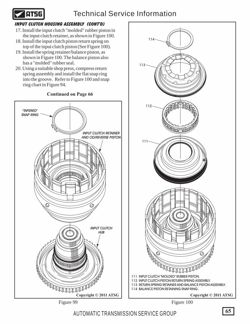
Figure 99 Figure 100
Continued on Page 66
111
112
113
114
"TAPERED"SNAP RING
INPUT CLUTCH RETAINERAND OD/REVERSE PISTON
INPUT CLUTCHHUB
111 INPUT CLUTCH "MOLDED" RUBBER PISTON. 112 INPUT CLUTCH PISTON RETURN SPRING ASSEMBLY. 113 RETURN SPRING RETAINER AND BALANCE PISTON ASSEMBLY. 114 BALANCE PISTON RETAINING SNAP RING.
17. Install the input clutch "molded" rubber piston in the input clutch retainer, as shown in Figure 100. 18. Install the input clutch piston return spring on top of the input clutch piston (See Figure 100). 19. Install the spring retainer/balance piston, as shown in Figure 100. The balance piston also has a "molded" rubber seal. 20. Using a suitable shop press, compress return spring assembly and install the flat snap ring into the groove. Refer to Figure 100 and snap ring chart in Figure 94.
INPUT CLUTCH HOUSING ASSEMBLY (Cont'd)
65
Copyright © 2011 ATSGCopyright © 2011 ATSG
AUTOMATIC TRANSMISSION SERVICE GROUP
Technical Service Information
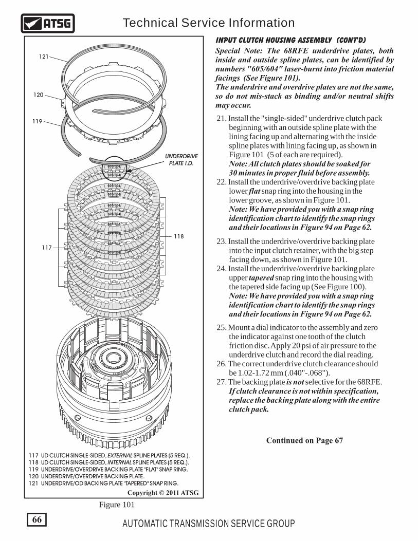
Figure 101
INPUT CLUTCH HOUSING ASSEMBLY (Cont'd)
21. Install the "single-sided" underdrive clutch pack beginning with an outside spline plate with the lining facing up and alternating with the inside spline plates with lining facing up, as shown in Figure 101 (5 of each are required). Note: All clutch plates should be soaked for 30 minutes in proper fluid before assembly. 22. Install the underdrive/overdrive backing plate lower flat snap ring into the housing in the lower groove, as shown in Figure 101. Note: We have provided you with a snap ring identification chart to identify the snap rings and their locations in Figure 94 on Page 62.
119
120
121Special Note: The 68RFE underdrive plates, both inside and outside spline plates, can be identified by numbers "605/604" laser-burnt into friction material facings (See Figure 101).The underdrive and overdrive plates are not the same, so do not mis-stack as binding and/or neutral shifts may occur.
23. Install the underdrive/overdrive backing plate into the input clutch retainer, with the big step facing down, as shown in Figure 101. 24. Install the underdrive/overdrive backing plate upper tapered snap ring into the housing with the tapered side facing up (See Figure 100). Note: We have provided you with a snap ring identification chart to identify the snap rings and their locations in Figure 94 on Page 62.
25. Mount a dial indicator to the assembly and zero the indicator against one tooth of the clutch friction disc. Apply 20 psi of air pressure to the underdrive clutch and record the dial reading. 26. The correct underdrive clutch clearance should be 1.02-1.72 mm (.040"-.068"). 27. The backing plate is not selective for the 68RFE. If clutch clearance is not within specification, replace the backing plate along with the entire clutch pack.
117
118
UNDERDRIVEPLATE I.D.
117 UD CLUTCH SINGLE-SIDED, EXTERNAL SPLINE PLATES (5 REQ.). 118 UD CLUTCH SINGLE-SIDED, INTERNAL SPLINE PLATES (5 REQ.). 119 UNDERDRIVE/OVERDRIVE BACKING PLATE "FLAT" SNAP RING. 120 UNDERDRIVE/OVERDRIVE BACKING PLATE. 121 UNDERDRIVE/OD BACKING PLATE "TAPERED" SNAP RING.
45 0/660
45 0/660
45 0/660
45 0/660
45 0/660
45 0/660
45 0/660
45 0/660
45 0/660
45 0/660
Continued on Page 67
66
Copyright © 2011 ATSG
AUTOMATIC TRANSMISSION SERVICE GROUP
Technical Service Information
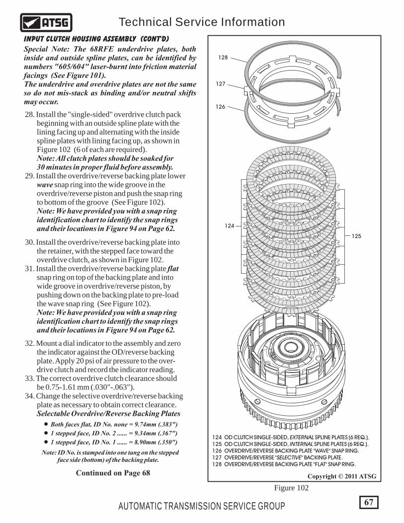
Figure 102
Continued on Page 68
126
127
128
30. Install the overdrive/reverse backing plate into the retainer, with the stepped face toward the overdrive clutch, as shown in Figure 102. 31. Install the overdrive/reverse backing plate flat snap ring on top of the backing plate and into wide groove in overdrive/reverse piston, by pushing down on the backing plate to pre-load the wave snap ring (See Figure 102). Note: We have provided you with a snap ring identification chart to identify the snap rings and their locations in Figure 94 on Page 62.
32. Mount a dial indicator to the assembly and zero the indicator against the OD/reverse backing plate. Apply 20 psi of air pressure to the over- drive clutch and record the indicator reading. 33. The correct overdrive clutch clearance should be 0.75-1.61 mm (.030"-.063"). 34. Change the selective overdrive/reverse backing plate as necessary to obtain correct clearance. Selectable Overdrive/Reverse Backing Plates
124
125
124 OD CLUTCH SINGLE-SIDED, EXTERNAL SPLINE PLATES (6 REQ.). 125 OD CLUTCH SINGLE-SIDED, INTERNAL SPLINE PLATES (6 REQ.). 126 OVERDRIVE/REVERSE BACKING PLATE "WAVE" SNAP RING. 127 OVERDRIVE/REVERSE "SELECTIVE" BACKING PLATE. 128 OVERDRIVE/REVERSE BACKING PLATE "FLAT" SNAP RING.
INPUT CLUTCH HOUSING ASSEMBLY (Cont'd)
28. Install the "single-sided" overdrive clutch pack beginning with an outside spline plate with the lining facing up and alternating with the inside spline plates with lining facing up, as shown in Figure 102 (6 of each are required). Note: All clutch plates should be soaked for 30 minutes in proper fluid before assembly. 29. Install the overdrive/reverse backing plate lower wave snap ring into the wide groove in the overdrive/reverse piston and push the snap ring to bottom of the groove (See Figure 102). Note: We have provided you with a snap ring identification chart to identify the snap rings and their locations in Figure 94 on Page 62.
Both faces flat, ID No. none = 9.74mm (.383")
1 stepped face, ID No. 2 ...... = 9.34mm (.367")
1 stepped face, ID No. 1 ...... = 8.90mm (.350")
67
Copyright © 2011 ATSG
AUTOMATIC TRANSMISSION SERVICE GROUP
Technical Service Information
Special Note: The 68RFE underdrive plates, both inside and outside spline plates, can be identified by numbers "605/604" laser-burnt into friction material facings (See Figure 101).The underdrive and overdrive plates are not the same so do not mis-stack as binding and/or neutral shifts may occur.
Note: ID No. is stamped into one tang on the stepped face side (bottom) of the backing plate.
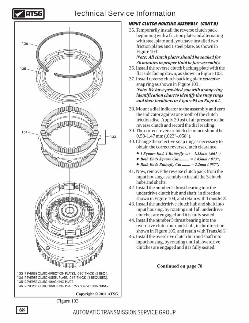
Figure 103
INPUT CLUTCH HOUSING ASSEMBLY (Cont'd)
35. Temporarily install the reverse clutch pack beginning with a friction plate and alternating with steel plate until you have installed two friction plates and 1 steel plate, as shown in Figure 103. Note: All clutch plates should be soaked for 30 minutes in proper fluid before assembly. 36. Install the reverse clutch backing plate with the flat side facing down, as shown in Figure 103. 37. Install reverse clutch backing plate selective snap ring as shown in Figure 103. Note: We have provided you with a snap ring identification chart to identify the snap rings and their locations in Figure94 on Page 62.
134
133
136
135
38. Mount a dial indicator to the assembly and zero the indicator against one tooth of the clutch friction disc. Apply 20 psi of air pressure to the reverse clutch and record the dial reading. 39. The correct reverse clutch clearance should be 0.58-1.47 mm (.023"-.058"). 40. Change the selective snap ring as necessary to obtain the correct reverse clutch clearance.
41. Now, remove the reverse clutch pack from the input housing assembly to install the 3 clutch hubs and shafts. 42. Install the number 2 thrust bearing into the underdrive clutch hub and shaft, in direction shown in Figure 104, and retain with TransJel®. 43. Install the underdrive clutch hub and shaft into input housing, by rotating until all underdrive clutches are engaged and it is fully seated. 44. Install the number 3 thrust bearing into the overdrive clutch hub and shaft, in the direction shown in Figure 105, and retain with TransJel®. 45. Install the overdrive clutch hub and shaft into input housing, by rotating until all overdrive clutches are engaged and it is fully seated.
Continued on page 70
133 REVERSE CLUTCH FRICTION PLATES, .080" THICK (2 REQ.). 134 REVERSE CLUTCH STEEL PLATE, .067" THICK (1 REQUIRED). 135 REVERSE CLUTCH BACKING PLATE. 136 REVERSE CLUTCH BACKING PLATE "SELECTIVE" SNAP RING.
1 Square End, 1 Butterfly cut = 1.55mm (.061")
Both Ends Square Cut .......... = 1.85mm (.073")
Both Ends Butterfly Cut ........ = 2.2mm (.087")
68
Copyright © 2011 ATSG
AUTOMATIC TRANSMISSION SERVICE GROUP
Technical Service Information
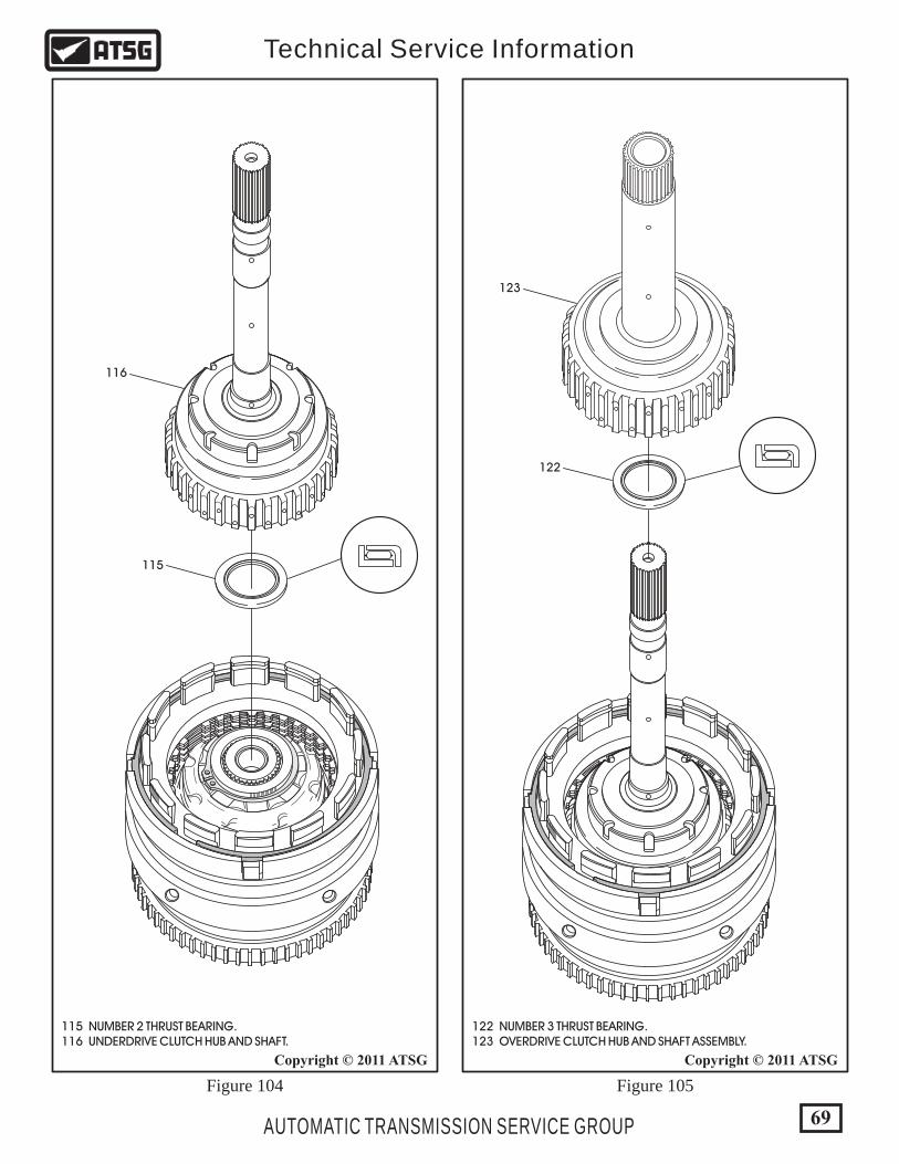
Figure 104 Figure 105
115
122
116
123
122 NUMBER 3 THRUST BEARING. 123 OVERDRIVE CLUTCH HUB AND SHAFT ASSEMBLY.
115 NUMBER 2 THRUST BEARING. 116 UNDERDRIVE CLUTCH HUB AND SHAFT.
69
Copyright © 2011 ATSGCopyright © 2011 ATSG
AUTOMATIC TRANSMISSION SERVICE GROUP
Technical Service Information
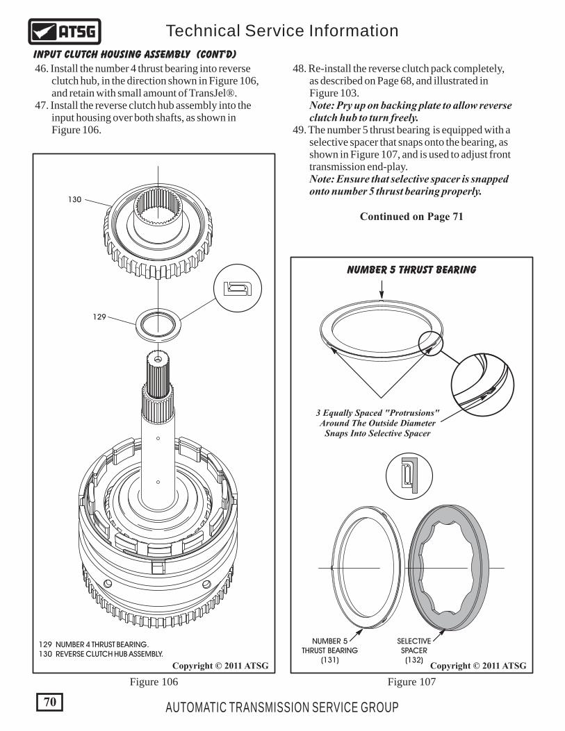
Figure 106 Figure 107
48. Re-install the reverse clutch pack completely, as described on Page 68, and illustrated in Figure 103. Note: Pry up on backing plate to allow reverse clutch hub to turn freely. 49. The number 5 thrust bearing is equipped with a selective spacer that snaps onto the bearing, as shown in Figure 107, and is used to adjust front transmission end-play. Note: Ensure that selective spacer is snapped onto number 5 thrust bearing properly.
46. Install the number 4 thrust bearing into reverse clutch hub, in the direction shown in Figure 106, and retain with small amount of TransJel®. 47. Install the reverse clutch hub assembly into the input housing over both shafts, as shown in Figure 106.
129
NUMBER 5THRUST BEARING
(131)
SELECTIVESPACER(132)
130
129 NUMBER 4 THRUST BEARING. 130 REVERSE CLUTCH HUB ASSEMBLY.
3 Equally Spaced "Protrusions"Around The Outside Diameter
Snaps Into Selective Spacer
NUMBER 5 THRUST BEARING
Continued on Page 71
INPUT CLUTCH HOUSING ASSEMBLY (Cont'd)
70
Copyright © 2011 ATSGCopyright © 2011 ATSG
AUTOMATIC TRANSMISSION SERVICE GROUP
Technical Service Information

Figure 108 Figure 109
131
96
131 NUMBER 5 THRUST BEARING AND "SELECTIVE" SPACER. 96 INPUT SHAFT SEAL RINGS (2 REQUIRED).
50. Install the number 5 thrust bearing and selective spacer on the back side of reverse clutch hub, as shown in Figure 108 and retain with TransJel®. 51. Install two new input shaft seals into the grooves on input shaft, as shown in Figure 109, ensure they are properly seated and rotate freely. 52. Set the completed input housing assembly aside for the final assembly process.
INPUT CLUTCH HOUSING ASSEMBLY (Cont'd)
71
Copyright © 2011 ATSG Copyright © 2011 ATSG
AUTOMATIC TRANSMISSION SERVICE GROUP
Technical Service Information
Component RebuildContinued on Page 72

60 OIL PUMP BODY. 61 OIL PUMP BODY TO PUMP COVER BOLTS (24 REQUIRED). 62 PUMP BODY TO PUMP COVER "HOLLOW" DOWELS (2 REQ.). 63 OIL PUMP SHUTTLE VALVE. 64 OIL PUMP DRIVE GEAR. 65 OIL PUMP DRIVEN GEARS. 66 OIL PUMP BODY TO PUMP COVER SPACER PLATE. 67 OIL PUMP SPACER PLATE RETAINING SCREWS (2 REQUIRED). 68 OIL PUMP COVER ASSEMBLY. 69 OIL PUMP STATOR SHAFT ASSEMBLY. 70 OIL PUMP STATOR SHAFT STEEL SEALING RINGS (5 REQUIRED). 71 PUMP STATOR TO PUMP BODY RETAINING BOLTS (5 REQUIRED). 87 MAIN FILTER SEAL.
Figure 110
70
71
69
65
66
6767
87
68
60
61
61
62 63
64
62
210
OIL PUMP ASSEMBLY EXPLODED VIEW
72
Copyright © 2011 ATSG
AUTOMATIC TRANSMISSION SERVICE GROUP
Technical Service Information
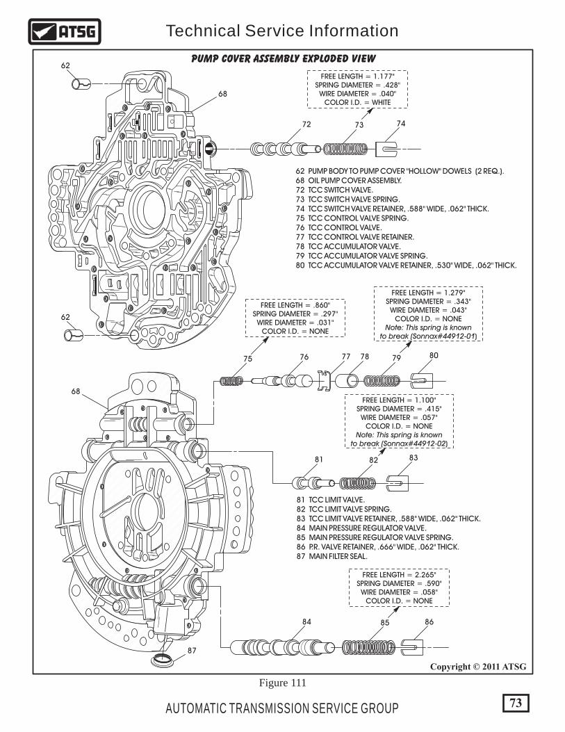
62 PUMP BODY TO PUMP COVER "HOLLOW" DOWELS (2 REQ.). 68 OIL PUMP COVER ASSEMBLY. 72 TCC SWITCH VALVE. 73 TCC SWITCH VALVE SPRING. 74 TCC SWITCH VALVE RETAINER, .588" WIDE, .062" THICK. 75 TCC CONTROL VALVE SPRING. 76 TCC CONTROL VALVE. 77 TCC CONTROL VALVE RETAINER. 78 TCC ACCUMULATOR VALVE. 79 TCC ACCUMULATOR VALVE SPRING. 80 TCC ACCUMULATOR VALVE RETAINER, .530" WIDE, .062" THICK.
81 TCC LIMIT VALVE. 82 TCC LIMIT VALVE SPRING. 83 TCC LIMIT VALVE RETAINER, .588" WIDE, .062" THICK. 84 MAIN PRESSURE REGULATOR VALVE. 85 MAIN PRESSURE REGULATOR VALVE SPRING. 86 P.R. VALVE RETAINER, .666" WIDE, .062" THICK. 87 MAIN FILTER SEAL.
68
68
62
62
72 73 74
75 76 77 78 79 80
81 82 83
84 85 86
87
PUMP COVER ASSEMBLY EXPLODED VIEW
FREE LENGTH = 1.177"SPRING DIAMETER = .428"WIRE DIAMETER = .040"
COLOR I.D. = WHITE
FREE LENGTH = .860"SPRING DIAMETER = .297"WIRE DIAMETER = .031"
COLOR I.D. = NONE
FREE LENGTH = 1.279"SPRING DIAMETER = .343"WIRE DIAMETER = .043"
COLOR I.D. = NONENote: This spring is known
to break (Sonnax#44912-01)
FREE LENGTH = 1.100"SPRING DIAMETER = .415"WIRE DIAMETER = .057"
COLOR I.D. = NONENote: This spring is known
to break (Sonnax#44912-02)
FREE LENGTH = 2.265"SPRING DIAMETER = .590"WIRE DIAMETER = .058"
COLOR I.D. = NONE
Figure 111
73
Copyright © 2011 ATSG
AUTOMATIC TRANSMISSION SERVICE GROUP
Technical Service Information
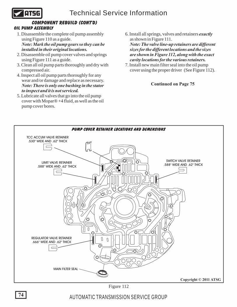
SWITCH VALVE RETAINER.588" WIDE AND .62" THICK
LIMIT VALVE RETAINER.588" WIDE AND .62" THICK
REGULATOR VALVE RETAINER.666" WIDE AND .62" THICK
MAIN FILTER SEAL
TCC ACCUM VALVE RETAINER.530" WIDE AND .62" THICK
PUMP COVER RETAINER LOCATIONS AND DEMENSIONS
Figure 112
74
Copyright © 2011 ATSG
AUTOMATIC TRANSMISSION SERVICE GROUP
Technical Service Information
COMPONENT REBUILD (CONT'D)OIL PUMP ASSEMBLY
1. Disassemble the complete oil pump assembly using Figure 110 as a guide. Note: Mark the oil pump gears so they can be installed in their original locations. 2. Disassemble oil pump cover valves and springs using Figure 111 as a guide. 3. Clean all oil pump parts thoroughly and dry with compressed air. 4. Inspect all oil pump parts thoroughly for any wear and/or damage and replace as necessary. Note: There is only one bushing in the stator to inspect and it is not serviced. 5. Lubricate all valves that go into the oil pump cover with Mopar® +4 fluid, as well as the oil pump cover bores.
6. Install all springs, valves and retainers exactly as shown in Figure 111. Note: The valve line-up retainers are different sizes for the different locations and the sizes are shown in Figure 112, along with the exact cavity locations for the various retainers. 7. Install new main filter seal into the oil pump cover using the proper driver (See Figure 112).
Continued on Page 75

23
67
"Do Not" Leave TheSpacer Plate Screws Out
60 OIL PUMP BODY. 62 PUMP BODY TO PUMP COVER "HOLLOW" DOWELS (2 REQ.). 63 OIL PUMP SHUTTLE VALVE. 64 OIL PUMP DRIVE GEAR. 65 OIL PUMP DRIVEN GEARS.
63 OIL PUMP SHUTTLE VALVE. 66 OIL PUMP BODY TO PUMP COVER SPACER PLATE. 67 OIL PUMP SPACER PLATE RETAINING SCREWS (2 REQUIRED).
60
66
636262
63
64
65
65
Figure 113 Figure 114
75
Copyright © 2011 ATSGCopyright © 2011 ATSG
AUTOMATIC TRANSMISSION SERVICE GROUP
Technical Service Information
COMPONENT REBUILD (CONT'D)OIL PUMP ASSEMBLY (CONT'D)
8. Install the alignment dowels into oil pump body, if they were removed, as shown in Figure 113. 9. Dip all 3 of the pump gears into Mopar® +4 fluid and install them in their original locations, shown in Figure 113. 10. Install the shuttle valve into the oil pump body in the location shown in Figure 113. 11. Ensure the shuttle valve is seated and install the oil pump spacer plate over the alignment dowels, as shown in Figure 114. 12. Install the two spacer plate retaining screws, as shown in Figure 114, and torque the screws to 4.5N·m (40 in.lb.). Note: Leaving these two screws out will create a "No Engagement" condition.
Continued on Page 76

210
Figure 115
Figure 116
23
COMPLETEDOIL PUMPCOVER
COMPLETEDOIL PUMP
BODY
OIL PUMP BODYTO PUMP COVER SCREWS
(24 REQUIRED)
69
71
71
23
69 OIL PUMP STATOR SHAFT ASSEMBLY. 71 PUMP STATOR TO PUMP BODY RETAINING BOLTS (5 REQUIRED).
Figure 117
OIL PUMP ASSEMBLY (CONT'D)
Continued on Page 77
13. Install completed oil pump cover onto completed oil pump body and over the alignment dowels, as shown in Figure 115. 14. Seat the two halves together and very carefully turn the assembly over, as shown in Figure 116, and start all 24 screws finger tight. 15. Torque the pump screws to 4.5 N·m (40 in.lb.), starting in the center and working outward in a circle. 16. Install the stator shaft support into the oil pump assembly resting on blocks, as shown in Figure 117. 17. Install the five stator support bolts, as shown in Figure 117, and torque to 12 N·m (105 in.lb.).
76
Copyright © 2011 ATSGCopyright © 2011 ATSG
Copyright © 2011 ATSG
AUTOMATIC TRANSMISSION SERVICE GROUP
Technical Service Information

18. Install five new sealing rings on stator support in their respective grooves and ensure that they are properly hooked (See Figure 118). 19. Set the completed oil pump assembly, as shown in Figure 119, aside for final assembly. Note: Notice that oil pump body has no pocket for the converter hub seal. The converter hub seal is now located in the front cover.
23
70 OIL PUMP STATOR SHAFT STEEL SEALING RINGS (5 REQUIRED).
70
COMPLETED OIL PUMP ASSEMBLY
210
77
Copyright © 2011 ATSG
Copyright © 2011 ATSG
AUTOMATIC TRANSMISSION SERVICE GROUP
Technical Service Information
OIL PUMP ASSEMBLY (CONT'D)
Component RebuildContinued on Page 78
Figure 118
Figure 119
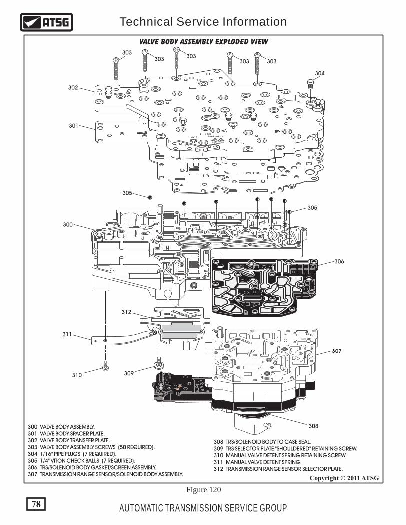
VALVE BODY ASSEMBLY EXPLODED VIEW
Figure 120
479965505111
AK 1
98
302
303303
303 303303
304
301
305
305
306
307
308
309310
311
312
300
300 VALVE BODY ASSEMBLY. 301 VALVE BODY SPACER PLATE. 302 VALVE BODY TRANSFER PLATE. 303 VALVE BODY ASSEMBLY SCREWS (50 REQUIRED). 304 1/16" PIPE PLUGS (7 REQUIRED). 305 1/4" VITON CHECK BALLS (7 REQUIRED). 306 TRS/SOLENOID BODY GASKET/SCREEN ASSEMBLY. 307 TRANSMISSION RANGE SENSOR/SOLENOID BODY ASSEMBLY.
308 TRS/SOLENOID BODY TO CASE SEAL. 309 TRS SELECTOR PLATE "SHOULDERED" RETAINING SCREW. 310 MANUAL VALVE DETENT SPRING RETAINING SCREW. 311 MANUAL VALVE DETENT SPRING. 312 TRANSMISSION RANGE SENSOR SELECTOR PLATE.
10300023
1527
31657
13
1498
LOT 5LOT 5
78
Copyright © 2011 ATSG
AUTOMATIC TRANSMISSION SERVICE GROUP
Technical Service Information

1527
31657
13
1498
LOT 5LOT 5
10300023
479965505111
AK 1
98
Figure 122
Figure 121
COMPLETE VALVE BODY ASSEMBLY
VALVE BODY DISASSEMBLY
REMOVE THE 15 SCREWS THATARE SHADED TO REMOVE THE
TRANSMISSION RANGE SENSOR
"DO NOT" REMOVE THESE SEVEN SCREWSFROM TOP OF TRANSMISSION RANGE SENSOR
"DO NOT" CLEAN WITH SOLVENT
TRS/SOLENOID BODYASSEMBLY
1. Remove the 15 screws that are shaded as shown in Figure 122. These screws must be removed first, so the TRS/Solenoid Body that contains most of the electrical components, will not be cleaned with any solvents. 2. Do Not remove the seven screws from the top of the TRS/Solenoid Body (See Figure 121). Note: There is nothing on the inside of the TRS/Solenoid Pack that is serviced. It must be replaced as an assembly. 3. Once the TRS/Solenoid Body is seperated from the valve body assembly, continue disassembly of the valve body using Figure 120 as a guide. 4. Notice in Figure 120 that valve body contains seven checkballs. Care should be taken to keep the valve body in the position shown, when you are removing the transfer plate, so as not to lose any of the checkballs.
79
Copyright © 2011 ATSG
Copyright © 2011 ATSG
AUTOMATIC TRANSMISSION SERVICE GROUP
Technical Service Information
Continued on Page 81
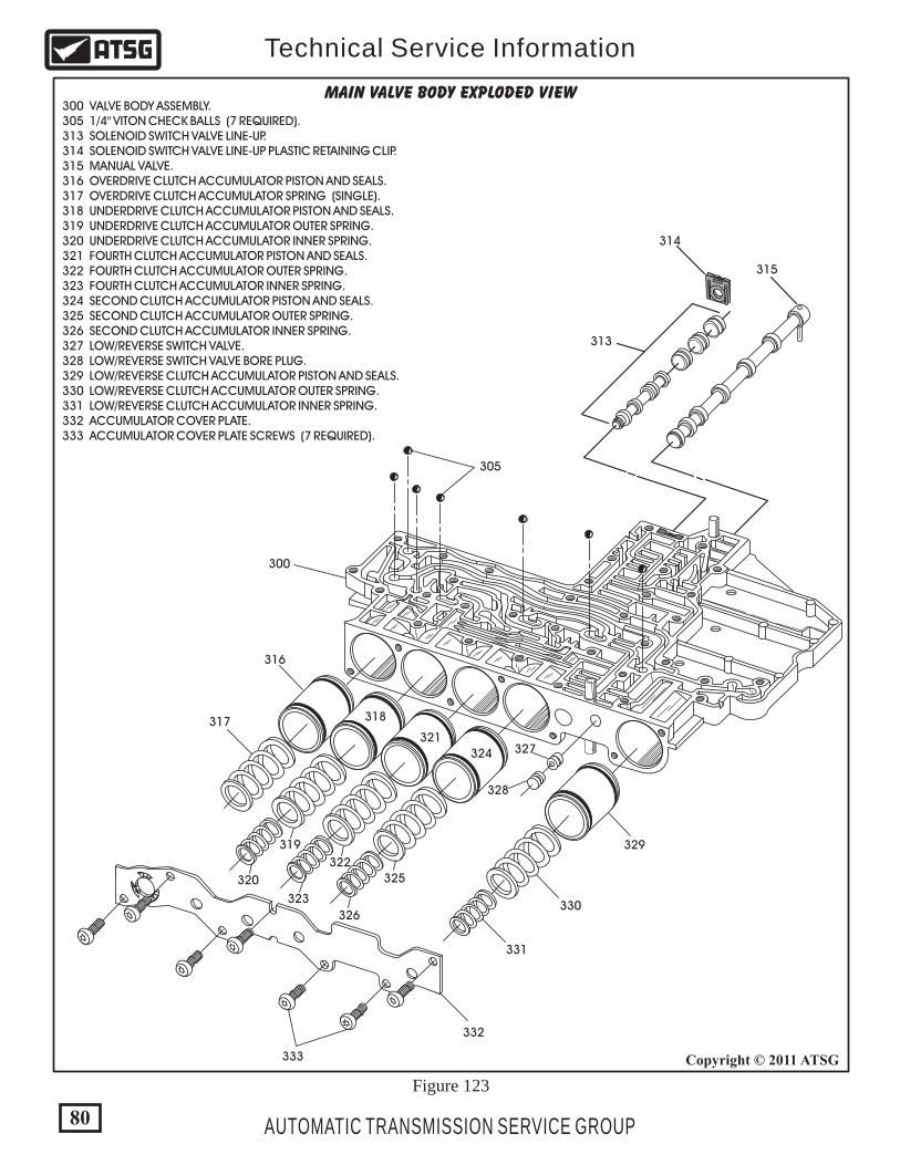
300 VALVE BODY ASSEMBLY. 305 1/4" VITON CHECK BALLS (7 REQUIRED). 313 SOLENOID SWITCH VALVE LINE-UP. 314 SOLENOID SWITCH VALVE LINE-UP PLASTIC RETAINING CLIP. 315 MANUAL VALVE. 316 OVERDRIVE CLUTCH ACCUMULATOR PISTON AND SEALS. 317 OVERDRIVE CLUTCH ACCUMULATOR SPRING (SINGLE). 318 UNDERDRIVE CLUTCH ACCUMULATOR PISTON AND SEALS. 319 UNDERDRIVE CLUTCH ACCUMULATOR OUTER SPRING. 320 UNDERDRIVE CLUTCH ACCUMULATOR INNER SPRING. 321 FOURTH CLUTCH ACCUMULATOR PISTON AND SEALS. 322 FOURTH CLUTCH ACCUMULATOR OUTER SPRING. 323 FOURTH CLUTCH ACCUMULATOR INNER SPRING. 324 SECOND CLUTCH ACCUMULATOR PISTON AND SEALS. 325 SECOND CLUTCH ACCUMULATOR OUTER SPRING. 326 SECOND CLUTCH ACCUMULATOR INNER SPRING. 327 LOW/REVERSE SWITCH VALVE. 328 LOW/REVERSE SWITCH VALVE BORE PLUG. 329 LOW/REVERSE CLUTCH ACCUMULATOR PISTON AND SEALS. 330 LOW/REVERSE CLUTCH ACCUMULATOR OUTER SPRING. 331 LOW/REVERSE CLUTCH ACCUMULATOR INNER SPRING. 332 ACCUMULATOR COVER PLATE. 333 ACCUMULATOR COVER PLATE SCREWS (7 REQUIRED).
Figure 123
MAIN VALVE BODY EXPLODED VIEW
300
316
317
321
318
324
319
320
327
322
323
328
330
331
332
333
325
326
329
305
313
314
315
80
Copyright © 2011 ATSG
AUTOMATIC TRANSMISSION SERVICE GROUP
Technical Service Information
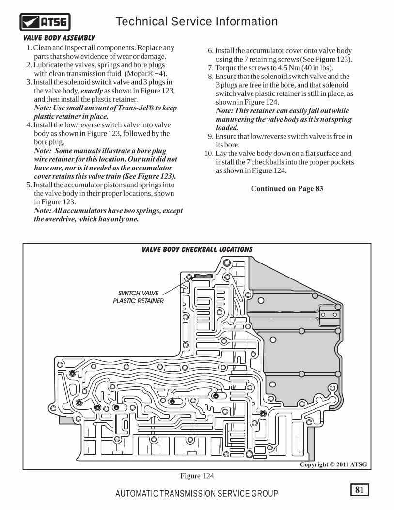
Figure 124
VALVE BODY CHECKBALL LOCATIONS
VALVE BODY ASSEMBLY
1. Clean and inspect all components. Replace any parts that show evidence of wear or damage. 2. Lubricate the valves, springs and bore plugs with clean transmission fluid (Mopar® +4). 3. Install the solenoid switch valve and 3 plugs in the valve body, exactly as shown in Figure 123, and then install the plastic retainer. Note: Use small amount of Trans-Jel® to keep plastic retainer in place. 4. Install the low/reverse switch valve into valve body as shown in Figure 123, followed by the bore plug. Note: Some manuals illustrate a bore plug wire retainer for this location. Our unit did not have one, nor is it needed as the accumulator cover retains this valve train (See Figure 123). 5. Install the accumulator pistons and springs into the valve body in their proper locations, shown in Figure 123. Note: All accumulators have two springs, except the overdrive, which has only one.
6. Install the accumulator cover onto valve body using the 7 retaining screws (See Figure 123). 7. Torque the screws to 4.5 Nm (40 in lbs). 8. Ensure that the solenoid switch valve and the 3 plugs are free in the bore, and that solenoid switch valve plastic retainer is still in place, as shown in Figure 124. Note: This retainer can easily fall out while manuvering the valve body as it is not spring loaded. 9. Ensure that low/reverse switch valve is free in its bore. 10. Lay the valve body down on a flat surface and install the 7 checkballs into the proper pockets as shown in Figure 124.
Continued on Page 83
SWITCH VALVEPLASTIC RETAINER
81
Copyright © 2011 ATSG
AUTOMATIC TRANSMISSION SERVICE GROUP
Technical Service Information
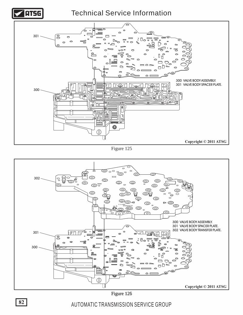
Figure 125Figure 126
Figure 125
479965505111
AK 1
98
82
Copyright © 2011 ATSG
Copyright © 2011 ATSG
AUTOMATIC TRANSMISSION SERVICE GROUP
Technical Service Information
300 VALVE BODY ASSEMBLY. 301 VALVE BODY SPACER PLATE. 302 VALVE BODY TRANSFER PLATE.
300 VALVE BODY ASSEMBLY. 301 VALVE BODY SPACER PLATE.
300
300
301
302
301

Figure 127
TRANSFER PLATE TO VALVE BODY BOLT LOCATIONS
TRANSFER PLATE TO VALVE BODYRETAINING SCREWS (303) (35 REQUIRED HERE)
479965505111
AK 1
98
VALVE BODY ASSEMBLY (CONT'D)
Continued on Page 84
11. Install the valve body spacer plate over the locating dowels and onto the valve body as shown in Figure 125. 12. Install the transfer plate over locating dowels and onto the valve body as shown in Figure 126. 13. Install the 35 valve body to transfer plate bolts in the locations shown in Figure 127. 14. Torque the valve body to transfer plate bolts to 4.5 Nm (40 in lbs). Note: Turn the assembly over to continue the assembly process.
83
Copyright © 2011 ATSG
AUTOMATIC TRANSMISSION SERVICE GROUP
Technical Service Information
300 VALVE BODY ASSEMBLY. 301 VALVE BODY SPACER PLATE. 302 VALVE BODY TRANSFER PLATE. 303 VALVE BODY ASSEMBLY SCREWS (50 REQUIRED).
300
301
302
303

4799591
97
15. Install the manual valve into the manual valve bore in the valve body with the stem facing up and engaged in the groove (See Figure 128). 16. Install the transmission range sensor selector plate into the groove in the valve body and over the stem on the manual valve (See Figure 128). Note: The Transmission Range Selector Plate will not interchange with the 45RFE plate, as shown in Figure 129. 17. Install the shouldered retaining bolt for the transmission range sensor selector plate and torque the bolt to 4.5 Nm (40 in lbs). Refer to Figure 128. 18. Install the manual valve detent spring and bolt and torque bolt to 4.5 Nm (40 in lbs). Refer to Figure 128.
19. Install a new low/reverse seal into the valve body with the "house-top" facing up, as shown in Figure 130. 20. Install a new 2nd clutch seal into the valve body with the "house-top" facing up, as shown in Figure 130. 21. Install a new 4th clutch seal into the valve body with the "house-top" facing up, as shown in Figure 130.
Figure 128
TRANSMISSION RANGE SENSORSELECTOR PLATE
MANUALVALVEDETENT SPRING
SHOULDEREDBOLT
VALVE BODY ASSEMBLY (CONT'D)
Continued on Page 86
84
Copyright © 2011 ATSG
AUTOMATIC TRANSMISSION SERVICE GROUP
Technical Service Information

TRANSMISSION RANGE SENSOR SELECTOR PLATE68RFE
POCKET FORPIN T41 IS .156" DEEP
45RFEPOCKET FOR
PIN T41 IS .118" DEEP
4799591
97
4th ClutchSeal
2nd ClutchSeal
L/R ClutchSeal
These Selector Plates"Will Not" Interchange
Figure 130
Figure 129
ALL 3SEALS
85
Copyright © 2011 ATSG
Copyright © 2011 ATSG
AUTOMATIC TRANSMISSION SERVICE GROUP
Technical Service Information
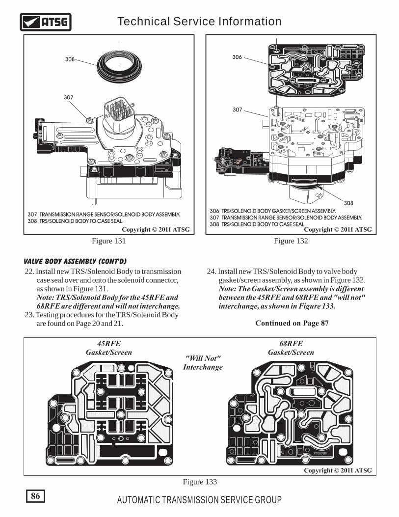
Figure 132
Figure 133
10300023
1527
31657
13
1498
LOT 5LOT 5
306 TRS/SOLENOID BODY GASKET/SCREEN ASSEMBLY. 307 TRANSMISSION RANGE SENSOR/SOLENOID BODY ASSEMBLY. 308 TRS/SOLENOID BODY TO CASE SEAL.
308
307
306
Figure 131
22. Install new TRS/Solenoid Body to transmission case seal over and onto the solenoid connector, as shown in Figure 131. Note: TRS/Solenoid Body for the 45RFE and 68RFE are different and will not interchange. 23. Testing procedures for the TRS/Solenoid Body are found on Page 20 and 21.
24. Install new TRS/Solenoid Body to valve body gasket/screen assembly, as shown in Figure 132. Note: The Gasket/Screen assembly is different between the 45RFE and 68RFE and "will not" interchange, as shown in Figure 133.
VALVE BODY ASSEMBLY (CONT'D)
Continued on Page 87
307 TRANSMISSION RANGE SENSOR/SOLENOID BODY ASSEMBLY. 308 TRS/SOLENOID BODY TO CASE SEAL.
308
307
10300023
45RFEGasket/Screen
68RFEGasket/Screen
"Will Not"Interchange
86
Copyright © 2011 ATSG
Copyright © 2011 ATSGCopyright © 2011 ATSG
AUTOMATIC TRANSMISSION SERVICE GROUP
Technical Service Information

1527
31657
13
1498
LOT 5LOT 5
10300023
479965505111
AK 1
98
INSTALL ONE SCREW ANDHAND TIGHTEN ONLY
Figure 134
25. Install the TRS/Solenoid Pack assembly to the transfer plate, as shown in Figure 134. Note: Use caution installing the TRS/Solenoid Pack as the assembly has locating dowels that must line up with bores in the transfer plate. 26. Install one screw and hand tighten only, as shown in Figure 134.
87
Copyright © 2011 ATSG
AUTOMATIC TRANSMISSION SERVICE GROUP
Technical Service Information
VALVE BODY ASSEMBLY (CONT'D)
Continued on Page 88
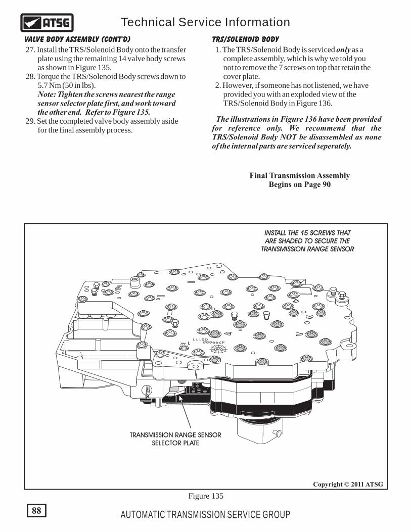
1527
31657
13
1498
LOT 5LOT 5
10300023
479965505111
AK 1
98
INSTALL THE 15 SCREWS THATARE SHADED TO SECURE THE
TRANSMISSION RANGE SENSOR
TRANSMISSION RANGE SENSORSELECTOR PLATE
27. Install the TRS/Solenoid Body onto the transfer plate using the remaining 14 valve body screws as shown in Figure 135. 28. Torque the TRS/Solenoid Body screws down to 5.7 Nm (50 in lbs). Note: Tighten the screws nearest the range sensor selector plate first, and work toward the other end. Refer to Figure 135. 29. Set the completed valve body assembly aside for the final assembly process.
VALVE BODY ASSEMBLY (CONT'D) TRS/SOLENOID BODY
Final Transmission AssemblyBegins on Page 90
Figure 135
88
Copyright © 2011 ATSG
AUTOMATIC TRANSMISSION SERVICE GROUP
Technical Service Information
1. The TRS/Solenoid Body is serviced only as a complete assembly, which is why we told you not to remove the 7 screws on top that retain the cover plate. 2. However, if someone has not listened, we have provided you with an exploded view of the TRS/Solenoid Body in Figure 136.
The illustrations in Figure 136 have been provided for reference only. We recommend that the TRS/Solenoid Body NOT be disassembled as none of the internal parts are serviced seperately.

TRANSMISSION RANGE SENSOR/SOLENOID BODY, EXPLODED VIEW
1
2
22
3
4
5
6
78
1. TRS/SOLENOID BODY COVER RETAINING SCREWS (6 LONG REQ). 2. TRS/SOLENOID BODY COVER RETAINING SCREW (1 SHORT REQ). 3. TRS/SOLENOID BODY COVER. 4. HYDRAULIC SWITCH RETURN SPRINGS (5 REQUIRED). 5. TRS/SOLENOID BODY AND 23 WAY CONNECTOR. 6. HYDRAULIC SWITCH COPPER CONTACT (5 REQUIRED). 7. HYDRAULIC SWITCH LIP SEAL (5 REQUIRED). 8. HYDRAULIC SWITCH COVER (5 REQUIRED). 9. SOLENOID DAMPENER (6 REQUIRED). 10. SOLENOID BODY. 11. LOW/REVERSE CLUTCH SOLENOID (NORMALLY VENTED). 12. MULTI-SELECT SOLENOID (NORMALLY APPLIED). 13. UNDERDRIVE CLUTCH SOLENOID (NORMALLY APPLIED). 14. OVERDRIVE CLUTCH SOLENOID (NORMALLY VENTED). 15. FOURTH CLUTCH SOLENOID (NORMALLY VENTED). 16. SECOND CLUTCH SOLENOID (NORMALLY VENTED). 17. LINE PRESSURE SOLENOID SMALL "O" RING. 18. LINE PRESSURE SOLENOID LARGE “O” RING. 19. LINE PRESSURE SOLENOID WAVE WASHER. 20. LINE PRESSURE SOLENOID (NORMALLY VENTED). 21. LINE PRESSURE SOLENOID RETAINING PINS (2 REQUIRED). 22. TRS/SOLENOID BODY TO CASE SEAL. 23. TRS/SOLENOID BODY GASKET/SCREEN ASSEMBLY.
Figure 136
9
10
11
12
13
14
15
16
17 18 1920
21
23
This Illustration Is For"Reference Only"
There Is "Nothing" ServicedSeperately Except The Case SealAnd The Gasket/Screen Assembly
89
Copyright © 2011 ATSG
AUTOMATIC TRANSMISSION SERVICE GROUP
Technical Service Information

Figure 138Figure 137
Before final assembly of transmission, the second clutch pack complete and 2-4 retainer must be temporarily installed in the transmission case to measure for proper second clutch clearance.
Continued on Page 91
TRANSMISSION ASSEMBLY
Copyright © 2011 ATSG
151 SECOND CLUTCH STEEL PLATES (.130" THICK) (3 REQUIRED). 152 SECOND CLUTCH FRICTION PLATES (.090" THICK) (3 REQ). 153 SECOND CLUTCH BACKING PLATE (.325" THICK).
153
152
151
140 2-4 CLUTCH RETAINER ASSEMBLY. 154 2-4 RETAINER TO CASE "TAPERED" SNAP RING. 155 2-4 RETAINER TO CASE "FLAT" SNAP RING (.062" THICK).
155
154
140
1. Install the 2nd clutch backing plate into the case, as shown in Figure 137. 2. Install 2nd clutch pack beginning with a friction plate and alternating with a steel plate until you have 3 of each installed, as shown in Figure 137.
3. Install the flat 2-4 retainer snap ring into case, as shown in Figure 138. 4. Install the 2-4 clutch retainer into case, as shown in Figure 138. 5. Install 2-4 clutch retainer tapered snap ring with taper facing up, as shown in Figure 138.
90
Copyright © 2011 ATSG
AUTOMATIC TRANSMISSION SERVICE GROUP
Technical Service Information
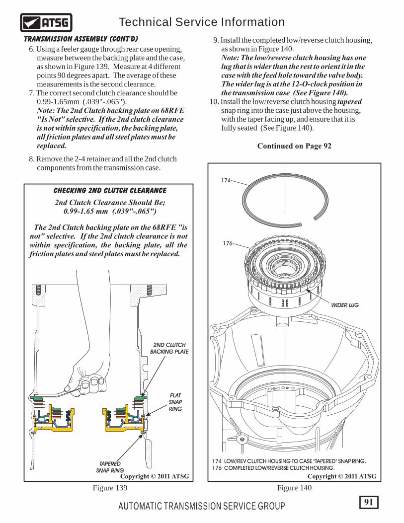
CHECKING 2ND CLUTCH CLEARANCE
TAPEREDSNAP RING
2ND CLUTCHBACKING PLATE
FLATSNAPRING
2nd Clutch Clearance Should Be;0.99-1.65 mm (.039"-.065")
The 2nd Clutch backing plate on the 68RFE "is not" selective. If the 2nd clutch clearance is not within specification, the backing plate, all the friction plates and steel plates must be replaced.
Continued on Page 92
TRANSMISSION ASSEMBLY (CONT'D)
6. Using a feeler gauge through rear case opening, measure between the backing plate and the case, as shown in Figure 139. Measure at 4 different points 90 degrees apart. The average of these measurements is the second clearance. 7. The correct second clutch clearance should be 0.99-1.65mm (.039"-.065"). Note: The 2nd Clutch backing plate on 68RFE "Is Not" selective. If the 2nd clutch clearance is not within specification, the backing plate, all friction plates and all steel plates must be replaced.
9. Install the completed low/reverse clutch housing, as shown in Figure 140. Note: The low/reverse clutch housing has one lug that is wider than the rest to orient it in the case with the feed hole toward the valve body. The wider lug is at the 12-O-clock position in the transmission case (See Figure 140). 10. Install the low/reverse clutch housing tapered snap ring into the case just above the housing, with the taper facing up, and ensure that it is fully seated (See Figure 140).
8. Remove the 2-4 retainer and all the 2nd clutch components from the transmission case.
174
176
WIDER LUG
174 LOW/REV CLUTCH HOUSING TO CASE "TAPERED" SNAP RING. 176 COMPLETED LOW/REVERSE CLUTCH HOUSING.
Figure 140Figure 139
Copyright © 2011 ATSG
91
Copyright © 2011 ATSG
AUTOMATIC TRANSMISSION SERVICE GROUP
Technical Service Information
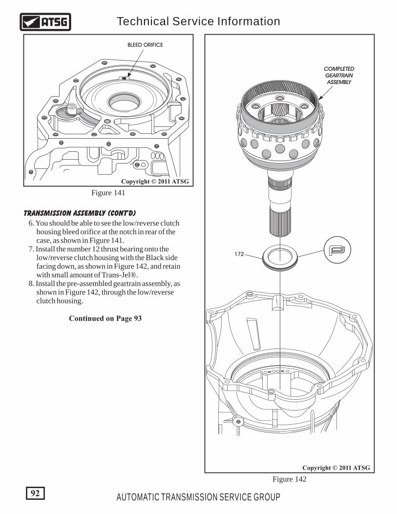
TRANSMISSION ASSEMBLY (CONT'D)
Continued on Page 93
Figure 141
Figure 142
Copyright © 2011 ATSG
BLEED ORIFICE
COMPLETEDGEARTRAINASSEMBLY
172
6. You should be able to see the low/reverse clutch housing bleed orifice at the notch in rear of the case, as shown in Figure 141. 7. Install the number 12 thrust bearing onto the low/reverse clutch housing with the Black side facing down, as shown in Figure 142, and retain with small amount of Trans-Jel®. 8. Install the pre-assembled geartrain assembly, as shown in Figure 142, through the low/reverse clutch housing.
92
Copyright © 2011 ATSG
AUTOMATIC TRANSMISSION SERVICE GROUP
Technical Service Information
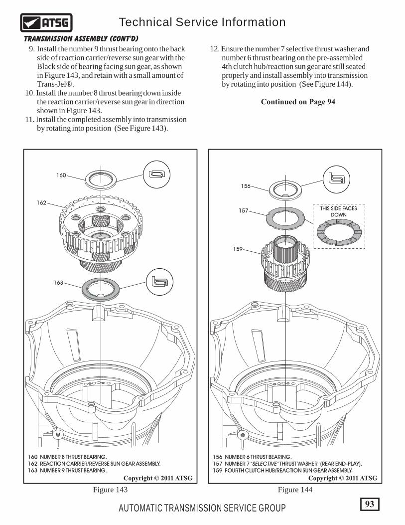
160 NUMBER 8 THRUST BEARING. 162 REACTION CARRIER/REVERSE SUN GEAR ASSEMBLY. 163 NUMBER 9 THRUST BEARING.
160
162
163
Figure 143 Figure 144
Copyright © 2011 ATSG
156 NUMBER 6 THRUST BEARING. 157 NUMBER 7 "SELECTIVE" THRUST WASHER (REAR END-PLAY). 159 FOURTH CLUTCH HUB/REACTION SUN GEAR ASSEMBLY.
156
157
159
TRANSMISSION ASSEMBLY (CONT'D)
Continued on Page 94
9. Install the number 9 thrust bearing onto the back side of reaction carrier/reverse sun gear with the Black side of bearing facing sun gear, as shown in Figure 143, and retain with a small amount of Trans-Jel®. 10. Install the number 8 thrust bearing down inside the reaction carrier/reverse sun gear in direction shown in Figure 143. 11. Install the completed assembly into transmission by rotating into position (See Figure 143).
12. Ensure the number 7 selective thrust washer and number 6 thrust bearing on the pre-assembled 4th clutch hub/reaction sun gear are still seated properly and install assembly into transmission by rotating into position (See Figure 144).
93
Copyright © 2011 ATSG
AUTOMATIC TRANSMISSION SERVICE GROUP
Technical Service Information
THIS SIDE FACESDOWN

Figure 146Figure 145
Continued on Page 95
TRANSMISSION ASSEMBLY (CONT'D)
151 SECOND CLUTCH STEEL PLATES (.130" THICK) (3 REQUIRED). 152 SECOND CLUTCH FRICTION PLATES (.090" THICK) (3 REQ). 153 SECOND CLUTCH BACKING PLATE (.325" THICK).
153
152
151
140 2-4 CLUTCH RETAINER ASSEMBLY. 154 2-4 RETAINER TO CASE "TAPERED" SNAP RING. 155 2-4 RETAINER TO CASE "FLAT" SNAP RING (.062" THICK).
155
154
140
13. Install the 2nd clutch backing plate into the case, as shown in Figure 145. 14. Install 2nd clutch pack beginning with a friction plate and alternating with a steel plate until you have 3 of each installed, as shown in Figure 145. Note: All clutch plates should be soaked for 30 minutes in proper fluid before assembly.
15. Install the 2-4 clutch retainer flat snap ring into lower groove in the case with snap ring opening facing the valve body area (See Figure 146).
94
Copyright © 2011 ATSGCopyright © 2011 ATSG
AUTOMATIC TRANSMISSION SERVICE GROUP
Technical Service Information
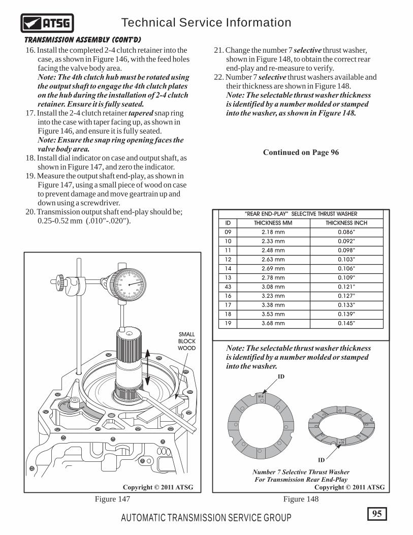
TRANSMISSION ASSEMBLY (CONT'D)
Figure 148Figure 147
Copyright © 2011 ATSG
16. Install the completed 2-4 clutch retainer into the case, as shown in Figure 146, with the feed holes facing the valve body area. Note: The 4th clutch hub must be rotated using the output shaft to engage the 4th clutch plates on the hub during the installation of 2-4 clutch retainer. Ensure it is fully seated. 17. Install the 2-4 clutch retainer tapered snap ring into the case with taper facing up, as shown in Figure 146, and ensure it is fully seated. Note: Ensure the snap ring opening faces the valve body area. 18. Install dial indicator on case and output shaft, as shown in Figure 147, and zero the indicator. 19. Measure the output shaft end-play, as shown in Figure 147, using a small piece of wood on case to prevent damage and move geartrain up and down using a screwdriver. 20. Transmission output shaft end-play should be; 0.25-0.52 mm (.010"-.020").
21. Change the number 7 selective thrust washer, shown in Figure 148, to obtain the correct rear end-play and re-measure to verify. 22. Number 7 selective thrust washers available and their thickness are shown in Figure 148. Note: The selectable thrust washer thickness is identified by a number molded or stamped into the washer, as shown in Figure 148.
SMALLBLOCKWOOD
0
0
1010
5050
2020
4040
3030
2.18 mm
2.33 mm
2.48 mm
2.63 mm
2.69 mm
2.78 mm
3.08 mm
3.23 mm
3.38 mm
3.53 mm
3.68 mm
0.086”
0.092”
0.098”
0.103”
0.106”
0.109”
0.121”
0.127”
0.133”
0.139”
0.145”
09
10
11
12
14
13
43
16
17
18
19
THICKNESS INCHTHICKNESS MM
“REAR END-PLAY” SELECTIVE THRUST WASHER
ID
Note: The selectable thrust washer thickness is identified by a number molded or stamped into the washer.
B14
B14
Number 7 Selective Thrust WasherFor Transmission Rear End-Play
ID
ID
Continued on Page 96
95
Copyright © 2011 ATSG
AUTOMATIC TRANSMISSION SERVICE GROUP
Technical Service Information

23. Install the number 5 thrust bearing and selective spacer onto back side of reverse clutch hub, as shown in Figure 149, and retain with Trans-Jel®. Note: Ensure that number 5 thrust bearing is fully snapped into selective spacer, as shown in Figure 150. This spacer is used to set front transmission end-play. 24. Install the number 1 thrust bearing, in direction shown in Figure 149, down into the pocket of the completed input housing. 25. Install the completed input housing and bearings into transmission case, as shown in Figure 149, by rotating back and forth until fully seated. Note: The input housing is fully seated when the teeth on input clutch hub are centered in the input speed sensor bore (See Figure 151).
TRANSMISSION ASSEMBLY (CONT'D)
Continued on Page 97
COMPLETEDINPUT CLUTCH
HOUSING ASSEMBLY
97
131 & 132
(131) (132)
NUMBER 5THRUST BEARING
(ILL. NO. 131)
SELECTIVESPACER
(ILL. NO. 132)
3 Equally Spaced "Protrusions"Around The Outside Diameter
Snaps Into Selective Spacer
Copyright © 2011 ATSG
97 NUMBER 1 THRUST BEARING. 131 NUMBER 5 THRUST BEARING. 132 NUMBER 5 "SELECTIVE" THRUST BEARING SPACER.
Figure 149 Figure 150
96
Copyright © 2011 ATSG
AUTOMATIC TRANSMISSION SERVICE GROUP
Technical Service Information
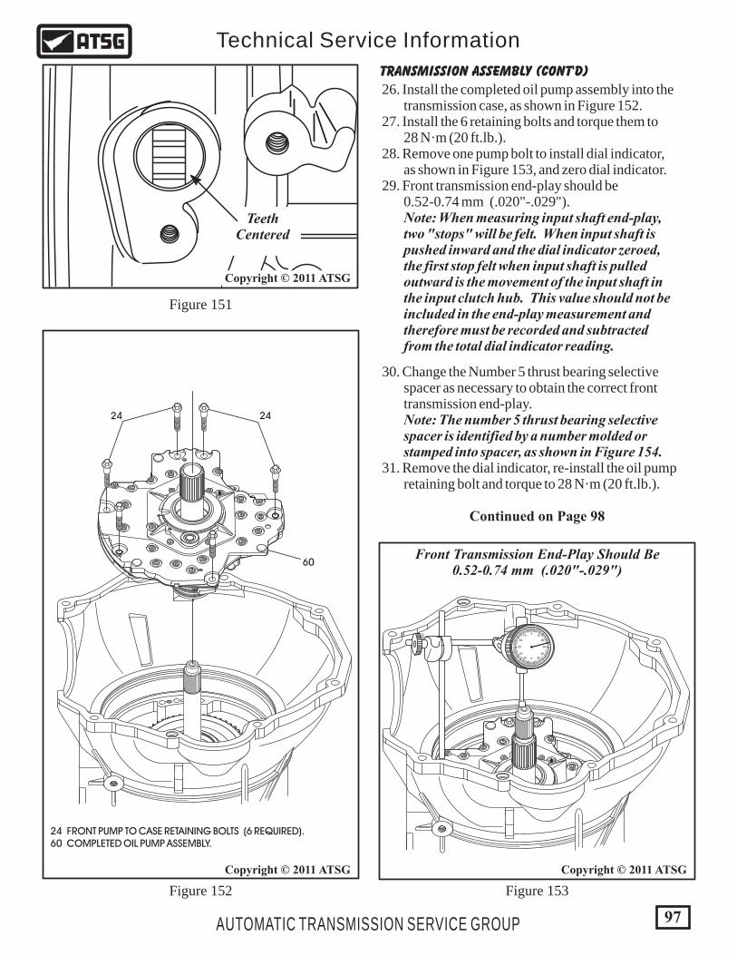
24 FRONT PUMP TO CASE RETAINING BOLTS (6 REQUIRED). 60 COMPLETED OIL PUMP ASSEMBLY.
Copyright © 2011 ATSG
26. Install the completed oil pump assembly into the transmission case, as shown in Figure 152. 27. Install the 6 retaining bolts and torque them to 28 N·m (20 ft.lb.). 28. Remove one pump bolt to install dial indicator, as shown in Figure 153, and zero dial indicator. 29. Front transmission end-play should be 0.52-0.74 mm (.020"-.029"). Note: When measuring input shaft end-play, two "stops" will be felt. When input shaft is pushed inward and the dial indicator zeroed, the first stop felt when input shaft is pulled outward is the movement of the input shaft in the input clutch hub. This value should not be included in the end-play measurement and therefore must be recorded and subtracted from the total dial indicator reading.
TRANSMISSION ASSEMBLY (CONT'D)
Continued on Page 98102
2424
60
102
0
0
1010
5050
2020
4040
3030
Front Transmission End-Play Should Be0.52-0.74 mm (.020"-.029")
Figure 152
Figure 151
Figure 153
30. Change the Number 5 thrust bearing selective spacer as necessary to obtain the correct front transmission end-play. Note: The number 5 thrust bearing selective spacer is identified by a number molded or stamped into spacer, as shown in Figure 154. 31. Remove the dial indicator, re-install the oil pump retaining bolt and torque to 28 N·m (20 ft.lb.).
97
Copyright © 2011 ATSG
AUTOMATIC TRANSMISSION SERVICE GROUP
Technical Service Information
TeethCentered
Copyright © 2011 ATSG
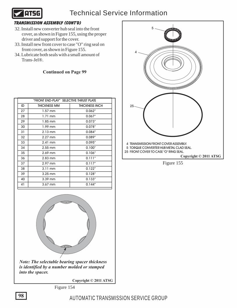
TRANSMISSION ASSEMBLY (CONT'D)
Figure 154
Figure 155
32. Install new converter hub seal into the front cover, as shown in Figure 155, using the proper driver and support for the cover. 33. Install new front cover to case "O" ring seal on front cover, as shown in Figure 155. 34. Lubricate both seals with a small amount of Trans-Jel®.
4 TRANSMISSION FRONT COVER ASSEMBLY. 5 TORQUE CONVERTER HUB METAL CLAD SEAL. 25 FRONT COVER TO CASE "O" RING SEAL.
5
4
25
1.57 mm
1.71 mm
1.85 mm
1.99 mm
2.13 mm
2.27 mm
2.41 mm
2.55 mm
2.69 mm
2.83 mm
2.97 mm
3.11 mm
3.25 mm
3.39 mm
3.67 mm
0.062”
0.067”
0.073”
0.078”
0.084”
0.089”
0.095”
0.100”
0.106”
0.111”
0.117”
0.122”
0.128”
0.133”
0.144”
27
28
29
30
31
32
33
34
35
36
37
38
39
40
41
THICKNESS INCHTHICKNESS MM
“FRONT END-PLAY” SELECTIVE THRUST PLATE
ID
Note: The selectable bearing spacer thickness is identified by a number molded or stamped into the spacer.
3 4
Continued on Page 99
98
Copyright © 2011 ATSG
Copyright © 2011 ATSG
AUTOMATIC TRANSMISSION SERVICE GROUP
Technical Service Information

120
Figure 156 Figure 157
3 TRANSMISSION FRONT COVER RETAINING SNAP RING. 4 TRANSMISSION FRONT COVER & CONVERTER SEAL ASSEMBLY.
3
4
TRANSMISSION ASSEMBLY (CONT'D)
35. Install the front cover and seal assembly into the transmission case, as shown in Figure 156. Note: Dodge has an installation tool available that allows this to be done without any damage to the front cover, as shown in Figure 157. 36. Install the front cover retaining snap ring into the groove in the case, as shown in Figure 156, and ensure it is fully seated.
Continued on Page 100
Copyright © 2011 ATSG
Front Cover Installation ToolDodge Part Number 9955
99
Copyright © 2011 ATSG
AUTOMATIC TRANSMISSION SERVICE GROUP
Technical Service Information
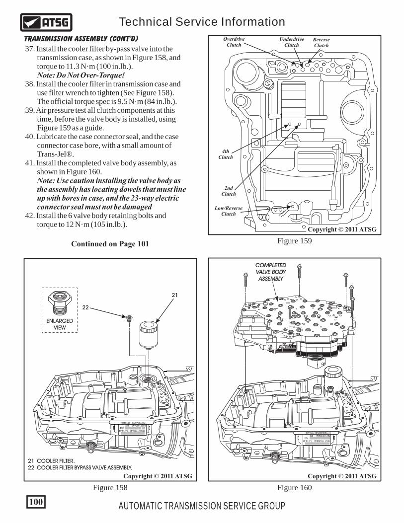
177720548P52119704AB
TITTJ177720548 14:10:44
P52119704AB RFE704
22
21
21 COOLER FILTER. 22 COOLER FILTER BYPASS VALVE ASSEMBLY.
ENLARGEDVIEW
Low/ReverseClutch
2ndClutch
4thClutch
OverdriveClutch
UnderdriveClutch
ReverseClutch
Copyright © 2011 ATSG
Figure 158 Figure 160
Figure 159
TRANSMISSION ASSEMBLY (CONT'D)
37. Install the cooler filter by-pass valve into the transmission case, as shown in Figure 158, and torque to 11.3 N·m (100 in.lb.). Note: Do Not Over-Torque! 38. Install the cooler filter in transmission case and use filter wrench to tighten (See Figure 158). The official torque spec is 9.5 N·m (84 in.lb.). 39. Air pressure test all clutch components at this time, before the valve body is installed, using Figure 159 as a guide. 40. Lubricate the case connector seal, and the case connector case bore, with a small amount of Trans-Jel®. 41. Install the completed valve body assembly, as shown in Figure 160. Note: Use caution installing the valve body as the assembly has locating dowels that must line up with bores in case, and the 23-way electric connector seal must not be damaged 42. Install the 6 valve body retaining bolts and torque to 12 N·m (105 in.lb.).
Continued on Page 101
Copyright © 2011 ATSG
COMPLETEDVALVE BODYASSEMBLY
1527
31657
13
1498
LOT 5LOT 5
10300023
479965505111
AK 1
98
177720548P52119704AB
TITTJ177720548 14:10:44
P52119704AB RFE704
100
Copyright © 2011 ATSG
AUTOMATIC TRANSMISSION SERVICE GROUP
Technical Service Information
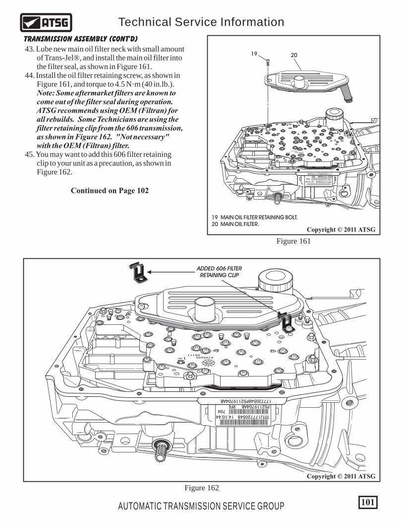
Figure 161
Figure 162
177720548P52119704AB
TITTJ177720548 14:10:44
P52119704AB RFE704
479965505111
AK 1
98
19 20
19 MAIN OIL FILTER RETAINING BOLT. 20 MAIN OIL FILTER.
Copyright © 2011 ATSG
43. Lube new main oil filter neck with small amount of Trans-Jel®, and install the main oil filter into the filter seal, as shown in Figure 161. 44. Install the oil filter retaining screw, as shown in Figure 161, and torque to 4.5 N·m (40 in.lb.). Note: Some aftermarket filters are known to come out of the filter seal during operation. ATSG recommends using OEM (Filtran) for all rebuilds. Some Technicians are using the filter retaining clip from the 606 transmission, as shown in Figure 162. "Not necessary" with the OEM (Filtran) filter. 45. You may want to add this 606 filter retaining clip to your unit as a precaution, as shown in Figure 162.
TRANSMISSION ASSEMBLY (CONT'D)
Continued on Page 102
177720548P52119704AB
TITTJ177720548 14:10:44
P52119704AB RFE704
479965505111
AK 1
98
ADDED 606 FILTERRETAINING CLIP
101
Copyright © 2011 ATSG
AUTOMATIC TRANSMISSION SERVICE GROUP
Technical Service Information
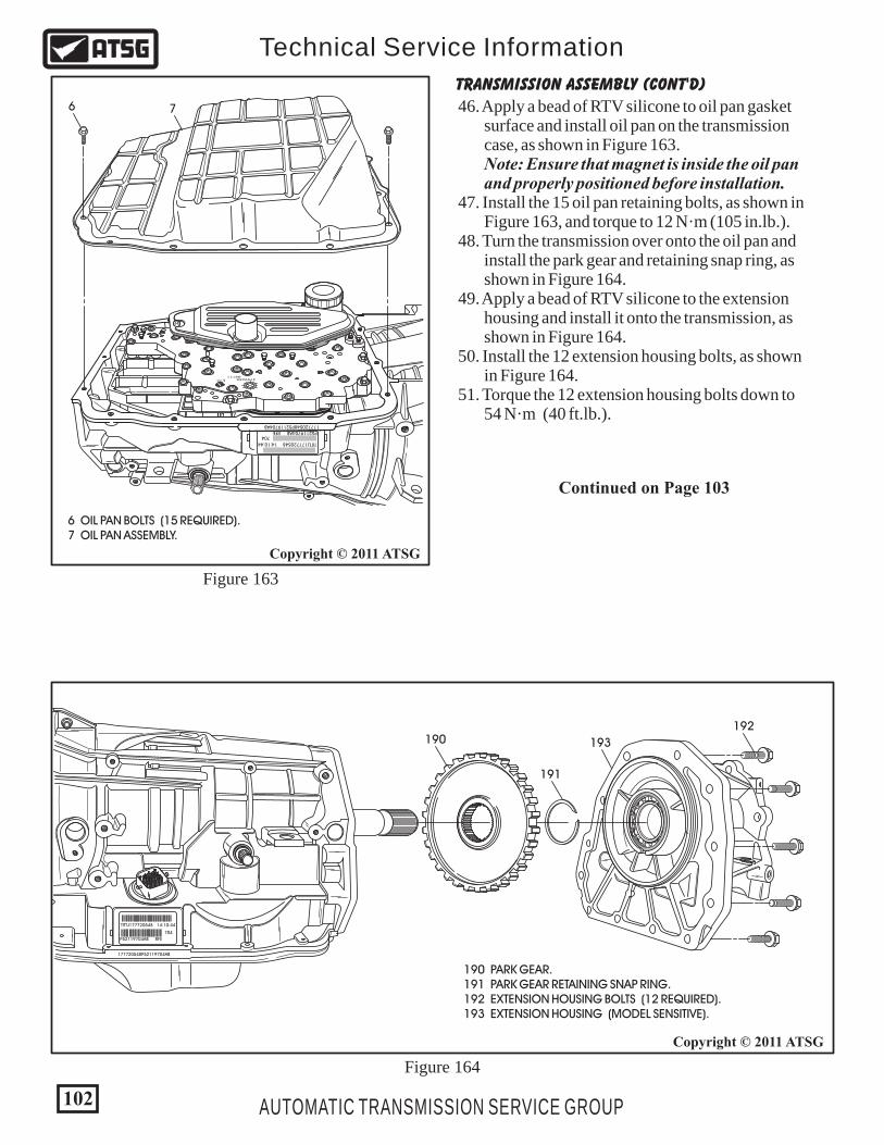
Figure 163
6 7
6 OIL PAN BOLTS (15 REQUIRED). 7 OIL PAN ASSEMBLY.
177720548P52119704AB
TITTJ177720548 14:10:44
P52119704AB RFE704
479965505111
AK 1
98
Figure 164
177720548P52119704AB
TITTJ177720548 14:10:44
P52119704AB RFE
704
190
191
192
193
190 PARK GEAR. 191 PARK GEAR RETAINING SNAP RING. 192 EXTENSION HOUSING BOLTS (12 REQUIRED). 193 EXTENSION HOUSING (MODEL SENSITIVE).
46. Apply a bead of RTV silicone to oil pan gasket surface and install oil pan on the transmission case, as shown in Figure 163. Note: Ensure that magnet is inside the oil pan and properly positioned before installation. 47. Install the 15 oil pan retaining bolts, as shown in Figure 163, and torque to 12 N·m (105 in.lb.). 48. Turn the transmission over onto the oil pan and install the park gear and retaining snap ring, as shown in Figure 164. 49. Apply a bead of RTV silicone to the extension housing and install it onto the transmission, as shown in Figure 164. 50. Install the 12 extension housing bolts, as shown in Figure 164. 51. Torque the 12 extension housing bolts down to 54 N·m (40 ft.lb.).
TRANSMISSION ASSEMBLY (CONT'D)
Continued on Page 103
102
Copyright © 2011 ATSG
Copyright © 2011 ATSG
AUTOMATIC TRANSMISSION SERVICE GROUP
Technical Service Information

Figure 167
Figure 166
Figure 165
177720548P52119704AB
TITTJ177720548 14:10:44
P52119704AB RFE
704
10 1211
13
15
14
Copyright © 2011 ATSG
10 INPUT SHAFT SPEED SENSOR. 11 INPUT SHAFT SPEED SENSOR "O" RING SEAL. 12 INPUT SHAFT SPEED SENSOR RETAINING BOLT. 13 OUTPUT SHAFT SPEED SENSOR. 14 OUTPUT SHAFT SPEED SENSOR "O" RING SEAL. 15 OUTPUT SHAFT SPEED SENSOR RETAINING BOLT.
16
SPEEDSENSOR
"O" RINGSEAL
RETAININGBOLT
17
18
Copyright © 2011 ATSG
16 LINE PRESSURE SENSOR. 17 LINE PRESSURE SENSOR "O" RING SEALS (2 REQUIRED). 18 LINE PRESSURE SENSOR RETAINING BOLT.
52. Install new "O" ring seals on both input and output speed sensors, as shown in Figure 165, and lube with small amount of Trans-Jel®. 53. Install both speed sensors into transmission case, as shown in Figure 166. 54. Torque both of the speed sensor bolts down to 12 N·m (105 in.lb.). 55. Install two new "O" ring seals on line pressure sensor & lube with small amount of Trans-Jel®, as shown in Figure 167. 56. Install line pressure sensor into the case bore, as shown in Figure 167, and torque the retaining bolt to 12 N·m (105 in.lb.).
TRANSMISSION ASSEMBLY (CONT'D)
Continued on Page 104
103
Copyright © 2011 ATSG
AUTOMATIC TRANSMISSION SERVICE GROUP
Technical Service Information

1 TORQUE CONVERTER ASSEMBLY.
1
Copyright © 2011 ATSG
57. Install a new dipstick tube seal into transmission case bore, as shown in Figure 168. 58. If they were removed, install both cooler line fittings into case, as shown in Figure 168, and torque to 17.5 N·m (13 ft.lb.). 59. Install new "O" ring seal on torque converter hub as shown in Figure 169, and lube hub with ATF. 60. Install torque converter, as shown in Figure 170, and while pushing in rotate converter until fully seated in pump gears.
61. Verify with straight edge and scale, as shown in Figure 171, face of converter lugs should be at least 25 mm (1.000") from face of case.
TRANSMISSION ASSEMBLY (CONT'D)
DIPSTICKTUBE SEAL
"O" RING
To CoolerFitting
From CoolerFitting
Copyright © 2011 ATSG
Figure 170
Figure 171
Figure 168
Figure 169
345 12
Approximately25 mm (1.000)
CONGRATULATIONSYOU ARE FINISHED!
104
Copyright © 2011 ATSG
Copyright © 2011 ATSG
AUTOMATIC TRANSMISSION SERVICE GROUP
Technical Service Information

25Torx
25Torx
25Torx
25Torx
30Torx
30Torx15 mm
8 mm 8 mm 8 mm
10 mm
15 mm
B C
DE
F
G
H
JK
L M
N
Bolts Drawn Actual Size
B. TRS SELECTOR PLATE TO VALVE BODY (1 REQUIRED). C. ACCUMULATOR COVER TO VALVE BODY (7 REQUIRED). C. PUMP SPACER PLATE TO PUMP BODY (2 REQUIRED). D. OIL PUMP BODY TO OIL PUMP COVER (24 REQUIRED). E. TRANSFER PLATE TO VALVE BODY, SILVER COLOR (50 REQUIRED). E. TRS/SOLENOID PACK COVER BOLTS, GOLD COLOR (6 REQUIRED). F. STATOR SUPPORT TO PUMP BODY (5 REQUIRED). G. OIL PAN TO TRANSMISSION CASE (15 REQUIRED). H. INPUT, OUTPUT, LINE PRESSURE SENSORS TO CASE (3 REQUIRED). J. VALVE BODY TO TRANSMISSION CASE (6 REQUIRED). K. OIL PUMP TO TRANSMISSION CASE (6 REQUIRED). L. EXTENSION HOUSING TO TRANSMISSION CASE (10 REQUIRED). M. EXTENSION HOUSING TO TRANSMISSION CASE (2 REQUIRED). N. MANUAL SHAFT RETAINING BOLT (1 REQUIRED).
BOLT IDENTIFICATION
END-PLAY SPECIFICATIONS
RECOMMENDED FLUID
Mopar® ATF Plus 4
Output Shaft End-Play ...................................................................................................... 0.25-0.52 mm (.010"-.020") Input Shaft End-Play ......................................................................................................... 0.52-0.74 mm (.020"-.029") Second Clutch Clearance ................................................................................................. 0.99-1.65 mm (.039"-.065") Fourth Clutch Clearance ................................................................................................... 0.77-1.39 mm (.030"-.055") Low/Reverse Clutch Clearance ........................................................................................ 1.18-2.09 mm (.046"-.082") Overdrive Clutch Clearance .............................................................................................. 0.75-1.61 mm (.030"-.063") Underdrive Clutch Clearance ........................................................................................... 1.02-1.72 mm (.040"-.068") Reverse Clutch Clearance ................................................................................................ 0.58-1.47 mm (.023"-.058")
Figure 173
Figure 172
105
Copyright © 2011 ATSG
AUTOMATIC TRANSMISSION SERVICE GROUP
Technical Service Information

68R
FE T
HR
UST
WASH
ER
AN
D T
HR
UST
BEAR
ING
LO
CATI
ON
Figure 174
No.
1N
o. 2
No.
3N
o. 4
No.
5N
o. 6
No.
7N
o. 8
No.
9N
o. 1
0N
o. 1
1N
o. 1
2
No.
12
No.
10
No.
8N
o. 6
No.
4N
o. 2
No.
11
No.
9N
o. 7
No.
5N
o. 3
No.
1
106
Copyright © 2011 ATSG
AUTOMATIC TRANSMISSION SERVICE GROUP
Technical Service Information
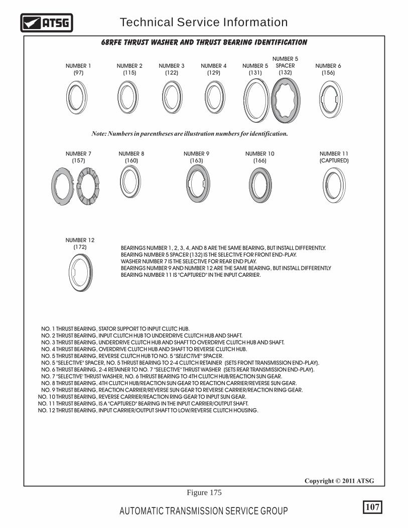
68RFE THRUST WASHER AND THRUST BEARING IDENTIFICATION
NUMBER 1(97)
NUMBER 7(157)
NUMBER 8(160)
NUMBER 9(163)
NUMBER 10(166)
NUMBER 11(CAPTURED)
NUMBER 12(172)
NUMBER 2(115)
NUMBER 3(122)
NUMBER 4(129)
NUMBER 5(131)
NUMBER 5SPACER(132)
NUMBER 6(156)
Figure 175
Note: Numbers in parentheses are illustration numbers for identification.
BEARINGS NUMBER 1, 2, 3, 4, AND 8 ARE THE SAME BEARING, BUT INSTALL DIFFERENTLY. BEARING NUMBER 5 SPACER (132) IS THE SELECTIVE FOR FRONT END-PLAY. WASHER NUMBER 7 IS THE SELECTIVE FOR REAR END PLAY. BEARINGS NUMBER 9 AND NUMBER 12 ARE THE SAME BEARING, BUT INSTALL DIFFERENTLY BEARING NUMBER 11 IS "CAPTURED" IN THE INPUT CARRIER.
NO. 1 THRUST BEARING, STATOR SUPPORT TO INPUT CLUTC HUB. NO. 2 THRUST BEARING, INPUT CLUTCH HUB TO UNDERDRIVE CLUTCH HUB AND SHAFT. NO. 3 THRUST BEARING, UNDERDRIVE CLUTCH HUB AND SHAFT TO OVERDRIVE CLUTCH HUB AND SHAFT. NO. 4 THRUST BEARING, OVERDRIVE CLUTCH HUB AND SHAFT TO REVERSE CLUTCH HUB. NO. 5 THRUST BEARING, REVERSE CLUTCH HUB TO NO. 5 "SELECTIVE" SPACER. NO. 5 "SELECTIVE" SPACER, NO. 5 THRUST BEARING TO 2-4 CLUTCH RETAINER (SETS FRONT TRANSMISSION END-PLAY). NO. 6 THRUST BEARING, 2-4 RETAINER TO NO. 7 "SELECTIVE" THRUST WASHER (SETS REAR TRANSMISSION END-PLAY). NO. 7 "SELECTIVE' THRUST WASHER, NO. 6 THRUST BEARING TO 4TH CLUTCH HUB/REACTION SUN GEAR. NO. 8 THRUST BEARING, 4TH CLUTCH HUB/REACTION SUN GEAR TO REACTION CARRIER/REVERSE SUN GEAR. NO. 9 THRUST BEARING, REACTION CARRIER/REVERSE SUN GEAR TO REVERSE CARRIER/REACTION RING GEAR. NO. 10 THRUST BEARING, REVERSE CARRIER/REACTION RING GEAR TO INPUT SUN GEAR. NO. 11 THRUST BEARING, IS A "CAPTURED" BEARING IN THE INPUT CARRIER/OUTPUT SHAFT. NO. 12 THRUST BEARING, INPUT CARRIER/OUTPUT SHAFT TO LOW/REVERSE CLUTCH HOUSING.
107
Copyright © 2011 ATSG
AUTOMATIC TRANSMISSION SERVICE GROUP
Technical Service Information

Copyright © 2011 ATSG
TORQUE SPECIFICATIONSComponent
Oil Pump Cover to Oil Pump Body Screws
Oil Pump Spacer Plate to Pump Body Screws
Oil Pump Assembly to Case
Stator Shaft Support to Pump Cover
Oil Pan to Case
Transfer Plate to TRS/Solenoid Pack Screws
Transfer Plate to Valve Body Screws
Accumulator Cover to Valve Body Screws
Detent Spring to Valve Body Screw
Valve Body to Case Bolts
TRS Selector Plate to Valve Body Screw
Input Speed Sensor to Case
Output Speed Sensor to Case
Line Pressure Sensor to Case
Extension Housing to Case
Pressure Test Plugs
Main Oil Filter Screw
Cooler Filter
Cooler Filter By-Pass Valve Assembly
Cooler Line Fittings to Case
Manual Shaft Retaining Bolt/Pin
N•m
4.5 40
4.5 40
28
11.8
11.8
5.7 50
4.5 40
4.5 40
4.5
12
4.5
11.8
11.8
11.8
54
5.1
4.5
9.5
11.3
17.5
28
Ft.Lb.
105
40
105
105
105
40
45
40
84
100
13
20
In.Lb.
20
105
105
40
Figure 176
108 AUTOMATIC TRANSMISSION SERVICE GROUP
Technical Service Information
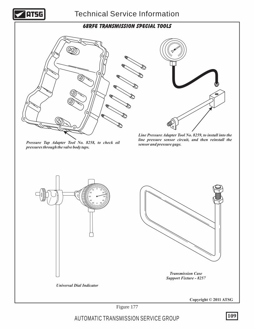
Figure 177
Pressure Tap Adapter Tool No. 8258, to check oil pressures through the valve body taps.
Line Pressure Adapter Tool No. 8259, to install into the line pressure sensor circuit, and then reinstall the sensor and pressure gage.
lllll ll ll ll ll ll ll ll ll ll ll ll ll ll ll ll ll ll llll llll ll
0
0
1010
5050
2020
4040
3030
Universal Dial Indicator
Transmission CaseSupport Fixture - 8257
68RFE TRANSMISSION SPECIAL TOOLS
109
Copyright © 2011 ATSG
AUTOMATIC TRANSMISSION SERVICE GROUP
Technical Service Information
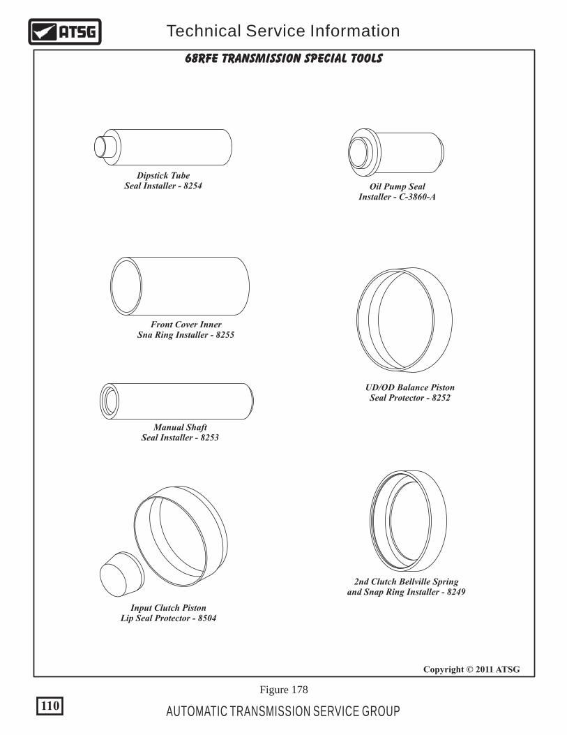
Figure 178
Dipstick TubeSeal Installer - 8254 Oil Pump Seal
Installer - C-3860-A
Front Cover InnerSna Ring Installer - 8255
UD/OD Balance PistonSeal Protector - 8252
2nd Clutch Bellville Springand Snap Ring Installer - 8249
Input Clutch PistonLip Seal Protector - 8504
Manual ShaftSeal Installer - 8253
68RFE TRANSMISSION SPECIAL TOOLS
110
Copyright © 2011 ATSG
AUTOMATIC TRANSMISSION SERVICE GROUP
Technical Service Information
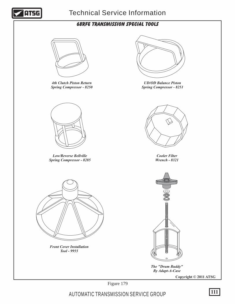
Figure 179
68RFE TRANSMISSION SPECIAL TOOLS
Low/Reverse BellvilleSpring Compressor - 8285
Cooler FilterWrench - 8321
The "Drum Buddy"By Adapt-A-Case
UD/OD Balance PistonSpring Compressor - 8251
4th Clutch Piston ReturnSpring Compressor - 8250
Front Cover InstallationTool - 9955
111
Copyright © 2011 ATSG
AUTOMATIC TRANSMISSION SERVICE GROUP
Technical Service Information
APT
A-CA
DA-
SE

185 LOW SPRAG OUTER RACE. 186 LOW SPRAG THRUST PLATES (2 REQUIRED). 187 LOW SPRAG END BREARINGS (2 REQUIRED). 188 LOW SPRAG ASSEMBLY (36 ELEMENTS). 189 LOW SPRAG INNER RACE. 190 LOW SPRAG RETAINING SNAP RING.
112
Copyright © 2011 ATSGCopyright © 2011 ATSG
AUTOMATIC TRANSMISSION SERVICE GROUP
Technical Service Information
Roller Length = .702"Roller Diameter = .357"
OriginalOEM Part
OriginalOEM Part
OriginalOEM Part
New Part
New Part
Roller Number = 14Element Length = .502"Element Number = 36
185
186
186
187
187
188
190
189
Figure 180 Figure 181
HEAVY DUTY LOW ROLLER CLUTCH
There have been reports that the rear sprag has a tendency to "Flip" if any type of engine performance products have been installed. There is available from Suncoast Products a heavy duty low roller clutch to replace the low sprag and comes complete, ready to install. We have provided you with the dimensions of both so that you can make the decision of whether or not it is needed for your application.
OEM Low Sprag Dimensions
Suncoast Low Roller Dimensions