2011 Dodge Ram 1500 brought to you by your Mid Atlantic Dodge Ram dealer
WESTERN PRODUCTS, P.O. BOX 245038, MILWAUKEE, WI 53224-9538
Lit. No. 63813September 10, 2003
Dodge Ram 1500 4x4 2002 & LaterDodge Ram 2500/3500 2003 & Later
Vehicle Specific ElectricalInstallation Instructions
Model No. 959 and Model No. 969
CAUTIONSee your WESTERN® outlet for applicationrecommendations. The Selection List has specificvehicle and snowplow requirements.
CAUTIONRead this document before installing the snowplow.
A DIVISION OF DOUGLAS DYNAMICS, L.L.C.
Straight Blades (Model 959 and 969)Hydraulics Box No. 56588
All Years and ModelsHarness Kit No. 64053
Headlamp Kit No. 64078
MVP® Blades (Model 969)Hydraulics Box No. 56777
Harness Kit 64054Headlamp Kit No. 64078

TABLE OF CONTENTS
SAFETY ...................................................................... 1Safety Definitions .................................................. 1Battery Safety ...................................................... 1Torque Chart ......................................................... 1
UNDER HOOD INSTALLATION .................................. 2Harness Kit Selection ........................................... 2
Straight Blade................................................. 2MVP® Blade ................................................... 2
Vehicle Harness and Motor Relay ......................... 2Plug-in Harness and Headlamp Relay Installation .... 6
WIRING DIAGRAM ..................................................... 72002 & Later Ram 1500 with Dual HB-52003 & Later Ram 2500/3500 with Dual HB-564053 or 64054 Harness Kit with 12-Pin (White)Headlamps ........................................................... 72002 Ram 1500 with Dual HB-5 without DRL’s63427 Harness Kit 9-Pin Headlamps .................... 82002 Ram 1500 with Dual HB-5-G with DRL’s63427 Harness Kit 9-Pin Headlamps .................... 9
Lit. No. 63813 September 10, 2003
MVP® IN-CAB CONTROL WIRING ........................... 10Headlamp Kit Harness Modification .................... 10MVP® Installations Only ..................................... 10
ELECTRICAL SCHEMATIC....................................... 14MVP® Blade - Electrical Schematic .................... 14
12-PIN HEADLAMP KIT MODIFICATION ................. 1561550-1 Headlamp Kit 12-Pinand 64078 Headlamp Kit 12-Pin White................ 15
WIRING DIAGRAM - 61185 PARK OR TURNHARNESS KIT....................................................... 16
Turn Signal Application ....................................... 16Cab Marker / Park Lamps Application ................. 16
1Lit. No. 63813 September 10, 2003
SAFETY
SAFETY DEFINITIONS
NOTE: Identifies tips, helpful hints andmaintenance information the owner/operatorshould know.
WARNINGIndicates a potentially hazardous situation that,if not avoided, could result in death or seriouspersonal injury.
CAUTIONIndicates a situation that, if not avoided, couldresult in damage to product or property.
BATTERY SAFETY
CAUTIONAlways disconnect the battery before removingor replacing electrical components such as amotor relay or battery cable.
CAUTIONBatteries normally produce explosive gaseswhich can cause personal injury. Therefore, donot allow flames, sparks or lit tobacco to comenear the battery. When charging or workingnear a battery, always cover your face andprotect your eyes, and also provide ventilation.Batteries contain sulfuric acid which burns skin,eyes and clothing.Disconnect the battery before removing orreplacing any electrical components.
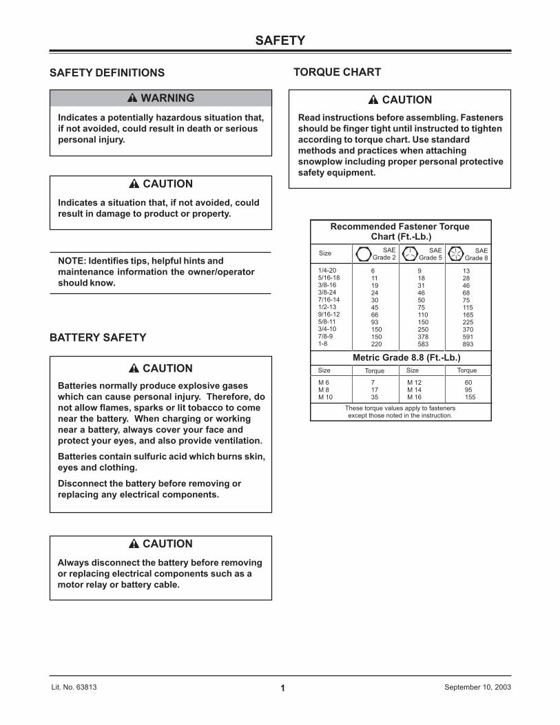
TORQUE CHART
Recommended Fastener Torque Chart (Ft.-Lb.)
SizeSAE
Grade 2SAE
Grade 5SAE
Grade 8
1/4-205/16-183/8-163/8-247/16-141/2-139/16-125/8-11 3/4-10 7/8-9 1-8
611192430456693150150220
91831465075110150250378583
1328 46 68 75 115 165 225 370 591 893
Metric Grade 8.8 (Ft.-Lb.)
Size TorqueSizeTorque
M 6M 8M 10
M 12M 14M 16
717 35
60 95 155
These torque values apply to fastenersexcept those noted in the instruction.
CAUTIONRead instructions before assembling. Fastenersshould be finger tight until instructed to tightenaccording to torque chart. Use standardmethods and practices when attachingsnowplow including proper personal protectivesafety equipment.
2Lit. No. 63813 September 10, 2003
UNDER HOOD INSTALLATION
(Continued on next page)
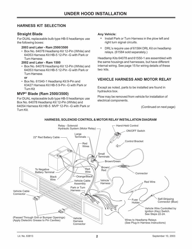
HARNESS, SOLENOID CONTROL & MOTOR RELAY INSTALLATION DIAGRAM
22" Red Battery Cable
Red Wires
Large Terminals
Relay - SolenoidHydraulic System (Motor Relay)
SmallTerminals
Brown/Green
Brown/Red
Orange/Black
Vehicle Harness
Vehicle Cable Assembly
Black Wire
To Negative Battery Terminal
Hand-Held Control
ON/OFF Switch
Control Bracket
Connector
Red Wire
Self-Stripping Connector (Blue)
Vehicle Wire Controlled byIgnition (Key) Switch. See Steps 22-24.
Wires to Headlamp Relays(See Plug-In Harness Instructions)
Vehicle Harness Connector
Vehicle Cable Connector
Fuse Holder
Red Wire
(Passed Through Grill or Bumper Openings)(Apply Dielectric Grease to Pin Cavities)
Park or Turn Harness
VEHICLE HARNESS AND MOTOR RELAY
Except as noted, parts to be installed are found inhydraulics box.
Plow may be removed from vehicle for installation ofelectrical components.
HARNESS KIT SELECTION
Straight BladeFor DUAL replaceable bulb type HB-5 headlamps usethe following boxes:
2003 and Later - Ram 2500/3500• Box No. 64078 Headlamp Kit 12-Pin (White) and
64053 Harness Kit HB-5 12-Pin -G with Park orTurn Harness
2002 and Later - Ram 1500• Box No. 64078 Headlamp Kit 12-Pin (White) and
64053 Harness Kit HB-5 12-Pin -G with Park orTurn Harnessor
• Box No. 61540-1 Headlamp Kit 9-Pin and63427 Harness Kit HB-5 9-Pin -G with Park orTurn Kit
MVP® Blade (Ram 2500/3500)For DUAL replaceable bulb type HB-5 headlamps useBox No. 64078 Headlamp Kit 12-Pin (White) and64054 Harness Kit HB-5 MVP 12-Pin -G with Park orTurn Kit.
Any Vehicle:• Install Park or Turn Harness in the plow left and
right turn signal circuits.
• DRL’s require use of 61584 DRL Kit on headlamprelays. (61584 sold separately.)
Headlamp Kits 64078 and 61550-1 are assembled withthe same housings and harnesses, but have differentinternal wiring. See page 15 for wiring details of thesetwo kits.
3Lit. No. 63813 September 10, 2003
VEHICLE HARNESS AND MOTOR RELAY(Continued)
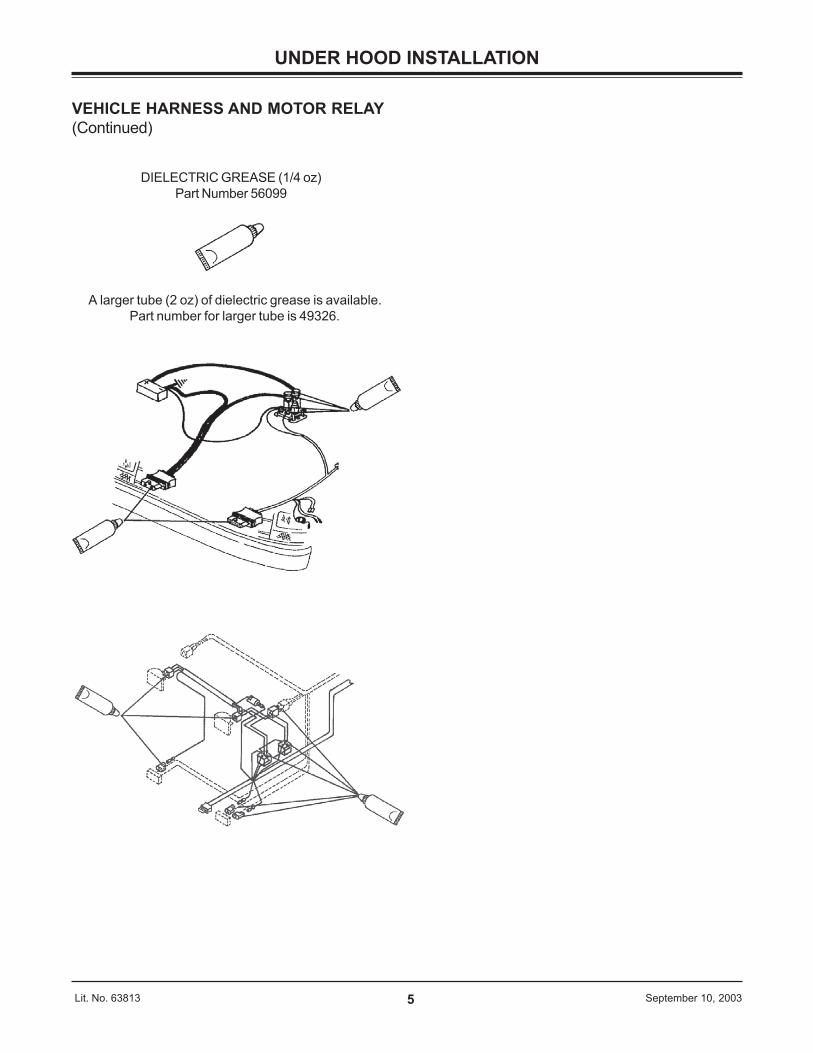
NOTE: Use dielectric grease to preventcorrosion on all under hood electricalconnections. Fill receptacles and lightly coatring terminals and blades before assembly.
NOTE: During electrical installation, the LONGBATTERY GROUND CABLE (no stripe) MUST BEGROUNDED TO THE NEGATIVE BATTERYTERMINAL.
1. Identify wires for the parking lamp on the driver-sideand the turn signals on both sides of the vehicle.Attach a black self-stripping bullet receptacleconnector (found in harness kit) to each of thesethree wires.
2. Remove NEGATIVE battery cable from battery.
3. Find a location for the motor relay where it will beprotected from road splash and within 18" of thevehicle primary battery.
NOTE: Motor relay terminals must be up orhorizontal.
4. Using the motor relay base as a template, drill two9/32" holes, and mount motor relay to holes using1/4" x 3/4" bolts, flat washers and lock nuts.
5. Route 22" battery cable between a large motor relayterminal and the POSITIVE battery terminal takingcare to avoid sharp edges and hot or moving parts.
6. Position the insulated end (box) of the park or turnharness (found in harness kit) in the area behind thedriver side headlamp. Route the red wire with thefuse holder to either the large terminal on the motorrelay with the 22" battery cable on it, or to theclamp of the positive post of the battery.Route the park or turn harness black wire with ringterminal to the negative post clamp of the battery.Do not connect at this time.
7. Attach cable to motor relay terminal with a lockwasher and a 5/16"-24 jam nut. Attach cable tobattery POSITIVE terminal fastener.
UNDER HOOD INSTALLATION
(Continued on next page)
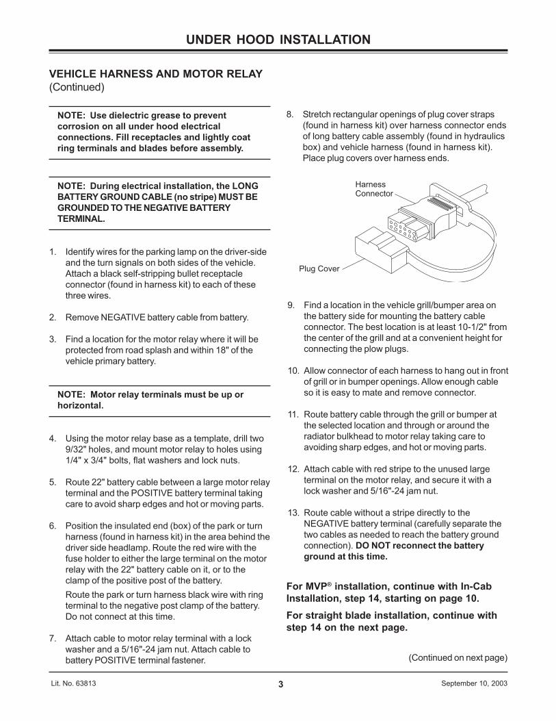
8. Stretch rectangular openings of plug cover straps(found in harness kit) over harness connector endsof long battery cable assembly (found in hydraulicsbox) and vehicle harness (found in harness kit).Place plug covers over harness ends.
Harness Connector
Plug Cover
9. Find a location in the vehicle grill/bumper area onthe battery side for mounting the battery cableconnector. The best location is at least 10-1/2" fromthe center of the grill and at a convenient height forconnecting the plow plugs.
10. Allow connector of each harness to hang out in frontof grill or in bumper openings. Allow enough cableso it is easy to mate and remove connector.
11. Route battery cable through the grill or bumper atthe selected location and through or around theradiator bulkhead to motor relay taking care toavoiding sharp edges, and hot or moving parts.
12. Attach cable with red stripe to the unused largeterminal on the motor relay, and secure it with alock washer and 5/16"-24 jam nut.
13. Route cable without a stripe directly to theNEGATIVE battery terminal (carefully separate thetwo cables as needed to reach the battery groundconnection). DO NOT reconnect the batteryground at this time.
For MVP® installation, continue with In-CabInstallation, step 14, starting on page 10.For straight blade installation, continue withstep 14 on the next page.
4Lit. No. 63813 September 10, 2003
22. Remove the knee panel below the steering column.Next, remove the bezel (heater control and mappocket are part of the bezel) from around the radioand air vents by removing the screw in the lowerright corner. Gently pull out on the hook below thescrew to release the spring clips that retain thebezel. There are two spring clips at the top (eitherside of the radio), two spring clips in the middle(either side of the heater control) and six clips alongthe bottom. Hold down the release tabs to removethe four connectors from the back of the bezel foreasy access to the cigar lighter wires.
23. Route the plow vehicle harness red wire with fuseholder to the opening with the cigar lighter wires init. Route carefully to avoid sharp edges which cancut the wire insulation. Leave enough wire so thefuse holder can be serviced from the opening underthe steering column. Trim excess red wire and jointhe plow vehicle harness fuse holder read wire tothe red wire for the cigar lighter.
24. Open blue self stripping connector and place theend of the fuse holder red wire against the innergroove stop (end of wire must not extend from theclosed connector, and the cigar lighter wire in theouter groove.) Close connector over the wires usinga pliers and snap the locking tab in place. Repeatwith DRL pink wire.
Operating the plow control may require up to 7 amps ofcurrent. Using the plow control, while the cigar lighter orother large power consumer plugged into the lighteropening is in use, may “blow” the fuse due to the largecurrent draw. Replace a blown fuse with the same sizefuse (cigar lighter circuit is 20 amps). Installing anoversized fuse may allow the wires to overheat resultingin a damaged vehicle wiring harness.
25. Reconnect vehicle ground cable to NEGATIVEbattery terminal along with the all black plowbattery cable, orange/black wire, and the smallblack park or turn harness wire.
UNDER HOOD INSTALLATION
(Continued on next page)
VEHICLE HARNESS AND MOTOR RELAY(Continued)
For Straight Blades Only
14. Find a grill/bumper area location on driver-side forthe vehicle harness (similar position to battery cablemount). See Steps 9 and 10 above for how toinstall. Route vehicle harness through grill orbumper and around, or through radiator bulkhead(drill 5/8" hole if needed) into engine compartment.
15. Route the wires that break out of the vehicleharness to the area behind the driver-sideheadlamp. Route rest of harness to the firewall. Drilla 5/8" hole through the firewall in a convenientlocation away from hot or moving engine parts.
16. All vehicles with DRL’s - Insert fuse holder on pinkwire of DRL Adapter Kit (P.N. 61584) through firewallfirst. Route end of pink wire with receptacles to areaof driver-side headlamp.
17. Route brown/red and orange/black wire loom tomotor relay.
18. Attach the brown/red and orange/black wires smallring terminals to separate small terminals on motorrelay using a lock washer and #10-32 nut for eachconnection.
19. Route the 24" long orange/black wire with 3/8" ringterminal to battery NEGATIVE post. DO NOTattach wire to battery at this time.
20. Feed vehicle harness fuse holder through hole andthen feed the plastic connector and harness throughto the cab. Disassembly of the fuse holder maymake it easier to pass through 5/8" hole.
21. Inside the cab, route vehicle harness connector tosolenoid or CabCommand control and couple theconnectors together.
5Lit. No. 63813 September 10, 2003
UNDER HOOD INSTALLATION
VEHICLE HARNESS AND MOTOR RELAY(Continued)
A larger tube (2 oz) of dielectric grease is available.Part number for larger tube is 49326.
DIELECTRIC GREASE (1/4 oz)Part Number 56099
6Lit. No. 63813 September 10, 2003
UNDER HOOD INSTALLATION
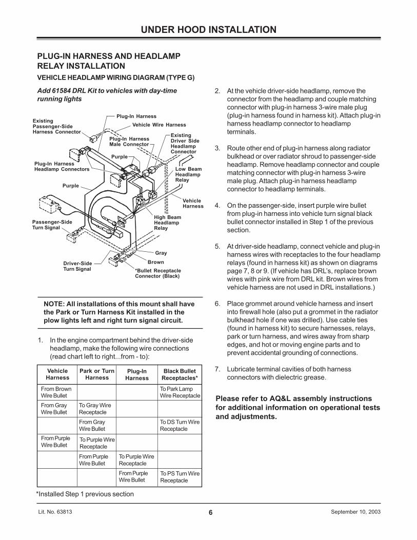
PLUG-IN HARNESS AND HEADLAMPRELAY INSTALLATIONVEHICLE HEADLAMP WIRING DIAGRAM (TYPE G)
Add 61584 DRL Kit to vehicles with day-timerunning lights
NOTE: All installations of this mount shall havethe Park or Turn Harness Kit installed in theplow lights left and right turn signal circuit.
1. In the engine compartment behind the driver-sideheadlamp, make the following wire connections(read chart left to right...from - to):
2. At the vehicle driver-side headlamp, remove theconnector from the headlamp and couple matchingconnector with plug-in harness 3-wire male plug(plug-in harness found in harness kit). Attach plug-inharness headlamp connector to headlampterminals.
3. Route other end of plug-in harness along radiatorbulkhead or over radiator shroud to passenger-sideheadlamp. Remove headlamp connector and couplematching connector with plug-in harness 3-wiremale plug. Attach plug-in harness headlampconnector to headlamp terminals.
4. On the passenger-side, insert purple wire bulletfrom plug-in harness into vehicle turn signal blackbullet connector installed in Step 1 of the previoussection.
5. At driver-side headlamp, connect vehicle and plug-inharness wires with receptacles to the four headlamprelays (found in harness kit) as shown on diagramspage 7, 8 or 9. (If vehicle has DRL’s, replace brownwires with pink wire from DRL kit. Brown wires fromvehicle harness are not used in DRL installations.)
6. Place grommet around vehicle harness and insertinto firewall hole (also put a grommet in the radiatorbulkhead hole if one was drilled). Use cable ties(found in harness kit) to secure harnesses, relays,park or turn harness, and wires away from sharpedges, and hot or moving engine parts and toprevent accidental grounding of connections.
7. Lubricate terminal cavities of both harnessconnectors with dielectric grease.
Please refer to AQ&L assembly instructionsfor additional information on operational testsand adjustments.
ExistingPassenger-SideHarness Connector
Plug-In HarnessVehicle Wire Harness
Plug-In HarnessHeadlamp Connectors
Purple
Passenger-SideTurn Signal
VehicleHarness
Gray
Brown*Bullet ReceptacleConnector (Black)
Driver-SideTurn Signal
Purple
ExistingDriver SideHeadlampConnector
High BeamHeadlampRelay
Low BeamHeadlampRelay
Plug-In HarnessMale Connector
VehicleHarness
Park or TurnHarness
Plug-InHarness
Black BulletReceptacles*
From BrownWire Bullet
To Park LampWire Receptacle
From GrayWire Bullet
To Gray WireReceptacle
From PurpleWire Bullet
From GrayWire Bullet
To Purple WireReceptacle
To DS Turn WireReceptacle
From PurpleWire Bullet
To Purple WireReceptacleFrom PurpleWire Bullet
To PS Turn WireReceptacle
*Installed Step 1 previous section
7Lit. N
o. 63813Septem
ber 10, 2003
87
86 85
87a
30
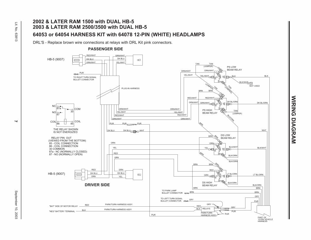
2002 & LATER RAM 1500 with DUAL HB-52003 & LATER RAM 2500/3500 with DUAL HB-5
64053 or 64054 HARNESS KIT with 64078 12-PIN (WHITE) HEADLAMPS
DRL'S - Replace brown wire connections at relays with DRL Kit pink connectors.
30
87
aTO RIGHT TURN SIGNAL
BULLET CONNECTOR
PARK/TURN HARNESS ASSY.
PARK/TURN HARNESS ASSY.
RED/WHT
YEL/WHT
GRN/WHT
ORN/WHT
GRN
YEL
DK BLU
DRIVER SIDE
ORN
"BAT" SIDE OF MOTOR RELAY
"NEG" BATTERY TERMINAL
RED
BLK
RELAY PIN OUT (VIEWED FROM THE BOTTOM) 85 - COIL CONNECTION 86 - COIL CONNECTION 30 COMMON 87a - NC (NORMALLY CLOSED) 87 - NO (NORMALLY OPEN)
HB-5 (9007)
THE RELAY SHOWN IS NOT ENERGIZED
DK BLU
RED
RED
GRN
YEL
ORN
DK BLU
COM
COILCOIL
NO
NC
PUR
87
a
30
RELAYS
PARK/TURN
HARNESS ASSY.
DS HIGH
BEAM RELAY
PUR
TO LEFT TURN SIGNAL
BULLET CONNECTOR
BLK
RED
TO PARK LAMP
BULLET CONNECTOR
GRY
BRN
BRN
PUR
GRY
GRY
PUR
85
BLK/ORN
12-PIN VEHICLEHARNESS
PART OF
PUR
BRN
GRY
BLK/ORN
BRN
GRN/WHT
PS HIGH
BEAM RELAY
WHTDK BLU
PURPUR
PLUG-IN HARNESS
GRN/WHT
YEL/WHT
RED/WHT
GRN/WHT
ORN/WHT
RED/WHT
RED
GRN
86
87
85
LT BL/ORN
BLK/ORN
BLK/ORN
DS LOW
BEAM RELAY
YEL
ORN
87
a
30
87
86
BLK/WHT
LT BL/ORN
BLK/WHT
WHT
BLK/WHT
DK BL/ORN
85
30
87
a
87
BLK
/ORN
TAN
(JUMPER)
(JUM
PER)
RED/WHT 86
TAN
(JUMPER)
85
TAN
DK BL/ORN
NOT USED
DK BLU
GRN/WHT
YEL/WHT
PASSENGER SIDE
HB-5 (9007)
PUR
RED/WHT
DK BLU
ORN/WHT
YEL/WHT
ORN/WHT
YEL/WHT
TAN
(JUMPER)
ORN/WHT 86
87
TAN
PS LOW
BEAM RELAY
BLK BLK
BRN BRNBRN
BRN
BRN BRN
BRN
BRN BRN
WIR
ING
DIA
GR
AM

8Lit. N
o. 63813Septem
ber 10, 2003
WIR
ING
DIA
GR
AM
2002 RAM 1500 with DUAL HB-5 without DRL's
63427 HARNESS KIT with 61540-1 9-PIN HEADLAMPS
DRIVER SIDE
PASSENGER SIDE
9Lit. N
o. 63813Septem
ber 10, 2003
WIR
ING
DIA
GR
AM
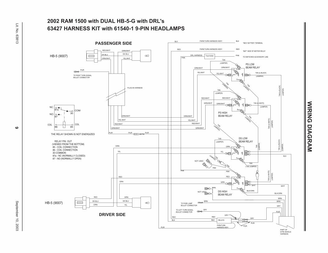
2002 RAM 1500 with DUAL HB-5-G with DRL's
63427 HARNESS KIT with 61540-1 9-PIN HEADLAMPS
DRIVER SIDE
PASSENGER SIDE
10Lit. No. 63813 September 10, 2003
MVP® IN-CAB CONTROL WIRING - CONTINUED FROM PAGE 3
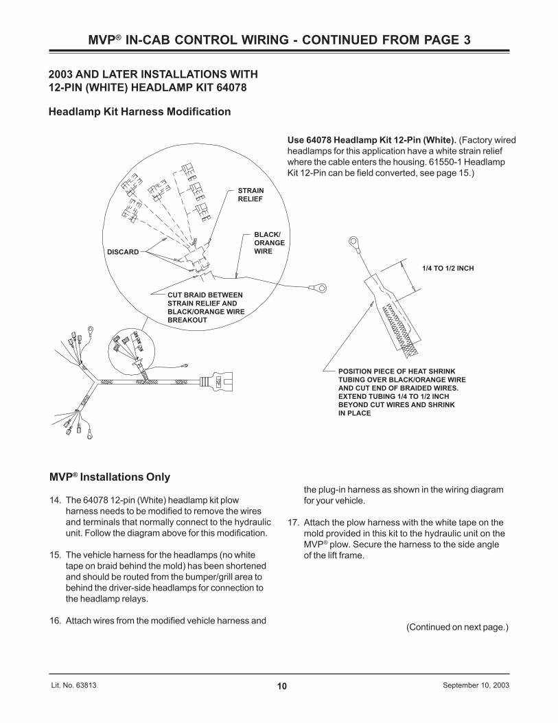
2003 AND LATER INSTALLATIONS WITH12-PIN (WHITE) HEADLAMP KIT 64078
Headlamp Kit Harness Modification
STRAIN
RELIEF
BLACK/
ORANGE
WIREDISCARD
CUT BRAID BETWEEN
STRAIN RELIEF AND
BLACK/ORANGE WIRE
BREAKOUT
1/4 TO 1/2 INCH
POSITION PIECE OF HEAT SHRINK
TUBING OVER BLACK/ORANGE WIRE
AND CUT END OF BRAIDED WIRES.
EXTEND TUBING 1/4 TO 1/2 INCH
BEYOND CUT WIRES AND SHRINK
IN PLACE
the plug-in harness as shown in the wiring diagramfor your vehicle.
17. Attach the plow harness with the white tape on themold provided in this kit to the hydraulic unit on theMVP® plow. Secure the harness to the side angleof the lift frame.
MVP® Installations Only
14. The 64078 12-pin (White) headlamp kit plowharness needs to be modified to remove the wiresand terminals that normally connect to the hydraulicunit. Follow the diagram above for this modification.
15. The vehicle harness for the headlamps (no whitetape on braid behind the mold) has been shortenedand should be routed from the bumper/grill area tobehind the driver-side headlamps for connection tothe headlamp relays.
16. Attach wires from the modified vehicle harness and(Continued on next page.)
Use 64078 Headlamp Kit 12-Pin (White). (Factory wiredheadlamps for this application have a white strain reliefwhere the cable enters the housing. 61550-1 HeadlampKit 12-Pin can be field converted, see page 15.)
11Lit. No. 63813 September 10, 2003
MVP® IN-CAB CONTROL WIRING - CONTINUED FROM PAGE 3
22" Red Battery Cable
Red Wires
Large Terminals
Relay - SolenoidHydraulic System (Motor Relay)
SmallTerminals
Brown/Green
Brown/Red
Orange/Black
Vehicle Harness
Vehicle Cable Assembly
Black Wire
To Negative Battery Terminal
Hand-Held Control
ON/OFF Switch
Control Bracket
Connector
Red Wire
Self-Stripping Connector (Blue)
Vehicle Wire Controlled byIgnition (Key) Switch. See Steps 31-33.
Wires to Headlamp Relays(See Plug-In Harness Instructions)
Vehicle Harness Connector – Headlmaps(Passed Through Grill or Bumper Openings)(Apply Dielectric Grease to Pin Cavities)
Vehicle Cable Connector
Fuse Holder
Red Wire
Park or Turn Harness
Vehicle Harness Connector – Control (White Tape)(Passed Through Grill or Bumper Openings)(Apply Dielectric Grease to Pin Cavities)
MVP® Installations Only (Continued)
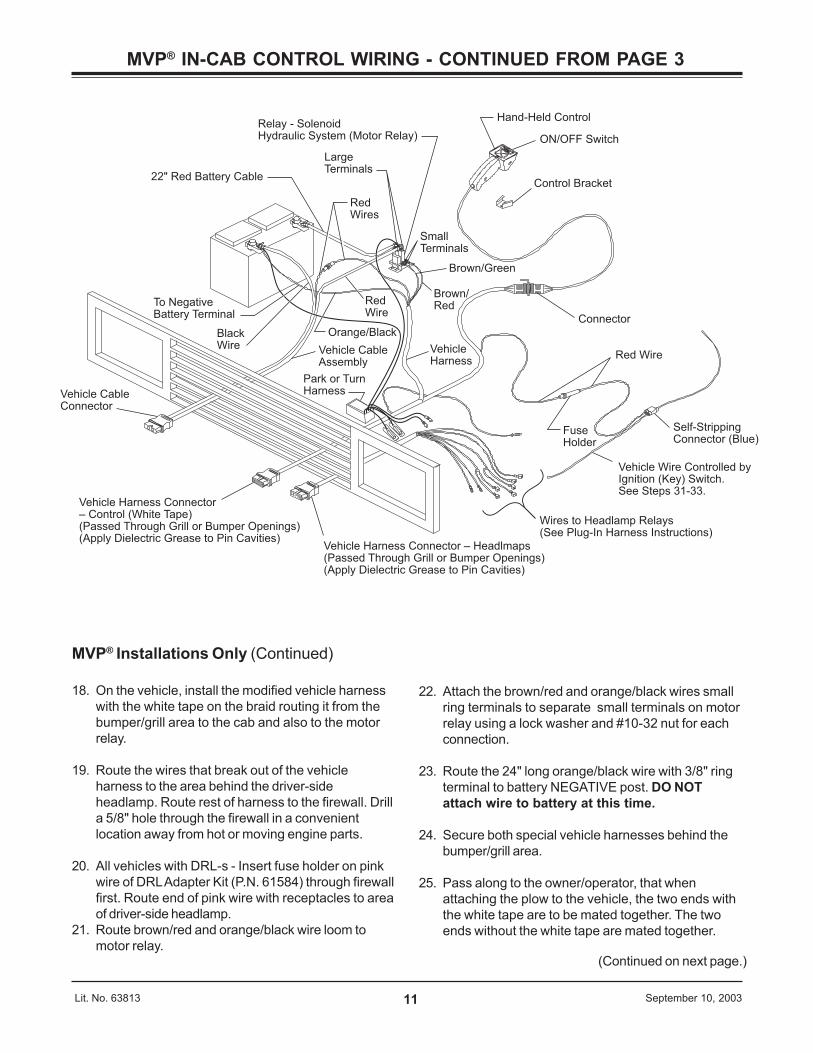
18. On the vehicle, install the modified vehicle harnesswith the white tape on the braid routing it from thebumper/grill area to the cab and also to the motorrelay.
19. Route the wires that break out of the vehicleharness to the area behind the driver-sideheadlamp. Route rest of harness to the firewall. Drilla 5/8" hole through the firewall in a convenientlocation away from hot or moving engine parts.
20. All vehicles with DRL-s - Insert fuse holder on pinkwire of DRL Adapter Kit (P.N. 61584) through firewallfirst. Route end of pink wire with receptacles to areaof driver-side headlamp.
21. Route brown/red and orange/black wire loom tomotor relay.
22. Attach the brown/red and orange/black wires smallring terminals to separate small terminals on motorrelay using a lock washer and #10-32 nut for eachconnection.
23. Route the 24" long orange/black wire with 3/8" ringterminal to battery NEGATIVE post. DO NOTattach wire to battery at this time.
24. Secure both special vehicle harnesses behind thebumper/grill area.
25. Pass along to the owner/operator, that whenattaching the plow to the vehicle, the two ends withthe white tape are to be mated together. The twoends without the white tape are mated together.
(Continued on next page.)
12Lit. No. 63813 September 10, 2003
MVP® IN-CAB CONTROL WIRING - CONTINUED FROM PAGE 3
MVP® Installations Only (Continued)
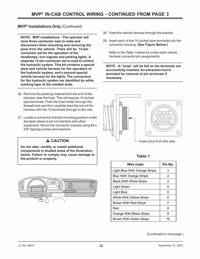
NOTE: MVP installations - The operator willhave three connector sets to mate anddisconnect when mounting and removing theplow from the vehicle. There will be 12-pinconnector set for the operation of theheadlamps, turn signals and parking lights. Aseparate 12-pin connector set is used to controlthe hydraulic system. This kit contains a specialplow and vehicle harness for the operation ofthe hydraulic system, and a second specialvehicle harness for the lights. The connectorsfor the hydraulic system are identified by whitemarking tape at the molded ends.
26. Remove the packing material form the end of theharness near the fuse. This will expose 10 socket-type terminals. Push the fuse holder through thefirewall hole and then carefully feed the end of theharness with the 10 terminals through to the cab.
27. Locate a connector bracket mounting position underthe dash where it will not interfere with otherequipment. Mount the connector bracket using #3 x5/8" tapping screws and washers.
CAUTIONDo not alter, modify, or install additionalcomponents in shaded areas of the illustrationbelow. Failure to comply may cause damage tothe product or property.
(Continued on next page.)
28. Feed the vehicle harness through the bracket.
29. Insert each of the 10 socket-type terminals into theconnector housing. (See Figure Below.)
Refer to the Table 1 below for under-dash vehicleharness connector pin assignments.
NOTE: A “snap” will be felt as the terminals aresuccessfully inserted. An extraction tool isprovided for removal of pin terminals ifnecessary.
Wire Color Pin No.
Light Blue With Orange Stripe 1 Blue With Orange Stripe 2 Black With White Stripe 3 Light Green 4 Light Blue 5 White With Yellow Stripe 6 Brown With Red Stripe 7 Red 8 Orange With Black Stripe 9 Brown With Green Stripe 10
Table 1
Insert pins from this side
13Lit. No. 63813 September 10, 2003
MVP® IN-CAB CONTROL WIRING - CONTINUED FROM PAGE 3
MVP® Installations Only (Continued)
30. Secure the connector to the bracket with theprovided #6-32 x 1/4" tapping screws and lockwashers.
31. Remove the knee panel below the steering column.Next, remove the bezel (heater control and mappocket are part of the bezel) from around the radioand air vents by removing the screw in the lowerright corner. Gently pull out on the hook below thescrew to release the spring clips that retain thebezel. There are two spring clips at the top (eitherside of the radio), two spring clips in the middle(either side of the heater control) and six clips alongthe bottom. Hold down the release tabs to removethe four connectors from the back of the bezel foreasy access to the cigar lighter wires.
32. Route the plow vehicle harness red wire with fuseholder to the opening with the cigar lighter wires init. Route carefully to avoid sharp edges which cancut the wire insulation. Leave enough wire so thefuse holder can be serviced from the opening underthe steering column. Trim excess red wire and jointhe plow vehicle harness fuse holder red wire to thered wire for the cigar lighter.
33. Open the blue, self-stripping connector and placethe end of the red wire against the inner groove stop(end of wire must not extend from the connectorwhen it is closed) and the accessory wire in theouter groove. Close the connector over the wiresusing a pliers and snap the locking tab into place.
Operating the plow control may require up to 10 amps ofcurrent. Using the plow control, while the cigar lighter orother large power consumer plugged into the lighteropening is in use, may “blow” the fuse due to the largecurrent draw. Replace a blown fuse with the same sizefuse (cigar lighter circuit is 20 amps). Installing anoversized fuse may allow the wires to overheat resultingin a damaged vehicle wiring harness.
34. Install grommet around the harness at the firewallhole if drilled. Install second grommet if hole wasdrilled in radiator bulk head. Cable tie harness asrequired.
35. Under hood near motor relay, connect the femalespade terminal on the small red wire from thevehicle cable to the male spade terminal on the redwire from the vehicle harness.
36. Reconnect the vehicle battery POSITIVE (+) andNEGATIVE (-) cables.
37. Go to Page 6-9 (without or with DRL’s) and followthe diagram for connections to the headlamp relaysand turn signal relays.
14Lit. N
o. 63813Septem
ber 10, 2003
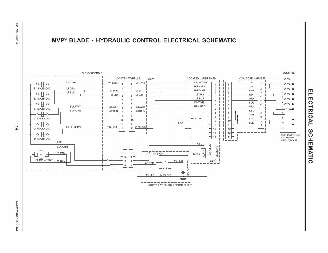
MVP® BLADE - HYDRAULIC CONTROL ELECTRICAL SCHEMATIC
*
CIRCUIT BOARD
OF PRINTED
REPRESENTATION
11
*
8
10
9
7
6
4
5
3
CONTROL
1
2
ORN
11
10
9
7
8
5
6
TAN
BLK
BRN
GRN
RED
BLU
COIL CORD HARNESS
4
3
1
2
WHT
GRY
YEL
VIO
13
14
OR
N/B
LK
RED
14
13
12
V B
AT
TE
RY
LOCATED AT VEHICLE FRONT RIGHT
#6 RED
MTR RLY
10AFB
LOCATED UNDER DASH
BLU/ORN
LT BLU/ORN
BLK/WHT
LT BLU
LT GRN
BRN/RED
WHT/YEL
11
12
9
10
7
8
5
6
3
4
2
1
12
11
10
9
7
8
5
6
3
4
2
1
RED
BRN/GRN
BRN
#6 BLK
#6 RED
FASTON
LOCATED AT GRILLE WHT
PUMP MOTOR
#6 RED
#6 BLK
+M-
RED
BLK/ORN
S6 SOLENOID
LT BLU/ORN
BLU/ORN
BLK/WHT
WHT/YEL
LT BLU
LT GRN
IGN
ITIO
N
1
8
12
11
9
10
4
6
7
5
2
3
8
12
11
9
10
4
6
7
5
2
3
1
4
2
3
11
2
3
4
S5 SOLENOID
S4 SOLENOID
S3 SOLENOID
S2 SOLENOID
S1 SOLENOID
PLOW ASSEMBLY
WHT/YEL
LT GRN
LT BLU
BLK/WHT
BLU/ORN
LT BLU/ORN
WHT/YEL
LT GRN
LT BLU
BLK/WHT
BLU/ORN
LT BLU/ORN
ELECTR
ICA
L SCH
EMATIC
15Lit. No. 63813 September 10, 2003
12-PIN HEADLAMP KIT MODIFICATION
61550-1 HEADLAMP KIT 12-PIN64078 HEADLAMP KIT 12-PIN (WHITE)
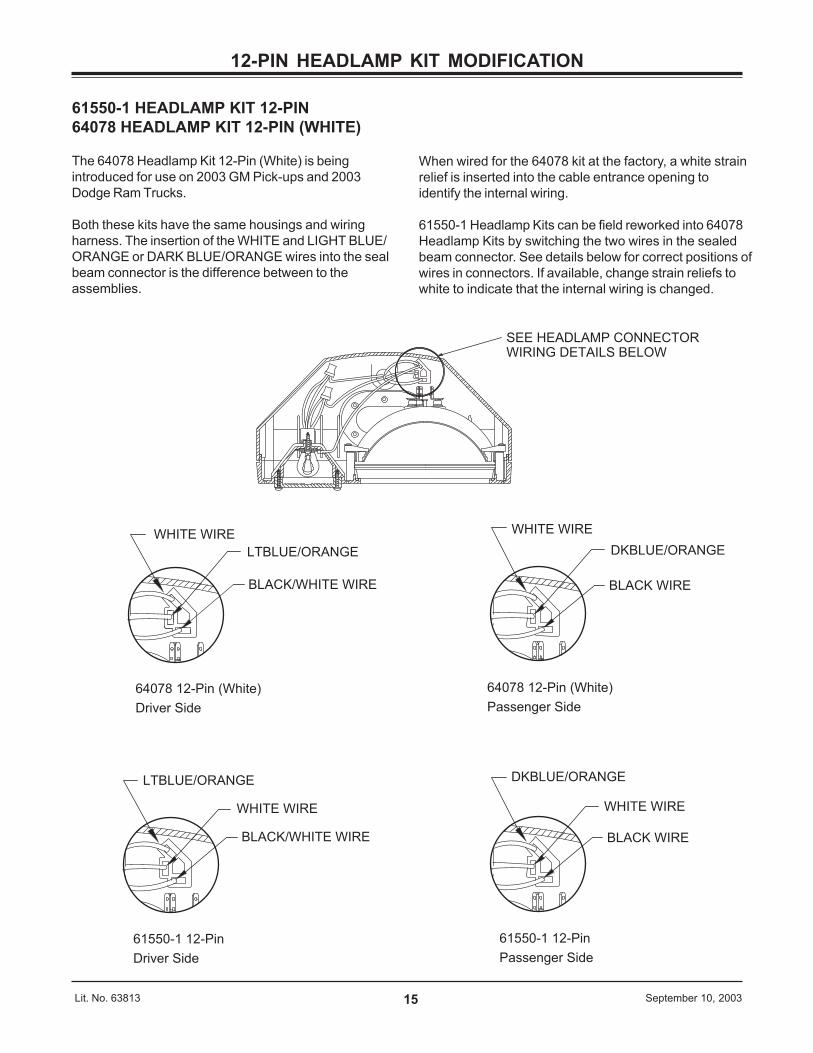
The 64078 Headlamp Kit 12-Pin (White) is beingintroduced for use on 2003 GM Pick-ups and 2003Dodge Ram Trucks.
Both these kits have the same housings and wiringharness. The insertion of the WHITE and LIGHT BLUE/ORANGE or DARK BLUE/ORANGE wires into the sealbeam connector is the difference between to theassemblies.
When wired for the 64078 kit at the factory, a white strainrelief is inserted into the cable entrance opening toidentify the internal wiring.
61550-1 Headlamp Kits can be field reworked into 64078Headlamp Kits by switching the two wires in the sealedbeam connector. See details below for correct positions ofwires in connectors. If available, change strain reliefs towhite to indicate that the internal wiring is changed.
LTBLUE/ORANGE
WHITE WIRE
BLACK/WHITE WIRE
DKBLUE/ORANGE
BLACK WIRE
WHITE WIRE
DKBLUE/ORANGE
BLACK WIRE
WHITE WIRE
LTBLUE/ORANGE
BLACK/WHITE WIRE
WHITE WIRE
SEE HEADLAMP CONNECTOR WIRING DETAILS BELOW
61550-1 12-Pin
Driver Side
61550-1 12-Pin
Passenger Side
64078 12-Pin (White)
Driver Side
64078 12-Pin (White)
Passenger Side
16Lit. No. 63813 September 10, 2003
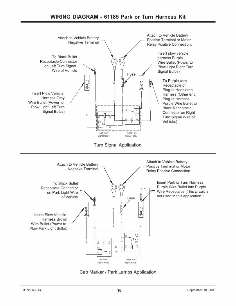
WIRING DIAGRAM - 61185 Park or Turn Harness Kit
Attach to Vehicle Battery
Negative Terminal
Insert Plow Vehicle
Harness Brown
Wire Bullet (Power to
Plow Park Light Bulbs)
To Black Bullet
Receptacle Connector
on Park Light Wire
of Vehicle
Cab Marker / Park Lamps Application
Right Turn
Signal Relay
87
87a
Signal Relay
86
87
87a
GY
GY
Left Turn
R
BK
85
30
BK
RR
R
86
R
30
85
BK
Insert Park or Turn Harness
Purple Wire Bullet into Purple
Wire Receptalce (This circuit is
not used in this application.)
PU
PU
Attach to Vehicle Battery
Positive Terminal or Motor
Relay Positive Connection.
PU
Left Turn
Signal Relay
87a
87
86
30
85
GY
GY
87a
87
86
30
85
PU
BK
BK
R
R
RR
R
BK
PU
To Purple wire
Receptacle on
Plug-In Headlamp
Harness (Other end
Plug-In Harness
Purple Wire Bullet to
Black Receptacle
Connector on Right
Turn Signal Wire of
Vehicle.)
Insert plow vehicle
harness Purple
Wire Bullet (Power to
Plow Light Right Turn
Signal Bulbs)
Attach to Vehicle Battery
Positive Terminal or Motor
Relay Positive Connection.
Attach to Vehicle Battery
Negative Terminal
Insert Plow Vehicle
Harness Gray
Wire Bullet (Power to
Plow Light Left Turn
Signal Bulbs)
To Black Bullet
Receptacle Connector
on Left Turn Signal
Wire of Vehicle
Right Turn
Signal Relay
Turn Signal Application
Fuse
Fuse

A DIVISION OF DOUGLAS DYNAMICS, L.L.C.
WESTERN PRODUCTSP.O. BOX 245038MILWAUKEE, WI 53224-9538
Lit. No. 63813 September 10, 2003Printed in U.S.A.
Western Products reserves the right under its product improvement policy to change construction or design details and furnish equipmentwhen so altered without reference to illustrations or specifications used. Western Products and the vehicle manufacturer may require and/or recommend optional equipment for snow removal. Do not exceed vehicle ratings with a snowplow. Western Products offers a limitedwarranty for all snowplows and accessories. See separately printed page for this important information. The following are registered (®)trademarks of Douglas Dynamics, L.L.C.: UltraMount® and WESTERN®.