1+apps.sd.gov/HC65C2C/EBS/lettings/electronicplans/047D_NonSection.pdf · table for pcc pavement...
36
NH 0081(98)35 1 36 5
Transcript of 1+apps.sd.gov/HC65C2C/EBS/lettings/electronicplans/047D_NonSection.pdf · table for pcc pavement...

NH 0081(98)35 1 36
5

PROJECT
STATE OF
SOUTH DAKOTA __ ____(__)___
SHEET
10 __
TOTAL SHEETS
SPECIFICATIONS Standard Specifications for Roads and Bridges, 2004 Edition and Required Provisions, Supplemental Specifications and/or Special Provisions as included in the Proposal.
NH 0081(98)35 2 36

NH 0081(98)35 3 36

TABLE FOR PCC PAVEMENT REPAIR INSERT STEEL BAR IN PCC PAVEMENT 1" x 18" SEAL
PLAIN RANDOM NB DRIVING SB PASSING NEW ROUND No. 8 x 18" No. 5 x 24" TIE BAR TYPE A REPAIR CRACKS
LANE LANE JOINT DOWEL DEFORMED DEFORMED DOWEL RETROFIT SPALL TYPE A IN PCC L W L W PCCP CON- BARS TIE BARS TIE BARS BAR STITCHING SIZE SPALL PAVEMENT
MRM LANE Ft Ft Ft Ft SqYds FIG. Each Each Each Each Each L W SqFt Ft COMMENTS - Miscellaneous35.284 Both 3035.389 NB 6 6 4.0 R 8 2 635.445 SB 36'' 12'' 3.0035.445 SB 18'' 6'' 0.7535.445 NB 12'' 6'' 0.5035.471 NB 18'' 6'' 0.7535.489 NB 10'' 10'' 0.6935.527 NB 6'' 6'' 0.2535.543 SB 6 6 4.0 R 8 4 635.572 NB 10'' 18'' 1.2535.586 NB 8'' 12'' 0.6735.694 NB 12'' 12'' 1.0035.759 SB 535.802 SB 18'' 9'' 1.1335.813 SB 12'' 12'' 1.0035.838 SB 18'' 6'' 0.7536.136 SB 12'' 6'' 0.5036.181 SB 18'' 9'' 1.1336.218 SB 6'' 12'' 0.5036.241 SB 6'' 12'' 0.5036.526 Both 6 14 6 14 18.7 R 32 2 2436.577 SB 12'' 6'' 0.5037.129 SB 7'' 12'' 0.5837.728 SB 12'' 18'' 1.5037.741 NB 18'' 18'' 2.2537.741 SB 12'' 18'' 1.5037.775 SB 6'' 12'' 0.5037.788 Both 6 14 9 14 23.3 R 32 3 2437.795 Both 6 14 6 14 18.7 R 32 2 2437.801 SB 6'' 36'' 1.5037.839 SB 6'' 12'' 0.5037.843 SB 6'' 12'' 0.5037.870 SB 12'' 12'' 1.0037.870 NB 6'' 18'' 0.7537.916 Both 2937.942 NB 7'' 12'' 0.5837.953 NB 12'' 12'' 1.0037.953 SB 9'' 18'' 1.1337.972 NB 6 6 4.0 R 8 2 637.987 SB 9'' 24'' 1.5037.998 NB 9'' 12'' 0.7538.021 SB 12'' 24'' 2.0038.036 SB 6 14 9.3 R 16 2 1238.047 SB 10'' 18'' 1.2538.089 SB 12'' 18'' 1.5038.112 SB 9'' 24'' 1.5038.119 NB 6 6 4.0 R 8 2 6 12'' 24'' 2.0038.130 Both 6 14 6 6 13.3 R 24 4 1838.134 NB 12'' 24'' 2.0038.144 SB 12'' 12'' 1.0038.144 NB 7'' 12'' 0.5838.155 Both 3038.170 SB 6 6 4.0 R 8 4 638.178 NB 6 6 4.0 R 8 2 638.219 SB 6 6 4.0 R 8 4 6 18 3638.277 SB 12'' 24'' 2.00
PROJECT
STATE OF
SOUTH DAKOTA __ ____(__)___
SHEET
10 __
TOTAL SHEETS
NH 0081(98)35 4 36

TABLE FOR PCC PAVEMENT REPAIR INSERT STEEL BAR IN PCC PAVEMENT 1" x 18" SEAL
PLAIN RANDOM NB DRIVING SB PASSING NEW ROUND No. 8 x 18" No. 5 x 24" TIE BAR TYPE A REPAIR CRACKS
LANE LANE JOINT DOWEL DEFORMED DEFORMED DOWEL RETROFIT SPALL TYPE A IN PCC L W L W PCCP CON- BARS TIE BARS TIE BARS BAR STITCHING SIZE SPALL PAVEMENT
MRM LANE Ft Ft Ft Ft SqYds FIG. Each Each Each Each Each L W SqFt Ft COMMENTS - Miscellaneous38.277 NB 12'' 24'' 2.0038.339 Both 6 6 4.0 R 8 4 6 12'' 12'' 1.0038.350 SB 12'' 12'' 1.0038.467 NB 10'' 24'' 1.6738.492 SB 12'' 24'' 2.0038.593 NB 6 6 4.0 R 8 2 6 6'' 12'' 0.5038.601 SB 6'' 18'' 0.7538.632 Both 2838.669 SB 12'' 12'' 1.0038.876 SB 12'' 12'' 1.0038.929 SB 12'' 24'' 2.0039.013 Both 2839.016 Both 2839.020 Both 3139.078 SB 9'' 18'' 1.1339.120 NB 6 6 4.0 R 8 2 639.477 SB 6 6 4.0 R 8 4 639.578 NB 7'' 18'' 0.8840.299 SB 12'' 18'' 1.5040.350 SB 6'' 18'' 0.7540.639 Both 12'' 18'' 1.5040.662 SB 12'' 12'' 1.0040.814 NB 12'' 18'' 1.5040.943 NB 9'' 18'' 1.1341.092 NB 12'' 18'' 1.5041.095 NB 9'' 9'' 0.5641.666 SB 12'' 12'' 1.0042.394 Both 2943.030 SB 12'' 12'' 1.0043.148 SB 24'' 24'' 4.0043.508 SB 6'' 24'' 1.0043.619 Both 30 14 30 14 93.3 R 32 12 2444.053 Both 2844.056 Both 2844.484 Both 6 14 6 14 18.7 R 32 2 2444.739 NB 6 6 4.0 R 8 2 645.246 SB 12'' 12'' 1.0045.265 SB 6'' 18'' 0.7545.265 SB 12'' 12'' 1.0045.510 SB 4045.545 SB 1445.548 NB 1545.555 Both 1445.560 NB 24 14 21.8 16 16 9 12 Railroad - Triangle - Needs rebar mat46.111 SB 9'' 12'' 0.7546.161 SB 7'' 36'' 1.7546.263 NB 6'' 18'' 0.7546.263 SB 12'' 12'' 1.0046.506 Both 17.5 14 17.5 14 54.4 R 32 7 2446.749 NB 7'' 18'' 0.8846.899 NB 12'' 12'' 1.0046.910 NB 12'' 18'' 1.5046.918 NB 18'' 18'' 2.2547.529 NB 12'' 12'' 1.0047.677 SB 12'' 12'' 1.0047.810 NB 12'' 12'' 1.00
PROJECT
STATE OF
SOUTH DAKOTA __ ____(__)___
SHEET
10 __
TOTAL SHEETS
NH 0081(98)35 5 36

TABLE FOR PCC PAVEMENT REPAIR INSERT STEEL BAR IN PCC PAVEMENT 1" x 18" SEAL
PLAIN RANDOM NB DRIVING SB PASSING NEW ROUND No. 8 x 18" No. 5 x 24" TIE BAR TYPE A REPAIR CRACKS
LANE LANE JOINT DOWEL DEFORMED DEFORMED DOWEL RETROFIT SPALL TYPE A IN PCC L W L W PCCP CON- BARS TIE BARS TIE BARS BAR STITCHING SIZE SPALL PAVEMENT
MRM LANE Ft Ft Ft Ft SqYds FIG. Each Each Each Each Each L W SqFt Ft COMMENTS - Miscellaneous48.106 NB 12'' 12'' 1.0048.583 SB 12'' 18'' 1.5048.840 NB 12'' 18'' 1.5049.226 NB 6'' 24'' 1.0049.245 SB 6 14 9.3 R 16 2 1249.252 SB 6'' 36'' 1.5049.270 Both 1449.285 Both 6 14 9.3 R 16 2 12 3049.293 SB 6 14 9.3 R 16 2 1249.301 SB 12'' 24'' 2.0049.307 Both 6 14 9.3 R 16 2 12 6'' 24'' 1.0049.320 NB 6'' 36'' 1.5049.332 SB 8 14 12.4 R 16 3 1249.391 Both 12 14 12 14 37.3 B 16 16 449.396 Both 10 14 10 14 31.1 B 16 16 449.492 NB 12'' 12'' 1.0049.793 SB 6'' 12'' 0.5049.815 NB 12'' 24'' 2.0049.854 NB 12'' 12'' 1.0049.906 NB 12'' 12'' 1.0049.924 NB 12'' 12'' 1.0049.973 NB 12'' 12'' 1.0049.991 NB 12'' 12'' 1.0049.995 SB 12'' 12'' 1.0050.780 NB 12'' 36'' 3.0050.780 SB 12'' 12'' 1.0050.983 NB 12'' 18'' 1.5051.015 Both 12 14 12 14 37.3 B 16 16 451.055 NB 12'' 24'' 2.0051.093 NB 12'' 12'' 1.0051.226 NB 12'' 18'' 1.5051.226 SB 12'' 12'' 1.0051.351 SB 8 14 12.4 B 8 8 351.430 SB 12'' 12'' 1.0051.464 NB 6'' 12'' 0.5051.464 SB 18'' 18'' 2.2551.604 SB 20 8 17.8 W 10 1651.641 NB 6'' 36'' 1.5051.645 SB 6'' 24'' 1.0051.671 NB 6'' 36'' 1.5051.683 NB 6'' 48'' 2.0051.699 NB 12'' 18'' 1.5051.887 SB 12'' 18'' 1.5051.996 NB 20 14 31.1 W 16 852.184 NB 6'' 18'' 0.7552.374 NB 16 14 24.9 B 8 8 652.398 Both 10 14 10 14 31.1 B 16 16 452.595 NB 12'' 12'' 1.0052.595 SB 12'' 12'' 1.0052.613 NB 12'' 18'' 1.5052.964 SB 18'' 18'' 2.2553.072 NB 18'' 30'' 3.7553.108 NB 12'' 12'' 1.0053.186 SB 12'' 24'' 2.0053.311 NB 10 14 15.6 B 8 8 453.364 SB 6 14 9.3 R 16 2 12
PROJECT
STATE OF
SOUTH DAKOTA __ ____(__)___
SHEET
10 __
TOTAL SHEETS
NH 0081(98)35 6 36

TABLE FOR PCC PAVEMENT REPAIR INSERT STEEL BAR IN PCC PAVEMENT 1" x 18" SEAL
PLAIN RANDOM NB DRIVING SB PASSING NEW ROUND No. 8 x 18" No. 5 x 24" TIE BAR TYPE A REPAIR CRACKS
LANE LANE JOINT DOWEL DEFORMED DEFORMED DOWEL RETROFIT SPALL TYPE A IN PCC L W L W PCCP CON- BARS TIE BARS TIE BARS BAR STITCHING SIZE SPALL PAVEMENT
MRM LANE Ft Ft Ft Ft SqYds FIG. Each Each Each Each Each L W SqFt Ft COMMENTS - Miscellaneous53.896 NB 6 6 4.0 R 8 2 653.928 SB 12'' 12'' 1.0054.023 SB 6'' 6'' 0.2554.065 Both 6 14 6 14 18.7 W 32 254.114 Both 14 14 14 14 43.6 B 16 16 554.191 SB 12'' 12'' 1.0054.221 NB 18'' 12'' 1.5054.315 SB 10 14 15.6 W 16 454.356 SB 18'' 12'' 1.5054.401 NB 18'' 12'' 1.5054.498 SB 24'' 24'' 4.0054.513 SB 12'' 12'' 1.0054.517 SB 12'' 12'' 1.0054.551 NB 6'' 6'' 0.2554.597 NB 12'' 48'' 4.0054.631 NB 12'' 48'' 4.0054.649 Both 6 14 6 14 18.7 W 32 254.653 Both 6 14 6 14 18.7 W 32 254.657 Both 6 14 6 14 18.7 W 32 254.699 Both 14 14 14 14 43.6 W 32 554.746 NB 12'' 18'' 1.5054.880 SB 48'' 24'' 8.0054.945 NB 12'' 12'' 1.0054.945 SB 12'' 12'' 1.0054.980 SB 12'' 12'' 1.0055.074 SB 12'' 12'' 1.0055.112 Both 6 14 6 14 18.7 W 32 255.185 SB 12'' 12'' 1.0055.223 SB 6 14 9.3 R 16 2 1255.269 SB 36'' 12'' 3.0055.275 Both 6 14 6 14 18.7 W 32 255.356 NB 40 14 62.2 W 16 16 2455.358 SB 24'' 12'' 2.0055.382 SB 48'' 12'' 4.0055.399 Both 12 14 12 14 37.3 W 32 455.451 NB 12'' 12'' 1.0055.501 NB 12'' 12'' 1.0055.501 SB 12'' 12'' 1.0055.507 Both 6 14 6 14 18.7 W 32 255.619 NB 12'' 12'' 1.0055.619 SB 12'' 12'' 1.0055.681 SB 12'' 12'' 1.0055.685 NB 12'' 12'' 1.0055.685 NB 12'' 12'' 1.0055.733 Both 6 14 6 14 18.7 W 32 255.753 Both 6 14 6 14 18.7 W 32 255.756 NB 6 14 9.3 T 16 255.785 SB 6 14 9.3 W 16 255.816 SB 12'' 12'' 1.0055.828 NB 6 14 9.3 B 8 8 255.828 SB 18'' 18'' 2.2555.847 SB 12'' 12'' 1.0055.866 NB 24'' 12'' 2.0055.874 Both 6 14 6 14 18.7 W 32 255.974 NB 12'' 12'' 1.0055.974 NB 12'' 12'' 1.00
PROJECT
STATE OF
SOUTH DAKOTA __ ____(__)___
SHEET
10 __
TOTAL SHEETS
NH 0081(98)35 7 36

TABLE FOR PCC PAVEMENT REPAIR INSERT STEEL BAR IN PCC PAVEMENT 1" x 18" SEAL
PLAIN RANDOM NB DRIVING SB PASSING NEW ROUND No. 8 x 18" No. 5 x 24" TIE BAR TYPE A REPAIR CRACKS
LANE LANE JOINT DOWEL DEFORMED DEFORMED DOWEL RETROFIT SPALL TYPE A IN PCC L W L W PCCP CON- BARS TIE BARS TIE BARS BAR STITCHING SIZE SPALL PAVEMENT
MRM LANE Ft Ft Ft Ft SqYds FIG. Each Each Each Each Each L W SqFt Ft COMMENTS - Miscellaneous55.978 NB 12'' 12'' 1.0056.045 NB 24'' 12'' 2.0056.045 SB 12'' 12'' 1.0056.145 NB 12'' 24'' 2.0056.168 NB 18'' 36'' 4.5056.176 NB 12'' 12'' 1.0056.176 SB 12'' 12'' 1.0056.186 NB 12'' 12'' 1.0056.191 NB 12'' 12'' 1.0056.191 SB 12'' 24'' 2.0056.241 NB 12'' 12'' 1.0056.245 NB 12'' 24'' 2.0056.261 NB 6'' 60'' 2.5056.284 NB 12'' 72'' 6.0056.309 Both 20 14 20 14 62.2 W 32 856.334 NB 12'' 12'' 1.0056.354 NB 6'' 36'' 1.5056.354 SB 12'' 12'' 1.0056.365 NB 12'' 12'' 1.0056.365 NB 24'' 12'' 2.0056.373 SB 12'' 12'' 1.0056.388 NB 24'' 36'' 6.0056.388 SB 12'' 12'' 1.0056.402 Both 20 14 20 14 62.2 W 32 856.407 SB 12'' 12'' 1.0056.426 SB 12'' 18'' 1.5056.446 SB 12'' 12'' 1.0056.457 Both 22 14 34.2 W 16 8 12 12'' 12'' 1.0056.534 NB 6'' 12'' 0.5056.549 NB 12'' 12'' 1.0056.549 SB 6'' 12'' 0.5056.570 Both 10 14 10 14 31.1 B 16 16 456.641 NB 6'' 18'' 0.7556.721 NB 12'' 12'' 1.0056.721 SB 12'' 12'' 1.0056.737 NB 12'' 18'' 1.5056.763 NB 6 14 9.3 W 16 256.783 SB 6'' 12'' 0.5056.840 Both 6 6 4.0 B 4 4 2 12'' 12'' 1.0056.905 NB 12'' 12'' 1.0056.916 SB 12'' 30'' 2.5056.932 NB 6'' 6'' 0.2556.932 SB 12'' 12'' 1.0056.993 NB 12'' 12'' 1.0057.000 SB 6'' 18'' 0.7557.037 NB 6'' 12'' 0.5057.054 Both 10 14 10 14 31.1 W 32 457.184 SB 12'' 18'' 1.5057.214 SB 12'' 12'' 1.0057.264 NB 6'' 12'' 0.5057.290 SB 6'' 12'' 0.5057.359 SB 6'' 6'' 0.2557.359 SB 12'' 12'' 1.0057.390 NB 12'' 18'' 1.5057.390 SB 12'' 18'' 1.5057.413 NB 12'' 12'' 1.00
PROJECT
STATE OF
SOUTH DAKOTA __ ____(__)___
SHEET
10 __
TOTAL SHEETS
NH 0081(98)35 8 36

TABLE FOR PCC PAVEMENT REPAIR INSERT STEEL BAR IN PCC PAVEMENT 1" x 18" SEAL
PLAIN RANDOM NB DRIVING SB PASSING NEW ROUND No. 8 x 18" No. 5 x 24" TIE BAR TYPE A REPAIR CRACKS
LANE LANE JOINT DOWEL DEFORMED DEFORMED DOWEL RETROFIT SPALL TYPE A IN PCC L W L W PCCP CON- BARS TIE BARS TIE BARS BAR STITCHING SIZE SPALL PAVEMENT
MRM LANE Ft Ft Ft Ft SqYds FIG. Each Each Each Each Each L W SqFt Ft COMMENTS - Miscellaneous57.413 SB 24'' 18'' 3.0057.493 NB 20 14 31.1 W 16 857.496 Both 10 14 10 14 31.1 W 32 457.657 SB 6 14 9.3 R 16 2 1257.677 NB 12'' 24'' 2.0057.688 SB 6 14 9.3 B 8 8 257.750 NB 26 14 40.4 W 16 10 1257.765 SB 12'' 12'' 1.0057.777 NB 6'' 6'' 0.2557.846 Both 20 14 20 14 62.2 W 32 857.906 Both 20 14 20 14 62.2 W 32 857.972 NB 6 6 4.0 B 4 4 257.981 SB 48'' 12'' 4.0058.000 SB 6 14 9.3 B 8 8 258.021 SB 24'' 30'' 5.0058.055 SB 12'' 24'' 2.0058.082 NB 6 14 9.3 W 16 258.109 NB 6'' 12'' 0.5058.150 SB 100 14 155.6 W 16 40 6058.158 SB Shld 20 6 13.3 W 8 1658.165 SB Shld 20 6 13.3 W 8 1658.182 NB 12'' 42'' 3.5058.182 SB 12'' 12'' 1.0058.182 SB 12'' 48'' 4.0058.199 SB Shld 10 6 6.7 B 4 4 858.203 SB Shld 10 6 6.7 B 4 4 858.208 NB 6 8 5.3 R 10 2 858.320 SB 80 14 124.4 W 16 32 4858.377 NB 12'' 36'' 3.0058.377 SB 12'' 36'' 3.0058.383 Both 20 14 20 14 62.2 W 32 858.412 NB 6'' 18'' 0.7558.423 SB 6'' 12'' 0.5058.443 SB 6'' 12'' 0.5058.443 SB 6'' 24'' 1.0058.546 NB 100 14 155.6 W 16 40 6058.561 Both 40 14 40 14 124.4 W 32 16 4858.569 SB 120 14 186.7 W 16 48 7258.600 SB 6'' 12'' 0.5058.645 SB 12'' 12'' 1.0058.670 NB 140 14 217.8 W 16 56 8458.711 SB 12'' 18'' 1.5058.790 NB 6'' 18'' 0.7558.864 NB 40 14 62.2 W 16 16 2458.910 NB 12'' 18'' 1.5058.973 SB 6'' 30'' 1.2558.990 SB 6'' 30'' 1.2559.027 SB 6 8 5.3 R 10 4 859.102 NB 6'' 30'' 1.2559.124 NB 12'' 12'' 1.0059.124 SB 6'' 36'' 1.5059.130 SB 12'' 18'' 1.5059.196 NB 12'' 30'' 2.5059.214 Both 40 14 100 14 217.8 W 32 40 8459.244 SB 12'' 18'' 1.5059.266 NB 6 6 4.0 R 8 2 6
PROJECT
STATE OF
SOUTH DAKOTA __ ____(__)___
SHEET
10 __
TOTAL SHEETS
NH 0081(98)35 9 36

TABLE FOR PCC PAVEMENT REPAIR INSERT STEEL BAR IN PCC PAVEMENT 1" x 18" SEAL
PLAIN RANDOM NB DRIVING SB PASSING NEW ROUND No. 8 x 18" No. 5 x 24" TIE BAR TYPE A REPAIR CRACKS
LANE LANE JOINT DOWEL DEFORMED DEFORMED DOWEL RETROFIT SPALL TYPE A IN PCC L W L W PCCP CON- BARS TIE BARS TIE BARS BAR STITCHING SIZE SPALL PAVEMENT
MRM LANE Ft Ft Ft Ft SqYds FIG. Each Each Each Each Each L W SqFt Ft COMMENTS - Miscellaneous59.361 Both 6 14 6 14 18.7 W 32 259.379 NB 50 14 77.8 B 8 8 20 2459.393 NB 12'' 30'' 2.5059.393 SB 12'' 18'' 1.5059.407 NB 190 14 295.6 W 16 76 10859.421 SB 60 14 93.3 W 16 24 3659.446 SB 20 4059.456 NB 30 6059.460 SB 10 2059.486 SB 100 14 155.6 W 16 40 6059.493 NB 18'' 36'' 4.5059.523 SB 20 4059.590 NB 6'' 24'' 1.0059.590 SB 12'' 12'' 1.0059.602 SB 12'' 12'' 1.0059.612 NB 12'' 12'' 1.0059.612 NB 12'' 18'' 1.5059.635 Both 6 6 6 6 8.0 R 16 6 1259.667 SB 30 12'' 12'' 1.00 6059.716 NB 12'' 12'' 1.0059.716 NB 24'' 18'' 3.0059.716 SB 24'' 12'' 2.0059.730 Both 20 14 20 14 62.2 W 32 859.766 Both 7 14 7 14 21.8 W 32 260.004 SB 12'' 12'' 1.0060.104 NB 12'' 12'' 1.0060.104 SB 12'' 18'' 1.5060.195 SB 12'' 12'' 1.0060.265 Both 6 6 6 6 8.0 R 16 6 1260.323 SB 80 16060.337 NB 14 14 21.8 B 8 8 560.381 NB 12'' 12'' 1.0060.387 NB 18'' 12'' 1.5060.414 SB 12'' 12'' 1.0060.426 NB 24'' 12'' 2.0060.438 SB 40 8060.459 NB 30'' 18'' 3.7560.459 NB 6'' 48'' 2.0060.459 SB 18'' 18'' 2.2560.530 NB 12'' 12'' 1.0060.530 SB 12'' 12'' 1.0060.534 NB 18'' 18'' 2.2560.552 NB 12'' 18'' 1.5060.552 NB 12'' 36'' 3.0060.604 Both 14 14 14 14 43.6 W 32 560.624 SB 20 4060.648 SB 18'' 24'' 3.0060.662 SB 6'' 24'' 1.0060.679 NB 6'' 30'' 1.2560.698 SB 6'' 30'' 1.2560.713 NB 12'' 12'' 1.0060.718 SB 5 1060.805 NB 12'' 24'' 2.0060.836 NB 10 2060.840 Both 20 14 20 14 62.2 W 32 860.844 NB 10 20
PROJECT
STATE OF
SOUTH DAKOTA __ ____(__)___
SHEET
10 __
TOTAL SHEETS
NH 0081(98)35 10 36
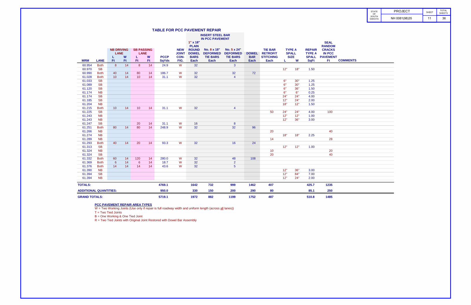
TABLE FOR PCC PAVEMENT REPAIR INSERT STEEL BAR IN PCC PAVEMENT 1" x 18" SEAL
PLAIN RANDOM NB DRIVING SB PASSING NEW ROUND No. 8 x 18" No. 5 x 24" TIE BAR TYPE A REPAIR CRACKS
LANE LANE JOINT DOWEL DEFORMED DEFORMED DOWEL RETROFIT SPALL TYPE A IN PCC L W L W PCCP CON- BARS TIE BARS TIE BARS BAR STITCHING SIZE SPALL PAVEMENT
MRM LANE Ft Ft Ft Ft SqYds FIG. Each Each Each Each Each L W SqFt Ft COMMENTS - Miscellaneous60.954 Both 8 14 8 14 24.9 W 32 360.970 SB 12'' 18'' 1.5060.990 Both 40 14 80 14 186.7 W 32 32 7261.028 Both 10 14 10 14 31.1 W 32 461.033 SB 6'' 30'' 1.2561.089 SB 6'' 30'' 1.2561.120 SB 6'' 36'' 1.5061.174 NB 6'' 6'' 0.2561.174 SB 24'' 24'' 4.0061.185 SB 12'' 24'' 2.0061.204 NB 18'' 12'' 1.5061.215 Both 10 14 10 14 31.1 W 32 461.225 SB 50 24'' 24'' 4.00 10061.243 NB 12'' 12'' 1.0061.243 NB 12'' 36'' 3.0061.247 SB 20 14 31.1 W 16 861.251 Both 80 14 80 14 248.9 W 32 32 9661.266 NB 20 4061.274 NB 18'' 18'' 2.2561.289 NB 14 2861.293 Both 40 14 20 14 93.3 W 32 16 2461.313 SB 12'' 12'' 1.0061.324 NB 10 2061.324 SB 20 4061.332 Both 60 14 120 14 280.0 W 32 48 10861.369 Both 6 14 6 14 18.7 W 32 261.376 Both 14 14 14 14 43.6 W 32 561.390 NB 12'' 36'' 3.0061.394 SB 12'' 84'' 7.0061.394 NB 12'' 24'' 2.00
TOTALS: 1599 1038 1598 998 4769.1 1 1642 732 999 1462 407 3492 5161 425.7 1235 1 1
ADDITIONAL QUANTITIES: 950.0 330 150 200 290 80 85.1 250
GRAND TOTALS: 5719.1 1972 882 1199 1752 487 510.8 1485
PCC PAVEMENT REPAIR AREA TYPESW = Two Working Joints (Use only if repair is full roadway width and uniform length (across all lanes))T = Two Tied JointsB = One Working & One Tied JointR = Two Tied Joints with Original Joint Restored with Dowel Bar Assembly
PROJECT
STATE OF
SOUTH DAKOTA __ ____(__)___
SHEET
10 __
TOTAL SHEETS
NH 0081(98)35 11 36

TABLE FOR PCC PAVEMENT REPAIR AT INTERSECTING ROADS INSERT STEEL BAR IN PCC PAVEMENT
1" x 18" SEAL PLAIN RANDOM
EB WB NEW ROUND No. 8 x 18" No. 5 x 24" TYPE A REPAIR CRACKSLANE LANE JOINT DOWEL DEFORMED DEFORMED DOWEL SPALL TYPE A IN PCC
L W L W PCCP CON- BARS TIE BARS TIE BARS BAR SIZE SPALL PAVEMENTJUNCT SIDE Ft Ft Ft Ft SqYds FIG. Each Each Each Each L W SqFt Ft COMMENTS - Miscellaneous
SD 42 E Leg 12'' 12'' 1.00 56SD 42 W Leg 56SD 44 E Leg 12'' 12'' 1.00 56SD 44 W Leg 12'' 24'' 2.00 42SD 44 W Leg 12'' 12'' 1.00SD 44 W Leg 12'' 18'' 1.50Canistota W Leg 8 14 8 14 24.9 W 32 3I90 EB On 6 6 4.0 B 4 4 2I90 EB On 8 14 8 14 24.9 W 32 3I90 EB Off 8 14 8 14 24.9 W 32 3I90 WB Off 10 14 10 14 31.1 W 32 4I90 WB On 12 14 12 14 37.3 W 32 4 14Salem E Leg 28 14 28 14 87.1 R 32 11 24Salem W Leg 6'' 30'' 1.25Salem W Leg 12'' 24'' 2.00Salem W Leg 6'' 12'' 0.50
TOTALS: 80 90 74 84 234.2 1 164 36 30 24 84 144 10.3 224 1 1
ADDITIONAL QUANTITIES: 50.0 30 10 10 0 2.1 40
GRAND TOTALS: 284.2 194 46 40 24 12.4 264
PCC PAVEMENT REPAIR AREA TYPESW = Two Working Joints (Use only if repair is full roadway width and uniform length (across all lanes))T = Two Tied JointsB = One Working & One Tied JointR = Two Tied Joints with Original Joint Restored with Dowel Bar Assembly
PROJECT
STATE OF
SOUTH DAKOTA __ ____(__)___
SHEET
10 __
TOTAL SHEETS
NH 0081(98)35 12 36

MRM to MRM LOCATION LENGTH
TOP
WIDTH
BOTTOM
WIDTH
COLD MILLING
ASPHALT CONCRETE
(3" DEPTH)
CLASS HR
ASPHALT
CONCRETE PG 58‐28
MC 70
PRIME
SS‐1h
TACK
SS‐1h
FLUSH
SHOULDER
PREPARATION
FT FT FT SqYd TON TON TON TON TON MI
49.24 to 51.36 NB Shoulder 11194 6.5 8 9950 1501 60.1 12.7 0.1 2.1 2.1
49.24 to 51.30 SB Shoulder 10877 6.5 8 9668 1459 58.4 12.3 0.1 2.1 2.1
56.72 to 57.76 NB Shoulder 5491 6.5 8 4881 737 29.5 6.2 0.0 1.0 1.0
57.30 to 57.76 SB Shoulder 2429 6.5 8 2159 326 13.0 2.8 0.0 0.5 0.5
57.97 to 58.15 NB Shoulder 950 6.5 8 845 127 5.1 1.1 0.0 0.2 0.2
58.21 to 61.56 NB Shoulder 17688 6.5 8 15723 2372 94.9 20.0 0.1 3.3 3.4
57.97 to 61.56 SB Shoulder 18955 6.5 8 16849 2542 101.7 21.5 0.1 3.6 3.6
TOTALS 60075 9065 362.6 76.6 0.4 12.8 12.8
63078 9518 380.7 80.4 0.4 13.4 13.4
These quantities and locations are estimates only.
Final locations and dimensions shall be marked by the Engineer and are subject to change.
PG 58‐28 Binder calculated at 4.0% of the total mix
MC 70 for Prime, Rate = 0.30 gallons/square yard
SS‐1h or CSS‐1h for Tack, Rate = 0.05 gallons/square yard
SS‐1h or CSS‐1h for Flush, Rate = 0.05 gallons/square yard
Quantities increased 5%
TABLE FOR AC SHOULDER REPAIR
PROJECT
STATE OF
SOUTH DAKOTA __ ____(__)___
SHEET
10 __
TOTAL SHEETS
NH 0081(98)35 13 36

PROJECT
STATE OF
SOUTH DAKOTA __ ____(__)___
SHEET
10 __
TOTAL SHEETS
UTILITIES The Contractor shall contact the involved utility companies through South Dakota One Call (1-800-781-7474) prior to starting work. It shall be the responsibility of the Contractor to coordinate work with the utility owners to avoid damage to existing facilities. Utilities are not planned to be affected on this project. If utilities are identified near the improvement area through the SD One Call Process as required by South Dakota Codified Law 49-7A and Administrative Rule Article 20:25, the Contractor shall contact the Project Engineer to determine modifications that will be necessary to avoid utility impacts. SCOPE OF WORK This project consists of crack sealing, tie bar retrofit (stitching), spall repair, and full depth replacement of concrete pavement in areas where concrete pavement blowups or major failures have occurred, as well as cold milling and asphalt paving on the shoulders. Full depth areas vary in length and width; however the minimum size is 6 feet square. Spall repairs will be a minimum of 6 inches square. All existing transverse joints shall be sawed and sealed. In addition, all joints at repair areas shall be sawed and sealed. COORDINATION BETWEEN CONTRACTORS A separate contract for Project 081-292, PCN I3AJ will be awarded to another Contractor for shoulder repair on US Highway 81 from MRM 35.20 to MRM 49.30. The Contractor shall schedule his work so as not to interfere with or hinder the progress of the work performed by other Contractors on the shoulder repair project. RAILROAD CROSSING The Contractor is to coordinate work with the Railroad Company regarding any work to be done adjacent to the railroad tracks and give 30 days notice to the Railroad Company in advance of required flagging dates. See Special Provision for Working on Railroad Company Right of Way. TYPE II FIELD LABORATORY The lab shall be equipped with an internet connection such as DSL, cable modem, or other approved service. The internet connection shall be provided with a multi-port wireless router. The internet connection shall be a minimum speed of 512 Kb unless limited by job location and approved by the DOT. Prior to installing the wireless router the Contractor shall submit the wireless router’s technical data to the Area Office to check for compatibility with the state’s computer equipment. The internet connection is intended for state personnel usage only. The Contractor’s personnel are prohibited from using the internet connection unless pre-approved by the Project Engineer. The Contractor shall submit a copy of each monthly bill for calls charged to this phone at the end of each month. The Project Engineer will then audit the bills to ensure all calls are legitimate and then initiate a Construction Change Order (CCO) to reimburse the Contractor for the actual phone calls made, including local and long distance calls. Reimbursement will not be made for fees associated with the purchase, installation, disconnection, monthly line charges, and incidentals involved in the installation, maintenance, and disconnection of the phone (including attachments). These items shall be incidental to the contract unit price per each for “Type II Field Laboratory”.
ENVIRONMENTAL COMMITMENTS An Environmental Commitment is a measure that SDDOT commits to implement in order to avoid, minimize, and/or mitigate a real or potential environmental impact. Environmental commitments to various agencies and the public have been made to secure approval of this project. An agency mentioned below with permitting authority can influence a project if perceived environmental impacts have not been adequately addressed. Unless otherwise designated, the Contractor’s primary contact regarding matters associated with these commitments will be the Project Engineer. These environmental commitments are not subject to change without prior written approval from the SDDOT Environmental Office. The environmental commitments associated with this project are as follows: FEDERALLY THREATENED, ENDANGERED & PROTECTED SPECIES COMMITMENT B2: WHOOPING CRANE The Whooping Crane is a spring and fall migratory bird in South Dakota that is about 5 feet tall and typically stops on wetlands, rivers, and agricultural lands along their migration route. An adult Whooping Crane is white with a red crown and a long, dark, pointed bill. Immature Whooping Cranes are cinnamon brown. While in flight, their long necks are kept straight and their long dark legs trail behind. Adult Whooping Cranes' black wing tips are visible during flight. Action Taken/Required: Harassment or other measures to cause the Whooping Crane to leave the site is a violation of the Endangered Species Act. If a Whooping Crane is sighted roosting in the vicinity of the project, borrow pit, or staging site associated with the project, cease construction activities in the affected area until the Whooping Crane departs and contact the Project Engineer. The Project Engineer will contact the Environmental Office so that the sighting can be reported to USFWS. COMMITMENT H: WASTE DISPOSAL SITE The Contractor shall furnish a site(s) for the disposal of construction and/or demolition debris generated by this project. Action Taken/Required: Construction and/or demolition debris may not be disposed of within the State ROW. The waste disposal site(s) shall be managed and reclaimed in accordance with the following from the General Permit for Highway, Road, and Railway Construction/Demolition Debris Disposal Under the South Dakota Waste Management Program issued by the Department of Environment and Natural Resources. The waste disposal site(s) shall not be located in a wetland, within 200 feet of surface water, or in an area that adversely affects wildlife, recreation, aesthetic value of an area, or any threatened or endangered species, as approved by the Project Engineer. If the waste disposal site(s) is located such that it is within view of any ROW, the following additional requirements shall apply:
COMMITMENT H: WASTE DISPOSAL SITE (Continued) 1. Construction and/or demolition debris consisting of concrete, asphalt concrete, or other similar materials shall be buried in a trench completely separate from wood debris. The final cover over the construction and/or demolition debris shall consist of a minimum of 1 foot of soil capable of supporting vegetation. Waste disposal sites provided outside of the State ROW shall be seeded in accordance with Natural Resources Conservation Service recommendations. The seeding recommendations may be obtained through the appropriate County NRCS Office. The Contractor shall control the access to waste disposal sites not within the State ROW through the use of fences, gates, and placement of a sign or signs at the entrance to the site stating “No Dumping Allowed”. 2. Concrete and asphalt concrete debris may be stockpiled within view of the ROW for a period of time not to exceed the duration of the project. Prior to project completion, the waste shall be removed from view of the ROW or buried and the waste disposal site reclaimed as noted above. The above requirements will not apply to waste disposal sites that are covered by an individual solid waste permit as specified in SDCL 34A-6-58, SDCL 34A-6-1.13, and ARSD 74:27:10:06. Failure to comply with the requirements stated above may result in civil penalties in accordance with South Dakota Solid Waste Law, SDCL 34A-6-1.31. All costs associated with furnishing waste disposal site(s), disposing of waste, maintaining control of access (fence, gates, and signs), and reclamation of the waste disposal site(s) shall be incidental to the various contract items. COMMITMENT I: HISTORICAL PRESERVATION OFFICE CLEARANCES The SDDOT has obtained concurrence with the State Historical Preservation Office (SHPO or THPO) for all work included within the project limits and all designated option borrow sites provided within the plans. Action Taken/Required: All earth disturbing activities not designated within the plans require review of cultural resources impacts. This work includes, but is not limited to: staging areas, borrow sites, waste disposal sites, and all material processing sites. The Contractor shall arrange and pay for a cultural resource survey and/or records search. The Contractor has the option to contact the state Archaeological Research Center (ARC) at 605-394-1936 or another qualified archaeologist, to obtain either a records search or a cultural resources survey. A record search might be sufficient for review; however, a cultural resources survey may need to be conducted by a qualified archaeologist. The Contractor shall provide ARC with the following: a topographical map or aerial view on which the site is clearly outlined, site dimensions, project number, and PCN. If applicable, provide evidence that the site has been previously disturbed by farming, mining, or construction activities with a landowner statement that artifacts have not been found on the site.
NH 0081(98)35 14 36

PROJECT
STATE OF
SOUTH DAKOTA __ ____(__)___
SHEET
11 __
TOTAL SHEETS
COMMITMENT I: HISTORICAL PRESERVATION OFFICE CLEARANCES (Continued) The Contractor shall submit the records search or cultural resources survey report and if the location of the site is within the current geographical or historic boundaries of any South Dakota reservation to SDDOT Environmental Engineer, 700 East Broadway Avenue, Pierre, SD 57501-2586 (605-773-3180). SDDOT will submit the information to the appropriate SHPO/THPO. Allow 30 Days from the date this information is submitted to the Environmental Engineer for SHPO/THPO review. If evidence for cultural resources is uncovered during project construction activities, then such activities shall cease and the Project Engineer shall be immediately notified. The Project Engineer will contact the SDDOT Environmental Engineer in order to determine an appropriate course of action. SHPO/THPO review does not relieve the Contractor of the responsibility for obtaining any additional permits and clearances for staging areas, borrow sites, waste disposal sites, or material processing sites that affect wetlands, threatened and endangered species, or waterways. The Contractor shall provide the required permits and clearances to the Project Engineer at the preconstruction meeting. EXISTING PCC PAVEMENT The existing pavement is 8” x 28’ Nonreinforced PCC Pavement. Existing contraction joints are spaced at approximately 20’. Longitudinal joints are reinforced with No. 5 x 30” deformed tie bars spaced 48” center to center. Transverse joints are reinforced with 1¼” x 18” plain round dowel bars spaced 12” center to center. The aggregate in the existing PCC Pavement is quartzite. RESTORATION OF GRAVEL CUSHION An inspection of the gravel cushion subgrade shall be made after removing concrete from each pavement replacement area. Areas of excess moisture shall be dried to the satisfaction of the Engineer. Loose material shall be removed. Each replacement area shall be leveled and compacted to the satisfaction of the Engineer. If additional gravel cushion material is required, the Contractor shall haul, place and compact gravel cushion to the satisfaction of the Engineer at no additional cost to the State. Additional gravel cushion (blended asphalt and gravel stockpile) can be obtained from the Department of Transportation Maintenance shop located in Salem and may be used without further testing. Cost for this work shall be incidental to the contract unit price per square yard for Nonreinforced PCC Pavement Repair. NONREINFORCED PCC PAVEMENT REPAIR - GENERAL Locations and size (length or width) of concrete repair areas are subject to change in the field, at the discretion of the Engineer, at no additional cost to the state. Payment will be based on actual area replaced. Existing concrete pavement shall be sawed full depth at the beginning and end of the PCCP repair areas. When either the beginning or end of a PCCP repair area falls close to an existing joint or crack, the PCCP repair area shall be extended to eliminate the existing joint or crack. Where possible, new working joints shall be adjacent to existing working joints.
NONREINFORCED PCC PAVEMENT REPAIR – GENERAL (Continued) Saw cuts that extend beyond the repair area shall be minimized and filled with a non-shrinkage mortar mix at the Contractor’s expense. Existing concrete pavement in the replacement areas shall be removed by the lift out method or by means that minimize damage to the base and sides of remaining in place concrete. All removed material shall be removed from within the right-of-way by the end of the workday. Damage to adjacent concrete caused by the Contractor’s operations shall be removed and replaced at the Contractor’s expense. If the pavement replacement area is entirely on either side of the existing contraction joint, the location of one of the working joints will be at the original location. Any existing dowel bar assemblies/steel bars shall be sawed off and removed. At full roadway width repairs and when specified, a working joint will be reconstructed at both ends of each pavement replacement area as shown in these plans. Concrete placed adjacent to asphalt concrete shoulders shall be formed full depth to match the width of existing concrete pavement. Asphalt concrete shoulders adjacent to concrete pavement replacements shall be repaired with new hot-mix asphalt concrete. At repair locations where the new working joint is not opposite the existing working joint, the Contractor shall place a ¼” preformed asphalt expansion joint material along the longitudinal joint from the existing working joint to the new working joint. The expansion joint material shall meet the requirements of AASHTO M33. Cost for this material shall be incidental to the contract unit price per square yard for Nonreinforced PCC Pavement Repair. All joints (longitudinal and transverse) through and around the repair areas will be sawed and sealed in accordance with the details shown in these plans. Refer to Saw and Seal Joints notes. NONREINFORCED PCC PAVEMENT REPAIR New pavement thickness shall be 9”, which is equal to existing pavement thickness + 1” (TN = T+1”). Concrete shall meet the requirements of the Standard Specifications Section 380, except as modified by the following notes:
The fine aggregate shall be screened over a one-inch square-opening screen just prior to introduction into the concrete paving mix if required by the Engineer. The slump requirement will be limited to 3" maximum after water reducer is added and the concrete shall contain 4.5% to 7.0% entrained air. The concrete shall contain a minimum of 50% coarse aggregate by weight. Coarse aggregate shall be crushed ledge rock, Size No. 1 unless an alternative gradation is approved by the Concrete Engineer as part of the mix design submittal. The mix design shall contain at least 650 lbs of Type I or II cement or 600 lbs of Type III cement per cubic yard. The minimum 28 day compressive strength shall be 4,000 psi. The Contractor is responsible for the mix design used. The Contractor shall submit a mix design and supporting documentation for approval at least 2 weeks prior to use. The use of a water reducer at manufacturer's recommended dosage will be required.
NONREINFORCED PCC PAVEMENT REPAIR (Continued)
Concrete shall be cured with white pigmented curing compound (AASHTO M148, Type 2) applied as soon as practical at a rate of 125 square feet per gallon. Concrete shall be cured for a minimum of 24 hours before opening to traffic. The 24 hours is based upon a concrete surface temperature of 60º F or higher throughout the cure period. If the concrete temperature falls below 60º F, the cure time shall be extended or other measures shall be taken, at no additional cost to the State. In addition to the curing time requirements, a strength of 3,800 psi must be attained prior to opening to traffic. For purposes of traffic control quantity estimation, cure time needed to obtain 3,800 psi has been estimated at 48 hours. An initial cylinder shall be made and the Engineer shall calibrate a Swiss Hammer to it. All subsequent strength tests shall be by Swiss Hammer. Cylinders will be made according to Materials Manual requirements and the Swiss Hammer calibration regularly updated according to the early break cylinders. The Engineer will test the repair areas after an initial 24 hour cure period by Swiss Hammer. No section is to be opened to traffic without the permission of the Engineer. If the concrete does not achieve 3,800 psi by 48 hours after placement, the Contractor shall provide required traffic control (at no cost to the State) until the Engineer determines the 3,800 psi has been obtained. No additional work zones will be set up until strength requirement is met.
Upon placement of the concrete, repair areas shall be straight edged to ensure a smooth riding surface and shall be textured longitudinally with the pavement by finishing with a stiff broom. Repair areas shall then be checked with a 10’ foot straight edge. The permissible longitudinal and transverse surface deviation shall be 1/8” in 10’. Concrete shall be covered with suitable insulation blanket consisting of a layer of closed cell polystyrene foam protected by at least one layer of plastic. Insulation blanket shall have an R-value of at least 0.5, as rated by the manufacturer. Insulation blanket shall be left in place, except for joint sawing operations, until the 3,800 psi is attained. Insulation blanket shall be overlapped on to the existing concrete by 4’. The initial contraction joint sawing shall be performed as soon as practical after placement to avoid random cracking. This requirement for covering repair areas with insulation blankets may be waived during periods of hot weather upon approval of the Engineer. Cost for performing the aforementioned work including sawing and removing concrete, furnishing and placing concrete, sawing and sealing longitudinal joints, repairing asphalt concrete shoulders, labor, tools and equipment shall be included in the contract unit price per square yard for Nonreinforced PCC Pavement Repair. FULL DEPTH REPAIR – MRM 45.560 NB The full depth repair area at this location shall be reinforced with No. 5 reinforcing steel as detailed in these plans. The exact size of the repair area will be determined by the Engineer upon construction. All costs to furnish and install the No. 5 reinforcing steel will be incidental to the contract unit price per square yard for Nonreinforced PCC Pavement Repair.
NH 0081(98)35 15 36

PROJECT
STATE OF
SOUTH DAKOTA __ ____(__)___
SHEET
12 __
TOTAL SHEETS
FORMED RUMBLE STRIP IN PCCP If 2 or more consecutive rumble strips are removed, all shall be replaced in that repair location as detailed in these plans, except that the spacing shall be 60’ to match the existing rumble strips. New formed rumble strips shall be in the original locations. Cost for Formed Rumble Strip in PCCP shall be incidental to the contract unit price for Nonreinforced PCC Pavement repair. STEEL BAR INSERTION Locations and quantities of concrete repair are subject to change in the field at the discretion of the Engineer. The Contractor will be responsible for ordering the actual quantity of steel bars necessary to complete the work. The Contractor shall insert the steel bars (1" x 18" epoxy coated plain round dowel bars and No. 8 x 18" epoxy coated deformed tie bars for transverse joints and No. 5 x 24” epoxy coated deformed tie bars for longitudinal joints) into drilled holes in the existing concrete pavement. An epoxy resin adhesive must be used to anchor the steel bar in the drilled hole. Plain round dowel bars shall be cut to the specified length by sawing and shall be free from burring or other deformations. Shearing will not be permitted. Epoxy resin adhesive shall be of the type intended for horizontal applications, and shall conform to the requirements of ASTM C 881, Type IV, Grade 3 (equivalent to AASHTO M235, Type IV, Grade 3). Steel bars shall be inserted in the transverse joint on 18" centers. The first steel bar in the transverse joint shall be placed 9" from the edge of the slab closest to centerline. No transverse bars are to be used in the outer 2’ of concrete beyond the 12’ lane. Steel bars shall be inserted in the longitudinal joint on 30" centers and shall be a minimum of 15" from either transverse joint. A typical one-lane patch 14' wide and 6’ long will require 18 steel bars (8 in each transverse joint and 2 in the longitudinal joint). It will be necessary to laterally adjust the location of some of the inserted steel bars when the dimensions above interfere with existing steel bar locations. The diameter of the drilled holes in the existing concrete pavement for the steel bars shall not be less than 1/8 inch nor more than 3/8 inch greater than the overall diameter of the steel bar. Holes drilled into the existing concrete pavement shall be located at mid-depth of the slab and true and normal. The drilled holes shall be blown out with compressed air using a device that will reach to the back of the hole to ensure that all debris or loose material has been removed prior to epoxy injection. A rigid frame or mechanical device will be required to guide the drill to ensure proper horizontal and vertical alignment of the steel bars in the drilled holes. Mix the epoxy resin as recommended by the manufacturer and apply by an injection method approved by the Engineer. If an epoxy pump is utilized, it shall be capable of metering the components at the manufacturer’s designated rate and be equipped with an automatic shut-off. The pump shall shut off when any of the components are not being metered at the designated rate. Fill the drilled holes 1/3 to 1/2 full of epoxy, or as recommended by the manufacturer, prior to insertion of the steel bar. Care shall be taken to prevent epoxy from running out of the horizontal holes prior to steel bar insertion. Rotate the steel bar during insertion to eliminate voids and ensure complete bonding of the bar. Insertion by the dipping method will not be allowed. The epoxy shall start to gel before placing fresh concrete or as per manufacturer’s recommendations if given.
STEEL BAR INSERTION (Continued) Cost for the epoxy resin adhesive, steel bars, drilling of holes, inserting the steel bars into the drilled holes and all other items incidental to the insertion of the steel bars shall be included in the contract unit price per each for Insert Steel Bar in PCC Pavement. SAW AND SEAL JOINTS for Nonreinforced PCCP Repair All longitudinal and transverse joints at concrete repair areas shall be sawed and sealed. Joints shall not be sealed unless they are thoroughly clean and dry. Cleaning shall be accomplished by sand blasting and other tools as necessary. Just prior to sealing, each joint shall be blown out using a jet of compressed air to remove all traces of dust. Transverse joints shall be sealed with Low Modulus Silicone Sealant. Longitudinal joints may be sealed with either Hot Poured Elastic Joint Sealer or Low Modulus Silicone Sealant. Cost for sawing and sealing of the longitudinal construction joint(s) and transverse joint(s) at the repair areas shall be incidental to the contract unit price per square yard for Nonreinforced PCC Pavement Repair. RESEAL PCC PAVEMENT JOINT Existing transverse joints shall be cleaned and resealed with Low Modulus Silicone Sealant. Joints shall not be sealed unless they are thoroughly clean and dry to the satisfaction of the Engineer. Removal of existing sealant shall be accomplished by sawing, cutting, sandblasting and/or other tools as necessary. Sand blasting of both sides of the vessel shall be accomplished simultaneously with a mechanical device approved by the Engineer after the majority of the sealant is removed. Just prior to sealing, each joint shall be blown out using a jet of compressed air to remove all traces of dust. In certain areas the joint may be wider than the original construction. It may be necessary to provide backer rod in the wide areas. Any additional cost to perform this work shall be at no additional cost to the State. The Contractor shall be responsible to verify joint widths prior to establishing the contract unit price. It is not essential that all of the sealant be removed. Remaining sealant adhering to the sides may remain in place if the Engineer determines that it is not detrimental to the joint. Cost for cleaning and resealing transverse joints shall be included in the contract unit price per foot for Reseal PCC Pavement Joint – Silicone. REPAIR TYPE A SPALLS The Contractor shall saw an area a minimum of 6” x 6” and remove the material to a minimum depth of 1½” until sound concrete is found. After sawing the Contractor shall remove the vertical edge by chipping with a jackhammer not to exceed 15 lbs. Alternatively, the Contractor may remove concrete by milling, provided it produces results similar to the sawing and chipping process described above. Spall repair locations will be marked in the field by the Engineer. Spall locations not large enough to be repaired will be marked for resealing.
REPAIR TYPE A SPALLS (Continued) Type A Spalls shall conform to Section 390 with the following exceptions:
The concrete patching material used for spall repair shall be a bagged MNDOT 3U18 patching material. The product shall be submitted and be approved by the Concrete Engineer. A product known to meet this requirement is Spec Mix/TCC Materials “Air Entrained Concrete Patching Mix”. Grout for bonding the concrete patching material to the existing concrete shall consist of two parts by weight of Portland Cement and one part sand, mixed with sufficient water to form a creamy slurry. Grout shall be applied on all of the existing concrete surfaces within the removal area immediately prior to placement of the concrete patching material. The grout shall be scrubbed into the surface with a stiff bristle brush in a thin and uniform coat. Care shall be taken to ensure that excess grout does not collect in low areas, that the grout is confined only to the immediate area in which concrete patching material is to be placed, and that the rate of application is limited to an amount such that the grout will be covered with concrete patching material before the grout dries.
The concrete patching material shall be mixed and placed in accordance with the manufacturer’s technical data sheet. The Contractor shall provide a manufacturer’s technical data sheet to the Engineer prior to performing the work. The concrete patching material shall be maintained at or above 45°F (7°C) for at least 72 hours after placement. Patched areas shall be sprayed with curing compound as per Section 390. An additional coat of curing compound shall be applied not less than 20 minutes and not more than 1 hour after the first application. Repair areas can be opened to traffic once the repair material meets 3,000 psi as long as the above requirement for temperature can be met. An initial cylinder shall be made and the Engineer shall calibrate a Swiss Hammer to it. All subsequent strength tests shall be by Swiss Hammer. Cylinders will be made according to Materials Manual requirements and the Swiss Hammer calibration regularly updated according to the early break cylinders. The Engineer will test the repair areas after an initial cure period by Swiss Hammer. If the area does not meet strength after the initial cure period, the area will be tested every 2-4 hours until nightfall, then not again until 7:00am. No section is to be opened to traffic without the permission of the Engineer.
If the Patch Material does not achieve 3,000 psi by 7 a.m. the day after placement, the Contractor shall provide required traffic control (at no cost to the State) until the Engineer determines the 3,000 psi has been obtained. No additional work zones will be set up until strength requirement is met. If strength requirement has not been met by 36 hours after placement, the patches shall be removed and replaced at no cost to the State.
Material used to form the joint shall be a foam core board or other stiff material capable of standing without deflection. The Contractor shall fill the area (with the foam core board or other approved material in place) with an approved patching material. The patching material shall be vibrated with a small hand held vibrator capable of thoroughly consolidating the patching compound into the area. The top surface of the filled area shall be trowel finished and cured.
NH 0081(98)35 16 36

PROJECT
STATE OF
SOUTH DAKOTA __ ____(__)___
SHEET
13 __
TOTAL SHEETS
REPAIR TYPE A SPALLS (Continued) After screeding and finishing, the same bonding grout shall be used to paint the edges of the repair. Any saw cuts that extend beyond the patch perimeter shall be filled with patching material and must also have the surface painted with bonding grout. After removal of the form material, the repaired length of the joint(s) shall be sealed. Cost for removing the form material and sealing the joint(s) shall be incidental to the contract unit price per square foot for Repair Type A Spall. Spalls which are repaired according to plans and specifications and exhibit partial respalling or cracking, shall be repaired to the satisfaction of the Engineer at no additional cost to the Department of Transportation. TIE BAR RETROFIT, STITCHING Tie Bar Retrofit, Stitching shall be done on longitudinal joints and random cracks as marked out by the Engineer. The Contractor shall insert No. 5 epoxy coated deformed tie bars into drilled holes in the existing concrete pavement. An epoxy resin adhesive must be used to anchor the steel bar in the drilled hole. A rotary drill or other approved drill shall be used that will not damage the concrete surface. The diameter of the disturbed surface from drilling shall be less than 2 inches. A rigid frame or mechanical device will be required to guide the drill to ensure the proper angle of the steel bars in the drilled holes. Epoxy resin adhesive shall be of the type intended for horizontal applications, and shall conform to the requirements of ASTM C 881, Type IV, Grade 3 (equivalent to AASHTO M235, Type IV, Grade 3). The dried color of the epoxy shall be gray or black. The diameter of the drilled holes in the existing concrete pavement for the steel bars shall not be less than 1/8 inch nor more than 3/8 inch greater than the overall diameter of the steel bar. The holes shall be drilled at an angle alternating from opposite sides of the joint to produce a cross-stitching pattern. The drilled holes shall be blown out with compressed air using a device that will reach to the back of the hole to ensure that all debris or loose material has been removed prior to epoxy injection. Damage to pavement shall be repaired to the satisfaction of the Engineer at the Contractor’s expense. Mix the epoxy resin as recommended by the manufacturer and apply by an injection method approved by the Engineer. If an epoxy pump is utilized, it shall be capable of metering the components at the manufacturer’s designated rate and be equipped with an automatic shut-off. The pump shall shut-off when any of the components are not being metered at the designated rate. Fill the drilled holes sufficiently with epoxy prior to the insertion of the tie bar such that the epoxy will be level with the top of the concrete pavement after insertion of the tie bar. Rotate the steel bar during insertion to eliminate voids and ensure complete bonding of the bar. Insertion of the bars by the dipping method will not be allowed. The top of the drilled hole shall be filled with epoxy or excess epoxy removed such that the epoxy is level with the existing pavement. No bars shall be inserted within 15” of an existing transverse contraction joint. Any bars not functioning or damaged shall be repaired or replaced at the Contractor’s expense. Cost for the epoxy resin adhesive, tie bars, drilling of holes, debris or loose material removal, applying the adhesive, inserting the tie bars into the drilled holes and incidentals necessary for the insertion of the tie bars shall be included in the contract unit price per each for Tie Bar Retrofit, Stitching.
SEAL RANDOM CRACKS IN PCC PAVEMENT Random cracks shall be repaired in accordance with the detail for Sealing Random Cracks. Reservoir dimensions may vary slightly from the details, due to the nature of this operation. However, any variance due to Contractor negligence will be repaired at the Contractor’s expense. Only those random cracks in the existing concrete pavement that are open and accept water and incompressible materials as selected by the Engineer shall be prepared and sealed with either Low Modulus Silicone Sealant or Hot Poured Elastic Joint Sealer. Prior to sealing, each random crack shall be routed and thoroughly cleaned with compressed air or by other methods satisfactory to the Engineer. Routing shall be performed with a saw designed for that purpose. Random cracks narrower than ½ inch shall be routed and sealed ½ inch wide by ½ inch deep. Random cracks wider than ½ inch may require the placement of a backer rod prior to sealing. Sealant shall be placed in the routed reservoir with equipment and by methods that insure complete and uniform filling. Hot Poured Elastic Joint Sealer shall be placed level with the driving surface of the concrete. Low Modulus Silicone Sealant shall have a tooled surface with the top middle portion of the sealant recessed. Any excess or overrun of sealant shall be removed by the Contractor at no additional cost to the state. Seal Random Cracks in PCC Pavement will be measured by the foot to the nearest 0.1 foot of random cracks sealed and accepted on the project, and will be paid for at the contract unit price per foot measured for payment. Payment shall be full compensation for all labor, equipment, material and incidentals required for crack routing, cleaning, furnishing and installing backer rod when necessary, furnishing and placing sealant and removing routed and foreign material from the roadway.
SEALING RANDOM CRACKS UNCLASSIFIED EXCAVATION-DIGOUTS Included in the Estimate of Quantities are 400 cubic yards of Unclassified Excavation-Digouts for repairing any base material issues that may become apparent during repairs of the PCCP roadway or AC shoulders. Locations and dimensions shall be determined in the field by the Engineer.
UNCLASSIFIED EXCAVATION-DIGOUTS (Continued) Cost for removal, hauling, and disposal of existing base material shall be included in the contract unit price per cubic yard for Unclassified Excavation-Digouts. BASE COURSE, SALVAGED ASPHALT MIX Backfill for digouts under the Asphalt shoulders, estimated at 400 tons, shall be obtained from Cold Milling Asphalt Concrete operation and may be used without further testing. Shoulder backfill shall be compacted according to Section 260.3.B of the Standard Specifications except that a pneumatic tired roller will be required. If necessary, water shall be added to the backfill material to bring it to ±6% of optimum moisture content at the time of compaction. Compaction shall be to the satisfaction of the Engineer. Cost for material, hauling, placing, watering, and compacting backfill shall be included in the contract unit price per cubic yard for Base Course, Salvaged Asphalt Mix. BASE COURSE, SALVAGED, STATE FURNISHED Backfill for digouts under the PCCP roadway, estimated at 400 tons, shall be blended asphalt and gravel obtained from the Department of Transportation Maintenance shop located in Salem and may be used without further testing. The material is provided royalty free to the Contractor. Furnish cost to the State for Base Course, Salvaged, State Furnished is $11.00 per ton. If necessary, water shall be added to the backfill material to bring it to ±6% of optimum moisture content at the time of compaction. Compaction shall be to the satisfaction of the Engineer. Cost for material, hauling, placing, watering, and compacting backfill shall be included in the contract unit price per cubic yard for Base Course, Salvaged, State Furnished. REPAIR OF ASPHALT CONCRETE SHOULDERS Cost for asphalt concrete required on the shoulder adjacent to full depth pavement replacement sections that are not in areas not designated for shoulder replacement shall be incidental to the contract unit price per square yard for Nonreinforced PCC Pavement Repair. SURFACING THICKNESS DIMENSIONS Plans tonnage or quantities will be applied even though the thickness may vary from that shown on the plans. At those locations where material must be placed to achieve a required elevation, plans tonnage or quantities may be varied to achieve the required elevation. SHOULDER WORK Prior to construction, Department of Transportation Maintenance Forces will spray the shoulders to kill existing vegetation. It is the Contractor’s responsibility to notify the State a minimum of 30 days prior to starting work on the surface of the highway. The State assumes no responsibility for the effectiveness of the herbicide applied.
Low Modulus Silicone Sealant
Existing Pavement
or
1/2”
1/2” min. 1/2” min.
Hot Poured Elastic Joint Sealer
1/2”
Rev 4-2-14 TH NH 0081(98)35 17 36

PROJECT
STATE OF
SOUTH DAKOTA __ ____(__)___
SHEET
14 __
TOTAL SHEETS
SHOULDER WORK (Continued) Vegetation and accumulated material on or adjacent to the existing roadway edge shall be removed to the satisfaction of the Engineer prior to asphalt concrete resurfacing. Any remaining windrow of accumulated material shall be spread evenly on the inslope adjacent to the asphalt shoulder, to the satisfaction of the Engineer, prior to the application of the flush seal. Shoulder work shall be incidental to other contract items. Separate measurement and payment will not be made. COLD MILLING ASPHALT CONCRETE The Contractor shall cold mill areas where the asphalt shoulders are damaged as directed by the Engineer. The depth of cold milling shall be 3 inches and the entire width of the asphalt shoulder. Cold milling is estimated to produce 10000 tons of salvaged asphalt concrete material. An estimated 2855 tons of salvaged asphalt concrete will be used in the Class HR Asphalt Concrete mixture. An estimated 400 tons of salvaged asphalt concrete will be used to backfill digouts in the asphalt shoulder. Estimated quantities are for information purposes only and the exact quantity will be determined upon construction. No allowance will be made for loss of expected reimbursement of loss of anticipated profit. The Los Angeles Abrasion Loss value on the aggregate used for the in place asphalt concrete varied from 25 to 35 percent. These values were obtained from testing during construction of the in place asphalt concrete. Cold Milling Asphalt Concrete operations ahead of asphalt concrete laydown will be limited by particular job conditions and will be subject to approval of the Engineer. In no case shall cold milling operations ahead of asphalt concrete laydown operations exceed seven calendar days. The Contractor shall ensure a reasonably smooth transition from all side roads, homes, and businesses to the driving lanes using material obtained from the cold milling process from the time the shoulder is milled until it is paved with hot mix asphalt. The cost of this work shall be incidental to the contract unit price per square yard for Cold Milling Asphalt Concrete. Milled material not reused on the project shall become property of the Contractor for disposal. Cold Milling Asphalt Concrete will be paid for at the contract unit price per square yard measured for payment. Payment shall be full compensation for all labor, equipment, and incidentals required for the cold milling operation. SHOULDER PREPARATION Prior to placement of asphalt concrete on the shoulders the existing base shall be bladed, watered, and compacted until a uniform, stable surface is obtained. Material obtained from Cold Milling Asphalt Concrete operations may be used on the shoulders as needed. Cost for this work shall be incidental to the contract unit price per mile for Shoulder Preparation. Compaction shall be to the satisfaction of the Engineer. Water needed for compaction shall be incidental to the contract unit price per mile for Shoulder Preparation. SAWING IN EXISTING SURFACING Where new asphalt concrete is placed adjacent to existing asphalt concrete or concrete pavement, the existing asphalt concrete or concrete pavement shall be sawed full depth to a true line with a vertical face. No separate payment will be made for sawing.
CLASS HR ASPHALT CONCRETE Virgin mineral aggregate for Class HR Asphalt Concrete shall conform to the requirements for Class E, Type 1. Virgin mineral aggregate shall be furnished by the Contractor. Salvaged asphalt concrete material (RAP) shall be obtained from the cold milled material produced on this project. The RAP shall be crushed to provide a homogeneous mixture of material so that the maximum particle size in the cold feed will not exceed 1 ½ inches (37.5 mm). Screening or scalping of the RAP stockpile(s) will not be allowed. The Class HR Asphalt Concrete shall include 30% RAP in the mixture. Job mix formula tolerances for the RAP shall be ±5% from the target value. All other requirements for Class HR shall apply. Asphalt shall be placed in one 3” (compacted) lift. Slope may need to be adjusted to match the existing shoulder slope. The estimated quantities are approximate and there will be no increase in the contract unit price per ton for Class HR Asphalt Concrete for any increases or decreases in either the haul or quantity. SAW AND SEAL SHOULDER JOINT After completion of the asphalt shoulder paving, the Contractor shall saw and seal the joint between the concrete pavement and the asphalt shoulder over the length of replaced shoulder. Saw and Seal Shoulder Joint will be paid at the contract unit price per foot measured for payment. Payment shall be full compensation for all materials, equipment, labor, and incidentals to the sawing and sealing operation. FLUSH SEAL Application of the flush seal shall be completed within 10 working days following completion of the asphalt concrete resurfacing. WORK ADJACENT TO EXISTING GUARDRAIL Beam type guardrail exists along the shoulders of the project. The Contractor shall conduct operations so as not to disturb the existing guardrail. Any guardrail disturbed / damaged due to the Contractor’s operations shall be replaced by the Contractor at no expense to the State. TEMPORARY PAVEMENT MARKING Temporary pavement marking on lane closure tapers shall consist of Temporary Road Markers. (Estimate four workspaces x 1,125’ tapers on I90 ramps = 4,500’). Temporary pavement marking on centerline shall consist of Temporary Road Markers and shall be used as depicted on Standard Plate 634.25 when the stop condition must remain in place during nighttime hours 9:00PM to 6:00AM (Estimate five workspaces remaining during nighttime hours x 2,200’ per workspace = 11,000’). Temporary Road Markers shall be removed when no longer needed. Removal can be accomplished by any method that fully removes the marker and does not damage the pavement. The Contractor shall be responsible for collection and disposal of removed markers. Cost for removal and disposal of Temporary Road Markers shall be incidental to the contract unit price per foot for Temporary Road Markers.
TEMPORARY PAVEMENT MARKING (Continued) Temporary pavement marking for stop bars shall consist of 4” Temporary Pavement Marking Tape Type 2. Placement of each 24” white stop bar shall be accomplished by placing six pieces of 4” x 12’ tape adjacent to one another. Each workspace requires two stop bars which is an equivalent of approximately 144’ of 4” tape (five workspaces at 144’ = 720’). Tape shall be removed when no longer needed. Removal can be accomplished by any method that fully removes the tape and does not damage the pavement. The Contractor shall be responsible for disposal of removed tape. Cost for removal and disposal of Temporary Pavement Marking Tape shall be incidental to the contract unit price per foot for 4” Temporary Pavement Marking Tape Type 2. GENERAL MAINTENANCE OF TRAFFIC Removing, relocating, covering, salvaging and resetting of permanent traffic control devices, including delineation, shall be the responsibility of the Contractor. Cost for this work shall be incidental to the contract unit prices for the various items unless otherwise specified in the plans. Any delineators and signs damaged or lost shall be replaced by the Contractor at no cost to the State. Storage of vehicles and equipment shall be outside the clear zone and as near as possible to the right-of-way line. Contractor’s employees should mobilize at a location off the right-of-way and arrive at the work sites in a minimum number of vehicles necessary to perform the work. Indiscriminate driving and parking of vehicles within the right-of-way will not be permitted. Any damage to the vegetation, surfacing, embankment, delineators and existing signs resulting from such indiscriminate use shall be repaired and/or restored by the Contractor, at no expense to the State, and to the satisfaction of the Engineer. The Contractor shall provide documentation that all breakaway sign supports comply with FHWA NCHRP 350 or MASH crash-worthy requirements. The Contractor shall provide installation details at the preconstruction meeting for all breakaway sign support assemblies. Sufficient traffic control devices have been included in these plans to sign three flagger controlled workspaces and one stop sign controlled workspace. If the Contractor elects to work on additional stop sign controlled workspaces simultaneously, the cost for additional traffic control devices shall be incidental to the contract unit price per unit for Traffic Control. However, there shall be no more than three flagger controlled workspaces at any time. MAINTENANCE OF TRAFFIC – PCC PAVEMENT REPAIR A Type III Barricade shall be installed at the end of a lane closure taper as detailed in these plans. Additional Type III Barricades shall be installed facing traffic within the closed lane at a spacing of 1/4 mile. At intersecting roadways, two additional Type III Barricades shall be used to block the entire closed lane and shoulder. Each mainline concrete repair location from which the in place concrete has been removed shall be marked with a minimum of two reflectorized cones (42” minimum height) or two reflectorized drums. In areas containing numerous concrete repair locations, two reflectorized drums should be installed at a spacing of 660’ alternating with the Type lll Barricades. Signs may be mounted on portable supports.
Rev 4-2-14 TH NH 0081(98)35 18 36

PROJECT
STATE OF
SOUTH DAKOTA __ ____(__)___
SHEET
15 __
TOTAL SHEETS
MAINTENANCE OF TRAFFIC – PCC PAVEMENT REPAIR (Continued) Construction workspaces shall be limited to 300 feet in length for stop sign controlled workspaces and 3 miles in length for Flagger and Pilot Car controlled workspaces. The distance between the closest points of any two construction workspaces, including channeling devices, shall not be less than 3 miles. Drivers in two-way traffic workspaces must be able to see approaching traffic through and beyond the work zone. At the end of each day, the Contractor shall move traffic control devices and flagging stations to reduce the length of closures to include only the repair areas that are not able to be opened to traffic. When work is in progress within an intersection, Flaggers will be required to direct traffic. The Contractor shall use Flaggers during peak traffic hours and at times specified by the Engineer to supplement the stop condition and signing shown on Standard Plate 634.25. It is possible that Flagging will be required during all daytime hours. Advance warning Flagger signs will be required when Flaggers are present and removed when no Flaggers are present. Holes adjacent to centerline in the lane open to traffic created during removal and replacement of PCC Pavement Repair areas shall be filled with gravel and cold-mix asphalt concrete prior to opening the lane to traffic. Gravel and cold-mix asphalt concrete shall be furnished and installed by the Contractor at no additional cost to the State. Holes in the asphalt concrete shoulders created during removal and replacement of PCC Pavement Repair areas shall be filled with gravel and hot-mix asphalt concrete (to match the shoulder surfacing) prior to opening the lane to traffic. Hot-mix asphalt concrete shall be furnished by the Contractor. Cost for furnishing, hauling and placing gravel and asphalt concrete shall be incidental to the contract unit price per square yard for Nonreinforced PCC Pavement Repair. Routing traffic onto the shoulders during any phase of the construction will not be allowed. Damage to the shoulders, median or ditch due to the Contractor's operations shall be repaired by the Contractor, to the satisfaction of the Engineer, at no expense to the State. This includes the apparent routing of traffic onto these shoulders around the work zones. Extra care shall be taken to protect the in place asphalt concrete shoulders. In all workspaces, the same channelizing devices and spacing used on centerline will also be required on the shoulders. These channelizing devices shall be placed in locations to adequately keep traffic completely off these shoulders. Continuous maintenance of the shoulder devices will be required to keep them in place. Cost for these extra channelizing devices shall be incidental to the contract lump sum price for Traffic Control, Miscellaneous. Type B warning lights shall be placed on top of flagging station signing as per Section 634.3A and shall comply with the MUTCD. This shall be incidental to the contract lump sum price for Traffic Control, Miscellaneous. The Contractor shall notify businesses/homeowners a minimum of two weeks prior to construction to inform them of upcoming construction and again a minimum of 48 hours prior to any blocked access to make appropriate arrangements.
MAINTENANCE OF TRAFFIC – PCC PAVEMENT REPAIR (Continued) It is required that the flaggers and pilot car operators all have radio or telephone contact with one another. This equipment is to be used to assist with traffic movement and in the event that an emergency vehicle needs to pass through the project in an expedient manner. Cost associated with this shall be incidental to the contract lump sum price for Traffic Control, Miscellaneous. Four additional sets of flagger warning signs and additional flagger hours have been included in the Estimate of Quantities for use on intersecting roads. These flaggers will be used as directed by the Engineer and will be used primarily during daytime hours. Also included in the Itemized List for Traffic Control are US 81 ONE LANE ROAD WAIT FOR PILOT CAR signs for use on intersecting roads. These signs shall be mounted on 6’ barricades and placed at the stop sign. Traffic approaching the project from intersecting roadways, streets and approaches must be adequately accommodated. Major intersections or large commercial entrances may require additional signing, flaggers and channelizing devices on a temporary basis until work activities pass these areas. Work activities (not including flagging and pilot car) during nondaylight hours are subject to prior approval. MAINTENANCE OF TRAFFIC The Contractor shall mark and maintain alternating one-way access to businesses and residences along the project with cones, drums or Type I Barricades. The Contractor shall advise affected businesses before restriction and anticipated duration of construction time. LIGHTING FOR NIGHT TIME WORK Flagger stations, working construction equipment and active workspaces shall be lighted between sunset and sunrise. Nonglare light sources are to be provided. Light levels as defined in NCHRP 476 shall be furnished and measured as:
Level I: 59 lux (5 foot-candles), Level II: 108 lux (10 foot-candles), Level III: 215 lux (20 foot-candles).
Light in conformance with Level I is to be provided at the active workspaces. Acceptable light sources for Level I are existing roadway lighting that produce 59 lux (5 foot-candles), Contractor furnished standalone lights, or vehicle/equipment mounted lights. Standalone units shall be marked with a minimum of two reflectorized drums on an approaching traffic side. Light in conformance with Level II shall be provided at the locations of working construction equipment. Light in conformance with Level III is to be provided where labor intensive work is being completed such as during hand work, pavement sawing, project inspection, materials testing and flagging. Acceptable light sources for Level II and Level III will be Contractor furnished stand-alone lights or vehicle/equipment mounted lights. Cost for this lighting shall be included in the contract lump sum price for Traffic Control, Miscellaneous.
Rev 4-2-14 TH NH 0081(98)35 19 36

MILEAGE 30.590
MRM 35.00 +0.295
BEGIN PROJECT
END PROJECT
MILEAGE 56.906
MRM 61.58 +0.189
12
11
10
9
817
16
15
14
13
20
21
22
23
24
26
27
28
2932
33
34
35
361
2
3
4
5
12
11
10
9
17
16
15
14
13
20
21
22
23
29
28
27
32
33
34
361
2
3
4
5
FREEMAN
44
81
81
436 AVE
437 AVE
438 AVE
439 AVE
POP. 1,306WP
14
2
4
2
3
3
24
2
2
2
S
D6
2
Silver
Lake
44
5
4
6
31 30 19 18 7
32 29 20 17 8
33 28 2116 9 4
5
618193031
202932
916212833
DOLTON
FA
S
270
ST
271 S
T
272 S
T
273 S
T
274 S
T
277 S
T
278 S
T
279 S
T
275 S
T
441 AVE
442 AVE
443 AVE
POP. 37
D
5
4
3
2
1
8
9
10
11
1213
14
15
16
1720
21
22
23
2425
26
27
28
2932
33
35
36
6
5
4
7
8
916
1720
2128
29
3031
32
3333
32
31 30
28 21
20
19 18
17
169
8
7
36
35
34
33
32 29
28
27
26
2524
23
22
21
20 17
16
15
14
13 12
11
10
9
8
11232635
3427 22 15
916212833
817202932
36 25 24
916212833
817202932
718193031
(BN)
81
81
38
2
SALEM
438 AVE
439 AVE
440 AVE
442 AVE
443 AVE
444 AVE
445 AVE
19
POP. 1,347
42
STANLEY
CORNER
3
S
2
RA
RA
2
River
Fork
millionerV
440 AVE
441 AVE
R 5
6 W
T 99 NT 100 N
35
2425
26
8
17 10
11
90
West
10
12
13
14
6
5
4
5
4
3
2
1
29
269 S
T
268 S
T
267 S
T
266
ST
265 S
T
264 S
T
263 S
T
262 S
T
261 S
T
260
ST
259 S
T
258 S
T
257 S
T
256
ST
255 S
T
254 S
T
253 S
T
252 S
T
DAKOTA
SOUTH
OF
STATE PROJECT SHEETSHEETS
TOTAL
03/27/2014Plotting Date:
tr
mi1l025
1:12250
1
Plotted
Fro
m -
Plot
Scale -
File - ...\
Fixed
Loc
Signs.dgn
Plot
Na
me -
HUTCHINSON COUNTY
TURNER COUNTY
TU
RN
ER C
OU
NT
YH
UT
CHIN
SO
N C
OU
NT
Y
McC
OO
K C
OU
NT
Y
R 5
5 W
T 101 NT 102 N
T 103 N
276
ST
251 S
T
PROJECT LENGTH
Miles
Mile
Miles
26.232
0.084
26.316
Net Length:
Bridges & Approach Slabs Length:
Gross Length:
RO
AD W
OR
K
NE
XT 26 MIL
ES
RO
AD W
OR
K
NE
XT 26 MIL
ES
RO
AD W
OR
K
NE
XT 23 MIL
ES
RO
AD W
OR
K
NE
XT 12 MIL
ES
FIXED LOCATION SIGNS
RO
AD W
OR
K
NE
XT 3 MIL
ES
RO
AD W
OR
K
NE
XT 14 MIL
ES
E
ND
RO
AD W
OR
K
EN
D
RO
AD W
OR
K
NH 0081(98)35 20 36

PROJECT
STATE OF
SOUTH DAKOTA __ ____(__)___
SHEET
10 __
TOTAL SHEETS
ITEMIZED LIST FOR TRAFFIC CONTROLSIGN CODE SIGN SIZE DESCRIPTION NUMBER
REQUIREDUNITS PER
SIGN UNITS0.000001
G20-1 48'' x 24'' ROAD WORK NEXT 26 MILES 2 24 48G20-1 48'' x 24'' ROAD WORK NEXT 23 MILES 1 24 24G20-1 48'' x 24'' ROAD WORK NEXT 14 MILES 1 24 24G20-1 48'' x 24'' ROAD WORK NEXT 12 MILES 1 24 24G20-1 48'' x 24'' ROAD WORK NEXT 3 MILES 1 24 24G20-2 36'' x 18'' END ROAD WORK 14 17 238R1-1 48'' x 48'' STOP 2 34 68W1-3 48'' x 48'' REVERSE TURN SIGN (LEFT OR RIGHT) 1 34 34W3-1 48'' x 48'' STOP AHEAD (SYMBOL) 2 34 68W5-4 48'' x 48'' RAMP NARROWS 2 34 68W8-1 36'' x 36'' BUMP 13 27 351
W13-1P 24'' x 24'' ADVISORY SPEED (PLAQUE) 4 16 64W20-1 48'' x 48'' ROAD WORK AHEAD 14 34 476
W20-1a 48'' x 48'' RAMP WORK AHEAD 2 34 68W20-4 48'' x 48'' ONE LANE ROAD AHEAD 12 34 408W20-7 48'' x 48'' FLAGGER (SYMBOL) 10 34 340W21-5 48'' x 48'' SHOULDER WORK 23 34 782
SPECIAL 66'' x 48'' US 81 WAIT FOR PILOT CAR 18 41 738***** ***** TYPE III BARRICADE - 6 FT. DOUBLE SIDED 18 42 756***** ***** TYPE III BARRICADE - 8 FT. DOUBLE SIDED 64 56 3584
0 00000
TOTAL UNITS 8187
5" D
5" D
5" D
12"
5’ - 6"
4’ - 0"
SPECIAL SIGN DETAIL
NH 0081(98)35 21 36

PROJECT
STATE OF
SOUTH DAKOTA __ ____(__)___
SHEET
10 __
TOTAL SHEETS
NH 0081(98)35 22 36

PROJECT
STATE OF
SOUTH DAKOTA __ ____(__)___
SHEET
10 __
TOTAL SHEETS
NH 0081(98)35 23 36

PROJECT
STATE OF
SOUTH DAKOTA __ ____(__)___
SHEET
10 __
TOTAL SHEETS
NH 0081(98)35 24 36

PROJECT
STATE OF
SOUTH DAKOTA __ ____(__)___
SHEET
10 __
TOTAL SHEETS
NH 0081(98)35 25 36

PROJECT
STATE OF
SOUTH DAKOTA __ ____(__)___
SHEET
10 __
TOTAL SHEETS
NH 0081(98)35 26 36

NONREINFORCED PCC PAVEMENT REPAIR
Existing Joint Spacing Existing Joint Spacing Existing Joint Spacing Existing Joint Spacing
LC
Existing Joint Spacing
DB
A
DB
A
DB
A
REPAIR AREAS LESS THAN LANE WIDTH
DB
AD
BA
DB
A
RESTORED
JOINT
ORIGINAL
RESTORED
ORIGINAL JOINT
JOINTS
TRANSVERSE
EXISTING
BETWEEN
DB
DB
A
C & G
GUTTER
CURB &SHOULDERAND SHOULDER
CURB & GUTTER
Asphalt Concrete ShoulderPCCP Shoulder
GUTTER
CURB &
Asphalt Concrete ShoulderPCCP Shoulder Shoulder
Shoulder
ALL LANES
ACROSS
LENGTH &
UNIFORM
ORIGINAL JOINTS RESTORED
(Typical)
for removal.
Saw full depthR
R R
RR
W B
B
BTT T
KEY:
PCC Pavement Repair Area
W
T
R
B
Dowel Bar Assembly
Two Tied Joints with Original Joint Restored with
One Working & One Tied Joint
Two Tied Joints
roadway width and uniform length (across all lanes))
Two Working Joints (Use only if repair is full
PCC PAVEMENT REPAIR AREA TYPES:
basis, on construction by the Engineer.
shoulder to be determined on a case-by-case
3 Need for bars in small repair areas on/near the
the width of the existing concrete pavement.
2 Edges of repair areas shall be formed to match
constructed/maintained full roadway width.
1 Where possible, transverse joints shall be
Saw around repair areas full depth for removal.NOTES:
1 Typical
2 Typical
Drilled In - spaced 30" center to center.
No. 5 x 24" epoxy coated deformed tie bars.
Construction Joint - spaced 48" center to center.
Sawed Joint - spaced 48" center to center.
No. 5 x 30" epoxy coated deformed tie bars.
Steel Bars for Longitudinal Joints
TYPICAL REPAIR AREAS
UP TO TWO LANE ROADWAY OR UP TO FOUR LANE DIVIDED ROADWAY
Slab12’ to 15’
Slab12’ to 15’
DAKOTA
SOUTH
OF
STATE PROJECT SHEETSHEETS
TOTAL
02/26/2014Plotting Date:
tr
mi1l025
1:10
1
Plotted
Fro
m -
Plot
Scale -
File - ...\
Desktop\047
D
Plans\
Patch2.dgn
Plot
Na
me -
DB
A
Dowel Bar Assembly
tie bars spaced 18" center to center. Drilled in No. 8 x 18" epoxy coated deformed
dowel bars spaced 18" center to center. Drilled in 1" x 18" epoxy coated plain round Pavement Thickness < 8.5"
tie bars spaced 18" center to center. Drilled in No. 9 x 18" epoxy coated deformed
dowel bars spaced 18" center to center. Drilled in 1…" x 18" epoxy coated plain round Pavement Thickness >= 8.5" and < 10.5"
tie bars spaced 18" center to center. Drilled in No. 11 x 18" epoxy coated deformed
dowel bars spaced 18" center to center. Drilled in 1‰" x 18" epoxy coated plain round Pavement Thickness >= 10.5"
Steel Bars for Transverse Joints
NH 0081(98)35 27 36

NH 0081(98)35 28 36

NH 0081(98)35 29 36

NH 0081(98)35 30 36

NH 0081(98)35 31 36

NH 0081(98)35 32 36

PROJECT
STATE OF
SOUTH DAKOTA __ ____(__)___
SHEET
10 __
TOTAL SHEETS
NH 0081(98)35 33 36

PROJECT
STATE OF
SOUTH DAKOTA __ ____(__)___
SHEET
10 __
TOTAL SHEETS
NH 0081(98)35 34 36

PROJECT
STATE OF
SOUTH DAKOTA __ ____(__)___
SHEET
10 __
TOTAL SHEETS
NH 0081(98)35 35 36

PROJECT
STATE OF
SOUTH DAKOTA __ ____(__)___
SHEET
10 __
TOTAL SHEETS
3" Asphalt Concrete
2" Clear cover
First bar 6" off joint
MRM 45.560 REPAIR
(Typical)Insert Steel Bar in PCC Pavement
4’
24’
14’
Spaced 12" C to C at Mid Depth of SlabNo. 5 Longitudinal Deformed Steel
Spaced 12" C to C at Mid Depth of SlabNo. 5 Transverse Deformed Steel Bars
Longitudinal Transverse Diagonal
22' 10‐1/4" 13' 8‐1/4" 23' 10‐1/4"
21' 5" 13' 8‐1/4"
20' 0" 13' 8‐1/4"
18' 6‐3/4" 13' 8‐1/4"
17' 1‐1/2" 13' 3‐1/2"
15' 8‐1/2" 12' 7‐1/4"
14' 3‐1/4" 11' 10‐3/4"
12' 10‐1/4" 11' 2‐1/4"
11' 5" 10' 6"
10' 0" 9' 9‐1/2"
8' 6‐3/4" 9' 1‐1/4"
7' 1‐1/2" 8' 4‐3/4"
5' 8‐1/2" 7' 8‐1/4"
4' 3‐1/4" 7' 0"
6' 3‐1/2"
5' 7‐1/4"
4' 10‐3/4"
4' 2‐1/4"
3' 6"
2' 9‐1/2"
2' 1‐1/4"
1' 4‐3/4"
Total Length 400' 7‐3/4"
#5 Bars for Railroad Intersection Repair
NH 0081(98)35 36 36