18Claims,5 DrawingSheets - vtechworks.lib.vt.edu · Ezglgich
14
(12) United States Patent US008983258B2 (10) Patent N0.: US 8,983,258 B2 Kim et al. (45) Date of Patent: Mar. 17, 2015 (54) HOLEY OPTICAL FIBER WITH RANDOM (58) Field of Classification Search PATTERN OF HOLES AND METHOD FOR USPC ................... 385/27728, 31732, 43, 1237128, MAKING SAME 385/1417145; 65/20, 22, 385, 393, 401, (71) ApplicantszJeong I. Kim, Suwon (KR); Daniel 65/412, 435 Kominsky, Blacksburg, VA (US); Gary See application file for complete search history. Plckrell, Blacksburg, VA (US); Ahmad (56) References Cited Safaal-JaZI, Blacksburg, VA (US); Roger Stolen, Gallatin, TN (US); Anbo U.S. PATENT DOCUMENTS Wang, Blacksburg, VA (US) (72) Inventors: Jeong I. Kim, Suwon (KR); Daniel 2361922 A 10/1941 FOX et 3L KOIIllIlSky, Blacksburg, VA (Us); Gary 2,978,340 A 4/1961 Veatch et al. Pickrell, Blacksburg, VA (US); Ahmad (Continued) Safaai-Jazi, Blacksburg, VA (US); Roger Stolen, Gallatin, TN (US); Anbo FOREIGN PATENT DOCUMENTS Wang, Blacksburg, VA (US) ~ . - - - - EP 1564569 8/2005 (73) A551gnee. Ezglgich<2213rI£$lieatJlisil Properties, EP 1617243 . 1/2006 ( * ) Notice: Subject to any disclaimer, the term of this (Continued) patent is extended or adjusted under 35 OTHER PUBLICATIONS U.S.C. 154(b) by 0 days. (21) Appl. N0.: 14/023,031 gfoianofvlefi 31., LEOTf-OCEI- Ramgn Micrgspleotrgscoply and1 IJmagizlg . . u y 0 erap a 111 lVlIlg ancer e S, 10p ySlCa ourn , (22) Flled. Sep. 10, 2013 vol. 78, Jan. 2000, pp. 499-512. . (65) Prior Publication Data (Continued) US 2014/0013808 A1 Jan. 16, 2014 _ _ Primary Examiner 7 Akm Enayet Ullah Related U'S' Application Data Assistant Examiner 7 Michael Mooney (60) Division of application No. 13/476,622, filed on May (74) Attorney, Agent, or Firm 7 Blank Rome LLP 21, 2012, which is a continuation of application No. 12/263,831, filed on Nov. 3, 2008, now abandoned, (57) AFSTRACT . which is a continuation of application No. 10/863,805, A random array 0f 110135 15 created in an optical fiber by gas filed on Jun. 9, 2004, now Pat. No. 7,444,838. generated during fiber draw1ng..The gas forms bubbles Wthh . . . . are drawn into long, mlcroscopic holes. The gas IS created by (60) Prov151onal applicatlon NO- 60/515,447: filed on OCt- a gas generating material such as silicon nitride. Silicon 30, 2003 nitride oxidizes to produce nitrogen oxides when heated. The (51) Int. Cl, gas generating material can alternatively be silicon carbide or gozg 6/032 (2006.01) other nitrides or carbides. The random holes can provide C033 37/022 (2006.01) cladding for optical confinement when located around a fiber (Continued) core. The random holes can also be present in the fiber core. The fibers can be made of silica. The present random hole 52 US. Cl. ers are articu ar use u as ressure sensors smce t e ( ) fib p ' 1 1y f l p ' h y CPC ............ G023 6/02385 (2013.01); G023 6/032 experience a large wavelength dependant increase in optical (2013.01); gozg 6/02295 (2013.01); loss when pressure or force is applied. (Continued) 18 Claims, 5 Drawing Sheets
Transcript of 18Claims,5 DrawingSheets - vtechworks.lib.vt.edu · Ezglgich

(12) United States Patent
US008983258B2
(10) Patent N0.: US 8,983,258 B2
Kim et al. (45) Date of Patent: Mar. 17, 2015
(54) HOLEY OPTICAL FIBER WITH RANDOM (58) Field of Classification Search
PATTERN OF HOLES AND METHOD FOR USPC ................... 385/27728, 31732, 43, 1237128,
MAKING SAME 385/1417145; 65/20, 22, 385, 393, 401,
(71) ApplicantszJeong I. Kim, Suwon (KR); Daniel 65/412, 435
Kominsky, Blacksburg, VA (US); Gary See application file for complete search history.
Plckrell, Blacksburg, VA (US); Ahmad (56) References Cited
Safaal-JaZI, Blacksburg, VA (US);
Roger Stolen, Gallatin, TN (US); Anbo U.S. PATENT DOCUMENTS
Wang, Blacksburg, VA (US)
(72) Inventors: Jeong I. Kim, Suwon (KR); Daniel 2361922 A 10/1941 FOX et 3L
KOIIllIlSky, Blacksburg, VA (Us); Gary 2,978,340 A 4/1961 Veatch et al.
Pickrell, Blacksburg, VA (US); Ahmad (Continued)
Safaai-Jazi, Blacksburg, VA (US);
Roger Stolen, Gallatin, TN (US); Anbo FOREIGN PATENT DOCUMENTS
Wang, Blacksburg, VA (US)
~ . - - - - EP 1564569 8/2005(73) A551gnee. Ezglgich<2213rI£$lieatJlisil Properties, EP 1617243 . 1/2006
( * ) Notice: Subject to any disclaimer, the term of this (Continued)
patent is extended or adjusted under 35 OTHER PUBLICATIONS
U.S.C. 154(b) by 0 days.
(21) Appl. N0.: 14/023,031 gfoianofvlefi 31., LEOTf-OCEI- Ramgn Micrgspleotrgscoply and1 IJmagizlg
. . u y 0 erap a 111 lVlIlg ancer e S, 10p ySlCa ourn ,
(22) Flled. Sep. 10, 2013 vol. 78, Jan. 2000, pp. 499-512. .
(65) Prior Publication Data (Continued)
US 2014/0013808 A1 Jan. 16, 2014
_ _ Primary Examiner 7 Akm Enayet Ullah
Related U'S' Application Data Assistant Examiner 7 Michael Mooney
(60) Division of application No. 13/476,622, filed on May (74) Attorney, Agent, or Firm 7 Blank Rome LLP
21, 2012, which is a continuation of application No.
12/263,831, filed on Nov. 3, 2008, now abandoned, (57) AFSTRACT .
which is a continuation ofapplication No. 10/863,805, A random array 0f 110135 15 created in an optical fiber by gas
filed on Jun. 9, 2004, now Pat. No. 7,444,838. generated during fiber draw1ng..The gas forms bubbles Wthh
. . . . are drawn into long, mlcroscopic holes. The gas IS created by
(60) Prov151onal applicatlon NO- 60/515,447: filed on OCt- a gas generating material such as silicon nitride. Silicon
30, 2003 nitride oxidizes to produce nitrogen oxides when heated. The
(51) Int. Cl, gas generating material can alternatively be silicon carbide or
gozg 6/032 (2006.01) other nitrides or carbides. The random holes can provide
C033 37/022 (2006.01) cladding for optical confinement when located around a fiber
(Continued) core. The random holes can also be present in the fiber core.
The fibers can be made of silica. The present random hole
52 US. Cl. ers are articu ar use u as ressure sensors smce t e( ) fib p ' 1 1y f l p ' h y
CPC ............ G023 6/02385 (2013.01); G023 6/032 experience a large wavelength dependant increase in optical
(2013.01); gozg 6/02295 (2013.01); loss when pressure or force is applied.
(Continued) 18 Claims, 5 Drawing Sheets

US 8,983,258 B2
Page 2
(51) Int. Cl.
C033 37/02 2006.01
G023 6/02 2006.01
C033 37/012 2006.01
C033 37/027 2006.01
C03C 11/00 2006.01
C03C 13/04 2006.01
G01L 1/24 2006.01
C033 37/016 (2006.01)
(52) us. Cl.
CPC ..... 00333 7/01297 (2013.01); 0033 37/02 781
(2013.01); 003011/007(2013.01); 0030
13/04 (2013.01); G01L 1/243 (2013.01); G023
6/02333 (2013.01); G023 6/02338 (2013.01);
G023 6/02357 (2013.01); G023 6/02366
(2013.01); 0033 37/016 (2013.01); C033
2203/14 (2013.01); C033 2203/42 (2013.01)
USPC ................ 385/125; 385/123; 65/393; 65/435
(56) References Cited
U.S. PATENT DOCUMENTS
4,038,063 A * 7/1977 Williams et al. .................. 65/22
5,191,206 A 3/1993 Boiarskiet al.
5,627,921 A 5/1997 Lidgardet al.
5,745,611 A 4/1998 Komachiyaet al.
5,802,236 A 9/1998 DiGiovanniet al.
5,972,488 A 10/1999 Nagata et al.
6,355,587 B1 3/2002 Loxleyetal.
6,418,258 B1 7/2002 Wang
6,539,155 B1 3/2003 Broeng et al.
6,614,974 B2 9/2003 Elrefaie et al.
6,671,442 B2 12/2003 Wang et al.
6,687,445 B2 2/2004 Carter et al.
6,705,126 B2 3/2004 Paek et al.
6,766,088 B2 7/2004 Hasegawa et al.
6,773,825 B2 8/2004 Pickrellet al.
6,795,635 B1 9/2004 Fajardo et al.
6,904,215 B2 6/2005 Christoffetal.
6,931,188 B2 8/2005 Kersey et al.
7,039,284 B2 5/2006 Nakahara et al.
7,054,513 B2 5/2006 Herz etal.
7,072,552 B2 7/2006 Manyam et al.
7,099,552 B1 8/2006 Oron et al.
7,142,758 B1 11/2006 Herz etal.
7,174,078 B2 2/2007 Liboriet al.
2002/0197039 A1* 12/2002 Carter et al. .................. 385/127
2003/0097857 A1* 5/2003 Oei ................................... 65/20
2004/0069019 A1
2004/0071423 A1
2004/0258353 A1
2005/0094954 A1
2005/0111805 A1
2006/0034574 A1
2007/0104437 A1
2008/0056657 A1
4/2004 Carter et al.
4/2004 Libori et al.
l2/2004 Gluckstad et al.
5/2005 Pickrell et al.
5/2005 Hertz et al.
2/2006 Guan et al.
5/2007 Bookbinder et al.
3/2008 Pickrell et al.
FOREIGN PATENT DOCUMENTS
WO 02/075393 9/2002
WO 02/102730 12/2002
OTHER PUBLICATIONS
Mycek et al., editors, “Handbook of Biomedical Fluorescence,”
Marcel Dekker Inc., 270 Maddison Avenue, New York, NY 10016,
2003, pp. 1-9, 114-123, 146-147, 152-161, 236-245, 274-279.
Lamb et al., “Challenges in Prostate Cancer Research: Animal Mod-
els for Nutritional Studies ofChemoprevention and Disease Progres-
sion,” J. Nutr., vol. 135, 12 Suppl., Dec. 2005, pp. 30098-30158.
Kominsky, D., Pickrell, G., Stolen R., “Generation of Random-Hole
Optical Fiber,” Optics Letters, vol. 28, No. 16, pp. 1409-1411.
Pickrell, G., Kominsky, D., Stolen, R. et al, “Microstructural analysis
of Random Hole Optical Fibers,” IEEE Photonics Technology Let-
ters, vol. 16, No. 2, Feb. 2004, pp. 491-493.
Pickrell, G., et al., “Novel Techniques for the Fabrication of Holey
Optical Fibers,” Fiber Optic Sensor Technology and Applications,
Proceedings of SPIE, vol. 4578 (2002), pp. 271-282.
Monro et al., “Holey Fibers with Random Cladding Distributions,”
Optic Letters, vol. 25, No. 4; Feb. 15, 2000, pp. 206-208.
Baggett, Joanne C. et al., “Improving Bending Losses in Holey
Fibers,” Optical Fiber Communication conference, 2005. Technical
Digest. OFC/NFOEC, Mar. 6-1 1, 2005, vol. 3, 3 pp.
Ellis, Federick P.K., “Fabrication of Random Hole Optical Fiber
Preforms by Silica Sol-Gel Processing,” Thesis to be submitted to
Virginia Polytechnic Institute and State University, Feb. 19, 2004, 34
PP
Guan, ning et al, Characteristics of Field Confined Holey Fiber Ana-
lyzed by Boundary Element Method, OFC 2002, Mar. 17-22, 2002,
pp. 525-527.
Holton, Carvel et al., “Colloidal Quantum Dots Entrained in Micro-
structured Optical Fibers,” Proceedings of SPIE, 2004, vol. 5335, pp.
258-265.
Kominsky, Daniel, “Development ofRandom Hole Optical Fiber and
Crucible Technique Optical Fibers,” Dissertation submitted to Vir-
ginia Polytechnic Institute and State University, Sep. 6, 2005, 142 pp.
Kominsky, D. et al, “Generation of Random-Hole Optical Fiber,”
Optics Letters, Aug. 15, 2003, vol. 23, No. 16, pp. 1409-1411.
Monro, Tanya M. et al, “Holey Fiobers with Randomly Arranged Air
Holes,” Conference on Lasers and electro-Optics, 2000 (CLEO
2000), pp. 607-608.
Monro, Tanya M. et al, “New Possibilities with Holey Fibers,” Opti-
cal Fiber Communication Conference, 2000, vol. 3, pp. 106-108.
Pickrell, Gary et al., Fiber Optic Chemical Sensing, proceedings of
SPIE, vol. 5998, Nov. 5,2005, 15 pp.
Pickrell, Gary et al., “New Fabrication Technique for Random-Hole
Optical Fibers,” Proceedings ofSPIEiThe International Society for
Optical Engineering, vol. 5589, Fiber Optic Sensor Technology and
Applications III, Oct. 26-28, 2004, pp. 257-256.
Pickrell, Gary, et al ., “Random-Hole Optical Fiber Evanescent-Wave
Gas Sensing,” Optics Letters, Jul. 1, 2004, vol. 29, No. 13, pp.
1476-1478.
Pickrell, Gary R., et al, “Random Hole Optical Fibers,” Proceedings
of SPIE, Industrial and Highway Sensors Technology, 2003, vol.
5272, pp. 207-215.
Richardson, DJ. et al., “Advances in Microstructured Fiber Technol-
ogy,” proceedings of 2005 IEEE/LEOS Workshop on Fibers and
Optical Passive Components, Jun. 22-24, 2005, pp. 1-9.
Shinohara, Hiromichi, “Broadband Access in japan: Rapidly Grow-
ing FTTH Market,” IEEE Communications magazine, Sep. 2005, pp.
72-78.
Bing, Y. et al., “Low-Loss Holey Fiber,” Hitachi Cable Review No.
24, Aug. 2005, pp. l-5.
Matsuo, S., et al., “Bend-Insensitive and Low-Splice-Loss Optical
Fiber for Indoor Wiring in FTTH,” Optical Fiber Communication
Conference, 2004, Feb. 23-27, 2004, vol. 2, 3 pgs. with descriptive
sheet attached.
Wu, Tzong-Lin et al., “A Novel Ultraflatened Dispersion Photonic
Crystal Fiber,” IEEE Photonics Technology Letters, Jan. 2005, vol.
17,No. 1, pp. 67-69.
Sapan et al., “Review: Colorimetric Protein Assay Techniques,”
Biotechnol. Appl. Biochem, vol. 29, 1999, pp. 99-108.
Hubmann et al., “Ultraviolet Fluorescence ofHuman Sera: I. Sources
ofCharacteristic Differences in the Ultraviolet Fluorescence Spectra
of Sera from Normal and Cancer-Bearing Humans,” Clinical Chem-
istry, vol. 36, No. 11, 1990, pp. 1880-1883.
Li et al., “Proteomics and Bioinformatics Approaches for Identifica-
tion of Serum Biomarkers to Detect Breast Cancer,” Clinical Chem-
istry, vol. 48, No. 8, 2002, pp. 1296-1304.
Pena et al., “Canine Inflammatory Mammary Carcinoma:
Histopahtology, Immunohistochemistry and Clinical Implications of
21 Cases,” Breast Cancer Research and treatment, vol. 78, 2003, pp.
141-148.
Workman, “Review of Process and Non-Invasive Near-Infrared and
Infrared Spectroscopy: 1993-1999,” Applied Spectroscopy Reviews,
vol. 34 (1&2), 1999, pp. 1-89.
Dixon et al., “Heamatology: Reduction of Methaemoglobin in
Haemoglobin Samples Using Gel Filtration for Continuous Removal
of Reaction Products,” Nature, Jan. 28, 1967, pp. 399-400.

US 8,983,258 B2
Page 3
(56) References Cited
OTHER PUBLICATIONS
Dwyer et a1., “Hyperspectral Imaging for Dermal Hemoglobin Spec-
troscopy,” Part of the SPIE Conference on Subsurface Sensors and
Applications, Denver, Colorado, SPIE vol. 3752, Jul. 1999, pp.
72-82.
Saptari et a1., “Design of a Mechanical-Tunable Filter Spectrometer
for Noninvasive Glucose Measurement,” Applied Optics, vol. 43, No.
13, May 1, 2004, pp. 2680-2688.
Tran et a1., “Chemical and Structural Disorder in Eumelanins: A
Possible Explanation for Broadband Absorbance,” Biophysical Jour-
nal, vol. 90, Feb. 2006, pp. 743-752.
Srinivas et a1., “Proteomics for Cancer Biomarker Discovery,” Clini-
cal Chemistry, vol. 48, No. 8, 2002, pp. 1160-1169.
Bunn, Jr. et a1., “Expression of Her-2/neu in Human Lung Cancer
Cell Lines by Immunohistochemistry and Fluorescence in Situ
Hybridization and its Relationship to in Vitro Cytotoxicity by
Trastuzumab and Chemotherapeutic Agents,”C1inica1 Cancer
Research, vol. 7, Oct. 2001, pp. 3239-3250.
Diamandis, “How Are We Going to Discover New Cancer Biomark-
ers? A Proteomic Approach for Bladder Cancer,” Clinical Chemistry,
vol. 50, No. 5, 2004, pp. 793-795.
Fan et a1., “Targeted Therapy Against Human Lung Cancer in Nude
Mice by High-Affinity Recombinant Antimesothelin Single-Chain
Fv Immunotoxin,” Molecular Cancer Therapeutics, vol. 1, Jun. 2002,
pp. 595-600.
Jaeger et al., “Antigen-Specific Immunotherapy and Cancer Vac-
cines,” Int. J. Cancer, vol. 106, 2003, pp. 817-820.
Kageyama et al., “Identification by Proteomic Analysis of
Calreticulin as a Marker for Bladder Cancer and Evaluation of the
Diagnostic Accuracy of Its Detection in Urine,” Clinical Chemistry,
vol. 50, No. 5, 2004, pp. 857-866.
Pritzker, “Cancer Biomarkers: Easier Said Than Done,” Clinical
Chemistry, vol. 48, No. 8, 2002, pp. 1147-1150.
Qu et a1., “Boosted Decision Tree Analysis of Surface-Enhanced
Laser Desorption/Ionization Mass Spectral Serum Profiles Discrimi-
nates Prostrate Cancer from Noncancer Patients,” Clinical Chemis-
try, vol. 48, No. 10, 2002, pp. 1835-1843.
Tudos et a1., “Trends in Miniaturized Total Analysis Systems for
Point-of—Care Testing in Clinical Chemistry,” Lab on a Chip, vol. 1,
2001, pp. 83-95.
Dunn, Jr., “The Blood Chemistry Panel . . . An Art and a Science,”
http://www.thepetcenter.com/pha/cp.htrnl, Apr. 17, 2008.
Leca-Bouvier et a1., “Biosensors for Protein Detection: A Review,”
Analytical Letters, vol. 38, 2005, pp. 1491-1517.
Medical Encyclopedia, “Chem-20,” http://www.n1m.nih.gov/
medlineplus/ency/article/003468.htrn, Apr. 17, 2008.
Moeller et al., “Direct Measurement of Nitric Oxide and Oxygen
Partitioning into Liposomes and Low Density Lipoprotein,” The
Journal ofBiological Chemistry, vol. 280, No. 10, Mar. 11, 2005, pp.
8850-8854.
Paul et a1., “Compact Detector for Proteins Based on Two-Photon
Excitation of Native Fluorescence,” Analytical Chemistry, vol. 77,
No. 11, Jun. 1 2005, pp. 3690-3693.
Santra et a1., “Multiple-Probe Analysis of Folding and Unfolding
Pathways of Human Serum Albumin,” Eur. J. Biochem., vol. 271,
2004, pp. 1789-1797.
Schuh et a1., “Oxygen-Mediated Heterogeneity ofApo-Low-Density
Lipoprotein,” Proceedings ofthe Natonal Academy ofSciences ofthe
United States ofAmerica, vol. 75, No. 7, Jul. 1978, pp. 3173-3177.
Vo-Dinh et al., “Cancer Gene Detection Using Surface-Enhanced
Raman Scattering (SERS),” Journal ofRaman Spectroscopy, vol. 33,
2002, pp. 511-516.
Vo-Dinh et a1., “Nanosensors and Biochips: Frontiers in
Biomolecular Diagnostics,” Sensors and Actuators B, vol. 74, 2001,
pp. 2-11.
Shen et a1., “Studies on the Interaction Between Ag+ and Human
Serum Albumin,” Journal of Inorganic Biochemistry, vol. 95, 2003,
pp. 124-130.
Enejder et al., “Blood Analysis by Raman Spectroscopy,” Optic Let-
ters, vol. 27, No. 22, Nov. 15, 2002, pp. 2004-2006.
Ramanauskaite et a1., “Carotenoid Levels in Human Lymphocytes,
Measured by Raman Microspectroscopy,” Pure & Applied Chemis-
try, vol. 69, No. 10, 1997, pp. 2131-2134.
Chaiken et al., “Effect ofHemoglobin Concentration Variation on the
Accuracy and Precision of Glucose Analysis Using Tissue Modu-
lated, Noninvasive, in vivo Raman Spectroscopy ofHuman Blood: a
Small Clinical Study,” Journal of Biomedical Optics, vol. 10, No. 3,
031111, May/Jun. 2005, pp. 1-12.
Sato et a1., “Excitation Wavelength-Dependent Changes in Raman
Spectra ofWhole Blood and Hemoglobin: Comparison ofthe Spectra
with 514.5-, 720-, and 1064-nm Excitation,” Journal of Biomedical
Optics, vol. 6, No. 3, Jul. 2001, pp. 366-370.
Berger et a1., “Feasibility of Measuring Blood Glucose Concentra-
tion by Near-Infrared Raman Spectroscopy,” Spectrochimica Acta
Part A, vol. 53, 1997, pp. 287-292.
Pinzaru et al., “Hemoglobin and Human Blood Adsorption on Silver
Colloidal Particles: Surface Enhanced Resonance Raman Studies,”
Studia Universitatis Babes-Bolyai, Physica, Special Issue, 2001, pp.
456-460.
Alden et a1., “Rabi Broadening ofTransient Resonance Raman Spec-
tra of Deoxy Hemoglobin,” J. Opt. Soc. Am. B., vol. 7, No. 8, Aug.
1990, pp. 1579-1585.
Wood et a1., “Raman Excitation Wavelength Investigation of Single
Red Blood Cells in vivo,” Journal of Raman Spectroscopy, vol. 33,
2002, pp. 517-523.
Berger et a1., “Multicomponent Blood Analysis by Near-Infrared
Raman Spectroscopy,”App1ied Optics, vol. 38, No. 13, May 1, 1999,
pp. 2916-2926.
Fabriciova et al., “Surface-Enhanced Raman Spectroscopy Study of
the Interaction ofthe Antitumoral Drug Emodin With Human Serum
Albumin,” Biopolymers, vol. 74, 2004, pp. 125-130.
Gad, S. C., editor, 2005, Drug Discovery Handbook, Wiley-
Interscience, pp. 81-83.
Kiefer et al., “Short Communication: Porphyrin Loading of
Lipofuscin Granules in Inflamed Striated Muscle,” American Journal
of Pathology, vol. 153, No. 3, Sep. 1998, pp. 703-708.
Sigma-Alsrich Co ., “H2500 Hemoglobin from Bovine Blood,” http://
www/sigmaaldich.com/catalog/search/
ProductDetai1?ProdNo:H2500&Brand:SIG, Dec. 12, 2005.
Tsuchida et a1., “Preservation Stability and in Vivo Administration of
Albumin-Heme Hybrid Solution as an Entirely Synthetic O2-Car-
rier,” Polymers for Advanced Technologies, vol. 13, 2002, pp. 845-
850.
Greim, “Review of the Career of Professor Dr. Herbert Remmer,”
Drug Metabolism Reviews, vol. 36, Nos. 3 & 4, 2004, pp. 407-415.
Wang et a1., “Microdetermination of Proteins by Enhanced Rayleigh
Light Scattering Spectroscopy With Morin,” Fresenius J. Anal.
Chem., vol. 364, 1999, pp. 560-564.
Yoshiki et a1., “Chemiluminescence of Hemoglobin and Identifica-
tion of Related Compounds with the Hemoglobin
Chemiluminescence in Plasma,” Photochemistry and Photobiology,
vol. 73, No. 5, 2001, pp. 545-550.
Graham et al., “Biophysical Characterization of the Purified
a1-Adrenergic Receptor and Identification of the Hormone Binding
Subunit,” The Journal ofBiological Chemistry, vol. 257, No. 24, Dec.
25, 1982, pp. 15174-15181. 7.
Rich et al., “Survey ofthe Year 2001 Commercial Optical Biosensor
Literature,” Journal of Molecular Recognition, vol. 15, 2002, pp.
352-376.
Pineda, editor, “Selective Plasma Component Removal,” Futura Pub-
lishing Company, Mount Kisco, NY, 1984, pp. 156.
Krupa, “A Laser-Based Spectometry Screening Tool May Provide
Early and Efficient Detection of Breast Cancer,” EurekAlert, Jul. 29,
2002, http://vvww.eureka1ert.org/pubireleases/2002-07/aafc-
a13072602.php.
Henry et al., editors, “Clinical Chemistry Principles and Technics,”
2nd Edition, Harper & Row, Hagerstown, MD, 1974, pp. 449, 1070-
1074, 1098-1109, 1116-1117, 1167, 1239-1240,1246.
* cited by examiner

20
24
/18
[20
U.S. Patent Mar. 17, 2015 Sheet 1 of 5 US 8,983,258 B2

US. Patent Mar. 17, 2015 Sheet 2 of5 US 8,983,258 B2

US. Patent Mar. 17, 2015 Sheet 3 of5 US 8,983,258 B2

US. Patent Mar. 17, 2015 Sheet 4 of5 US 8,983,258 B2
52
Light Optical
Ermtter Detector
50 Fig. 7
2
1.8
’ 5009/ 5 cm
1.6 8:. /1"”! .'
1'41 1s50"..‘
1.2
1
Loss
indB
0'8 300g/ 50m 0.6
0.4 ' ' u
0
‘‘‘‘‘
400 600 800 1000 1200 1400
wavelength in nanometers Flg. 8
US. Patent Mar. 17, 2015 Sheet 5 of5 US 8,983,258 B2
Loss
indB
400 600 800 1000 1200
wavelength in nanometers
1400
Fig. 9

US 8,983,258 B2
1
HOLEY OPTICAL FIBER WITH RANDOM
PATTERN OF HOLES AND METHOD FOR
MAKING SAME
CROSS-REFERENCE TO RELATED
APPLICATIONS
The present application is a division of US. patent appli-
cation Ser. No. 13/476,622, filed May 21, 2012, currently
pending, which is a continuation of US. patent application
Ser. No. 12/263,831, filed Nov. 3, 2008, abandoned, which is
a continuation ofUS. patent application Ser. No. 10/863,805,
filed Jun. 9, 2004, now US. Pat. No. 7,444,838, which claims
the benefit of priority from provisional application 60/515,
447, filed on Oct. 30, 2003. The disclosures of the above-
referenced applications are hereby incorporated by reference
in their entireties into the present application.
FIELD OF THE INVENTION
The present invention relates generally to holey optical
fibers and methods for making holey optical fibers. More
specifically, the present invention relates to a new technique
for making holey optical fibers having random patterns of
holes. In the present method, a gas-generating material
included in the fiber preform forms the holes as the fiber is
drawn.
BACKGROUND OF THE INVENTION
Holey optical fibers have microscopic holes or voids for
guiding light. In holey fibers, the core is solid (e.g. SiO2) and
is surrounded by an array of holes containing inert gas or air.
The light guided in the optical fiber may be confined to the
central core region by one of two basic mechanisms. In the
first mechanism, light is confined to the central core region by
a refractive index difference between the core and cladding
material. In conventional solid glass fibers, the refractive
index difference is produced by dopants in either the core or
cladding material in order to raise or lower the refractive
indices of these regions. In general it is desired for the core
region to have a higher refractive index than the cladding
region. This can either be accomplished by doping materials
such as germanium or similar elements in the core to raise the
index or doping fluorine or similar in the cladding region to
lower the refractive index. The index of the cladding region
can also be lowered by introducing porosity in that region.
The microscopic holes have a much lower refractive index
compared to the solid core, so light is confined to the core. In
the second type of confinement mechanism, the size and
spacing of the holes is controlled in a very uniform and well
defined pattern such that a photonic band gap is produced.
The holes must be periodically spaced and carefully arranged
and maintained in the fiber to achieve the photonic band gap
effects. These fibers are often referred to as photonic crystal
fibers owing to their period arrangement of air holes in the
fiber. The microscopic holes provide unusual optical proper-
ties such as single-mode operation over a wide wavelength
range, low zero-dispersion wavelength, and highly control-
lable birefringence. As a result, holey optical fibers are
expected to have a wide range of applications in optical sen-
sors and telecommunications.
Holey optical fibers are conventionally manufactured by
stacking an array ofhollow silica tubes to form a preform. The
tubes are carefully arranged to control the spacing between
them and to ensure the crystalline arrangement. The preform
is then heated and drawn into fibers as known in the art. The
10
15
20
25
30
35
40
45
50
55
60
65
2
tubes generally experience a uniform scale reduction during
drawing so that the tubes create the microscopic holes in the
fiber.
One ofthe drawbacks ofthe conventional method for mak-
ing holey optical fibers is the complexity of assembling the
stack oftubes. Also, the tube-stacking method cannot be used
to produce fibers with random arrays of holes.
SUMMARY OF THE INVENTION
The present invention includes an optical fiber having a
holey region with a random array of holes. In the present
invention, the holes are created by gas generated during fiber
drawing.
The holey region can be disposed around a fiber core, so
that the holey region functions as a cladding.
The gas can be generated by nitride or carbide compounds.
Silicon nitride and silicon carbide are exemplary gas gener-
ating materials. Carbides will typically produce carbon mon-
oxide or carbon dioxide gas by decomposition and oxidation
of carbon.
The holes may be filled with the gas generated during fiber
drawing. The gas may be nitrogen, carbon monoxide, carbon
dioxide or mixed nitrogen oxides, for example.
The random holes can have a uniform or nonuniform hole
distribution.
The present invention includes a method for making the
present random hole optical fiber. In the method, a preform
contains the gas generating material that produces gas
bubbles whenheated. The preform is heated and drawn so that
the gas bubbles are drawn into long holes. The preform may
comprise a glass powder mixed with the gas generating mate-
rial.
The gas generating material may be provided in the form of
a liquid precursor. The liquid precursor may convert to a
nitride or carbide material when heated.
Oxygenmay be provided to the interior ofthe fiber preform
so that the gas generating material is exposed to oxygen as it
is heated.
The present invention includes a pressure sensor or force
sensor having the present random hole optical fiber. The
present random hole optical fiber exhibits increased optical
loss when in response to applied pressure or force. Hence, the
random hole fiber can be used as a pressure or force sensor by
monitoring optical loss in the fiber.
DESCRIPTION OF THE FIGURES
FIG. 1 illustrates the present method for making random
hole optical fiber.
FIG. 2 shows a cross-sectional view of a random hole
optical fiber.
FIG. 3 shows a cross-sectional view of a fiber having ran-
dom holes in the core.
FIG. 4 shows a cross sectional view of a fiber having
random holes in combination with holes made from stacked
tubes.
FIG. 5 shows a cross sectional view of a fiber having a
non-uniform distribution of random holes.
FIG. 6 shows a cross sectional view of a fiber having a
non-uniform distribution of random holes in which the ran-
dom holes are confined by hollow tubes.
FIG. 7 shows a pressure sensor according to the present
invention.
FIG. 8 shows plots of loss versus wavelength when 500
gram and 300 gram weights are rested on a random hole fiber.

US 8,983,258 B2
3
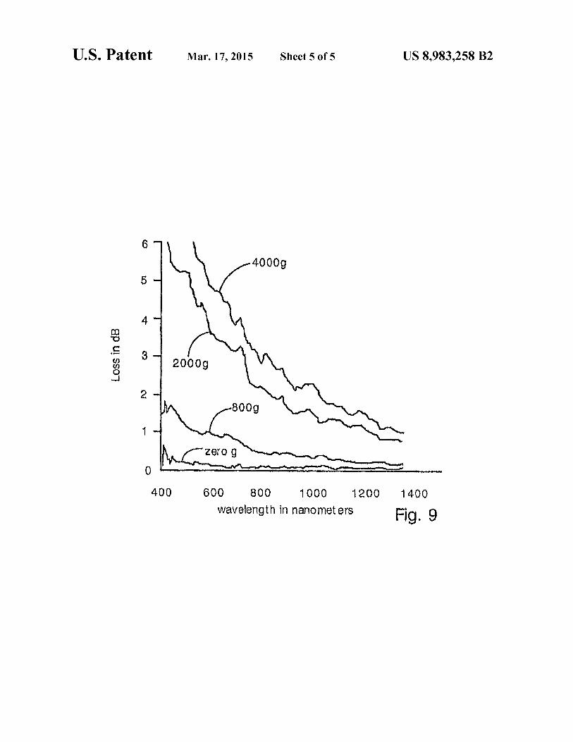
FIG. 9 shows plots of loss versus wavelength when 4000,
2000, and 800 gram weights are rested on a random hole fiber.
DETAILED DESCRIPTION OF THE PREFERRED
EMBODIMENT OF THE INVENTION
The present invention provides a holey optical fiber with a
random array of holes. In the present invention, the holey
optical fiber is made by including a gas-generating material in
the fiber preform. In a typical embodiment, the gas generating
material is located around a solid core (e.g., made of solid
SiO2). The gas generating material may be a nitride ceramic
(e. g., silicon nitride, rare earth nitrides, AlN, TiN) or carbide
ceramic (e.g. silicon carbide, rare earth carbides) that decom-
poses at or close to the fiber drawing temperature (e.g., 1500-
1600 Celsius in the case of pure fused silica fibers). Decom-
position produces gas bubbles (e.g., N2, COz, carbon
monoxide or nitrogen oxides) in the molten preform material
as it is drawn. The gas bubbles are randomly distributed and
are drawn into long thin holes (or tubes) that remain in the
optical fiber. The holes reduce the refractive index in the
region surrounding the solid core, and so provide light con-
finement. The number and size ofthe holes can be influenced
by the preform composition, drawing temperature, parent
material particle size and drawing speed, among other factors.
Though the holes have random locations, they can have non-
uniform distribution by nonuniforrnly distributing the gas
generating material.
FIG. 1 illustrates the present method for making random-
hole optical fiber. In the present method, a fiber preform 18
comprises a silica tube 20 filled with a holey region forming
powder 22 and a solid silica rod 24. The holey region forming
powder 22 forms a fiber cladding and the solid rod 24 forms
a fiber core.
Heaters 26 heat the preform 18 so that it can be pulled to
form a fiber 28, as known in the art.
The holey region forming powder 22 comprises a mixture
of a glass material (e.g., high purity silica powder) and a
gas-generating material (e.g., silicon nitride). The gas gener-
ating material produces a gas when heated above the sintering
temperature ofthe glass material. The gas generating material
can produce gas by thermal decomposition or by chemical
reactions (e.g. oxidation) with other components ofthe holey
region forming powder, for example. The gas generated
within the holey region forming powder 22 forms trapped
bubbles 30 as the holey region forming powder 22 sinters and
softens. The bubbles 30 are stretched and drawn into elon-
gated tubes 32 as the fiber 28 is pulled. In preferred embodi-
ments, the glass material is silica, and the gas generating
material is a nitride or carbide ceramic.
FIG. 2 shows a magnified, cross sectional view of the
present random hole optical fiber. The fiber has a core 34
formed from the solid rod 24, and a solid covering 36 formed
from the tube 20. A holey region 38 provides a cladding
around the core 34. The holey region is formed from the holey
region forming powder 22 and contains a large number (e. g.,
>50 or >200) of holes 40. The holes 40 are created from the
bubbles 30. The holes 40 are preferably long tubes that may
be centimeters, meters, or kilometers long, for example,
depending upon the size ofthe starting bubble in the preform
and the additional gas generated (if any) during the drawing
ofthe bubble into the tube. The holes will typically have finely
tapered ends, such that the diameter ofthe tube will reduce in
size gradually as it reaches the end. The holes may have
typical diameters of0.01 -5 microns, for example, and may be
even smaller at the ends. The holes can be as large as tens of
microns. The holes typically lack continuity, but new ones
10
15
20
25
30
35
40
45
50
55
60
65
4
form as old ones end so that the holey region 38 has a rela-
tively constant porosity. The holes 40 are filled with gas and
so tend to reduce the average refractive index of the cladding
region 38. As a result, optical energy will be confined within
the core 34 as known in the art. In preferred embodiments, the
holes 40 are smaller than a wavelength of light in the fiber
core, so that optical energy is minimally perturbed by indi-
vidual bubbles 40. Very small holes (e.g., less than 100 nm in
diameter) may be required in applications where perturbation
of the optical energy is undesirable.
The holey region forming powder 20 comprises mostly
glass material (e. g., high purity silica powder) with a portion
of a gas generating material. The gas generating material is
preferably a ceramic (e.g., nitride or carbide) that generates
gas at or close to the temperature required for fiber drawing.
For example, the gas generating material can generate gas at
temperatures in the range of about 1000-1600 C. for silica
fibers. The gas generating material should generate gas at
temperatures above the sintering temperature of the holey
region forming powder so that generated gas is trapped and
cannot escape. The gas can be generated by decomposition
and/or oxidation, for example. The gas that forms the bubbles
30 can be any gas, but is preferably a relatively inert gas that
does not interfere with desired light transmission properties
of the optical fiber.
In a preferred embodiment, the gas generating material is
silicon nitride. The silicon nitride can be a powder mixed into
the holey region forming powder 22. Alternatively, the silicon
nitride can be a coating on the particles of glass material.
Silicon nitride is a preferred material for generating the gas
bubbles 30 because it produces a relatively large amount of
gas at the drawing temperature, and because it oxidizes to
SiO2 (a preferred fiber material) during drawing. Silicon
nitride is a preferred gas generating material when silica is the
glass material.
Silicon nitride can be present in amounts less than about
1% by weight of the holey region forming powder when the
balance is silica. In optical fibers manufactured by the present
inventors, silicon nitride comprises about 0.01 -0.5%, or,
more typically, 0.04-0.l% of the holey region forming pow-
der by weight, with the balance of the holey region forming
powder being high purity silica. The amount of silicon nitride
will influence the porosity of the holey region. Larger
amounts of silicon nitride will tend to produce higher poros-
ity, and hence, a relatively lower average refractive index in
the holey regions.
The porosity of the holey region can vary widely. For
example, the present invention can produce porosities from
less than 1% to 95% and higher. Low porosities can be used in
the cladding region of index-guiding fiber. High porosities
can be used to reduce optical loss from Rayleigh scattering,
for example.
While not wishing to be limited to a specific mechanism, it
is believed by the present inventors that silicon nitride pro-
duces gas by oxidation during drawing. Oxygen present in the
holey region forming powder oxidizes the silicon nitride,
producing SiOz, and nitrogen or nitrogen oxides or some
mixture thereof. Oxygen might also oxidize the nitrogen to
form mixed nitrogen oxides. The oxygen may be adsorbed on
the surfaces ofholey region forming powderparticles, may be
trapped in voids during sintering, or may be dissolved in the
silica. Oxygen bound to silica may also contribute to the
oxidation. The nitrogen and nitrogen oxide gases may remain
in the holes of the final, drawn fiber.
It is noted that oxygen or other gases (e. g., inert gases) may
be incorporated into the holey region forming powder during
drawing. For example, flowing oxygen gas into the holey

US 8,983,258 B2
5
region forming powder may increase the oxidation of the
silicon nitride and gas generation. The fiber preform can also
be filled with ambient air. Solid oxygen sources (e. g., nitrates)
can also be incorporated into the holey region forming pow-
der.
The holey region forming powder can have a wide range of
particle sizes. Typical fibers made by the present inventors
have employed 325 mesh and 100 mesh silica powder and
sub-micron diameter silicon nitride powder. Other particle
sizes can also be used and may influence the size of the holes
40 or porosity of the holey region. The size of the powder
particles can affect the sintering temperature and amount of
gas generated. Ifmixtures ofpowders are used, they should be
thoroughly mixed before drawing, unless non-uniform hole
distributions are desired.
It is noted that pre-oxidation ofthe gas generating material,
drawing speed, pulling force and drawing temperature may
also influence the porosity of the holey regions or the size of
the holes.
The glass material of the holey region forming powder is
preferably high purity silica. However, other glassy materials
can be used instead. For example, fluoride-containing
glasses, borosilicate glasses, or other optical glasses can be
used instead of silica. These other glasses may require differ-
ent drawing conditions (e.g. different temperatures, absence
of oxygen) and so may require use with specific gas generat-
ing materials.
Silicon carbide can also be used as the gas generating
material. Silicon carbide tends to oxidize in the presence of
oxygen at high temperature, forming SiO2 and carbon mon-
oxide or carbon dioxide. The carbon monoxide or carbon
dioxide provides the bubbles 30. The oxygen source can be
elemental oxygen present in the preform. Pure gaseous oxy-
gen can be flowed into the preform to increase the amount of
available oxygen. However, it has been empirically observed
that silicon carbide tends to form less gas than silicon nitride,
on a weight percentage basis. For this reason, the holey region
forming powder may require more than 1% by weight silicon
carbide (e.g., l-5%) for adequate gas generation, when com-
bined with silica. Of course, the required amount of silicon
carbide depends upon the desired porosity and application of
the optical fiber.
Many materials other than silicon nitride and silicon car-
bide can be used as the gas generating material. It is noted
that, in general, the gas generating material should have the
following characteristics:
1) The gas generating material should produce gas at a
temperature at or above the sintering temperature ofthe holey
region forming powder. If the gas generating material pro-
duces all of its gas at a temperature below the sintering tem-
perature ofthe powder, then gas will not be trapped within the
preform, and bubbles will not be formed. Sintering tempera-
ture will be affectedby heating duration, particle size, particle
compaction, and particle surface chemistry. For example, 325
mesh silica powder typically can be sintered at about 1000-
1500 Celsius. Silicon nitride is suitable for use with silica
because it continues to produce gas at typical silica sintering
temperatures.
2) The gas generating material should produce gases that
do not impair desired optical properties ofthe optical fiber. In
many cases, and depending upon the application, the reaction
products of the gas generating material must not exhibit too
high ofoptical losses to the propagating signal. Silicon nitride
meets this guideline because the nitrogen, nitrogen oxides
and SiO2 do not interfere with optical transmission signifi-
cantly in most of the wavelength regions of interest (e.g.,
optical and near-infrared).
10
15
20
25
30
35
40
45
50
55
60
65
6
It is noted that many nitride materials can be used as the
gas-generating material. Examples of possible nitride mate-
rials that can be used include aluminum nitride, titanium
nitride, rare earth metal nitrides (e. g. erbium nitride, nyo-
dimuim nitride), and boron nitride. Other metal nitrides or
intermetallic nitrides can also be used. Metal nitrides and
intermetallic nitrides tend to decompose at high temperature,
or oxidize in the presence of oxygen, thereby forming gas
bubbles of nitrogen or nitrogen oxides.
Also, many carbide materials can be used as the gas gen-
erating material. Carbide materials that can be used include
aluminum carbide, titanium carbide, rare earth carbides and
other metal or intermetallic carbides. Carbide materials tend
to decompose and oxidize into carbon dioxide and carbon
monoxide in the presence of oxygen.
Also, nitrate and carbonate compounds may be used as the
gas generating material. The nitrate or carbonate material
should be a metal compound. For example, sodium nitrate or
sodium carbonate can be used. Nitrates will form nitrogen,
nitrogen oxides, and possibly oxygen; carbonates will form
carbon dioxide, carbon monoxide and possibly oxygen. The
nitrate or carbonate material can be added to the preform as a
powder, or an aqueous solution, for example. Other nitrates or
carbonates that can be used include potassium nitrate or car-
bonate, rare earth nitrates and carbonates, and aluminum
nitrate or carbonate.
Rare earth metal nitrides, carbides, nitrates and carbonates,
in addition to providing gas bubbles, can provide rare earth
dopants (e. g., erbium, neodymium, etc.) or other dopants with
desirable optical functions such as optical amplification, fluo-
resence or frequency shifting. Other dopants can also be
incorporated into the fiber. Useful optical properties of rare
earth dopants and other dopants are known in the art.
It is also noted that rare earth dopants or other dopants can
be incorporated into the holey region forming powder as
dopants in the glass material.
In another aspect ofthe invention, a liquid precursor mate-
rial is used to provide the gas generating material. The liquid
precursor can decompose with heating to produce carbides or
nitrides that subsequently release bubble-forming gas. In this
embodiment, the liquid precursor is mixed with glass powder
to form the holey region forming powder. The holey region
forming powder will be a slurry or paste in this embodiment.
The liquid precursor can be a polysilizane (e.g. polyureasili-
zane), alumoxane, or polyurethane, or other suitable liquid as
know in the art to produce solid compounds that generate
gases when heated. Specifically, these liquid materials are
known to form nitrides and carbides when heated. The choice
of liquid precursor will in general be subject to the consider-
ations addressed above, including decomposition tempera-
ture, gases produced and resulting oxidation processes. An
advantage of using a liquid precursor is that the liquid forms
coatings or particles of gas generating material with
extremely high uniformity. For example, the liquid precursor
may form a thin coating of gas generating material on each
particle of glass material in the holey region forming powder.
A coating on each particle will tend to produce more uniform
distribution of gas generating material compared to a mixture
of particles. A highly uniform distribution of gas generating
material will tend to create a highly uniform distribution of
holes, and holes with smaller sizes. Uniform hole distribution
and small hole size are typically preferred in optical fiber
applications.
To control the amount ofgas generating material created by
the liquid precursor, the liquid precursor can be diluted with
a solvent. A highly diluted liquid precursor material will tend
to produce fewer bubbles and lower porosity in the optical

US 8,983,258 B2
7
fiber. Solvents that can be used include alcohol, chlorinated
hydrocarbons, acetates, ethers, etc., depending upon the liq-
uid precursor used, with different solvents being suitable for
different precursors, as known in the art. 4h
FIG. 3 shows an alternative optical fiber that has holes in
the core region 34. This fiber can be made by replacing the
solid rod 24 of FIG. 1 with a column of glass powder having
a lower concentration of gas generating material. The glass
powder can be disposed within a hollow tube so that it has a
well defined diameter. The hollow tube could be made of
glass and remain during the draw or could be withdrawn
before the fiber drawing occurs so that the tube is not incor-
porated into the fiber. Alternatively, the tube could be made
from a thin polymeric material that vaporizes at low tempera-
ture. A possible advantage of providing holes in the core
region is that it could reduce Rayleigh scattering and optical
loss by minimizing the amount ofglass material in the core. In
order to reduce Rayleigh scattering as much as possible, high
porosities may be desirable. For example, the core may have
a 97% porosity and the cladding a 98% porosity.
Many other fiber structures are also possible in the present
invention. FIG. 4, for example, shows a cross-section of an
optical fiber with random holes generated by gas 40, in com-
bination with an organized array of six holes 42 formed from
drawn hollow glass tubes. This embodiment can be created by
stacking six hollow glass tubes around the solid rod 34 in the
preform ofFIG. 1, as known in the conventional art ofmaking
holey fibers. The space around the tubes is filled with holey
region forming powder.
FIG. 5 shows a cross-section of an optical fiber with a
non-uniform distribution of random holes 40. The fiber of
FIG. 5 may have strong birefringence and may have useful
polarization maintaining properties. The fiber of FIG. 5 can
be made by non-uniformly distributing gas generating mate-
rial in the preform. Alternatively, the fiber of FIG. 5 can be
made by including large D-shaped solid glass rods in the
preform.
FIG. 6 shows another embodiment of the invention in
which holey regions are confined within two drawn hollow
glass tubes 44. Areas 46 outside the tubes 44 may be created
from glass powder lacking gas generating material or having
a smaller amount ofgas generating material. The fiber ofFIG.
6 can be made by packing tubes 44 with holey region forming
powder before drawing.
It is noted that many different fiber structures can be made
by combining gas generating powder with glass powder, hol-
low glass tubes, and solid glass tubes. Holey regions can be
localized by disposing gas generating material within a hol-
low glass tube. Solid regions can be created from glass pow-
der lacking gas generating material or from using solid glass
elements. An infinite variety of structures are possible within
the scope of the present invention.
The present random hole optical fibers are pressure sensi-
tive and can be used in pressure and force sensing applica-
tions. Specifically, the random hole fiber experiences an
increase in optical loss when pressure is applied in a direction
orthogonal to the fiber axis, or when the pressure is hydro-
statically applied.
The optical loss ofthe random hole fiber varies with wave-
length. The loss is generally greater for relatively short wave-
lengths (e.g., wavelengths shorter than 600 nm) than for long
wavelengths. However, the wavelength dependence of loss is
complex and a function of the physical structure of the fiber.
The random hole fiber is sensitive to linear force, and to
isotropic hydrostatic pressure applied by a fluid medium. A
linear force can be applied by placing a weight on top of the
fiber, for example.
10
15
20
25
30
35
40
45
50
55
60
65
8
FIG. 7 shows a simple pressure sensor according to the
present invention having a section of random hole optical
fiber 50. The optical loss of the optical fiber is responsive to
applied pressure 52. The applied pressure can therefore be
determined by monitoring the loss ofthe fiber with an optical
detector.
FIG. 8 shows plots of optical loss as a function of wave-
length for a random hole optical fiber. The fiber has a solid
core and a holey cladding, like the fiber of FIG. 2. FIG. 8
illustrates the optical loss when a 300-gram weight rests on a
5 centimeter length of the fiber, and the optical loss when a
500-gram weight rests on a 5 centimeter length of the fiber.
The optical loss increases substantially in the short wave-
length (i.e. less than 600 nm) as the weight is increased. The
optical loss continues to increase as the weight is increased
beyond 500 grams, although this is not illustrated. Optical
loss can be used to determine pressure or force applied to the
fiber.
FIG. 9 shows plots of optical loss as a function of wave-
length for a random hole fiber different from the fiber used to
generate FIG. 8. The fiber used to generate FIG. 9 has a solid
core and a holey cladding, like the fiber of FIG. 2. FIG. 9
illustrates the optical loss when 4000 g, 2000 g, and 800 g,
weights rest on 2.85 centimeter lengths of the fiber. Also, the
loss with zero pressure applied (zero weight) is also shown.
From FIG. 9 it is clear that the optical loss increases dramati-
cally with increasing pressure.
It is noted that the optical loss due to pressure or applied
force is repeatable and does not exhibit hysteresis. Repeated
tests confirm that applied pressure does not produce perma-
nent alterations in the optical loss ofthe fiber. Also, it is noted
that the optical loss is relatively insensitive to temperature
changes. These features make the present random hole optical
fibers ideal for applications in pressure and force sensing
applications. Also, the relative lack of pressure sensitivity in
the longer wavelengths provides a ready means for calibrat-
ing such a sensor, and providing self-calibration during
operation.
Additionally, it is noted that the pressure measurement
provided by optical loss variations is a distributed measure-
ment. The optical loss is a function ofthe pressure magnitude
in addition to the length of fiber experiencing the pressure.
While not wishing to be limited to a specific mechanism, it
is believed that pressure induced loss in the random hole
optical fibers is a result of stress induced birefringence, opti-
cal tunneling, or highly localized microbends. The random
pattern of holes may create nonuniform structural deforma-
tion in the fiber, and therefore loss-inducing microbends.
The present random hole optical fiber can be used to sense
force or pressure in a wide range of sensing applications. The
fiber can be used to detect pressure by monitoring the amount
of optical loss detected.
The present method for making random hole optical fiber
provides several significant advantages including ease offab-
rication, potential for continuous fiber drawing, and lower
fabrication costs compared to convention techniques formak-
ing holey fiber.
It will be clear to one skilled in the art that the above
embodiment may be altered in many ways without departing
from the scope ofthe invention. Accordingly, the scope ofthe
invention should be determined by the following claims and
their legal equivalents.
What is claimed is:
1. A method for making a random hole optical fiber, com-
prising the steps of:
heating a fiber preform containing a gas generating mate-
rial that generates gas bubbles when heated; and

US 8,983,258 B2
9
drawing the heated fiber preform so that the bubbles are
drawn into tubes wherein said step ofdrawing comprises
forming:
a core composed of a glass of a refractive index; and
a cladding region composed of the same glass of the same
refractive index, wherein the cladding region contains
tubes which are random in diameter, length and radial
position within the cladding region, and wherein the
tubes taper on the ends.
2. The method ofclaim 1, wherein the ends ofthe tubes are
tapered such that significant scattering oflight does not occur.
3. The method of claim 1, wherein an optical loss of the
fiber is less than 1 dB/m.
4. The method of claim 3, wherein the optical loss as
measured at 1550 nm is less than 0.5 dB/m.
5. The method of claim 3, wherein the optical loss as
measured at 1310 nm is less than 0.5 dB/m.
6. The method of claim 3, wherein the optical loss as
measured at 850 nm is less than 0.5 dB/m.
7. The method of claim 3, wherein the optical loss as
measured in the range between 1550 and 1700 nm is less than
0.5 dB/m.
8. The method ofclaim 3, whereby the optical loss induced
by a half inch diameter bend in the fiber is less than 0.5 dB.
9. The method ofclaim 3, wherein the optical loss induced
by a halfinch diameter bend in the fiber is less than 0.5 dB and
more preferably less than 0.1 dB when measured at a wave-
length of 850 nm.
10. The method ofclaim 3, wherein the optical loss induced
by a halfinch diameter bend in the fiber is less than 0.5 dB and
more preferably less than 0.1 dB when measured at a wave-
length of 1310 nm.
10
15
20
25
30
1 0
1 1. The method ofclaim 3, wherein the optical loss induced
by a halfinch diameter bend in the fiber is less than 0.5 dB and
more preferably less than 0.1 dB when measured at a wave-
length of1550 nm.
12. The method ofclaim 3, wherein the optical loss induced
by a halfinch diameter bend in the fiber is less than 0.5 dB and
more preferably less than 0.1 dB when measured in the wave-
length range from of 1550-1700 nm.
13. The method of claim 1, wherein the core of the fiber
when viewed in cross-section is located at a center ofthe fiber,
such that a center of the core is coincident with the center of
the fiber.
14. The method ofclaim 1, wherein optical confinement is
achieved by incorporation ofthe tubes into the fiber such that
an interface between a solid central glass region and a sur-
rounding region containing the tubes defines an interface
between the core and cladding region.
15. The method of claim 14, wherein the tubes in the
cladding region lower an average effective refractive index of
that region, thereby producing a difference in refractive index
between the core and cladding region necessary for optical
confinement to be achieved in the core of the fiber.
16. The method ofclaim 15, wherein the tubes are random
in diameter, random in length and random in spatial position
within the cladding region and such that ifthe tubes were not
present, no cladding would exist.
17. The method of claim 16, wherein the tubes in the
cladding region end by forming a tapered region such that an
inner diameter of the tube decreases continuously to a very
small value relative to an initial diameter of the tube.
18. The method of claim 17, wherein the tubes are adia-
batically tapered.

UNITED STATES PATENT AND TRADEMARK OFFICE
CERTIFICATE OF CORRECTION
PATENT NO. : 8,983,258 B2 Page 1 of]
APPLICATION NO. : 14/023031
DATED : March 17, 2015
INVENTOR(S) : Jeong 1. Kim
It is certified that error appears in the above-identified patent and that said Letters Patent is hereby corrected as shown below:
Specification
Column 1, after the Title please add the following:
--STATEMENT OF GOVERNMENT INTEREST
This invention was made with government support under Grant No. F49620-01-1-0191
awarded by the US Air Force Office of Scientific Research. The government has certain rights in
the invention--
Signed and Sealed this
Thirteenth Day of October, 2015
WMXKAL.Michelle K. Lee
Director ofthe United States Patent and Trademark Oflice