117-10 Specification for Tolerances for Concrete ...dl.mycivil.ir/dozanani/ACI/ACI 117-10...
80
ACI 117-10 Specification for Tolerances for Concrete Construction and Materials (ACI 117-10) and Commentary An ACI Standard Reported by ACI Committee 117
Transcript of 117-10 Specification for Tolerances for Concrete ...dl.mycivil.ir/dozanani/ACI/ACI 117-10...

ACI 117-10
Specification for Tolerances forConcrete Construction and Materials
(ACI 117-10) and CommentaryAn ACI Standard
Reported by ACI Committee 117

American Concrete Institute®
Advancing concrete knowledge
Specification for Tolerances for Concrete Construction and Materialsand Commentary
First printingJune 2010
ISBN 978-0-87031-379-0
Copyright by the American Concrete Institute, Farmington Hills, MI. All rights reserved. This materialmay not be reproduced or copied, in whole or part, in any printed, mechanical, electronic, film, or otherdistribution and storage media, without the written consent of ACI.
The technical committees responsible for ACI committee reports and standards strive to avoid ambiguities,omissions, and errors in these documents. In spite of these efforts, the users of ACI documents occasionallyfind information or requirements that may be subject to more than one interpretation or may beincomplete or incorrect. Users who have suggestions for the improvement of ACI documents arerequested to contact ACI. Proper use of this document includes periodically checking for errata atwww.concrete.org/committees/errata.asp for the most up-to-date revisions.
ACI committee documents are intended for the use of individuals who are competent to evaluate thesignificance and limitations of its content and recommendations and who will accept responsibility for theapplication of the material it contains. Individuals who use this publication in any way assume all risk andaccept total responsibility for the application and use of this information.
All information in this publication is provided “as is” without warranty of any kind, either express or implied,including but not limited to, the implied warranties of merchantability, fitness for a particular purpose ornon-infringement.
ACI and its members disclaim liability for damages of any kind, including any special, indirect, incidental,or consequential damages, including without limitation, lost revenues or lost profits, which may resultfrom the use of this publication.
It is the responsibility of the user of this document to establish health and safety practices appropriate tothe specific circumstances involved with its use. ACI does not make any representations with regard tohealth and safety issues and the use of this document. The user must determine the applicability of allregulatory limitations before applying the document and must comply with all applicable laws and regulations,including but not limited to, United States Occupational Safety and Health Administration (OSHA) healthand safety standards.
Order information: ACI documents are available in print, by download, on CD-ROM, through electronicsubscription, or reprint and may be obtained by contacting ACI.
Most ACI standards and committee reports are gathered together in the annually revised ACI Manual ofConcrete Practice (MCP).
American Concrete Institute38800 Country Club DriveFarmington Hills, MI 48331U.S.A.Phone: 248-848-3700Fax: 248-848-3701
www.concrete.org

117-1
ACI 117-10 supersedes ACI 117-06 and was adopted March 1, 2010 and publishedJune 2010.
Copyright © 2010, American Concrete Institute.All rights reserved including rights of reproduction and use in any form or by any
means, including the making of copies by any photo process, or by electronic ormechanical device, printed, written, or oral, or recording for sound or visual reproductionor for use in any knowledge or retrieval system or device, unless permission in writingis obtained from the copyright proprietors.
ACI Committee Reports, Guides, Manuals, and Commentariesare intended for guidance in planning, designing, executing,and inspecting construction. This document is intended for theuse of individuals who are competent to evaluate thesignificance and limitations of its content and recommendationsand who will accept responsibility for the application of thematerial it contains. The American Concrete Institute disclaimsany and all responsibility for the stated principles. The Instituteshall not be liable for any loss or damage arising therefrom.
Reference to this document shall not be made in contractdocuments. If items found in this document are desired by theArchitect/Engineer to be a part of the contract documents, theyshall be restated in mandatory language for incorporation bythe Architect/Engineer.
ACI 117 Specification and Commentary are presented in a side-by-side column format, with code text placed in the left columnand the corresponding commentary text aligned in the rightcolumn. To distinguish the specification from the commentary, thespecification has been printed in Helvetica, which is the typefacefor this paragraph.
The Commentary is printed in Times Roman, which is the typeface forthis paragraph. Commentary section numbers are preceded by the letter“R” to distinguish them from specification section numbers. Thecommentary is not a part of ACI Specification 117-10.
Specification for Tolerances for Concrete Construction and Materials (ACI 117-10)
and CommentaryAn ACI Standard
Reported by ACI Committee 117
ACI 117-10
Specification synopsis: This specification provides standard tolerances for concrete construction and materials. This document is intended to be usedby specification writers and ACI committees writing standards as the reference document for establishing tolerances for concrete constructionand materials.
Commentary synopsis: This report is a commentary on the “Specifications for Tolerances for Concrete Construction and Materials (ACI 117).” It is intendedto be used with ACI 117 for clarity of interpretation and insight into the intent of the committee regarding the application of the tolerances set forth therein.
Keywords: architectural concrete; concrete; construction; drilled piers; formwork; foundation; mass concrete; pier; precast concrete; prestressed concrete;reinforced concrete; reinforcement; specification; splice; tilt-up concrete; tolerances.
Scott M. Anderson Allen Face Donald M. Marks David N. Peterson
Karl J. Bakke Robert A. Halvorson Ross S. Martin William S. Phelan
David K. Ballast Mark G. Josten Steven W. McCrary B. Duke Pointer
Bryan M. Birdwell Richard L. Knox Arthur W. McKinney Peter J. Ruttura
Gregory P. Birley Jeff L. LaRue Colin T. Milberg Michael J. Schneider
Thomas J. Downs Michael W. Lee William R. Nash Bruce A. Suprenant
Ron Eldridge Michael L. Leming Bob L. Payne Michael A. West
Eldon G. TippingChair
Scott Michael AndersonSecretary

117-2 ACI STANDARD/COMMENTARY
CONTENTSIntroduction, p. 117-3
Section 1—General requirements, p. 117-51.1—Scope1.2—Requirements1.3—Definitions1.4—Referenced standards
Section 2—Materials, p. 117-132.1—Reinforcing steel fabrication and assembly2.2—Reinforcement location2.3—Placement of embedded items, excluding dowels in
slabs-on-ground2.4—Concrete batching2.5—Concrete properties
Section 3—Foundations, p. 117-253.1—Deviation from plumb3.2—Deviation from location3.3—Deviation from elevation3.4—Deviation from plane3.5—Deviation from cross-sectional dimensions of
foundations
Section 4—Cast-in-place concrete for buildings,p. 117-31
4.1—Deviation from plumb4.2—Deviation from location4.3—Not used4.4—Deviation from elevation4.5—Deviation from cross-sectional dimensions4.6—Deviation from formed opening width or height4.7—Deviation from relative elevations or widths for stairs4.8—Deviation from slope or plane4.9—Sawcut depth in slab-on-ground
Section 5—Cast-in-place concrete at interface with precast concrete (except tilt-up concrete), p. 117-45
5.1—Deviation from elevation—cast-in-place concrete5.2—Deviation from location—cast-in-place concrete5.3—Deviation from dimension—cast-in-place concrete5.4—Deviation from plane at bearing surface—cast-in-
place concrete measured over length or width ofbearing surface
Section 6—Masonry, p. 117-51This section has been removed.
Section 7—Cast-in-place, vertically slipformed building elements, p. 117-53
7.1—Deviation from plumb for buildings and cores7.2—Horizontal deviation7.3—Cross-sectional dimensions7.4—Openings through elements7.5—Embedded plates7.6—Deviation from plumb for slipformed and jump-
formed silos
Section 8—Mass concrete, p.117-558.1—Deviation from plumb
8.2—Horizontal deviation8.3—Vertical deviation8.4—Cross-sectional dimension8.5—Deviation from plane
Section 9—Canal lining, p. 117-579.1—Horizontal deviation9.2—Vertical deviation9.3—Cross-sectional dimensions
Section 10—Monolithic water-conveying tunnels, siphons, conduits, and spillways, p. 117-59
10.1—Horizontal deviation10.2—Vertical deviation10.3—Cross-sectional dimensions10.4—Deviation from plane
Section 11—Cast-in-place bridges, p. 117-6111.1—Deviation from plumb11.2—Horizontal deviation11.3—Vertical deviation11.4—Length, width, or depth of specified elements11.5—Deviation from plane11.6—Deck reinforcement cover11.7—Bearing pads
Section 12—Exterior pavements and sidewalks,p. 117-63
12.1—Horizontal deviation12.2—Vertical deviation of surface
Section 13—Chimneys and cooling towers,p. 117-65
13.1—Deviation from plumb13.2—Outside shell diameter13.3—Wall thickness
Section 14—Cast-in-place nonreinforced pipe, p.117-67
14.1—Wall thickness14.2—Pipe diameter14.3—Offsets14.4—Surface indentations14.5—Grade and alignment14.6—Concrete slump
Section 15—Tilt-up concrete, p. 117-6915.1—Panel forming15.2—Deviation from plumb15.3—Deviation from elevation15.4—Deviation from location15.5—Deviation from slope or plane15.6—Deviation from relative widths
Notes to Specifier, p. 117-73General notes
Foreword to checklists, p. 117-75
Mandatory Requirements Checklist, p. 117-75
Optional Requirements Checklist, p. 117-76

SPECIFICATION COMMENTARY
TOLERANCES FOR CONCRETE CONSTRUCTION 117-3
INTRODUCTION
This commentary pertains to “Specifications for Tolerancesfor Concrete Construction and Materials (ACI 117-10).”The purpose of the commentary is to provide an illustrativeand narrative complement to the specification; it is not apart of the specification.
No structure is exactly level, plumb, straight, and true.Tolerances are a means to establish permissible variation indimension and location, giving both the designer and thecontractor limits within which the work is to be performed.They are the means by which the designer conveys to thecontractor the performance expectations upon which thedesign is based or that the project requires. Such specifiedtolerances should reflect design assumptions and projectneeds, being neither overly restrictive nor lenient.
Necessity rather than desirability should be the basis ofselecting tolerances.
As the title “Specifications for Tolerances for ConcreteConstruction and Materials (ACI 117)” implies, the toler-ances given are standard or usual tolerances that apply tovarious types and uses of concrete construction. They arebased on normal needs and common construction tech-niques and practices. Specified tolerances at variance withthe standard values can cause both increases and decreasesin the cost of construction.
Economic feasibility—The specified degree of accuracy hasa direct impact on the cost of production and the constructionmethod. In general, the higher degree of constructionaccuracy required, the higher the construction cost, and thelower the degree of construction accuracy, the higher thecost of required repairs.
Relationship of all components—The required degree ofaccuracy of individual parts can be influenced by adjacentunits and materials, joint and connection details, and thepossibility of the accumulation of tolerances in criticaldimensions.
Construction techniques—The feasibility of a tolerancedepends on available craftsmanship, technology, materials,and project management.
Compatibility—Designers are cautioned to use finish andarchitectural details that are compatible with the type andanticipated method of construction. The finish and archi-tectural details used should be compatible with achievableconcrete tolerances.
117-4 ACI STANDARD/COMMENTARY
SPECIFICATION COMMENTARY
Contract document referencesACI specification documents—The following AmericanConcrete Institute standards provide mandatory tolerancerequirements for concrete construction and can be referencedin Contract Documents:117 Specification for Tolerances for Concrete
Construction and Materials and CommentaryITG-7 Specification for Tolerances for Precast
Concrete301 Specifications for Structural Concrete303.1 Standard Specification for Cast-in-Place
Architectural Concrete336.1 Specification for the Construction of Drilled
Piers530.1/ASCE 6/TMS 602 Specification for Masonry Structures and
Commentary
ACI informative documents—The documents of thefollowing American Concrete Institute committees coverpractice, procedures, and state-of-the-art guidance for thecategories of construction as listed:General building...... ACI 302, 303, 304, 305, 311, 315, 336, 347Special structures..............ACI 207, 307, 313, 325, 332, 334, 358Materials .................................................................. 211, 223Other ................................................................................ 228

SPECIFICATION COMMENTARY
TOLERANCES FOR CONCRETE CONSTRUCTION 117-5
1.1—Scope
1.1.1 This specification designates standard tolerancesfor concrete construction.
1.1.2 The indicated tolerances govern unless other-wise specified.
Tolerances in this specification are for typical concreteconstruction and construction procedures and are appli-cable to exposed concrete and to architectural concrete.Materials that interface with or connect to concreteelements may have tolerance requirements that are notcompatible with those contained in this document.
This specification does not apply to specializedstructures, such as nuclear reactors and containmentvessels, bins, prestressed circular structures, andsingle-family residential construction. It also does notapply to precast concrete or to shotcrete.
Tolerances for specialized concrete construction thatis outside the scope of this specification shall bespecified in Contract Documents.
1.1.3 A series of preconstruction tolerance coordina-tion meetings shall be scheduled and held prior to thecommencement of the Work. The Contractor,subcontractors, material suppliers, and other keyparties shall attend. All parties shall be given theopportunity to identify any tolerance questions andconflicts that are applicable to the work with materials,prefabricated elements, and Work assembled/installedin the field by the Contractor.
1.2—Requirements
1.2.1 Concrete construction and materials shallcomply with specified tolerances.
SECTION 1—GENERAL REQUIREMENTS
R1.1—Scope
R1.1.2 Specification of more restrictive tolerances forspecialized construction, such as architectural concrete,often results in an increase in material cost and time ofconstruction.
R1.1.3 Preconstruction tolerance coordination meetingsprovide an opportunity for key participants to identify and toresolve tolerance compatibility issues prior to construction.
R1.2—Requirements
An example of a specific application that uses a multiple oftoleranced items that together yield a toleranced result is thelocation of the face of a concrete wall. The wall has a toler-ance on location (Section 4.2.1), measured at the foundationof the wall, and is allowed to deviate from the specifiedplane (Sections 4.1 and 4.8.2). The application of the locationtolerance (Section 4.2.1) cannot be used to increase theplumb tolerance contained in Section 4.1. Similarly, thetolerance on member thickness (Section 4.5) shall not beallowed to increase the tolerance envelope resulting from theapplication of Sections 4.1, 4.2.1, and 4.8.2. If the base of thewall is incorrectly located by the maximum amount allowedby Section 4.2.1, then the plumb tolerance (Section 4.1)dictates that the face of the wall move back toward thecorrect location, and at a rate that does not exceed theprovisions of Section 4.8.2. Refer to Fig. R1.2.3.

117-6 ACI STANDARD/COMMENTARY
SPECIFICATION COMMENTARY
1.2.2 Tolerances shall not extend the structure beyondlegal boundaries. Tolerances are measured from thepoints, lines, and surfaces defined in Contract Docu-ments. If application of tolerances causes the extensionof the structure beyond legal boundaries, the tolerancemust be reduced.
1.2.3 Tolerances are not cumulative. The most restrictivetolerance controls.
R1.2.2 If the application of tolerances causes the extensionof the structure beyond legal boundaries, the Architect/Engineer should be notified to initiate conflict resolution.
Fig. R1.2.3—Use of multiple of toleranced items to yield toleranced result.
R1.2.3 Accumulations of individual tolerances on a singleitem should not be used to increase an established tolerance.Individual tolerances are unique to their specific applicationand should not be combined with other tolerances to form atolerance envelope. The separately specified tolerancesmust remain separate and not cumulative.
Each tolerance stands alone when evaluating the accept-ability of concrete construction. Refer to Fig. R1.2.3.
1.2.4 Plus (+) tolerance increases the amount ordimension to which it applies, or raises a deviationfrom level. Minus (–) tolerance decreases the amountor dimension to which it applies, or lowers a deviationfrom level. Where only one signed tolerance is speci-fied (+ or –), there is no specified tolerance in theopposing direction.

TOLERANCES FOR CONCRETE CONSTRUCTION 117-7
SPECIFICATION COMMENTARY
R1.2.5 For acceptance criteria for structural concrete, referto ACI 301, Section 1.7.
R1.3—Definitions
arris—refer to Fig. R1.3.1.
Fig. R1.3.1—Arris.
Fig. R1.3.2—Bowing.
bowing—refer to Fig. R1.3.2.
1.2.5 If the tolerances in this document are exceededfor structural concrete, refer to Contact Documents foracceptance criteria. For other concrete, the Architect/Engineer may accept the element if it meets one of thefollowing criteria:
a) Exceeding the tolerances does not affect thestructural integrity, legal boundaries, or archi-tectural requirements of the element; or
b) The element or total erected assembly can bemodified to meet all structural and architec-tural requirements.
1.3—Definitions
ACI provides a comprehensive list of definitionsthrough an online resource, “ACI Concrete Termi-nology,” http://terminology.concrete.org. Definitionsprovided here complement that resource.
Architect/Engineer—the architect, engineer, architec-tural firm, or engineering firm issuing Contract Docu-ments or administering the Work under ContractDocuments, or both.
arris—the sharp external corner edge that is formedat the junction of two planes or surfaces.
bowing—deviation of the edge or surface of a planarelement from a line passing through any two cornersof the element.
bundled bar equivalent area—total area of reinforcingbars contained in the bundle.
concrete, exposed—concrete surfaces formed so asto yield an acceptable texture and finish for permanentexposure to view.
Contract Documents—a set of documents suppliedby the Owner to the Contractor that serve as the basisfor construction; these documents contain contractforms, contract conditions, specifications, drawings,addenda, and contract changes.
Contractor—he person, firm, or entity under contractfor construction of the Work.

117-8 ACI STANDARD/COMMENTARY
SPECIFICATION COMMENTARY
cover—the least distance between the surface ofembedded reinforcement and the surface of theconcrete.
deviation—departure from an established point, line,or surface; measured normal (perpendicular) to thereference line or surface.
deviation from plane—the distance between a pointon a reference plane and the corresponding point onthe actual plane.
cover—refer to Fig. R1.3.3.
deviation—refer to Fig. R1.3.4.
deviation from plane—refer to Fig. R1.3.5(a) and (b).
Fig. R1.3.3—Cover.
Fig. R1.3.4—Deviation.
Fig. R1.3.5—Deviation from plane.

TOLERANCES FOR CONCRETE CONSTRUCTION 117-9
SPECIFICATION COMMENTARY
deviation, horizontal—departure from an establishedpoint, line, or surface, measured normal (perpendicular)to a vertical line through the point of interest.
deviation, vertical—departure from an establishedpoint, line, or surface, measured normal (perpendicular)to a horizontal line through the point of interest.
deviation , horizontal—refer to Fig. R1.3.6(a), (b), and (c).
Fig. R1.3.6—Horizontal deviation.
Fig. R1.3.7—Vertical deviation
deviation, vertical—refer to Fig. R1.3.7(a) and (b).

117-10 ACI STANDARD/COMMENTARY
SPECIFICATION COMMENTARY
flatness—deviation of a surface from a plane.
footing—a structural element of a foundation thattransmits loads directly to the soil.
foundation—a system of structural elements thattransmit loads from the structure above to the earth.
levelness—deviation of a line or surface from a hori-zontal line or surface.
Project Drawings—graphic presentation of projectrequirements.
Project Specification—the written document thatdetails requirements for the Work in accordance withservice parameters and other specific criteria.
tolerance—the permitted deviation from a specifieddimension, location, or quantity.
Work—the entire construction or separately identifi-able parts thereof required to be furnished underContract Documents.
Vertical deviation, horizontal deviation, and deviation fromplumb are individually used to establish a tolerance envelopefor each deviation type within which permissible variationscan occur. Deviation from plane is used to determine therate of change of adjacent points (slope tolerance) occurringwithin the tolerance envelope. In this fashion, the slope andsmoothness of surfaces and lines within a tolerance envelopeare controlled. Abrupt changes such as offsets, saw-toothing,and sloping of lines and surfaces properly located within atolerance envelope may be objectionable for exposedconcrete. The acceptable relative alignment of points on asurface or line is determined by using a slope tolerance.Effective use of a slope tolerance requires that the specificdistance over which the slope is to be measured is estab-lished, and that the measurement device only contacts thesurface at this specific distance.
flatness—refer to Fig. R1.3.8.
Fig. R1.3.8—Flatness and levelness.
levelness—refer to Fig. R1.3.8.

TOLERANCES FOR CONCRETE CONSTRUCTION 117-11
SPECIFICATION COMMENTARY
1.4—Reference standards
ASTM InternationalC94/C94M-09 Standard Specification for Ready-
Mixed ConcreteC174/C174M-06 Standard Test Method for
Measuring Thickness of ConcreteElements Using Drilled ConcreteCores
C1383-04 Standard Test Method forMeasuring the P-Wave Speed andthe Thickness of Concrete PlatesUsing the Impact-Echo Method
D4748-06 Standard Test Method for Deter-mining Thickness of Bound Pave-ment Layers Using Short-PulseRadar
E1155-96 (2008) Standard Test Method for Deter-mining FF Floor Flatness and FLFloor Levelness Numbers
E1486-98 (2004) Standard Test Method for Deter-mining Floor Tolerances UsingWaviness, Wheel Path and Level-ness Criteria
R1.4—Informative references
The documents listed below were the latest editions at thetime this document was prepared. Because these documentsare revised frequently, the reader is advised to contact theproper sponsoring group if it is desired to refer to the latestversion.
American Concrete Institute301 Specifications for Structural Concrete304.6R Guide for the Use of Volumetric-Measuring and
Continuous Mixing Concrete Equipment318 Building Code Requirements for Structural
Concrete and Commentary
American Institute of Steel ConstructionDesign Guide 1: Base Plates and Anchor Rod Design
American Society of Concrete ContractorsPosition Statement #14—Anchor Bolt Tolerances
ASTM InternationalC685/C685M Standard Specification for Concrete Made by
Volumetric Batching and Continuous Mixing
Concrete Reinforcing Steel Institute10MSP Manual of Standard Practice
Precast/Prestressed Concrete InstituteMNL-116 Manual for Quality Control for Plants and
Production of Structural Precast ConcreteProducts
MNL-135 Tolerance Manual for Precast andPrestressed Concrete Construction
National Ready Mixed Concrete AssociationQuality Control Manual—Section 3; Certification of ReadyMixed Concrete Production Facilities (Checklist)
Volumetric Mixer Manufacturers BureauVMMB 100 Volumetric Mixer Standards of the Volu-
metric Mixer Manufacturers Bureau
These publications may be obtained from:
American Concrete Institute38800 Country Club DriveFarmington Hills, MI 48331www.concrete.org
American Institute of Steel ConstructionOne East Wacker Dr., Suite 700Chicago, IL 60601www.aisc.org
117-12 ACI STANDARD/COMMENTARY
SPECIFICATION COMMENTARY
American Society of Concrete Contractors2025 Brentwood Blvd.St. Louis, MO 63144www.ascconline.org
ASTM International100 Barr Harbor Dr.West Conshohocken, PA 19428www.astm.org
Concrete Reinforcing Steel Institute933 North Plum Grove Rd.Schaumburg, IL 60173www.crsi.org
Precast/Prestressed Concrete Institute200 W. Adams St., #2100Chicago, IL 60606www.pci.org
National Ready Mixed Concrete Association900 Spring StreetSilver Spring, MD 20910www.nrmca.org
Volumetric Mixer Manufacturers Bureau900 Spring StreetSilver Spring, MD 20910www.vmmb.org

SPECIFICATION COMMENTARY
TOLERANCES FOR CONCRETE CONSTRUCTION 117-13
2.1—Reinforcing steel fabrication and assembly
For bars No. 3 through 11 in size, refer to Fig. 2.1(a).
For bars No. 14 and 18 in size, refer to Fig. 2.1(b).
SECTION 2—MATERIALS
Fig. 2.1(a)—Standard fabricating tolerances for bar sizes No. 3 through 11. (Figure courtesy
of Concrete Reinforcing Steel Institute.)

117-14 ACI STANDARD/COMMENTARY
SPECIFICATION COMMENTARY
Fig. 2.1(a) (cont.)—Standard fabricating tolerances for bar sizes No. 3 through 11. (Figure courtesy of Concrete Reinforcing Steel
Institute.)

TOLERANCES FOR CONCRETE CONSTRUCTION 117-15
SPECIFICATION COMMENTARY
Fig. 2.1(b)—Standard fabricating tolerances for bar sizes No. 14 and 18. (Figure courtesy of Concrete Reinforcing Steel Institute.)
117-16 ACI STANDARD/COMMENTARY
SPECIFICATION COMMENTARY
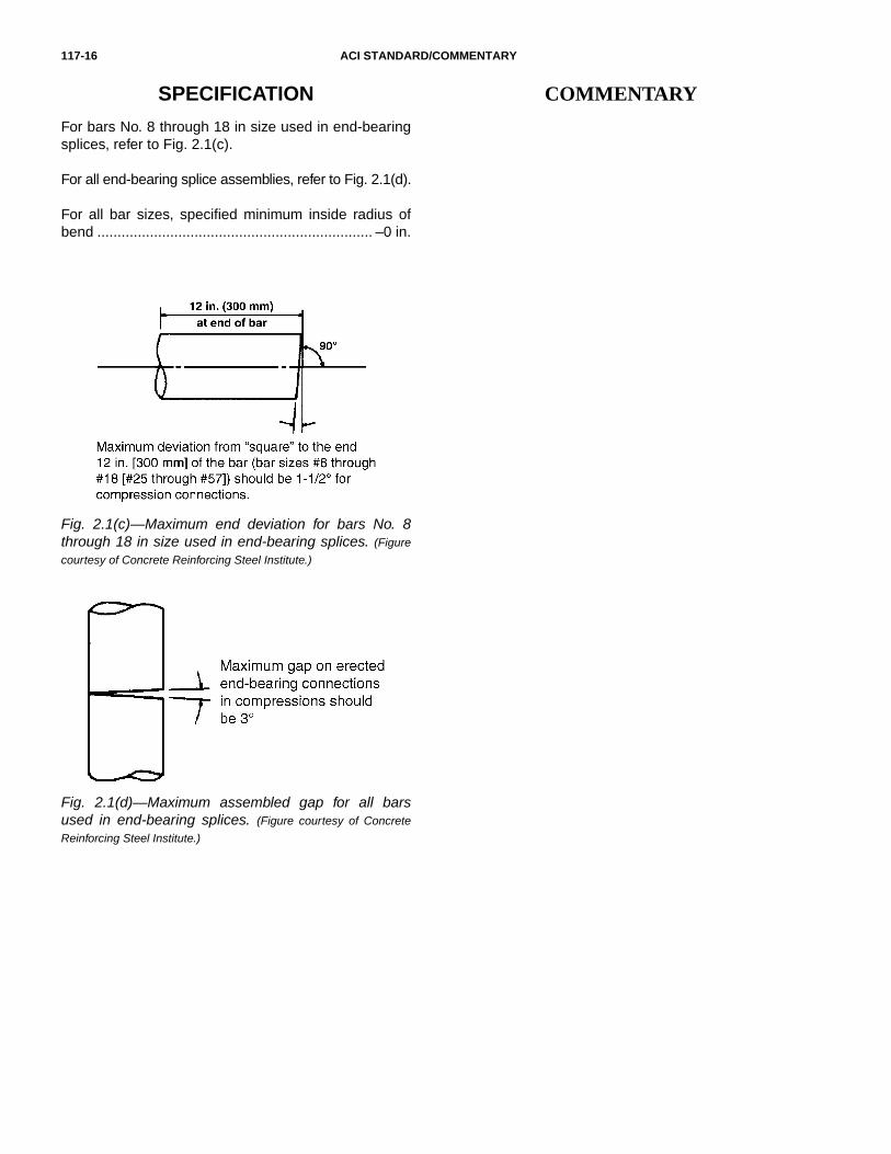
Fig. 2.1(c)—Maximum end deviation for bars No. 8through 18 in size used in end-bearing splices. (Figure
courtesy of Concrete Reinforcing Steel Institute.)
Fig. 2.1(d)—Maximum assembled gap for all barsused in end-bearing splices. (Figure courtesy of Concrete
Reinforcing Steel Institute.)
For bars No. 8 through 18 in size used in end-bearingsplices, refer to Fig. 2.1(c).
For all end-bearing splice assemblies, refer to Fig. 2.1(d).
For all bar sizes, specified minimum inside radius ofbend .................................................................... –0 in.

TOLERANCES FOR CONCRETE CONSTRUCTION 117-17
SPECIFICATION COMMENTARY
R2.2—Reinforcement location
The tolerance for d, as stated in ACI 318, is for use in a strengthcalculation and should not be used as a placementtolerance for construction.
R2.2.1, R2.2.2, and R2.2.3 Tolerances for fabrication,placement, and lap splices for welded wire reinforcementare not covered by ACI 117 and, if required, should bespecified by the Specifier. Before placement of concrete,inspection of reinforcing bars for conformance to specifiedplacement tolerances may involve measurements to form-work or soil. Refer to Fig. R2.2.1(a),(b), and (c). An absolutelimitation on one side of the reinforcement placement isestablished by the limit on the reduction in cover. Refer toFig. R2.2.2(a) to (d) and Fig. R2.2.3.
2.2—Reinforcement location
Fig. R2.2.1—Placement.
2.2.1 Placement of nonprestressed reinforcementWhen member depth (or thickness) is 4 in. or less..........................................................................±1/4 in.
When member depth (or thickness) is over 4 in. andnot over 12 in.....................................................±3/8 in.
When member depth (or thickness) is over 12 in...........................................................................±1/2 in.
2.2.2 Concrete cover measured perpendicular toconcrete surfaceWhen member depth (or thickness) is 12 in. or less..........................................................................–3/8 in.
When member depth (or thickness) is over 12 in...........................................................................–1/2 in.
Reduction in cover shall not exceed 1/3 the specifiedconcrete cover.
Reduction in cover to formed soffits shall not exceed1/4 in.
2.2.3 Vertical deviation for slab-on-ground reinforcement................................................................................±3/4 in.

117-18 ACI STANDARD/COMMENTARY
SPECIFICATION COMMENTARY
Fig. R2.2.2—Cover.
Fig. R2.2.3—Vertical placement.

TOLERANCES FOR CONCRETE CONSTRUCTION 117-19
SPECIFICATION COMMENTARY
2.2.4 Clearance between reinforcement or betweenreinforcement and embedmentOne-quarter specified distance not to exceed.............................................................................±1 in.
Distance between reinforcement shall not be less thanthe greater of the bar diameter or 1 in. for unbundledbars.
For bundled bars, the distance between bundles shallnot be less than the greater of 1 in. or a bar diameterderived from the equivalent total area of all bars in thebundle.
2.2.5 Spacing of nonprestressed reinforcement,measured along a line parallel to the specified spacingExcept as noted below.........................................±3 in.
Stirrups, the lesser of ±3 in. or ±1 in. per ft of beamdepth
Ties, the lesser of ±3 in. or ±1 in. per ft of least columnwidth
The total number of bars shall not be fewer than thatspecified.
R2.2.4 and R2.2.5 The spacing tolerance of reinforcementconsists of an envelope with an absolute limitation on oneside of the envelope determined by the limit on the reductionin distance between reinforcement. In addition, the allowabletolerance on spacing should not cause a reduction in thespecified number of reinforcing bars used. Designers arecautioned that selecting a beam width that exactly meetstheir design requirements may not allow for reinforcementplacement tolerance. This sometimes happens when lap-spliced bars take up extra space and cannot accommodatethe placement tolerance. Where reinforcement quantitiesand available space are in conflict with spacing require-ments of these sections, the Contractor and designer mightconsider bundling a portion of the reinforcement. Bundling ofbars requires approval of the designer. Refer to Fig. R2.2.4(a)to (e) and R2.2.5.
Fig. R2.2.4—Clear distance.

117-20 ACI STANDARD/COMMENTARY
SPECIFICATION COMMENTARY
2.2.6 Placement of prestressing reinforcement orprestressing ducts, measured from form surface
2.2.6.1 Horizontal deviationElement depth (or thickness) 24 in. or less ...........±1/2 in.
Element depth (or thickness) over 24 in. .......... ±1 in.
2.2.6.2 Vertical deviationElement depth (or thickness) 8 in. or less ........ ±1/4 in.
Element depth (or thickness) over 8 in. and not over24 in. ................................................................ ±3/8 in.
Element depth (or thickness) more than 24 in..... ±1/2 in.
R.2.2.6 The vertical deviation tolerance should be consideredin establishing minimum prestressing tendon covers, partic-ularly in applications exposed to deicer chemicals or salt-water environments where use of additional cover isrecommended to compensate for placing tolerances. Slabbehavior is relatively insensitive to horizontal location oftendons. Refer to Fig. R2.2.6(a) and (b).
Fig. R2.2.5—Reinforcement spacing.
Fig. R2.2.6—Prestressing reinforcement placement.
R2.2.7 and R2.2.8 The tolerance for the location of the endsof reinforcing steel is determined by these two sections.
2.2.7 Longitudinal location of bends in bars and endsof barsAt discontinuous ends of corbels and brackets ... ±1/2 in.
At discontinuous ends of other elements ............ ±1 in.
At other locations................................................. ±2 in.
2.2.8 Embedded length of bars and length of bar lapsNo. 3 through 11 bar sizes .................................. –1 in.
No. 14 and 18 bar sizes....................................... –2 in.

TOLERANCES FOR CONCRETE CONSTRUCTION 117-21
SPECIFICATION COMMENTARY
2.2.9 Bearing plate for prestressing tendons, deviationfrom specified plane.................. ±1/4 in. per ft, but not less than ±1/8 in.
R2.2.9 The tolerance for conformance of prestressingtendon bearing plates to the specified plane is established bythis section. Refer to Fig. R2.2.9.
2.2.10 Placement of smooth rod or plate dowels inslabs-on-ground
2.2.10.1 Centerline of dowel, vertical deviationmeasured from bottom of concrete slab at the joint forelement depth 8 in. or less................................±1/2 in.
When element depth is over 8 in. ........................±1 in.
2.2.10.2 Spacing of dowels, measured along a lineparallel to the specified spacing...........................±3 in.
The total number of dowels shall not be fewer than thatspecified.
2.2.10.3 Centerline of dowel with respect to ahorizontal line that is perpendicular to the planeestablished by the jointHorizontal deviation ..........................................±1/2 in.
Vertical deviation...............................................±1/2 in.
R2.2.10 The tolerance for placement of dowels is determinedby this section. Refer to Fig. R2.2.10.1, R2.2.10.2, andR2.2.10.3.
Fig. R2.2.10.1—Dowel placement.
Fig. R2.2.10.2—Dowel spacing.
Fig. R2.2.10.3—Dowel deviation from line.
Fig. R2.2.9—Bearing plate for prestressing tendons.

117-22 ACI STANDARD/COMMENTARY
SPECIFICATION COMMENTARY
2.3—Placement of embedded items, excluding dowels in slabs-on-ground
2.3.1 Clearance to nearest reinforcement shall be thegreater of the bar diameter, largest aggregate size, or.............................................................................. 1 in.
2.3.2 Centerline of assembly from specified location
Horizontal deviation............................................. ±1 in.
Vertical deviation ................................................. ±1 in.
R2.3—Placement of embedded items,excluding dowels in slabs-on-ground
R2.3.1 The minimum clearance between reinforcement andembedded items is determined by this section. Refer toFig. R2.3.1(a) and (b).
Fig. R2.3.1—Clear distance.
R2.3.3 The tolerance for the elevation of the top of anchorbolts is consistent with that contained in the American Instituteof Steel Construction’s Code of Standard Practice (10MSP).The tolerance for the location of anchor bolts is based onusing oversized holes per the AISC Design Guide 1: BasePlates and Anchor Rod Design, recommendations of theStructural Steel Educational Council, and concrete contractoranchor bolt placement techniques. Refer to the AmericanSociety of Concrete Contractor’s Position Statement #14.
2.3.3 Surface of assembly from surface of element
Assembly dimension 12 in. or smaller......................................................... ±1/2 in. per 12 in.but not less than ............................................... ±1/4 in.
Assembly dimension greater than 12 in. .......... ±1/2 in.
2.3.4 Anchor bolts in concrete
2.3.4.1 Top of anchor bolt from specified elevationVertical deviation .............................................. ±1/2 in.
2.3.4.2 Centerline of individual anchor bolts fromspecified location
Horizontal deviationfor 3/4 in. and 7/8 in. bolts ............................±1/4 in.for 1 in., 1-1/4 in., and 1-1/2 in. bolts ............. ±3/8 in.for 1-3/4 in., 2 in., and 2-1/2 in. bolts ............. ±1/2 in.

TOLERANCES FOR CONCRETE CONSTRUCTION 117-23
SPECIFICATION COMMENTARY
Table 2.4—Concrete batching tolerances(ASTM C94/C94M)
Material Tolerance
Cementitious materials30% of scale capacity or greater
Less than 30% of scale capacity
±1% of required mass
–0 to +4% of the required mass
WaterAdded water or ice, and free water on aggregates
Total water content (measured by weight or volume)
±1% of the total water content (including added water, ice, and water on aggregates)
±3% of total water content
AggregatesCumulative batching: Over 30% of scale capacity
30% of scale capacity or less
Individual material batching
±1% of the required mass
±0.3% of scale capacity or 3% of the required mass, whichever is less
±2% of the required mass
Admixtures ±3% of the required amount or plus or minus the amount of dosage required for 100 lb of cement, whichever is greater
2.4—Concrete batching
Refer to Table 2.4.
R2.4—Concrete batching
Refer to ASTM C94/C94M and ACI 304.6R for additionalinformation regarding concrete batching. ASTM C685/C685M provides information for concrete made with materialscontinuously batched by volume. The Volumetric MixerManufacturers Bureau (VMMB 100) provides standardizedinformation concerning volumetric mixers.
2.5—Concrete properties
2.5.1 Slump
Where slump is specified as “maximum” or “not toexceed”For all values........................................................+0 in.
Specified slump 3 in. or less ..........................–1-1/2 in.
Specified slump more than 3 in........................–2-1/2 in.
Where slump is specified as a single valueSpecified slump 2 in. and less........................ ±1/2 in.
Specified slump more than 2 in. but not greater than4 in..................................................................±1 in.
Specified slump more than 4 in........................±1-1/2 in.
Where slump is specified as a range........no tolerance
R2.5—Concrete properties
R2.5.1 Where the specification has specified slump asa maximum, the Project Specifications should providefor one addition of water at the job site for slumpadjustment, per ASTM C94/C94M, Section 6.Concrete slump should include a tolerance that allowsfor both plus or minus deviations so that concreteslumps are not underdesigned to avoid rejection. Thewater added at the job site should be within the water-cementitious material ratio (w/cm) limitations of thespecifications or approved mixture proportions.
Flowing concrete achieved by the incorporation ofhigh-range water-reducing admixtures (HRWRAs)(also called superplasticizers) are regularly used atspecified slumps of 7-1/2 in. or greater. In addition, itis difficult to measure high slumps accurately.Consideration should be given to eliminating amaximum slump when a HRWRA is used to achieveflowing concrete. When HRWRAs are used, concreteslump should be specified for the concrete mixtureprior to the addition of the HRWRA.
The slump specified should always be evaluated todetermine if it is suitable for delivery, placing, andreinforcement clearance.

117-24 ACI STANDARD/COMMENTARY
SPECIFICATION COMMENTARY
2.5.2 Air content: where no range is specified, the aircontent tolerance is ........................................ ±1-1/2%
R2.5.2 When an air content range is specified, care should begiven to address aggregate size and job-site requirements. Therange should be adequately wide to accommodate the preceding.

SPECIFICATION COMMENTARY
TOLERANCES FOR CONCRETE CONSTRUCTION 117-25
3.1—Deviation from plumb
Note: Excavation shall be measured before concreteplacement.
3.1.1 Category A—For unreinforced concrete piersextending through materials offering no or minimallateral restraint (for example, water, normally consoli-dated organic soils, and soils that might liquefy duringan earthquake)—±12.5% of shaft diameter.
3.1.2 Category B—For unreinforced concrete piersextending through materials offering lateral restraint(soils other than those indicated in Category A)—±1.5% of shaft length.
3.1.3 Category C—For reinforced concrete piers—±2.0% of shaft length.
R3.1—Deviation from plumb
Refer to Fig. R3.1.1, R3.1.2, and R3.1.3.
SECTION 3—FOUNDATIONS
Fig. R3.1.1—Category A.
Fig. R3.1.2—Category B.
Fig. R3.1.3—Category C.

117-26 ACI STANDARD/COMMENTARY
SPECIFICATION COMMENTARY
3.2—Deviation from location
3.2.1 Foundations, unless noted otherwise in thissection
Horizontal deviation of the as-cast edge:Where dimension is 8 ft or more ......................... ±2 in.
Where dimension is less than 8 ft....the greater of ±2% of specified dimension or 1/2 in.
R3.2—Deviation from location
R3.2.1 Determines the permissible location of foundationsor piers. The allowable deviation for the location offoundations or piers is governed by the dimension of thefoundations or piers with an absolute limit, depending onwhether the foundations or piers support concrete ormasonry. Refer to Fig. R3.2.1(a) and (b).
Fig. R3.2.1—Foundations, unless otherwise noted.

TOLERANCES FOR CONCRETE CONSTRUCTION 117-27
SPECIFICATION COMMENTARY
3.2.2 Foundations supporting masonry
Horizontal deviation of the as-cast edge shall be thelesser of ±2% of the foundation’s width or ±1/2 in.
R3.2.2 Foundations supporting masonry
Refer to Fig. R3.2.2(a) and (b).
Fig. R3.2.2—Foundations supporting masonry.
Fig. R3.2.3—Top of drilled piers: horizontal deviation.
R3.2.3 Top of drilled piers
Refer to Fig. R3.2.3.
3.2.3 Top of drilled piers
Horizontal deviation of the as-cast center shall be thelesser of 4.2% of the shaft diameter or ±3 in.

117-28 ACI STANDARD/COMMENTARY
SPECIFICATION COMMENTARY
3.3—Deviation from elevation
3.3.1 Top surface of foundationsVertical deviation .............................................. +1/2 in............................................................................. –2 in.
3.3.2 Top surface of drilled piersVertical deviation ................................................. +1 in............................................................................. –3 in.
R3.3—Deviation from elevation
Determines the location of any point on the top surface of afooting relative to the specified plane. Refer to Fig. R3.3.1and R3.3.2.
Fig. R3.3.1—Top surface of foundations: vertical deviation.
3.4—Deviation from plane
3.4.1 Base of bell pier
The lesser of 10% of the bell diameter or ±3 in.
3.4.2 Top surface of footings at interface withsupported element
Maximum gap between the concrete and the nearsurface of a 10 ft straightedge, measured between thesupport points, shall not exceed +1/2 in.
R3.4—Deviation from plane
Determines the allowable slope of the base of a bell pier.Refer to Fig R3.4.1.
Fig. R3.3.2—Top surface of drilled piers: vertical deviation.
Fig. R3.4.1—Base of bell pier.

TOLERANCES FOR CONCRETE CONSTRUCTION 117-29
SPECIFICATION COMMENTARY
3.5—Deviation from cross-sectional dimensions of foundations
3.5.1 Formed foundationsHorizontal deviation .............................................+2 in...........................................................................–1/2 in.
3.5.2 Unformed foundations cast against soil
Horizontal deviation from plan dimension. Excavationshall be measured before concrete placement.Tolerance shall apply at all locations.Where dimension is 2 ft or less ...........................+3 in...........................................................................–1/2 in.
Where dimension is more than 2 ft ......................+6 in...........................................................................–1/2 in.
3.5.3 Deviation from foundation thickness (T)...... –0.05T
R3.5—Deviation from cross-sectionaldimensions of foundations
Determines the permissible size of a foundation. Refer toFig. R3.5.1, R3.5.2, and R3.5.3.
Fig. R3.5.1—Formed foundations: cross-sectional dimensions.
Fig. R3.5.2—Unformed foundations cast against soil.
Fig. R3.5.3—Deviation from foundation thickness.
R3.5.2 Inspection for conformance to specified thicknesstolerances may involve measurements prior to placement ofconcrete. Specified tolerances apply to the completedconcrete element.

Notes
117-30 ACI STANDARD/COMMENTARY

SPECIFICATION COMMENTARY
TOLERANCES FOR CONCRETE CONSTRUCTION 117-31
4.1—Deviation from plumb
4.1.1 For heights less than or equal to 83 ft 4 in.
For lines, surfaces, corners, and arrises: the lesser of0.3% times the height above the top of foundations orlowest support level as shown on Project Drawingsor ±1 in. This section shall not be used to evaluate localdeparture from a specified plane or form irregularities.Refer to Section 4.8.2 and 4.8.3, respectively.
For the outside corner of an exposed corner columnand grooves in exposed concrete: the lesser of 0.2%times the height above the top of foundations or lowestsupport level as shown on Project Drawings or ±1/2 in.This section shall not be used to evaluate local depar-ture from a specified plane or form irregularities. Referto Section 4.8.2 and 4.8.3, respectively.
R4.1—Deviation from plumb
R4.1.1 The tolerance for plumb varies with the height abovethe top of foundation or the lowest support level of thestructure. Between the top of foundation and a height of83 ft 4 in., the tolerance is 0.3% of the height until a maximumdimension of 1 in. is reached. Refer to Fig. R4.1.1(a) and(b). The tolerance for the outside corner of exposed cornercolumns and for contraction joint grooves in exposedconcrete is more stringent.
SECTION 4—CAST-IN-PLACE CONCRETE FOR BUILDINGS
Fig. R4.1.1—Deviation from plumb.

117-32 ACI STANDARD/COMMENTARY
SPECIFICATION COMMENTARY
4.1.2 For heights greater than 83 ft 4 in.
For lines, surfaces corners, arrises, and elements:the lesser of 0.1% times the height above the top offoundations or lowest support level as shown onProject Drawings or ±6 in. This section shall not beused to evaluate local departure from a specifiedplane or form irregularities. Refer to Section 4.8.2and 4.8.3, respectively.
For the outside corner of an exposed corner columnsand contraction joint grooves in concrete exposed toview: the lesser of 0.05% times the height above the topof foundations or lowest support level as shown onProject Drawings or 3 in. This section shall not be usedto evaluate local departure from a specified plane orform irregularities. Refer to Section 4.8.2 and 4.8.3,respectively.
R4.1.2 From 83 ft 4 in. to 500 ft above the top of foundation,the tolerance for plumb is 1/1000 (0.1%) times the height.The maximum tolerance is 6 in. at heights more than 500 ftabove the top of foundation of the structure. The structureand exterior cladding should not extend beyond legalboundaries established by the Contract Documents. Refer toFig. R4.1.2(a) and (b).
Fig. R4.1.2—Deviation from plumb.
4.1.3 Vertical edges of openings larger than 12 in.,measured over the full height of the opening....... ±1/2 in.
R4.1.3 The plumb tolerance for edges of openings larger than12 in. is established by this section. Refer to Fig. R4.1.3.
Fig. R4.1.3—Deviation from plumb.

TOLERANCES FOR CONCRETE CONSTRUCTION 117-33
SPECIFICATION COMMENTARY
4.2—Deviation from location
4.2.1 Horizontal deviation
Vertical elements, measured at the top of elementfoundation or lowest support level .......................±1 in.
Other elements ....................................................±1 in.
Edge location of all openings............................±1/2 in.
Sawcuts, joints, and weakened plane embedments inslabs .................................................................±3/4 in.
R4.2—Deviation from location
R4.2.1 Horizontal deviation is defined in Section 1.3. Thetolerance for horizontal deviation would apply to the planlocation of items such as the vertical edge of a floor openingor of a wall, beam, or column. The tolerance for horizontaldeviation would also apply to items such as the verticaledges of openings in walls, beams, or columns. Refer toFig. R4.2.1(a) to (c). The tolerance on sawcut location isdriven by aesthetic concerns. Research (Martinez andDavenport 2005) suggests that for an 18 in. dowel thesawcut can be offset from the center as much as 3 in.without impacting joint performance.
Fig. R4.2.1—Horizontal deviation.

117-34 ACI STANDARD/COMMENTARY
SPECIFICATION COMMENTARY
4.2.2 Vertical deviationElements ............................................................. ±1 in.
Edge location of all openings ........................... ±1/2 in.
R4.2.2 Vertical deviation is also defined in Section 1.3. Thetolerance for vertical deviation would apply to the locationof items such as the horizontal edges of a wall or columnopening. The tolerance for vertical deviation would alsoapply to items such as the horizontal edges of openings inwalls, beams, or columns. Refer to Fig. R4.2.2(a) and (b).
Fig. R4.2.2—Vertical deviation.
4.3—Not used
4.4—Deviation from elevation
4.4.1 Top surface of slabsSlabs-on-ground............................................... ±3/4 in.
Formed suspended slabs, before removal of supportingshores............................................................... ±3/4 in.
Slabs on structural steel or precast concrete............................................................ no requirement
R4.4—Deviation from elevation
R4.4.1 The top elevation for slabs on structural steel orprecast concrete will be determined by elevation of thesupporting steel or precast concrete, plus or minus variations inslab thickness, as specified in Section 4.5.3. In situationswhere this procedure may result in unsatisfactory slab eleva-tions (for example, unshored beams that deflect orsupporting steel or precast set with large deviations fromspecified elevation), the Architect/Engineer should specify,or the contractors involved should agree on, a satisfactoryprocedure. The concrete flooring contractor cannot controlelevations of steel or precast concrete members upon whichconcrete slabs are cast. In the instance of slabs cast on metaldeck, there is also a practical limitation on the increase ofslab thickness to accommodate differential elevations ordeflections. If the Specifier requires the concrete slab to beplaced level on deflecting or cambered supporting steel orprecast, the plus tolerance is likely to be exceeded.

TOLERANCES FOR CONCRETE CONSTRUCTION 117-35
SPECIFICATION COMMENTARY
4.4.2 Formed surfaces before removal of shores..........................................................................±3/4 in.
4.4.3 Lintels, sills, parapets, horizontal grooves, andother lines in exposed concrete ........................±1/2 in.
R4.4.3 The term “exposed concrete” is used as defined inACI Concrete Terminology. Exposed Concrete is addressedin the Mandatory Requirements Checklist, Section 1.1.2.
4.4.4 Top of walls ..............................................±3/4 in.
4.4.5 Fine grade of soil immediately below slabs-on-ground...............................................................±3/4 in.
R4.4.5 The elevation of the soil upon which a slab-on-ground is to be placed is generally more difficult to controlthan that of the concrete surface. The intent of establishingan elevation tolerance of ±3/4 in. for fine grading belowslabs-on-ground is to provide an environment in which aslab-on-ground installation can successfully comply withthe thickness requirements established in Section 4.5.4. Ifmore stringent tolerance requirements are deemed necessaryby the Specifier, consider a fine grade elevation tolerance of±1/2 in. This tolerance is reasonable for industrial applicationsbecause more sophisticated equipment is normally used toestablish the fine grade elevation and because of theperformance requirements for industrial slabs.
R4.5—Deviation from cross-sectionaldimensions
Cross-sectional dimensions determine the permissible thick-ness of concrete members, or variation in opening width.
R4.5.1 Inspection of formwork for conformance to specifiedplacement thickness tolerances may involve measurementsprior to placement of concrete. Specified tolerances apply tothe completed concrete element.
4.5—Deviation from cross-sectional dimensions
4.5.1 Thickness of elements, except slabs, wherespecified cross-sectional dimension is12 in. or less .....................................................+3/8 in...........................................................................–1/4 in.
More than 12 in., and not more than 36 in........+1/2 in...........................................................................–3/8 in.
More than 36 in....................................................+1 in...........................................................................–3/4 in.
4.5.2 Unformed beams and walls cast against soil
Horizontal deviation from plan dimension:Where dimension is 2 ft or less............................+3 in...........................................................................–1/2 in.
Where dimension is more than 2 ft ......................+6 in...........................................................................–1/2 in.

117-36 ACI STANDARD/COMMENTARY
SPECIFICATION COMMENTARY
R4.5.3 Suspended (elevated) slabs require only that a tolerancefor elevation and cross-sectional dimension be established.Thickness of suspended slabs is of primary concern becauseinsurance carriers establish a fire rating of the structure,depending on the occupancy. The fire rating is derived inpart from the insulating properties of concrete and the thick-ness of the concrete slab. Achieving the minimum period offire separation between floors depends in part on achievinga minimum thickness. Variations in the elevation of erectedsteel or precast concrete and in deflections of the supportingmetal deck and frame under weight of concrete often makeit necessary to provide additional slab thickness in localareas where the intent is to produce a relatively level slab.Care should be taken to ensure that providing additionalconcrete in local areas does not overload the supportingformwork or metal deck. Significant increase to slab thick-ness can have a negative impact on structural performance.
R4.5.4 Specifiers should anticipate localized occurrences ofreduced thickness for slabs-on-ground. The slab-on-groundthickness tolerance has been set with respect to both averagethickness for all the samples measured and a minimumthickness for individual samples.
Where the Specifier determines requirements of this sectionare inadequate for a particular application, the Specifiershould incorporate within the Project Specifications specificsampling procedures and acceptance criteria for all elementsimpacting thickness of slabs-on-ground (Sections R4.4.1,R4.4.5, and R4.5.4). In such an instance, considerationmight be given to statistical control of the subgrade, elevationof the concrete surface, and slab thickness.
R4.5.4.1 Thickness samples are sometimes taken incombination with other testing, and the information gatheredfrom that testing is valid for information purposes. Thick-ness samples taken for purposes of evaluating the slab withrespect to tolerances in this specification, however, mustmeet the requirements of this section.
R4.5.4.2 Sampling after the specified 7-day period willnot adversely affect the measured values; however, it mayaffect the ability to take corrective action.
R4.5.4.3 ACI 228.2R contains a discussion of theadvantages and limitations of the various test methods. Ashort-pulse radar device can also provide slab thicknessdata. The precision of this method may require that a largernumber of samples be taken to provide the same degree ofreliability as the methods identified in this section. Properuse of the equipment requires calibration as established inASTM D4748 and data collection in accordance with theprovisions of ASTM D4748 using a non-contact horn antenna.
4.5.3 Thickness of suspended slabs ................ –1/4 in.
4.5.3.1 Samples for slab thickness, when taken,shall conform to the requirements of Sections 4.5.4.1through 4.5.4.6.
4.5.4 Thickness of slabs-on-groundAverage of all samples ..................................... –3/8 in.
Individual sample.............................................. –3/4 in.
4.5.4.1 Minimum number of slab thickness samples,when taken, shall be four (4) for each 5000 ft2 or partthereof.
4.5.4.2 Samples shall be taken within seven (7) daysof placement.
4.5.4.3 Samples shall be randomly located over thetest area and shall be taken by coring of the slab or byusing an impact-echo device.
4.5.4.3.1 Where concrete core samples are taken,the length of each core sample shall be determinedusing ASTM C174/C174M.
4.5.4.3.2 An impact-echo device, when used, shallbe calibrated using a minimum of three random locationswithin the test area where the actual concrete thicknessis known. The impact-echo test shall be conducted inaccordance with ASTM C1383.

TOLERANCES FOR CONCRETE CONSTRUCTION 117-37
SPECIFICATION COMMENTARY
ASTM D4748 may not be appropriate for use on ACI 302Class 6-8 floors. ASTM D4748, Table 1, shows thatconcrete has a dielectric constant range of 6 to 11 for port-land-cement concrete, but does not distinguish betweenhigh-density or low-density concrete, which could magnifyany error associated with incorrectly assuming the averagedielectric constant. Section 1.2 of the ASTM test methodshows pavements with increased attenuation of the electro-magnetic signal should not be measured with this method.The ASTM Standard, Section 7.2.1 requires either actualcores for calibration or “best guess” practices from fieldoperators. It is recommended that “best guess” not be usedfor purposes of this document.
4.5.4.4 Location of the samples shall be identifiedand results recorded in a manner that will allow anindependent third party to verify the accuracy of the data.
4.5.4.5 When computing the average of all samples,samples with a thickness more than 3/4 in. above thespecified thickness shall be assumed to have a thick-ness 3/4 in. more than the specified thickness.
4.5.4.6 When corrective action is required, additionalsamples shall be taken in the vicinity of unacceptableresults to establish the extent of corrective action.
4.6—Deviation from formed opening width or height
4.6.1 Opening width or height...........................–1/2 in..............................................................................+1 in.
4.7—Deviation from relative elevations or widths for stairs
4.7.1 Stairs, measured along a line parallel to the stairaxis
Difference between largest and smallest tread or riserin any flight shall not exceed 3/8 in.
Difference in height of adjacent risers measured at thenose shall not exceed 3/16 in.
Difference in depth of adjacent treads shall not exceed3/16 in.
4.8—Deviation from slope or plane
4.8.1 Stair tread from back to nosing................±1/4 in.

117-38 ACI STANDARD/COMMENTARY
SPECIFICATION COMMENTARY
4.8.2 Formed surfaces over distances of 10 ftAll conditions, unless noted otherwise in this section...........................................................................±0.3%
Outside corner of exposed corner column .........±0.2%
Contraction joint grooves in exposed concrete...±0.2%
R4.8.2 This is one of several paragraphs that address theproper location of formed surfaces. Local departure of theformed surface from the specified slope or plane isaddressed in this section. A departure of 0.3% is approxi-mately 3/8 in. over a distance of 10 ft. Tolerances are basedon a 10 ft measured length. Interpolation or extrapolation oftolerances for dimensions greater than or less than 10 ft arenot permitted. Other sections, such as Sections 4.1 and4.4.2, establish a global tolerance for elements.
R4.8.3 Specifiers should anticipate local irregularities informed surfaces. The purpose of establishing differentclasses of surface is to define the magnitude of irregularitiesin a manner that is consistent with the exposure of theconcrete when in service. As stated in Section R4.4.3, theterm “exposed concrete” is used as defined in ACI ConcreteTerminology. Exposed Concrete is addressed in the Manda-tory Requirements Checklist, Section 1.1.2. The Specifiershould also anticipate abrupt transitions at the surface ofmembers where segmental steel void forms are used to formfloor framing members. The Specifier should refer to theMandatory Requirements Checklist.
R4.8.4 The purpose of establishing floor surface tolerancesis to define surface characteristics that are of importance tothose who will be using the surface. The two surface charac-teristics thought to be of greatest importance for concretefloors are flatness and levelness. Flatness can be describedas bumpiness of the floor, and is the degree to which a floorsurface is smooth or plane. Levelness is the degree to whicha floor surface parallels the slope established on the projectdrawings. Two methods are identified for use in the evalua-tion of floor surface finish tolerances. The F-NumberSystem uses data taken at regular intervals along lineslocated in random locations on the test surface. Thedescribed methods use different criteria to evaluate the as-constructed data. Therefore, it is important that the Specifierselect the method most applicable to the end user of thefloor. The Waviness Index may be used instead of the twomethods identified in Sections 4.8.5 and 4.8.6 by specifyingparameters established in the Optional Checklist. Beforecontracting to build to any floor tolerance specification, it issuggested the constructor evaluate data from tests of its ownfloors. Data should be processed using the proposed floortolerance specification to confirm an understanding of thespecific approach and its implications on proposedconstruction means and methods. Specifiers may require theconstructor to demonstrate proven ability by testing anexisting floor slab installed by the constructor.
Each of the methods described herein will yield a slightlydifferent result. Each of the described approaches uses adifferent method to evaluate flatness. The F-Number System
4.8.3 Formed surface irregularities (gradual or abrupt)
Abrupt irregularities shall be measured within 1 in. ofthe irregularity. Gradual surface irregularities shall bemeasured by determining the gap between concreteand near surface of a 5 ft straightedge, measuredbetween contact points.Class A Surface................................................ +1/8 in.
Class B Surface................................................ +1/4 in.
Class C Surface................................................ +1/2 in.
Class D Surface................................................... +1 in.
4.8.4 Random traffic floor surface finish tolerancesshall meet the requirements of Section 4.8.5 or 4.8.6,as specified in the Contract Documents.
4.8.4.1 A specified overall area is the entire floorsurface specified to conform to a particular surfaceclassification.
4.8.4.2 The surface classification of all floors shallbe specified in the Contract Documents.
4.8.4.3 Each individual slab placement shall constitutea separate test surface.

TOLERANCES FOR CONCRETE CONSTRUCTION 117-39
SPECIFICATION COMMENTARY
uses only 2 ft slope changes (center offset from a 2 ft chord).The manual straightedge and computerized simulation ofthe manual straightedge methods both use maximum offsetsfrom chords of varying lengths up to 10 ft.
To develop an understanding of the relationship amongthese approaches, the committee undertook a study of sixgroups of 100 individual profiles each (600 total). Theprofiles included all quality levels likely to be producedusing current construction techniques; each of the profileswas 100 ft long. Table R4.8.4 shows partial results of thatstudy. Evaluation of the results resulted in the tolerancevalues contained in Sections 4.8.5 and 4.8.6.
Floor surface classifications shown in Sections 4.8.5 and4.8.6 vary from conventional at the low end to super flat atthe high end of the flatness/levelness spectrum. Althoughthere is no direct correlation among the described tolerancingmethods, similarly classified floors in Sections 4.8.5 and4.8.6 should provide the user with floor surfaces ofapproximately the same flatness and levelness.
Floor surfaces in the conventional category can be routinelyproduced using strikeoff and finishing techniques that includeno restraightening operations after initial strikeoff. Thisclassification of floor surface is generally not compatiblewith floor coverings such as carpeting and vinyl flooring.Conventional floor surface tolerances are appropriatelyapplied to areas such as mechanical rooms, nonpublic areas,or surfaces under raised computer flooring or thick-set tile.
The moderately flat classification of surface tolerances willroutinely require the use of float dish attachments to thepower float machines or some restraightening of theconcrete surface during finishing operations to consistentlyachieve flatness requirements. The moderately flat surfacecan routinely be produced by using a wide bull float (8 to 10 ft)to smooth the concrete and a modified highway straightedge
Table R4.8.4—Methods to evaluate flatness
Floor classification FF flatness (SOFF) 10 ft manual straightedge
maximum gap, in.
Conventional 20 0.628 to 0.284
Moderately flat 25 0.569 to 0.254
Flat 35 0.359 to 0.163
Very flat 45 0.282 to 0.144
Super flat 60 0.253 to 0.135
Floor classification10 ft manual straightedge
maximum gap, in. SOFF range
Conventional 1/2 17.4 to 27.7
Moderately flat 3/8 20.3 to 34.9
Flat 1/4 24.0 to 45.9
Very flat 3/16 31.7 to 64.3
Super flat 1/8 37.7 to 109.3

117-40 ACI STANDARD/COMMENTARY
SPECIFICATION COMMENTARY
to restraighten the surface after completion of the initialpower float pass. The use of a rider with float dishes attached tothe trowel blades can reduce the amount of restraighteningrequired by the modified highway straightedge. An appropriateuse of floor surfaces with this classification would be carpetedareas of commercial office buildings or industrial buildingswith low-speed vehicular traffic.
Flat floor tolerances are appropriate for concrete floorsunder thin-set ceramic, vinyl tile, or similar coverings. Flatfloor tolerances are also appropriate for use in warehousesemploying conventional lift trucks and racks. The flatclassification requires restraightening after floating and isthe highest feasible tolerance level for suspended slabs.
Very flat floor tolerances are generally restricted to high-endindustrial applications, such as might be required forsuccessful operation of high-speed lift trucks, air pallets, orsimilar equipment. Multiple restraightenings in multipledirections following both the floating and initial finishingphases are required to produce floors conforming to very flattolerances. The use of a laser screed or rigid edge forms up to30 ft apart can achieve the required degree of levelness.
The super-flat category is the highest quality random trafficfloor surface classification that can be routinely producedusing current technology. Only skilled contractors, usingsophisticated equipment, will be able to achieve this level ofquality. Restraightening operations for this floor category aremore rigorous than that described for the very flat category.The super-flat random traffic category is only appropriate forlimited applications, such as TV production studios.
Another type of super-flat floor surface, one that fallsoutside the scope of random traffic specifications, is thatwhich is required for defined traffic applications, such asnarrow aisle industrial warehouse floors. The aisle width inthese installations is typically about 5 ft wide, and thenarrow clearance between the vehicles and racks requiresconstruction of an extremely smooth and level surface. Thetolerance requirements normally dictate strip placement ofconcrete using closely spaced rigid forms (approximately15 ft on center), but they can occasionally be achievedwithout narrow strip placement by skilled contractors usingsophisticated equipment.
The evaluation of the super-flat defined traffic surfaceclassification requires specialized techniques that should beagreed on by all parties before construction. The testmethod should measure:
1. The maximum transverse elevation differencebetween wheel tracks;
2. The maximum elevation difference betweenfront and rear axle; and
3. The maximum rate of change per foot for 1 and2 as the vehicle travels down the aisle.

TOLERANCES FOR CONCRETE CONSTRUCTION 117-41
SPECIFICATION COMMENTARY
Flatness of defined traffic wheel tracks can also be specifiedby reference to ASTM E1486, Section 4.9.
The remedy for noncompliance with specified defined flat-ness tolerances should be included in specificationlanguage. For random traffic slabs-on-grade, the remedy canrange from liquidated damages, to localized grinding, toapplication of a topping, to removal and replacement,depending on the purpose for which the slab is beinginstalled. The remedy for defined traffic installations isgenerally grinding of high spots.
R4.8.4.4 The purpose for establishing a default 72-hourtime limit on the measurement of floor surfaces is to avoidany possible conflict over the acceptability of the floor andto alert the Contractor of the need to modify finishingtechniques on subsequent placements, if necessary, toachieve compliance. All slabs will shrink; joints and cracksin slabs-on-ground will curl with time, resulting in a surfacethat is less flat with the passage of time. If the needs of the userare such that a delay in testing is necessary to allow successfulinstallation of subsequent Work, this requirement for delayedtesting should be clearly stated in the specifications.
4.8.4.4 Floor test surfaces shall be measured andreported within 72 hours after completion of slabconcrete finishing operations and before removal ofany supporting shores.
4.8.4.5 Test reports shall be distributed to theOwner, the Architect, the General Contractor, and theflatwork contractor.
4.8.4.6 Test surface measurements shall not crossplanned changes in floor surface slope.
R4.8.4.6 Ramped (sloped) surfaces can be toleranced byreference to ASTM E1486 or the average slope of 15 ft leastsquares fit of each survey line calculated in accordance withASTM E1486, Section 4.11 and Eq. (21), (22), and (23).Survey lines should be parallel to the direction of slope. Ininstances where the Specifier chooses to provide a toleranceat construction joints, specific provisions for data collectionshould be included in the Project Specifications.
4.8.4.7 Test results shall be reported in a mannerthat will allow the data to be verified or the tests to bereplicated.
4.8.5 Random traffic floor finish tolerances asmeasured in accordance with ASTM E1155 shallconform to the following requirements:
4.8.5.1 Specified overall values for flatness (SOFF)and levelness (SOFL) shall conform to the specifiedFloor Surface Classifications, as listed in Table 4.8.5.1.
R4.8.5 The F-Number System evaluates the flatness of afloor surface by measuring slope changes over a distance of2 ft. Specifics of the test procedure are dictated by ASTME1155. The 2 ft slope change data are evaluated to developan estimate of the floor’s flatness. The system evaluates thelevelness of a floor surface by measuring elevation changesrelative to a horizontal plane and between points separatedby a distance of 10 ft. These 10 ft elevation differences areevaluated to develop an estimate of the floor’s levelness.Higher numbers indicate better quality in the surfacecharacteristic being reported.

117-42 ACI STANDARD/COMMENTARY
SPECIFICATION COMMENTARY
4.8.5.2 The SOFF and SOFL values shall applysolely to the specified overall area and no subdivisionthereof.
4.8.5.3 Minimum local values for flatness (MLFF)and levelness (MLFL) shall equal 3/5 of the SOFF andSOFL values, respectively, unless noted otherwise.
R4.8.5.2 The specified overall values SOFF and SOFL arethe FF and FL numbers to which the completed project floorsurface must conform viewed in its entirety. Daily FF/FLresults may vary above and below SOFF/SOFL withoutconsequence, provided: a) that the cumulative results ulti-mately equal or exceed SOFF/SOFL, and b) that the speci-fied MLFF and MLFL values are satisfied at all locations.The F-Number System provides daily running totals of theaggregate in-place areas that are less than, equal to, andbetter than SOFF and SOFL. Consequently, after the entirefloor has been installed, the system permits the immediatecalculation of liquidated damages based on the finalaggregate areas defective relative to either SOFF or SOFL(whichever yields the larger penalty).
R4.8.5.3 Some local variation in floor surface qualityshould be anticipated by the Specifier, much as one shouldanticipate variations in results of concrete compressive tests.These variations can be caused by normal occurrences, suchas inconsistent setting time of concrete, changes in ambientconditions, or delays in delivery or placement of theconcrete. The specified MLFF and MLFL values establishthe minimum surface quality that will be acceptableanywhere on any of the concrete placements. Experiencehas shown that the use of tools and techniques that willgenerally meet specific SOFF/SOFL requirements for theoverall concrete placement are also sufficient to meet theassociated MLFF/MLFL requirements in the minimum localareas. Acceptance or rejection of a minimum local arearequires that data collection within the minimum local areain question meet the requirements of ASTM E1155.Because MLFF and MLFL, in theory, define the minimumusable floor, MLFF/MLFL defects normally require physicalmodification (that is, grinding, topping, or removal andreplacement) of the entire affected minimum local area.
R4.8.5.4 Initial camber, curling, and deflection alladversely affect the conformance of a floor surface to aplane. Limiting the use of FL to evaluation of level slabs-on-ground and level suspended slabs before shores or forms areremoved ensures that the floor’s levelness is accuratelyassessed.
4.8.5.4 The SOFL and MLFL levelness tolerancesshall apply only to level slabs-on-ground, or to levelsuspended slabs that are shored when tested.
Table 4.8.5.1—ASTM E1155 method
Floor surfaceclassification
Specified overallflatness SOFF
Specified overalllevelness SOFL
Conventional 20 15
Moderately flat 25 20
Flat 35 25
Very flat 45 35
Super flat 60 40

TOLERANCES FOR CONCRETE CONSTRUCTION 117-43
SPECIFICATION COMMENTARY
4.8.6 Random traffic floor finish tolerances asmeasured by manually placing a freestanding(unleveled) 10 ft straightedge anywhere on the slaband allowing it to rest naturally upon the test surfaceshall conform to the following requirements:
4.8.6.1 The gap under the straightedge and betweenthe support points shall not exceed either of the valuesas listed for the specified Floor Surface Classificationin Table 4.8.6.1.
R4.8.6 The manual straightedge approach evaluates the flat-ness of a floor surface by placing a 10 ft long straightedge onthe floor surface and measuring the maximum gap that occursunder the straightedge and between the support points.
4.8.6.2 The following minimum sampling require-ments shall apply for test surfaces evaluated using thistolerance method:
4.8.6.2.1 A test surface is deemed to meet specifiedtolerances if it complies with the maximum-gap-under-the-straightedge limitations given in Section 4.8.6.1above. The maximum disparity between a taut stringstretched between the bottom corners at the ends ofthe straightedge and the underside of the straightedgeshall not exceed 1/32 in. at any point.
4.8.6.2.2 The minimum number of samples =(0.01) area for floor areas measured in ft2. A sample isa single placement of the straightedge.
4.8.6.2.3 Orientation of the straightedge shall beparallel, perpendicular, or at a 45-degree angle tolongest construction joint bounding the test surface.
4.8.6.2.4 An equal number of samples shall betaken in perpendicular directions.
4.8.6.2.5 Samples shall be evenly distributed overthe test surface.
4.8.6.2.6 Straightedge centerpoint locations forsamples shall not be closer than 5 ft.
4.8.6.2.7 Test results shall be reported in a mannerthat will allow the data to be verified or the test to bereplicated, such as a key plan showing straightedgecenterpoint location and straightedge orientation.
Table 4.8.6.1—Manual straightedge method
Floor surfaceclassification
Maximum gap90% compliance
Samples not to exceed
Maximum gap100% compliance
Samples not to exceed
Conventional 1/2 in. 3/4 in.
Moderately flat 3/8 in. 5/8 in.
Flat 1/4 in. 3/8 in.
Very flat N/A N/A
Super flat N/A N/A
R4.8.6.1 Measurements should be taken between straight-edge support points and perpendicular to its base. Smallergaps between the straightedge and supporting surface areindicative of higher flatness quality. The use of thisapproach requires that 90% of the data samples shouldcomply with values in the second column, and 100% of thedata samples should comply with values in the thirdcolumn. This method is not sufficiently precise to evaluatevery flat and super-flat categories.
R4.8.6.2 At the time the document was prepared, nonationally accepted specification has been developed togovern evaluation of a floor surface using this procedure;therefore, minimum sampling requirements have beenestablished in this section. The Specifier may provide alter-native procedures as long as specific testing requirementsand acceptance criteria are established. Test results shouldbe reported in a manner that will allow the data to be veri-fied or the test to be replicated. When using this approach toevaluate floor surfaces, levelness is subject to the provisionsof Section 4.4.1; the manual straightedge approach does notdirectly measure levelness.

117-44 ACI STANDARD/COMMENTARY
SPECIFICATION COMMENTARY
4.8.7 Root mean square (RMS) levelness tolerance inin./ft for floors purposely pitched in one direction shallbe obtained per the requirements of Paragraph 4.11 ofASTM E1486. Each survey line used in the RMS level-ness calculation shall be parallel with the others andall lines shall be in the direction of the pitch or tilt.
4.9—Sawcut depth in slab-on-ground
4.9.1 Depth of sawcut joint ............................... ±1/4 in.
R4.8.6.3 A computerized simulation of a manual straight-edge approach can be used to evaluate the flatness of a floorsurface. Data are taken using an instrument other than astraightedge and processed using a computer to produceresults similar to that achieved using a manual straightedge.This method requires that data be collected along lines in amanner similar to that described by ASTM E1155 or ASTME1486. The flatness is evaluated by moving a simulated 10 ftlong straightedge along each data line at 1 ft intervals. NoASTM standard has been developed to govern evaluation of afloor surface using this procedure, so the Specifier shouldprovide specific testing requirements and acceptance criteriaas described in the Mandatory Requirements Checklist.Results should be reproducible. When using this approach toevaluate floor surfaces, levelness is subject to the provisionsof Section 4.4.1; the computerized simulation of a manualstraightedge approach does not directly measure levelness.The Specifier is advised that current available software forcomputerized simulation of a freestanding 10 ft straightedgedoes not meet the requirements of Section 4.8.6.2.
4.8.6.3 A computerized simulation of a freestanding10 ft straightedge test shall be permitted to be used asan alternative to the test procedure established in theContract Documents or the previous paragraph. Datacollection procedures and evaluation of data shallcomply with the requirements established in theContract Documents or Section 4.8.6.2.

SPECIFICATION COMMENTARY
TOLERANCES FOR CONCRETE CONSTRUCTION 117-45
5.1—Deviation from elevation—cast-in-place concrete
5.1.1 Isolated footing ........................................+1/2 in..............................................................................–2 in.
5.1.2 Continuous footing ...................................+1/2 in..............................................................................–1 in.
Tolerances for construction and erection of precast concreteunits are not part of this standard. Refer to ITG-7 “Specifi-cation for Tolerances for Precast Concrete” for precastconcrete tolerances. Tolerances in this standard apply tocast-in-place concrete elements that interface with precastconcrete elements.
Tolerances for tilt-up concrete are specified in Section 15.
5.1—Deviation from elevation—cast-in-place concrete
R5.1.1 Isolated footing—Refer to Fig. R5.1.1.
SECTION 5—CAST-IN-PLACE CONCRETE AT INTERFACE WITH PRECAST CONCRETE (EXCEPT TILT-UP CONCRETE)
Fig. R5.1.1—Isolated footing: elevation view.
R5.1.2 Continuous footing—Refer to Fig. R5.1.2.
Fig. R5.1.2—Continuous footing: elevation view.

117-46 ACI STANDARD/COMMENTARY
SPECIFICATION COMMENTARY
5.1.3 Pilasters, pedestals, and columns ........... +1/4 in.......................................................................... –3/4 in.
5.1.4 Individual corbels..................................... +1/4 in.......................................................................... –1/2 in.
5.1.5 Continuous ledges................................... +1/4 in.......................................................................... –1/2 in.
5.1.6 Walls........................................................ +1/4 in.......................................................................... –3/4 in.
5.1.7 Embedded fabricated bearing surfaceassemblies ....................................................... +1/4 in.......................................................................... –1/2 in.
5.1.8 Grout-filled steel sleeve splice ................. ±1/2 in.
5.1.8.1 Top of embedded dowel .................... ±1/2 in.
5.1.8.2 Top of embedded sleeve ...................... +1 in....................................................................... –1/4 in.
5.1.9 Anchor bolts .......................refer to Section 2.3.4
5.1.10 Embedded plates ..................................... ±1 in.
5.1.11 Inserts and assemblies with inserts ...... ±1/2 in.
5.1.12 Embedded items flush with unformedconcrete surface except grout-filled sleeves..... ±1/2 in.
R5.1.3 Pilasters, pedestals, and columns—Refer to Fig.R5.1.3.
R5.1.4 and R5.1.5 Individual corbels and continuousledges—Refer to Fig. R5.1.4 and R5.1.5.
Fig. R5.1.3—Pilasters, pedestals, and columns: elevation view.
Fig. R5.1.4 and R5.1.5—Individual corbels or continuousledges: elevation view.

TOLERANCES FOR CONCRETE CONSTRUCTION 117-47
SPECIFICATION COMMENTARY
5.2—Deviation from location—cast-in-place concrete
5.2.1 Horizontal deviation
5.2.1.1 To a step down in continuous footing....+1 in...........................................................................–3 in.
5.2.1.2 Pilasters, pedestals, and columns ........±1 in.
5.2—Deviation from location—cast-in-place concrete
R5.2.1.1 To a step down in continuous footing—Refer toFig. R5.2.1.1.
R5.2.1.2 Pilasters, pedestals, and columns—Refer to Fig.R5.2.1.2.
R5.2.1.3 Individual corbels—Refer to Fig. R5.2.1.3.5.2.1.3 Individual corbels..................................±1 in.
5.2.1.4 Top of walls........................................±1/2 in.
5.2.1.5 Fabricated bearing surface assemblies flushwith concrete surface.....................................±1/2 in.
5.2.1.6 Grout-filled steel sleeve splice
5.2.1.6.1 Embedded dowel or sleeve..........±1/4 in.
5.2.1.7 Anchor bolts................. refer to Section 2.3.4
5.2.1.8 Distance between vertical surfacesat opposite ends of a precast member .............±1 in.
5.2.1.9 Embedded plates..................................±1 in.
5.2.1.10 Inserts and assemblies with inserts....±1/2 in.
5.2.1.11 Embedded items flush with formedconcrete surface ............................................±1/2 in.
Fig. R5.2.1.1—Continuous footing: elevation view.
Fig. R5.2.1.2—Pilasters, pedestals, and columns: plan view.
Fig. R5.2.1.3—Individual corbel: plan view.

117-48 ACI STANDARD/COMMENTARY
SPECIFICATION COMMENTARY
5.3—Deviation from dimension—cast-in-place concrete
5.3.1 Specified length
5.3.1.1 Projection of individual corbels andcontinuous ledges from face of support ........ ±3/8 in.
5.3.1.2 Walls or beams where precast membersabut both ends ................................................. –1 in....................................................................... +1/2 in.
5.3.1.3 Steel sleeve for grout-filled steel sleevesplice ............................................................. –1/4 in.
5.3.2 Specified width
5.3.2.1 Individual corbels .............................. ±3/8 in.
5.3.2.2 Walls, where specified width is 12 in. or less...................................................................... +3/8 in....................................................................... –1/4 in.
More than 12 in. but not more than 36 in....................................................................... +1/2 in....................................................................... –3/8 in.
More than 36 in. ............................................... +1 in....................................................................... –3/4 in.
5.3.2.3 Exposed vertical exterior joint with a precastpanel
5.3.2.3.1 Up to ±1/3 of the joint width and not toexceed ±1/2 in.
5.3.2.3.2 Variation in width over any 10 ft portion ofthe joint length or the full length if less than 10 ft.................................................................... ±1/2 in.
5.3—Deviation from dimension—cast-in-place concrete
R5.3.1.1 Projection of individual corbels and continuousledges from face of support—Refer to Fig. R5.3.1.1(a) and (b).
R5.3.2.1 Individual corbels—Refer to Fig. R5.3.2.1.
Fig. R5.3.1.1—Projection of individual corbel and continuousledges: plan view.
Fig. R5.3.2.1—Width of individual corbel: plan view.

TOLERANCES FOR CONCRETE CONSTRUCTION 117-49
SPECIFICATION COMMENTARY
5.4—Deviation from plane at bearingsurface—cast-in-place concrete measured over length or width of bearing surface
5.4.1 Walls where specified width is12 in. or less .....................................................±1/8 in.Greater than 12 in..................................………±1/4 in.
5.4.2 Individual corbels .....................................±1/8 in.
5.4.3 Continuous ledges ...................................±1/8 in.
R.5.4—Deviation from plane at bearingsurface—cast-in-place concrete measuredover length or width of bearing surface
Refer to Fig. R5.4.
Fig. R5.4—Deviation from plane at bearing surface:elevation view.

Notes
117-50 ACI STANDARD/COMMENTARY

SPECIFICATION COMMENTARY
TOLERANCES FOR CONCRETE CONSTRUCTION 117-51
This specification does not address masonry construction.Refer to ACI 530.1, “Specification for MasonryStructures and Commentary,” for masonry tolerances.
For guidance and tolerances for masonry, the Specifiershould refer to the most recent edition of “Specification forMasonry Structures (ACI 530.1/ASCE 6/TMS 602).”
SECTION 6—MASONRY

Notes
117-52 ACI STANDARD/COMMENTARY

SPECIFICATION COMMENTARY
TOLERANCES FOR CONCRETE CONSTRUCTION 117-53
7.1—Deviation from plumb for buildings and cores
7.1.1 Translation and rotation from a fixed point at thebase of the structureHeights 100 ft or less........................... ±1/2 in. per level............................................................ ±2 in. maximum
Heights greater than 100 ft................................................ ±1/600 times the height........................................................... ±1/2 in. per level............................................................ ±6 in. maximum
R7.1—Deviation from plumb for buildingsand cores
Refer to Fig. R7.1.
SECTION 7—CAST-IN-PLACE, VERTICALLY SLIPFORMEDBUILDING ELEMENTS
Fig. R7.1—Deviation from plumb for buildings and cores.
R7.2—Horizontal deviation
Refer to Fig. R7.2.1 and R7.2.2.
7.2—Horizontal deviation
7.2.1 Between adjacent elements .......................±1 in.
7.2.2 Horizontal elementsEdges of openings, sleeves, and embedments 12 in.or smaller.............................................................±1 in.
Edges of openings, sleeves, and embedments greaterthan 12 in.............................................................±2 in.
Fig. R7.2.1—Horizontal deviation.
Fig. R7.2.2—Edges of openings, sleeves, and embedments.

117-54 ACI STANDARD/COMMENTARY
SPECIFICATION COMMENTARY
7.3—Cross-sectional dimensions
7.3.1 Columns and walls12 in. or less ..................................................... +3/8 in.......................................................................... –1/4 in.
More than 12 in. and less than 36 in.......................................................................... +1/2 in.......................................................................... –3/8 in.
More than 36 in. .................................................. +1 in.......................................................................... –3/4 in.
7.4—Openings through elements
7.4.1 Door openings or walk-through type openings7.4.1.1 Length or width of opening.............+1-1/2 in.
......................................................................... –1/4 in.
7.4.2 Other openings and sleeves7.4.2.1 Length or width of opening................... +1 in.......................................................................... –0 in.
7.5—Embedded plates
7.5.1 Length or width of plate ............................. + 2 in............................................................................. –0 in.
7.6—Deviation from plumb for slipformed and jumpformed silos
7.6.1 Deviation from plumbTranslation of silo centerline, or rotation of silo wallfrom a fixed point at the base of the structure100 ft or less........................................................ ±3 in.More than 100 ft.................................. ±1/400 of height
7.6.2 Inside diameter or distance between wallsHorizontal deviation............................±1/2 in. per 10 ft............................................................................ ±3 in.
7.6.3 Cross-sectional dimensions of component............................................................................ +1 in.......................................................................... –3/8 in.
7.6.4 Location of openings, embedded plates, andanchorsVertical deviation ................................................. ±3 in.Horizontal deviation............................................. ±1 in.
R7.3—Cross-sectional dimensions
Refer to Fig. R7.3.1.
Fig. R7.3.1—Cross-sectional dimensions.

SPECIFICATION COMMENTARY
TOLERANCES FOR CONCRETE CONSTRUCTION 117-55
8.1—Deviation from plumb
8.1.1 SurfacesVisible surfaces..............................................±1-1/4 in.Concealed surfaces .......................................±2-1/2 in.
8.1.2 Side walls for radial gates and similar watertightjoints ...............................................................±3/16 in.
8.2—Horizontal deviation
Visible surfaces..............................................±1-1/4 in.Concealed surfaces .......................................±2-1/2 in.
8.3—Vertical deviation
8.3.1 GeneralVisible flatwork and formed surfaces ................±1/2 in.Concealed flatwork and formed surfaces ............±1 in.
8.3.2 Sills of radial gates and similar watertight joints........................................................................±3/16 in.
8.4—Cross-sectional dimension
Thickness.............................................................+1 in...........................................................................–3/4 in.
8.5—Deviation from plane
8.5.1 Slope of formed surfaces with respect to thespecified plane shall not exceed the followingamounts:
8.5.1.1 Slopes, vertical deviationVisible surfaces.................................................. ±0.2%Concealed surfaces ........................................... ±0.4%
8.5.1.2 Slopes, horizontal deviationVisible surfaces.................................................. ±0.4%Concealed surfaces ........................................... ±0.8%
The Specifier should review the ACI standards referenced inthis document and designate which portions of the structureare mass concrete.
R8.1, R8.2, R8.3, R8.4, and R8.5
Refer to commentary Sections R4.1.1, R4.2.1, R4.2.2, R4.5,and R4.8.2, respectively.
SECTION 8—MASS CONCRETE

Notes
117-56 ACI STANDARD/COMMENTARY

SPECIFICATION COMMENTARY
TOLERANCES FOR CONCRETE CONSTRUCTION 117-57
9.1—Horizontal deviation
9.1.1 SurfacesVisible surfaces..............................................±1-1/4 in.
9.1.2 Alignment of curves ....................................±4 in.
9.1.3 Width (W ) of section at any height........................................................±(0.0025W + 1 in.)
9.2—Vertical deviation
9.2.1 Profile grade ...............................................±1 in.
9.2.2 Surface of invert ......................................±1/2 in.
9.2.3 Surface of side slope ...............................±1/2 in.
9.2.4 Height (h) of lining..................... ±(0.005h + 1 in.)
9.3—Cross-sectional dimensions
Thickness of lining cross section......................................... ±10% of specified thickness
R9.1, R9.2, and R9.3
Refer to commentary Sections R4.2.1, R4.2.2, and R4.5,respectively.
SECTION 9—CANAL LINING
Notes
117-58 ACI STANDARD/COMMENTARY

SPECIFICATION COMMENTARY
TOLERANCES FOR CONCRETE CONSTRUCTION 117-59
10.1—Horizontal deviation
10.1.1 Centerline alignment..............................±1/2 in.
10.1.2 Inside dimensions......................................±0.5% times inside dimension
10.2—Vertical deviation
10.2.1 Profile grade ..........................................±1/2 in.
10.2.2 Surface of invert.....................................±1/4 in.
10.2.3 Surface of side slope .............................±1/2 in.
10.3—Cross-sectional dimensions
10.3.1 Cross section thickness at any pointIncrease thickness: greater of 5% of thickness, or..........................................................................+1/2 in.
Decrease thickness: greater of 2.5% of thickness, or..........................................................................–1/4 in.
10.4—Deviation from plane
10.4.1 Slope of formed surfaces with respect to thespecified plane shall not exceed the following amountswhen measured with a 10 ft straightedge:
10.4.1.1 Vertical deviationVisible surfaces.................................................. ±0.2%Concealed surfaces ........................................... ±0.4%
10.4.1.2 Horizontal deviationVisible surfaces.................................................. ±0.4%Concealed surfaces ........................................... ±0.8%
R10.1, R10.2, R10.3, and R10.4
Refer to commentary Sections R4.2.1, R4.2.2, R4.5, andR4.8.2, respectively.
SECTION 10—MONOLITHIC WATER-CONVEYING TUNNELS, SIPHONS, CONDUITS, AND SPILLWAYS

Notes
117-60 ACI STANDARD/COMMENTARY

SPECIFICATION COMMENTARY
TOLERANCES FOR CONCRETE CONSTRUCTION 117-61
11.1—Deviation from plumb
11.1.1 Exposed surfaces ..................................±3/4 in.
11.1.2 Concealed surfaces ............................±1-1/2 in.
11.2—Horizontal deviation
11.2.1 Centerline alignment..............................±1/2 in.
11.2.2 Centerline of bearing .............................±1/8 in.
R11.2—Horizontal deviation
SECTION 11—CAST-IN-PLACE BRIDGES
R11.2.2 Centerline of bearing refers to the primary girdersor stringers. On highway plans, dimensions are usuallygiven in hundredths of a foot. Inches are used here toconform to the rest of this document.
11.2.3 Abrupt form offset at barrier rail................±1/8 in.
11.2.3.1 Location of openings through concreteelements ...........................................................±1/2 in.
11.3—Vertical deviation
11.3.1 Profile grade .............................................±1 in.
R11.3—Vertical deviation
R11.3.1 Profile grade refers to the upper surface of an over-pass. If the structure creates a highway underpass, then theclearance from the profile grade to the bottom of the loweststructural element should be +1 in., 0 in.
11.3.2 Top of other concrete surfaces and horizontalgroovesExposed............................................................±3/4 in.Concealed............................................................±1 in.
11.3.3 Location of openings through concrete elements..........................................................................±1/2 in.
11.4—Length, width, or depth of specified elements
11.4.1 Bridge slab thickness.............................+1/4 in...........................................................................–1/4 in.
11.4.2 Elements such as columns, beams, piers, andwalls..................................................................+1/2 in...........................................................................–1/4 in.
11.4.3 Openings through concrete elements .....±1/2 in.

117-62 ACI STANDARD/COMMENTARY
SPECIFICATION COMMENTARY
11.5—Deviation from plane
11.5.1 Slope of formed and unformed surfaces withrespect to the specified plane shall not exceed thefollowing amounts in 10 ft:Watertight joints ............................................... ±1/8 in.Other exposed surfaces ................................... ±1/2 in.Concealed surfaces............................................. ±1 in.
11.5.2 Driving surface finish tolerances and method ofmeasuring.................................................not specified
11.6—Deck reinforcement cover
............................................................................ +1 in.
............................................................................ –0 in.
11.7—Bearing pads
11.7.1 Horizontal deviation of centerline ............. ±1 in.
11.7.2 Edge dimensions in plan .......................... ±1 in.
11.7.3 Deviation from plane..............................±0.10%

SPECIFICATION COMMENTARY
TOLERANCES FOR CONCRETE CONSTRUCTION 117-63
12.1—Horizontal deviation
12.1.1 Placement of dowels...........................±1-1/4 in.
12.1.2 Alignment of dowels, relative to centerline ofpavement18 in. or less projection.....................................±1/4 in.Greater than 18 in. projection ...............not established
12.2—Vertical deviation of surface
12.2.1 Mainline pavements in longitudinal direction,the gap below a 10 ft unleveled straightedge resting onhighspots shall not exceed ...................... not specified
12.2.2 Mainline pavements in transverse direction, thegap below a 10 ft unleveled straightedge resting onhighspots shall not exceed ...................... not specified
12.2.3 Ramps, sidewalks, and intersections, in anydirection, the gap below a 10 ft unleveled straightedgeresting on highspots shall not exceed...............+1/4 in.
12.2.4 Driving surface finish tolerances as specified inContract Documents.
R12.2.1 and R12.2.2 Smoothness tolerances are notaddressed within this document. Engineers and contractorsshould refer to the regional and local highway and roadwaydepartments, including the American Association of StateHighway and Transportation Officials (AASHTO).
SECTION 12—EXTERIOR PAVEMENTS AND SIDEWALKS

Notes
117-64 ACI STANDARD/COMMENTARY

SPECIFICATION COMMENTARY
TOLERANCES FOR CONCRETE CONSTRUCTION 117-65
13.1—Deviation from plumb
Translation, rotation, or variance from the vertical axisshall not exceed the greater of ±0.1% times the heightat time of measurement or ±1 in.In any 10 ft of height, the geometric center of thechimney or cooling tower element shall not changemore than.............................................................±1 in.
13.2—Outside shell diameter
Outside shell diameter ±1% of the specified diameterplus 1 in.
13.3—Wall thickness
The average of four wall thickness measurementstaken over a 60-degree arc shall not exceed:specified wall thickness 10 in. (254 mm) or less..........................................................................+1/2 in...........................................................................–1/4 in.
specified wall thickness greater than 10 in..............................................................................+1 in...........................................................................–1/2 in.
Tolerance requirements for openings and items embeddedwithin concrete chimneys must be established on an individualbasis depending on the specific nature of their use.
SECTION 13—CHIMNEYS AND COOLING TOWERS

Notes
117-66 ACI STANDARD/COMMENTARY

SPECIFICATION COMMENTARY
TOLERANCES FOR CONCRETE CONSTRUCTION 117-67
14.1—Wall thickness
Wall thickness at any point shall be equal to the speci-fied wall thickness of the pipe but no greater than thespecified thickness plus 0.07 multiplied by the speci-fied inside diameter............... –0 in., + 0.07 × the specified inside diameter
14.2—Pipe diameter
The internal diameter at any point shall not be lessthan 98% of the design diameter.
14.3—Offsets
At form laps and horizontal edges shall not exceed:For pipe with an internal diameter not less than 42 in...........................................................................±1/2 in.
For pipe with an internal diameter greater than 42 in.or less than or equal to 72 in. ...........................±3/4 in.
For pipe with an internal diameter greater than 72 in..............................................................................±1 in.
14.4—Surface indentations
Maximum allowable ..........................................±1/2 in.
14.5—Grade and alignment
14.5.1 Vertical deviation from grade...............................................................±1 in. per 10 ft...................................................... ±1-1/2 in. maximum
14.5.2 Horizontal deviation from alignment...............................................................±2 in. per 10 ft............................................................ ±4 in. maximum
14.6—Concrete slump
For pipe with an internal diameter less than 42 in........................................................................±1-1/2 in.
For pipe with an internal diameter from 42 in. up to 72 in..............................................................................±1 in.
For pipe with an internal diameter greater than 72 in...........................................................................±1/2 in.
Cast-in-place concrete pipe tolerances relate to the accuracyof construction that can be achieved using machinery andequipment consistent with the standard practice for localsoil types.
SECTION 14—CAST-IN-PLACE NONREINFORCED PIPE

Notes
117-68 ACI STANDARD/COMMENTARY

SPECIFICATION COMMENTARY
TOLERANCES FOR CONCRETE CONSTRUCTION 117-69
15.1—Panel forming
15.1.1 Deviation from specified height or width
Where specified height or width is 20 ft or less......±1/4 in.Each additional 10 ft or part thereof .................±1/8 in.Not to exceed....................................................±1/2 in.
15.1.2 Deviation from specified thickness, measured(before edge form removal) using a string stretchedtaut over 1/2 in. thick blocks attached to the tops of theedge formsUnformed surface .............................................–1/4 in...........................................................................+1/2 in.
R15.1.2 To conform to the +1/2 in. thickness tolerance, theunformed surface of the panel should not touch the stringat any location. To conform to the –1/4 in. tolerance, thepanel should not be more than 3/4 in. below the string atany location.
Rather than measuring the panel thickness directly, stringtesting the upper panel surface before form removal inferscompliance with the specified thickness tolerances byassuming that:
• The edge form height equals the nominal panel thickness;• The edge forms are erected directly on the casting bed;
and• The surface profile of the casting bed is no worse than FF-
18/FL-13.
Note that FF-18/FL-13 is the lowest-quality floor profilediscussed in ACI 302.1R, and panels cast on such an irreg-ular surface may have aesthetic problems.
SECTION 15—TILT-UP CONCRETE
15.1.3 Difference in length of the two diagonals, of arectangular member or opening, where length ofdiagonal is6 ft or less .........................................................±1/8 in.Each additional 6 ft or part thereof ...................±1/8 in.Not to exceed....................................................±1/2 in.
15.1.4 Opening dimension................................±1/4 in.
15.2—Deviation from plumb
15.2.1 For heights less than or equal to 83 ft 4 in.The lesser of 0.3% times the height above the top offoundations as shown on Project Drawings or.....±1 in.
15.2.2 For heights greater than 83 ft 4 in.The lesser of 0.1% times the height above the top offoundations as shown on Project Drawings or ......±2 in.
R15.1.4 A perfectly rectangular opening or member willhave diagonals of equal length.

117-70 ACI STANDARD/COMMENTARY
SPECIFICATION COMMENTARY
15.3—Deviation from elevation
Top of exposed individual panel ....................... ±1/2 in.
Top of non-exposed individual panel ................ ±3/4 in.
Difference at top of adjacent exposed panels .. ±1/2 in.
Difference at top of adjacent non-exposed panels......................................................................... ±3/4 in.
Foundations...................................................... +1/4 in.......................................................................... –1/2 in.
Base of erected panel ...................................... ±1/4 in.
Bearing plates or seats..................................... ±1/4 in.
15.4—Deviation from location
15.4.1 FabricationEdge of opening in panel.................................. ±1/4 in.
Inserts, bolts, sleeves ....................................... ±3/8 in.
Flashing reglets ................................................ ±1/2 in.
Lifting inserts .................................................... ±1/2 in.
Weld plates.......................................................... ±1 in.
Bearing plates or seats..................................... ±1/2 in.
15.4.2 ErectionFrom centerline of steel (governs over grid datum)......................................................................... ±1/2 in.
From building grid datum, measured at base of panel........................................................................ ±1/2 in.
15.5—Deviation from slope or plane
15.5.1 FabricationWeld plates....................................................... ±1/4 in.
Bearing plates and seats.................................. ±1/8 in.
Edge of panel from centerline of panel............. ±3/8 in.
15.5.2 Erection
15.5.2.1 Bowing (due to erection stresses),measured within 72 hours after erection......1/360 times the panel diagonal dimension, but not more than ±1 in.

TOLERANCES FOR CONCRETE CONSTRUCTION 117-71
SPECIFICATION COMMENTARY
15.5.2.2 Differential bowing, as erected, betweenadjacent members of the same design.............±1/2 in.
15.5.2.3 Warping (due to erection stresses),measured within 72 hours after erection.....1/16 in. per foot from nearest adjacent corner, but not more than ± 1 in.
15.5.2.4 Joint taperOver panel height .............................................±1/2 in.Per 10 ft ............................................................±3/8 in.
15.5.2.5 Offset in alignment of adjacent matching facesExposed............................................................±3/8 in.Non-exposed ....................................................±3/4 in.
Corners, exposed and non-exposed.................±1/2 in.
15.6—Deviation from relative widths
Joint width (governs over variation in joint width)..........................................................................±3/8 in.
Variation in joint width over length of panel.......±1/2 in.

Notes
117-72 ACI STANDARD/COMMENTARY

SPECIFICATION COMMENTARY
TOLERANCES FOR CONCRETE CONSTRUCTION 117-73
ACI Specification 117-10 is incorporated by reference in theProject Specification using the wording in G3 of theGeneral Notes. The Specifier may include information fromthe Mandatory Requirements Checklist and OptionalRequirements Checklist that follow the Specification. TheSpecifier, however, must select the items and include themseparately in the Project Specifications.
General notes
G1. ACI Specification 117-10 is intended to be used byreference or incorporation in its entirety in the ProjectSpecification. Do not copy individual Sections, Parts, Articles,or Paragraphs into the Project Specification, because takingthem out of context may change their meaning.
G2. If Sections or Parts of ACI Specification 117-10 arecopied into the Project Specification or any other document,do not refer to them as an ACI specification because thespecification has been altered.
G3. A statement such as the following will serve to makeACI Specification 117-10 a part of the Project Specification:
“Work on (Project Title) shall conform to all requirementsof ACI 117-10, published by the American Concrete Insti-tute, Farmington Hills, Michigan, except as modified bythese Contract Documents.”
G4. Each technical section of ACI Specification 117-10 inthis Standard associated with items in the MandatoryRequirements Checklist are accompanied by text indicatingan item in the section is specified in the Contract Docu-ments. Sections in this Standard associated with items in theOptional Requirements Checklist establish a default valueand are accompanied by the following text, “unless notedotherwise.” The language in each technical Section of ACISpecification 117-10 is imperative and terse.
G5. ACI Specification 117-10 is written to the Contractor.When a provision of this Specification requires action by theContractor, the verb “shall” is used. If the Contractor is allowedto exercise an option when limited alternatives are available,the phrasing “either... or...” is used. Statements provided in thespecification as information to the Contractor use the verbs“may” or “will.” Informational statements typically identifyactivities or options that “will be taken” or “may be taken” bythe Owner or Architect/Engineer.
COMMENTARY
NOTES TO SPECIFIER

117-74 ACI STANDARD/COMMENTARY
SPECIFICATION COMMENTARY

TOLERANCES FOR CONCRETE CONSTRUCTION 117-75
SPECIFICATION COMMENTARY
F1. This Foreword is included for explanatory purposesonly; it does not form a part of ACI Specification 117-10.
F2. ACI Specification 117-10 may be referenced by theSpecifier in the Project Specification for any buildingproject, together with supplementary requirements for thespecific project. Responsibilities for project participantsmust be defined in the Project Specifications. ACI Specifi-cation 117-10 cannot and does not address responsibilitiesfor any project participant other than the Contractor.
F3. Checklists do not form a part of ACI Specification 117-10.Checklists assist the Specifier in selecting and specifyingproject requirements in the Project Specifications.
F4. Building codes set minimum requirements necessary toprotect the public. ACI Specification 117-10 may stipulaterequirements more restrictive than the minimum. TheSpecifier shall make adjustments to the needs of a particularproject by reviewing each of the items in the checklists andincluding those the Specifier selects as mandatory require-ments in the Project Specifications.
F5. The Mandatory Requirements Checklist indicates Workrequirements regarding specific qualities, procedures,
materials, and performance criteria that are not defined inACI Specification 117-10.
F6. The Optional Requirements Checklist identifies Specifierchoices and alternatives. The Checklist identifies theSections, Parts, and Articles of the Reference Specification117-10 and the action required or available to the Specifier.The Specifier should review each of the items in the Check-list and make adjustments to the needs of a particular projectby including those selected alternatives as mandatory require-ments in the Project Specifications.
F7. Recommended references—Documents and publicationsthat are referenced in the Commentary of ACI Specification117-10 are listed below. These references provide guidanceto the Specifier and are not considered to be part of ACISpecification 117-10.
Martinez, J., and Davenport, B., 2005, “The RelationshipBetween Sawed Joints and Dowel Bars,” Concrete Pave-ment Progress, The American Concrete Pavement Associa-tion, Skokie, IL, V. 41, No. 3, Mar., 12 pp.; also as anelectronic newsletter: http://www.pavement.com/CPP/2005/CPP-March05.pdf. (accessed March 16, 2010)
COMMENTARY
FOREWORD TO CHECKLISTS
MANDATORY REQUIREMENTS CHECKLISTSection/Part/Article Notes to the Specifier
Section 1—General requirements
1.1.2 Scope
Tolerance values affect construction cost. Specific use of a tolerance item may warrant less or more stringent tolerances than contained in the specification. Identify in the Contract Documents any tolerances the Contractor is required to achieve, but are not addressed in ACI 117. Designate Exposed Concrete and Architectural Concrete in the Contract Documents. Coordinate tolerances for concrete construction and those of any materials that interface with, or attach to, the concrete structure. Specify concrete toler-ances that are more or less stringent than those contained in this specification. Specification of more restrictive tolerances for specialized constructions, such as architectural concrete, often results in an increase in material cost and time of construction.The Specifier should specify dimensional tolerances considered essential to successful execution of the design. Success may require one or more of the individual tolerances to be more restrictive than those contained in ACI 117.The preconstruction meeting provides an opportunity for the design/construction team to identify and resolve, before actual construction, any tolerance compatibility issues relative to concrete Work and materials with which concrete interfaces. Successful resolution of any questions will almost certainly require active participation of the Design Professional.Specify acceptance criteria in accordance with ACI 301 or equivalent.
Section 2—Materials
2.2 Reinforcement Tolerances for fabrication, placement, and lap splices for welded wire reinforcement must be specified by the Specifier.
Section 3—Foundations
3.1 Drilled piersSpecify category of drilled pier. The Specifier should be aware that the recommended vertical alignment tolerance of 1.5% of the shaft length indicated in Category B drilled piers is based on experience in a wide variety of soil situations combined with a limited amount of theoretical analysis using the beam on elastic foundation theory and minimum assumed horizontal soil restraint.
Section 4—Cast-in-place concrete for buildings
4.8.3 Form offsets
Designate class of surface (A, B, C, D) (also refer to ACI 301 and 347):Class A: For surfaces prominently exposed to public view where appearance is of special importance;Class B: Coarse-textured, concrete-formed surfaces intended to receive plaster, stucco, or wainscoating;Class C: General standard for permanently exposed surfaces where other finishes are not specified; andClass D: Minimum quality surface where roughness is not objectionable, usually applied where surfaces will be concealed.
4.8.4 Floor finish Designate Section 4.8.5 and 4.8.6. Refer to Table R4.8.4.
4.8.4.1 Designate the surface classification for all floors. Refer to Tables 4.8.5.1 and 4.8.6.1.
4.8.5.1 Designate Floor Surface Classification.
4.8.6.1 Designate Floor Surface Classification.

117-76 ACI STANDARD/COMMENTARY
SPECIFICATION COMMENTARY
OPTIONAL REQUIREMENTS CHECKLISTSection/Part/Article Notes to the Specifier
Section 1—General requirements
1.1 ScopeSpecialized concrete construction or construction procedures require the Specifier to include specialized tolerances. ACI committee documents covering specialized construction may provide guidance on specialized tolerances.Specify tolerances for Architectural Concrete. Refer to ACI 303.1 for guidance.
Section 2—Materials
2.2 CRSI 10MSP, Appendix C, provides valuable information concerning development of details for placement of reinforcement.
2.2.2 Concrete cover
The tolerance for reduction in cover in reinforcing steel may require a reduction in magnitude where the reinforced concrete is exposed to chlorides or the environment. Where possible, excess cover to other protection of the reinforcing steel should be specified instead of reduced tolerance because of the accuracy of locating reinforcing steel using standard fabrication accessories and installation procedures.
2.2.6.1 The Specifier may elect to specify alternate tolerance for horizontal deviation of prestressing reinforcing or prestressing ducts.
2.3.2 Embedded items Tolerance given is for general application. Specific design use of embedded items may required the Specifier to desig-nate tolerances of reduced magnitude for various embedded items.
Section 3—Foundations
3.1, 3.2, 3.3, 3.4, and 3.5 Tolerances given are for general application. Refer to ACI 336 for guidance.
3.5.3 Plus tolerance for the vertical dimension is not specified because no limit is imposed. Specifier should designate plus tolerance if desired.
Section 4—Cast-in-place concrete for buildings
4.5.3 Chose plus tolerance for slab thickness.
4.6.1 Specifiers are cautioned that a tighter tolerance should be specified where there is a potential for cutting reinforcement.
4.8 Choose Waviness Index as alternative to methods specified in Section 4.8.5 or 4.8.6. Testing shall be in accordance with ASTM E1486. Specified Overall Surface Waviness Index and Minimum Local Surface Waviness Index must be specified.
4.8.4.3 Designate testing agency.
4.8.4.4 Designate distribution of test reports.
4.8.6.3 Choose computerized simulation of manual straightedge.Specify minimum number of samples, test procedure (must be reproducible), and acceptance criteria.
COMMENTARY
MANDATORY REQUIREMENTS CHECKLIST (cont.)
Section 5—Precast concrete
Specify tolerances for precast concrete.
Section 6—Masonry
Specify tolerances for masonry elements.
Section 11—Cast-in-place bridges
11.5.2 Driving surfacefinish tolerances Specify driving surface finish tolerances and method of testing.
Section 12—Exterior pavements and sidewalks
12.2.4 Specify driving surface finish tolerances. Specify method of testing.
As ACI begins its second century of advancing concrete knowledge, its original chartered purposeremains “to provide a comradeship in finding the best ways to do concrete work of all kinds and inspreading knowledge.” In keeping with this purpose, ACI supports the following activities:
· Technical committees that produce consensus reports, guides, specifications, and codes.
· Spring and fall conventions to facilitate the work of its committees.
· Educational seminars that disseminate reliable information on concrete.
· Certification programs for personnel employed within the concrete industry.
· Student programs such as scholarships, internships, and competitions.
· Sponsoring and co-sponsoring international conferences and symposia.
· Formal coordination with several international concrete related societies.
· Periodicals: the ACI Structural Journal and the ACI Materials Journal, and Concrete International.
Benefits of membership include a subscription to Concrete International and to an ACI Journal. ACImembers receive discounts of up to 40% on all ACI products and services, including documents, seminarsand convention registration fees.
As a member of ACI, you join thousands of practitioners and professionals worldwide who share acommitment to maintain the highest industry standards for concrete technology, construction, andpractices. In addition, ACI chapters provide opportunities for interaction of professionals and practitionersat a local level.
American Concrete Institute38800 Country Club DriveFarmington Hills, MI 48331U.S.A.Phone: 248-848-3700Fax: 248-848-3701
www.concrete.org
American Concrete Institute®
Advancing concrete knowledge

The AMERICAN CONCRETE INSTITUTE
was founded in 1904 as a nonprofit membership organization dedicated to publicservice and representing the user interest in the field of concrete. ACI gathers anddistributes information on the improvement of design, construction andmaintenance of concrete products and structures. The work of ACI is conducted byindividual ACI members and through volunteer committees composed of bothmembers and non-members.
The committees, as well as ACI as a whole, operate under a consensus format,which assures all participants the right to have their views considered. Committeeactivities include the development of building codes and specifications; analysis ofresearch and development results; presentation of construction and repairtechniques; and education.
Individuals interested in the activities of ACI are encouraged to become a member.There are no educational or employment requirements. ACI’s membership iscomposed of engineers, architects, scientists, contractors, educators, andrepresentatives from a variety of companies and organizations.
Members are encouraged to participate in committee activities that relate to theirspecific areas of interest. For more information, contact ACI.
www.concrete.org
Specification for Tolerances for Concrete Constructionand Materials and Commentary
American Concrete Institute®
Advancing concrete knowledge