10•1 Chapter 10 Braking system - Ford Sierra Net
22
System type Conventional braking system (except P100 models) . . . . . . . . . . . . . . . Front discs and rear drums with vacuum servo assistance, dual hydraulic circuit split front/rear, deceleration sensitive pressure relief valve in rear hydraulic circuit. Cable-operated handbrake on rear wheels. ABS . . . . . . . . . . . . . . . . . . . . . . . . . . . . . . . . . . . . . . . . . . . . . . . . . . . . Front and rear discs operated via electrically-driven hydraulic pump, dual hydraulic circuit split front/rear, pressure regulating valve in rear hydraulic circuit. Cable-operated handbrake on rear wheels P100 models . . . . . . . . . . . . . . . . . . . . . . . . . . . . . . . . . . . . . . . . . . . . . . Front discs and rear drums with vacuum servo assistance, dual hydraulic circuit split front/rear, load apportioning valve in rear hydraulic circuit. Cable-operated handbrake on rear wheels Front discs Type: 1.3 and 1.6 litre models . . . . . . . . . . . . . . . . . . . . . . . . . . . . . . . . . . . Solid 1.8 and 2.0 litre models . . . . . . . . . . . . . . . . . . . . . . . . . . . . . . . . . . . Ventilated Diameter . . . . . . . . . . . . . . . . . . . . . . . . . . . . . . . . . . . . . . . . . . . . . . . . . 240.0 mm (9.46 in) Maximum disc run-out . . . . . . . . . . . . . . . . . . . . . . . . . . . . . . . . . . . . . . 0.15 mm (0.006 in) Minimum pad friction material thickness . . . . . . . . . . . . . . . . . . . . . . . . 1.5 mm (0.06 in) Rear discs Type . . . . . . . . . . . . . . . . . . . . . . . . . . . . . . . . . . . . . . . . . . . . . . . . . . . . Solid Diameter . . . . . . . . . . . . . . . . . . . . . . . . . . . . . . . . . . . . . . . . . . . . . . . . . 252.7 mm (9.96 in) Maximum disc run-out . . . . . . . . . . . . . . . . . . . . . . . . . . . . . . . . . . . . . . 0.15 mm (0.006 in) Minimum pad friction material thickness . . . . . . . . . . . . . . . . . . . . . . . . 1.5 mm (0.06 in) Rear drums Internal diameter: 1.3 and 1.6 litre Saloon and Hatchback models . . . . . . . . . . . . . . . . . 203.2 mm (8.0 in) 1.8 and 2.0 litre Saloon and Hatchback models and all Estate models . 228.6 mm (9.0 in) P100 models . . . . . . . . . . . . . . . . . . . . . . . . . . . . . . . . . . . . . . . . . . . . 256.0 mm (10.1 in) Minimum shoe friction material thickness . . . . . . . . . . . . . . . . . . . . . . . 1.0 mm (0.04 in) Chapter 10 Braking system Brake disc - examination, removal and refitting . . . . . . . . . . . . . . . . . .8 Brake drum - inspection and renewal . . . . . . . . . . . . . . . . . . . . . . . . .9 Brake fluid pipes and hoses - removal and refitting . . . . . . . . . . . . . .26 Brake hydraulic system (ABS) - bleeding . . . . . . . . . . . . . . . . . . . . . . .3 Brake hydraulic system (conventional braking system) - bleeding . . .2 Brake pedal - removal and refitting . . . . . . . . . . . . . . . . . . . . . . . . . .30 Computer module (ABS) - removal and refitting . . . . . . . . . . . . . . . .21 Deceleration sensitive valve (Saloon, Hatchback and Estate models with conventional braking system) - removal and refitting . . . . . . .23 Disc pads - inspection and renewal . . . . . . . . . . . . . . . . . . . . . . . . . . .4 Fluid reservoir (ABS) - removal and refitting . . . . . . . . . . . . . . . . . . . .15 Front disc caliper - removal, overhaul and refitting . . . . . . . . . . . . . . .6 General information and precautions . . . . . . . . . . . . . . . . . . . . . . . . . .1 Handbrake cable - adjustment . . . . . . . . . . . . . . . . . . . . . . . . . . . . . .28 Handbrake cable - removal and refitting . . . . . . . . . . . . . . . . . . . . . .27 Handbrake lever - removal and refitting . . . . . . . . . . . . . . . . . . . . . . .29 Hydraulic unit (ABS) - removal and refitting . . . . . . . . . . . . . . . . . . . .16 Hydraulic unit accumulator (ABS) - removal and refitting . . . . . . . . .17 Hydraulic unit pressure switch (ABS) - removal and refitting . . . . . . .19 Hydraulic unit pump and motor (ABS) - removal and refitting . . . . . .18 Load apportioning valve (P100 models) - adjustment . . . . . . . . . . . .25 Load apportioning valve (P100 models) - removal and refitting . . . . .24 Master cylinder (conventional braking system) - removal, overhaul and refitting . . . . . . . . . . . . . . . . . . . . . . . . . . . . . . . . . . . . . . . . . . . . . .13 Rear brake backplate (drum brakes) - removal and refitting . . . . . . .11 Rear drum brake shoes - inspection and renewal . . . . . . . . . . . . . . . .5 Rear disc caliper - removal overhaul and refitting . . . . . . . . . . . . . . . .7 Rear disc splash shield - removal and refitting . . . . . . . . . . . . . . . . .12 Rear wheel cylinder (drum brakes) - removal, overhaul and refitting .10 Vacuum servo (conventional braking system) - removal and refitting .14 Valve block (ABS) - removal and refitting . . . . . . . . . . . . . . . . . . . . . .20 Wheel sensor (ABS) - removal and refitting . . . . . . . . . . . . . . . . . . . .22 10•1 Specifications Contents 10 Easy, suitable for novice with little experience Fairly easy, suitable for beginner with some experience Fairly difficult, suitable for competent DIY mechanic Difficult, suitable for experienced DIY mechanic Very difficult, suitable for expert DIY or professional Degrees of difficulty
Transcript of 10•1 Chapter 10 Braking system - Ford Sierra Net

System typeConventional braking system (except P100 models) . . . . . . . . . . . . . . . Front discs and rear drums with vacuum servo assistance, dual
hydraulic circuit split front/rear, deceleration sensitive pressure reliefvalve in rear hydraulic circuit. Cable-operated handbrake on rearwheels.
ABS . . . . . . . . . . . . . . . . . . . . . . . . . . . . . . . . . . . . . . . . . . . . . . . . . . . . Front and rear discs operated via electrically-driven hydraulic pump,dual hydraulic circuit split front/rear, pressure regulating valve in rearhydraulic circuit. Cable-operated handbrake on rear wheels
P100 models . . . . . . . . . . . . . . . . . . . . . . . . . . . . . . . . . . . . . . . . . . . . . . Front discs and rear drums with vacuum servo assistance, dualhydraulic circuit split front/rear, load apportioning valve in rearhydraulic circuit. Cable-operated handbrake on rear wheels
Front discsType:
1.3 and 1.6 litre models . . . . . . . . . . . . . . . . . . . . . . . . . . . . . . . . . . . Solid1.8 and 2.0 litre models . . . . . . . . . . . . . . . . . . . . . . . . . . . . . . . . . . . Ventilated
Diameter . . . . . . . . . . . . . . . . . . . . . . . . . . . . . . . . . . . . . . . . . . . . . . . . . 240.0 mm (9.46 in)Maximum disc run-out . . . . . . . . . . . . . . . . . . . . . . . . . . . . . . . . . . . . . . 0.15 mm (0.006 in)Minimum pad friction material thickness . . . . . . . . . . . . . . . . . . . . . . . . 1.5 mm (0.06 in)
Rear discsType . . . . . . . . . . . . . . . . . . . . . . . . . . . . . . . . . . . . . . . . . . . . . . . . . . . . SolidDiameter . . . . . . . . . . . . . . . . . . . . . . . . . . . . . . . . . . . . . . . . . . . . . . . . . 252.7 mm (9.96 in)Maximum disc run-out . . . . . . . . . . . . . . . . . . . . . . . . . . . . . . . . . . . . . . 0.15 mm (0.006 in)Minimum pad friction material thickness . . . . . . . . . . . . . . . . . . . . . . . . 1.5 mm (0.06 in)
Rear drumsInternal diameter:
1.3 and 1.6 litre Saloon and Hatchback models . . . . . . . . . . . . . . . . . 203.2 mm (8.0 in)1.8 and 2.0 litre Saloon and Hatchback models and all Estate models . 228.6 mm (9.0 in)P100 models . . . . . . . . . . . . . . . . . . . . . . . . . . . . . . . . . . . . . . . . . . . . 256.0 mm (10.1 in)
Minimum shoe friction material thickness . . . . . . . . . . . . . . . . . . . . . . . 1.0 mm (0.04 in)
Chapter 10Braking system
Brake disc - examination, removal and refitting . . . . . . . . . . . . . . . . . .8Brake drum - inspection and renewal . . . . . . . . . . . . . . . . . . . . . . . . .9Brake fluid pipes and hoses - removal and refitting . . . . . . . . . . . . . .26Brake hydraulic system (ABS) - bleeding . . . . . . . . . . . . . . . . . . . . . . .3Brake hydraulic system (conventional braking system) - bleeding . . .2Brake pedal - removal and refitting . . . . . . . . . . . . . . . . . . . . . . . . . .30Computer module (ABS) - removal and refitting . . . . . . . . . . . . . . . .21Deceleration sensitive valve (Saloon, Hatchback and Estate models
with conventional braking system) - removal and refitting . . . . . . .23Disc pads - inspection and renewal . . . . . . . . . . . . . . . . . . . . . . . . . . .4Fluid reservoir (ABS) - removal and refitting . . . . . . . . . . . . . . . . . . . .15Front disc caliper - removal, overhaul and refitting . . . . . . . . . . . . . . .6General information and precautions . . . . . . . . . . . . . . . . . . . . . . . . . .1Handbrake cable - adjustment . . . . . . . . . . . . . . . . . . . . . . . . . . . . . .28Handbrake cable - removal and refitting . . . . . . . . . . . . . . . . . . . . . .27Handbrake lever - removal and refitting . . . . . . . . . . . . . . . . . . . . . . .29
Hydraulic unit (ABS) - removal and refitting . . . . . . . . . . . . . . . . . . . .16Hydraulic unit accumulator (ABS) - removal and refitting . . . . . . . . .17Hydraulic unit pressure switch (ABS) - removal and refitting . . . . . . .19Hydraulic unit pump and motor (ABS) - removal and refitting . . . . . .18Load apportioning valve (P100 models) - adjustment . . . . . . . . . . . .25Load apportioning valve (P100 models) - removal and refitting . . . . .24Master cylinder (conventional braking system) - removal, overhaul and
refitting . . . . . . . . . . . . . . . . . . . . . . . . . . . . . . . . . . . . . . . . . . . . . .13Rear brake backplate (drum brakes) - removal and refitting . . . . . . .11Rear drum brake shoes - inspection and renewal . . . . . . . . . . . . . . . .5Rear disc caliper - removal overhaul and refitting . . . . . . . . . . . . . . . .7Rear disc splash shield - removal and refitting . . . . . . . . . . . . . . . . .12Rear wheel cylinder (drum brakes) - removal, overhaul and refitting .10Vacuum servo (conventional braking system) - removal and refitting .14Valve block (ABS) - removal and refitting . . . . . . . . . . . . . . . . . . . . . .20Wheel sensor (ABS) - removal and refitting . . . . . . . . . . . . . . . . . . . .22
10•1
Specifications
Contents
10
Easy, suitable fornovice with littleexperience
Fairly easy, suitablefor beginner withsome experience
Fairly difficult,suitable for competentDIY mechanic
Difficult, suitable forexperienced DIYmechanic
Very difficult,suitable for expertDIY or professional
Degrees of difficulty

Torque wrench settings Nm lbf ftCaliper carrier bracket-to-hub carrier bolts . . . . . . . . . . . . . . . . . . . . . . 51 to 61 38 to 45Front caliper guide bolts . . . . . . . . . . . . . . . . . . . . . . . . . . . . . . . . . . . . . 20 to 25 15 to 18Rear caliper guide bolts . . . . . . . . . . . . . . . . . . . . . . . . . . . . . . . . . . . . . 31 to 35 23 to 26Rear brake backplate nuts - P100 models . . . . . . . . . . . . . . . . . . . . . . . 45 to 54 33 to 40Servo-to-bulkhead nuts (conventional braking system) . . . . . . . . . . . . . 35 to 45 26 to 33Master cylinder-to-servo nuts . . . . . . . . . . . . . . . . . . . . . . . . . . . . . . . . 20 to 25 15 to 18Hydraulic unit-to-bulkhead nuts (ABS) . . . . . . . . . . . . . . . . . . . . . . . . . . 41 to 51 30 to 38Hydraulic unit accumulator (ABS) . . . . . . . . . . . . . . . . . . . . . . . . . . . . . . 34 to 46 25 to 34Pump mounting bolt (ABS) . . . . . . . . . . . . . . . . . . . . . . . . . . . . . . . . . . . 7 to 9 5 to 7High pressure hose-to-pump union (ABS) . . . . . . . . . . . . . . . . . . . . . . . 7 to 12 5 to 9Wheel sensor mounting bolts (ABS) . . . . . . . . . . . . . . . . . . . . . . . . . . . . 8 to 11 6 to 8
General informationThe braking system is of the dual circuit
hydraulic type. The front and rear circuits areoperated independently from a tandemmaster cylinder, so that in the event of ahydraulic failure in one circuit, full brakingforce will still be available to two wheelsthrough the remaining circuit.
A deceleration sensitive valve on Saloon,Hatchback and Estate models not fitted withan Anti-lock Braking System (ABS), and a loadapportioning valve on P100 models, isincorporated in the rear brake hydrauliccircuit. The valve regulates the pressureapplied to the rear brakes and reduces thepossibility of the rear wheels locking underheavy braking.
All models are fitted with front disc brakes,with solid or ventilated discs depending onmodel. The calipers are of single piston slidingtype, which ensures that equal pressure isapplied to each disc pad.
Non-ABS models are fitted with rear discbrakes or rear drum brakes, incorporatingleading and trailing shoes operated bydouble-acting wheel cylinders. A self-adjustermechanism is fitted which consists of atoothed quadrant which is kept in contact witha toothed pin attached to the shoe strut bymeans of a spring. The quadrant incorporatesan arm which locates in a slot in the leadingshoe. As the shoe linings wear the quadrant ispulled from the pin when the footbrake isoperated, and automatically repositioned toeffectively lengthen the shoe strut.
ABS is available as an option for all modelsexcept the P100. The system comprises anelectronic control unit, roadwheel sensors,hydraulic actuator with electrically-drivenhydraulic pump, and the necessary valves andswitches. Disc brakes are fitted to all fourwheels. The front disc brakes are similar tothose fitted to non-ABS models, but the rearbrakes incorporate a self-adjustingmechanism, and a mechanical handbrakemechanism. The purpose of the system is toprevent wheel(s) locking during heavy brakeapplications. This is achieved by automaticrelease of the brake on the locked wheel,
followed by reapplication of the brake. Thisprocedure is carried out four times per secondby the control valves in the valve block. Thevalves are controlled by the electronic controlunit which itself receives signals from thewheel sensors, which monitor the locked orunlocked state of the wheels. A pressureregulating valve is incorporated in the rearhydraulic circuit to maintain the desiredpressure ratio between the front and rearcircuits.
PrecautionsNote: Hydraulic fluid is poisonous; wash offimmediately and thoroughly in the case of skincontact and seek immediate medical advice ifany fluid is swallowed or gets into the eyes.Certain types of hydraulic fluid areinflammable and may ignite when allowed intocontact with hot components; when servicingany hydraulic system it is safest to assumethat the fluid is inflammable and to takeprecautions against the risk of fire as though itis petrol that is being handled. Hydraulic fluidis also an effective paint stripper and willattack plastics; if any is spilt, it should bewashed off immediately using copiousquantities of fresh water. Finally, it ishygroscopic (it absorbs moisture from the air)old fluid may be contaminated and unfit forfurther use. When topping-up or renewing thefluid, always use the recommended type andensure that it comes from a freshly-openedsealed containerNote: When working on the brakecomponents, take care not to disperse brakedust into the air, or to inhale it, since it maycontain asbestos which is injurious to health.
General1 If any of the hydraulic components in thebraking system have been removed ordisconnected, or if the fluid level in thereservoir has been allowed to fall appreciably,it is inevitable that air will have beenintroduced into the system. The removal of allthis air from the hydraulic system is essentialif the brakes are to function correctly, and theprocess of removing it is known as bleeding.2 Where an operation has only affected onecircuit (front or rear) of the hydraulic system,then it will only be necessary to bleed therelevant circuit. If the master cylinder hasbeen disconnected and reconnected, or thefluid level has been allowed to fallappreciably, then the complete system mustbe bled.3 One of three methods can be used to bleedthe system.
Bleeding
Two-man method4 Gather together a clean jar and a length ofrubber or plastic bleed tubing which will fit thebleed screws tightly. The help of an assistantwill be required.5 Remove the dust cap where fitted, andclean around the bleed screw on the relevantcaliper or wheel cylinder, then attach thebleed tube to the screw (see illustration). Ifthe complete system is being bled, start at thefront left-hand caliper.6 Check that the fluid reservoir is topped upand then destroy the vacuum in the brakeservo by giving several applications of thebrake pedal.7 Immerse the open end of the bleed tube inthe jar which should contain two or threeinches of hydraulic fluid. The jar should bepositioned about 300 mm (12.0 in) above thebleedscrew to prevent any possibility of airentering the system down the threads of thebleed screw when it is slackened.
2 Brake hydraulic system(conventional braking system)- bleeding
1 General information andprecautions
10•2 Braking system
2.5 Removing the dust cap from a wheelcylinder bleed screw
Caution: Refer to theprecautions in Section 1.

8 Open the bleed screw half a turn and haveyour assistant depress the brake pedal slowlyto the floor and then, after the bleed screw isretightened, quickly remove his foot to allowthe pedal to return unimpeded. Repeat theprocedure.9 Observe the submerged end of the tube inthe jar. When air bubbles cease to appear,tighten the bleed screw when the pedal isbeing held fully down by your assistant.10 Top-up the fluid reservoir. It must be kepttopped up throughout the bleedingoperations. If the connecting holes to themaster cylinder are exposed at any time dueto low fluid level, then air will be drawn intothe system and work will have to start all overagain.11 Assuming that the complete system isbeing bled, the procedure described in thepreceding paragraphs should be repeated onthe front right-hand caliper followed by therear right-hand and left-hand wheel cylinders.12 On completion, remove the bleed tube,and discard the fluid which has been bledfrom the system unless it is required for bleedjar purposes. Never re-use old fluid.13 On completion of bleeding, top-up thefluid level in the reservoir. Check the action ofthe brake pedal, which should be firm and freefrom any “sponginess” which would indicatethat air is still present in the system.
With one-way valve14 There are a number of one-man brakebleeding kits currently available from motoraccessory shops. It is recommended that oneof these kits should be used wheneverpossible, as they greatly simplify the bleedingoperation and also reduce the risk of expelledair or fluid being drawn back into the system.15 Proceed as described in paragraphs 5and 6.16 Open the bleed screw half a turn thendepress the brake pedal to the floor andslowly release it. The one-way valve in thebleeder device will prevent expelled air fromreturning to the system at the completion ofeach stroke. Repeat this operation until clearhydraulic fluid, free from air bubbles, can beseen coming through the tube. Tighten thebleed screw.17 Proceed as shown in paragraphs 11 to 13.
With pressure bleeding kit18 These too are available from motoraccessory shops and are usually operated byair pressure from the spare tyre.19 By connecting a pressurised container tothe master cylinder fluid reservoir, bleeding isthen carried out by simply opening each bleedscrew in turn and allowing the fluid to run out,rather like turning on a tap, until no air bubblesare visible in the fluid being expelled.20 Using this system, the large reserve offluid provides a safeguard against air beingdrawn into the master cylinder during thebleeding operations.
21 This method is particularly effective whenbleeding “difficult” systems or when bleedingthe entire system at time of routine fluidrenewal.22 Begin bleeding with reference toparagraphs 5 and 6 and proceed as describedin paragraphs 11 to 13.
1 Keep the fluid reservoir replenishedthroughout the bleeding operations.2 Remove the dust cap where fitted, andclean around the bleed screw on the left-handfront caliper. Fit a bleed tube to the screw andimmerse the open end in a jar containingclean hydraulic fluid.3 Open the bleed valve one full turn and havean assistant depress the brake pedal fully andhold it down.4 Close the bleed valve and release the brakepedal. Repeat the procedure until fluid ejectedfrom the end of the tube is free from airbubbles.5 Repeat the operations on the right-handfront caliper.6 Fit the bleed tube to the left-hand rearcaliper and open the bleed valve one full turn.7 Have an assistant depress the brake pedalfully and hold it down. 8 Switch on the ignition to position ll.9 Allow the fluid to bleed from the tube for atleast 15 seconds, when the fluid should befree from air bubbles.10 Close the bleed valve.11 Release the brake pedal and wait for thehydraulic pump to stop.12 Fit the bleed tube to the right-hand rearcaliper and open the bleed valve one full turn.13 Have your assistant depress the brakepedal through half its travel and hold it there.Allow the fluid to bleed from the tube for atleast 15 seconds, when the fluid should befree from air bubbles.14 Close the bleed valve.15 Release the brake pedal and wait for thehydraulic pump to stop then switch off theignition.16 Top-up the reservoir with clean fluid.17 When the hydraulic system is being bledfor the purpose of renewing the fluid at thespecified interval, as each caliper is bled,operate the brake pedal continuously untilclean fluid is seen to enter the jar.18 When the hydraulic pump is running itsnote will be heard to change once fluid haspurged through it. Do not allow the pump to
run continuously for more than two minutes. Ifit does run for a longer period, switch off theignition and allow the motor to cool for tenminutes.19 On completion, discard the fluid whichhas been bled from the system unless it isrequired for bleed jar purposes. Never re-useold fluid.20 Check the action of the brake pedal,which should be firm and free from any“sponginess”, which would indicate that air isstill present in the system.
Front disc pads1 The disc pad friction material can beinspected for wear without removing theroadwheels. Working beneath the vehicle,insert a mirror between the caliper and theroadwheel and check that the friction materialthickness is not less than the minimum givenin the Specifications.2 If any one of the pads has worn below thespecified limit, the front pads must berenewed as an axle set (4 pads).3 To renew the pads, slacken the frontroadwheel nuts, apply the handbrake, thenjack up the front of the vehicle and support onaxle stands (see “Jacking and VehicleSupport”). Remove the roadwheels. On P100models, mark the position of the roadwheelsin relation to the wheel studs before removal.4 Proceed as follows according to model:
Girling caliper (1.3 and early 1.6 litremodels)5 Where applicable, disconnect the wiring tothe disc pad wear sensor.6 Unscrew and remove the bolt from theupper caliper guide pin while holding the pinstationary with a spanner (see illustration).7 Swing the caliper downwards and lift outthe disc pads. If the outboard pad is stuck to
4 Disc pads - inspection andrenewal
3 Brake hydraulic system (ABS)- bleeding
Braking system 10•3
10
4.6 Unscrewing the bolt from the uppercaliper guide pin - Girling caliper
Caution: Refer to theprecautions in Section 1.
Caution: The rear brakehydraulic circuit may be underconsiderable pressure, takecare not to allow hydraulic fluid
to spray into the face or eyes. Refer to theprecautions in Section 1.
the caliper, free it using a screwdriver with theguide pin bolt fitted, as shown (seeillustration). Do not use a screwdriver to freethe inboard pad, as this may damage thepiston dust seal. The inboard pad can befreed by hand after lowering the caliper.8 Brush all dust and dirt from the caliper,pads and disc, but do not inhale it as it maybe injurious to health. Scrape any corrosionfrom the disc.9 As the new pads will be thicker than the oldones, the piston must be pushed squarely intoits bore to accommodate the new thickerpads. Depressing the piston will cause thefluid level in the reservoir to rise so to avoidspillage, syphon out some fluid using an oldhydrometer or a teat pipette. Do not leverbetween the piston and disc to depress thepiston ideally a spreader tool, applying equalforce to both sides of the caliper, should beused (see illustration).10 Further refitting is a reversal of removalbearing in mind the following points.11 If disc pads with wear sensors are fitted,the pad with the sensor wire should be fittedinboard.12 Ensure that the anti-rattle clips arecorrectly located on the caliper. 13 Repeat the procedure on the oppositefront brake.14 On completion, apply the footbrake hardseveral times to settle the pads, then checkand if necessary top-up the fluid level in thereservoir.
15 Avoid heavy braking, if possible, for thefirst hundred miles or so after fitting newpads. This will allow the pads to bed in andreach full efficiency.
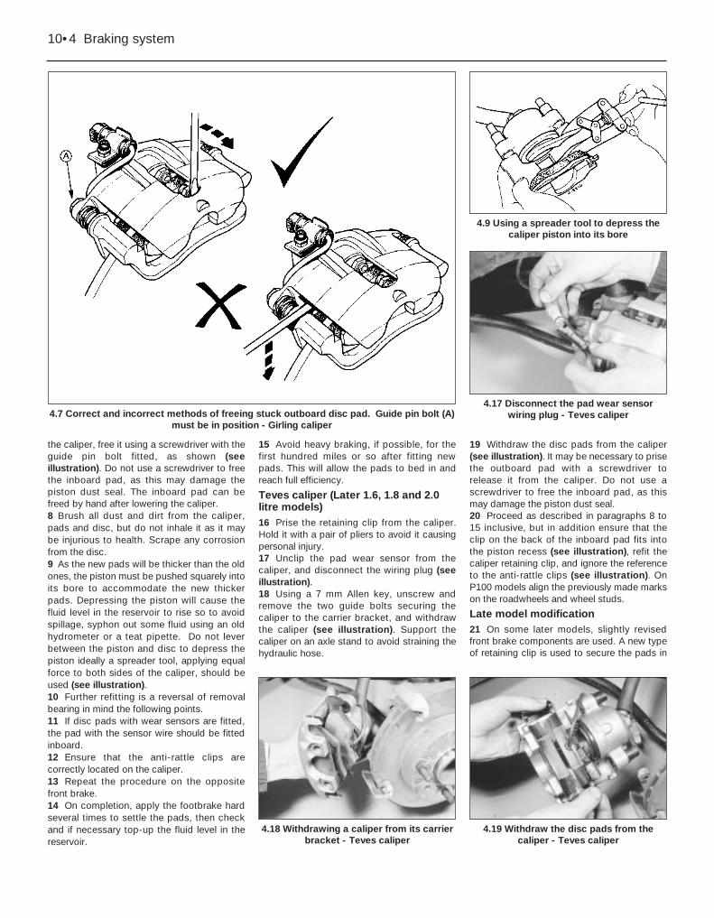
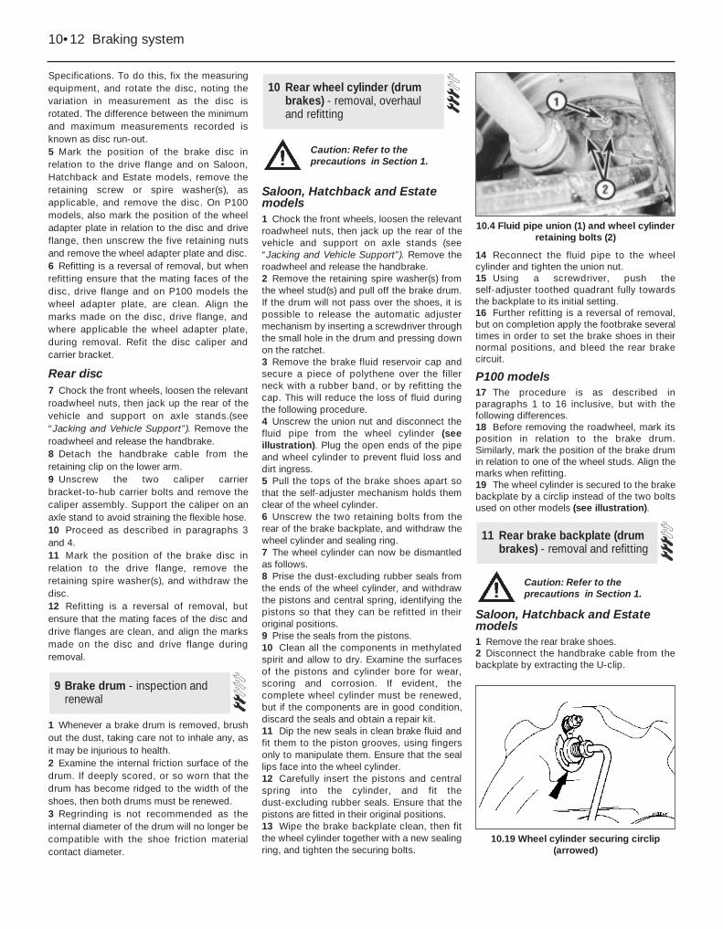
Teves caliper (Later 1.6, 1.8 and 2.0litre models)16 Prise the retaining clip from the caliper.Hold it with a pair of pliers to avoid it causingpersonal injury.17 Unclip the pad wear sensor from thecaliper, and disconnect the wiring plug (seeillustration).18 Using a 7 mm Allen key, unscrew andremove the two guide bolts securing thecaliper to the carrier bracket, and withdrawthe caliper (see illustration). Support thecaliper on an axle stand to avoid straining thehydraulic hose.
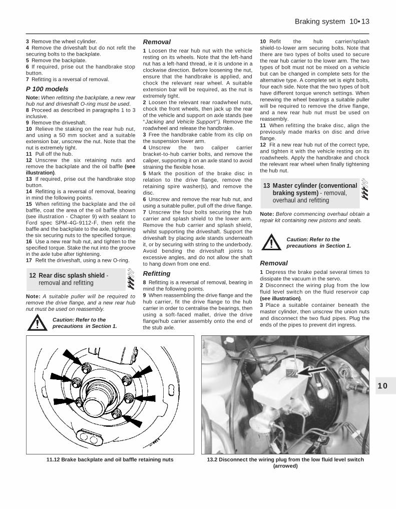
19 Withdraw the disc pads from the caliper(see illustration). It may be necessary to prisethe outboard pad with a screwdriver torelease it from the caliper. Do not use ascrewdriver to free the inboard pad, as thismay damage the piston dust seal.20 Proceed as described in paragraphs 8 to15 inclusive, but in addition ensure that theclip on the back of the inboard pad fits intothe piston recess (see illustration), refit thecaliper retaining clip, and ignore the referenceto the anti-rattle clips (see illustration). OnP100 models align the previously made markson the roadwheels and wheel studs.
Late model modification21 On some later models, slightly revisedfront brake components are used. A new typeof retaining clip is used to secure the pads in
10•4 Braking system
4.7 Correct and incorrect methods of freeing stuck outboard disc pad. Guide pin bolt (A)must be in position - Girling caliper
4.9 Using a spreader tool to depress thecaliper piston into its bore
4.19 Withdraw the disc pads from thecaliper - Teves caliper
4.18 Withdrawing a caliper from its carrierbracket - Teves caliper
4.17 Disconnect the pad wear sensorwiring plug - Teves caliper

the caliper, and the caliper body is modifiedaccordingly. Also, plastic covers are fitted tothe caliper guide bolts (see illustrations).22 Procedures are unchanged from thosegiven above.
Rear disc pads23 Slacken the rear roadwheel nuts, chockthe front wheels, then jack up the rear of thevehicle and support on axle stands. (see“Jacking and Vehicle Support”). Remove theroadwheel.24 The disc pads can be inspected throughthe top of the caliper after removal of theblanking spring clip. Check that the frictionmaterial thickness is not less than theminimum given in the Specifications.25 If any one of the pads has worn below thespecified limit, the rear pads must be renewed
as an axle set (4 pads).26 To renew the pads, proceed as follows.27 Release the handbrake, and free thehandbrake cable from the suspension lowerarm by bending back the tangs.28 Where applicable, disconnect the wiringto the disc pad wear sensor (see illustration).29 Unscrew and remove the bolt from theforward caliper guide pin, while holding thepin stationary with a spanner (seeillustration).30 Swing the caliper rearwards and lift outthe disc pads (see illustration). Do notdepress the brake pedal with the caliperremoved.31 Brush all dirt and dust from the caliper,pads and disc, but do not inhale it as it maybe injurious to health. Scrape any corrosionfrom the disc.
32 As the new pads will be thicker than theold ones, the piston must be retracted into itsbore to accommodate the new thicker pads.Retracting the piston will cause the fluid levelin the reservoir to rise, so to avoid spillage,syphon out some fluid using an oldhydrometer or a teat pipette. Retract thecaliper piston by turning it clockwise. Fordtool No 12-006 is designed for this purpose,but a pair of circlip pliers or any similar toolcan be used instead (see illustration).33 Remove the backing paper from the newpads, and fit them to the caliper.34 Further refitting is a reversal of removal,bearing in mind the following points.35 If disc pads with wear sensors are fitted,the pad with the sensor wire should be fittedinboard.36 Repeat the procedure on the oppositerear brake.37 On completion, switch on the ignition andapply the footbrake hard several times tosettle the pads. Switch off the ignition, thencheck and if necessary top-up the fluid level inthe reservoir. Check the operation of thehandbrake.38 Avoid heavy braking, if possible, for thefirst hundred miles or so after fitting newpads. This will allow the pads to bed in andreach full efficiency.
Braking system 10•5
10
4.21a Later type front disc pad retainingclip
4.32 Retracting the piston using circlippliers
4.30 Lift out the disc pads
4.28 Rear disc pad wear sensor wiring clip(arrowed)
4.29 Unscrewing the forward caliper guidepin bolt
4.21b Removing a caliper guide bolt cover- later type
4.20b Refitting the caliper retaining clip -Teves caliper
4.20a The clip on the back of the inboarddisc pad fits into the piston recess - Teves
caliper

1 The shoe friction material can be inspectedfor wear without removing the roadwheels.Working beneath the vehicle, prise the plugfrom the brake backplate, and using aninspection lamp or torch, check that thefriction material thickness is not less than theminimum given in the Specifications.2 If any one of the shoes has worn below thespecified limit, the shoes must be renewed asan axle set (4 shoes).3 To renew the shoes, slacken the rearroadwheel nuts, chock the front wheels, then
jack up the rear of the vehicle and support onaxle stands (see “Jacking and VehicleSupport”). Remove the rear roadwheels, andrelease the handbrake. On P100 models,mark the position of the roadwheels in relationto the brake drums before removal.4 Proceed as follows according to model:
1.3 and 1.6 litre models5 Remove the brake drum retaining spirewasher(s) from the wheel stud(s) and removethe brake drum. If the drum will not pass overthe shoes, it is possible to release theautomatic adjuster mechanism by inserting ascrewdriver through the small hole in the drumand pressing down on the ratchet (seeillustrations).6 Using a wire hook or a pair of long-nosedpliers, remove the top and bottom shoe returnsprings. Note the fitted positions of the
springs for reference when refitting (seeillustrations).7 Remove the hold-down cup, spring and pinfrom each shoe by depressing the cup andturning it through 90º (see illustration).8 Pull the bottom of the leading (front) shoetowards the front of the vehicle so that theself-adjuster ratchets separate, thendisengage the shoe from the strut by twistingit. Remove the shoe and adjuster mechanism.9 Pull the trailing (rear) shoe away from thebackplate far enough to gain access to thehandbrake cable. Disconnect the handbrakecable from the lever and remove the shoe withstrut and lever (see illustration).10 Clean and inspect all components, andlubricate the shoe contact points on thebackplate (see illustration). Take care not toinhale any dust, as it may be injurious tohealth.
5 Rear drum brake shoes- inspection and renewal
10•6 Braking system
5.5a Brake drum retaining spire washer(arrowed)
5.5c Drum removed showing screwdriverpressing on adjuster ratchet
5.6b Bottom shoe return spring
5.6a Top shoe return spring (arrowed)
5.5d Rear drum brake self-adjuster assembly - 1.3 and 1.6 litre models
A Shoe hold-down pointsB Trailing brake shoeC Self-adjuster strut and top return
springsD Wheel cylinderE Spring clips
F Self-adjuster strutG Leading brake shoeH Large ratchet segmentJ Small ratchet segmentK Brake backplate
5.5b Releasing the automatic adjusterusing a screwdriver
Caution: Refer to theprecautions in Section 1

11 Remove the strut from the trailing shoe byunhooking it from its spring. If a handbrakelever is not attached to the new shoe, removethe old lever by prising off the clip and drivingout the pin. Use a new clip on reassembly(see illustration).12 Similarly transfer the self-adjustercomponents to the new leading shoe. Notethat a small clearance (0.2 mm/0.008 in) mustexist between the underside of the smallerratchet segment and the brake shoe web.Insert feeler blades of the correct thicknessbeneath the ratchet when fitting the springclip, then withdraw the blades (seeillustration). The larger segment should befitted without any clearance.13 Commence reassembly by engaging theself-adjuster ratchet teeth as shown (seeillustration).14 Offer the trailing shoe to the backplate,fitting the handbrake cable to the handbrakelever and (if not already done) the strut andspring to the top of the shoe (seeillustration).15 Fit the leading shoe and adjustermechanism, engaging the hole in the adjusterwith the hook on the strut (see illustration).16 Fit the top and bottom return springs: thisis most easily done by allowing the ends ofthe shoe to pass in front of the wheel cylinderand the bottom pivot point, then engaging theshoes in their correct positions after thesprings have been fitted. Be careful not todamage the wheel cylinder rubber boots.
17 Fit and secure the hold-down pins,springs and cups.18 Back off the self-adjuster mechanism, bydepressing the lower (small) ratchet segment,to enable the brake drum to pass over theshoes. Centre the shoes relative to thebackplate.19 Refit the drum, making sure that the smallhole is in line with one of the two large holes inthe drive flange. Secure the drum by pushingthe spire washer(s) over the wheel stud(s).20 Have an assistant operate the footbrakeseveral times: a series of clicks should beheard from the drum as the self- adjustermechanism operates. When the clicking nolonger occurs, adjustment is complete.21 Renew the brake shoes on the other sideof the vehicle, then check the handbrakeadjustment.
22 Refit the roadwheels, lower the car andtighten the wheel nuts.23 Avoid harsh braking if possible for the firsthundred miles or so until the new linings havebedded in.
1.8 and 2.0 litre models24 Proceed as described in paragraph 5, buton P100 models mark the position of thebrake drum in relation to one of the wheelstuds (see illustration). 25 Remove the hold-down cup, spring andpin from the leading (front) shoe bydepressing the cup and turning it through 90º(see illustration).26 Note the fitted positions of the shoe returnsprings for reference when refitting, thenrelease the leading shoes from the wheelcylinder and the anchor bracket using ascrewdriver as a lever.
Braking system 10•7
10
5.10 Lubrication points on brake backplate
5.15 Engage the hole in the adjuster withthe hook on the strut (arrowed)
5.14 Strut and spring fitted to top of trailingshoe
5.13 Fully retract the self-adjuster ratchet(arrowed) before refitting the trailing shoe
5.12 Using feeler blades to set clearancebetween smaller ratchet segment andbrake shoe web. Spring clip arrowed
5.11 Handbrake lever-to-trailing shoesecuring clip (arrowed)
5.9 Disconnecting the handbrake cablefrom the trailing shoe lever
5.7 Using pliers to remove a shoe hold-down cup

27 Unhook the return springs and remove theleading shoe. Note the direction of wheelrotation arrows on the shoes.28 Remove the hold-down cup, spring andpin from the trailing (rear) shoe by depressingthe cup and turning it through 90º.29 Withdraw the trailing shoe and disconnect thehandbrake cable from the lever (see illustration).
30 Unhook the springs from the trailing shoeand remove the self-adjuster strut.31 Clean and inspect all components andlubricate the shoe contact points on thebackplate - refer to illustration, paragraph 10.Take care not to inhale any dust, as it may beinjurious to health.
32 Commence reassembly by fitting thesprings to the trailing shoe and attaching theself-adjuster strut.33 Attach the handbrake cable to the leverand position the trailing shoe on the wheelcylinder and anchor bracket. Ensure that theupper return spring is located on theself-adjuster strut.34 Refit the hold-down pin, spring and cup tothe trailing shoe.35 Connect the return springs to the leadingshoe, then locate the lower end in the anchorbracket and lever the upper end onto thetoothed quadrant lever and wheel cylinder. Becareful not to damage the wheel cylinderrubber boot.36 Refit the hold-down pin, spring and cup tothe leading shoe.37 Using a screwdriver, push theself-adjuster toothed quadrant fully towardsthe backplate to its initial setting.38 Proceed as described in paragraphs 19 to23 inclusive, but on P100 models, align thepreviously made marks on the brake drumsand wheel studs, and on the roadwheels andbrake drums.
Removal1 Apply the handbrake, loosen the relevantroadwheel nuts, then jack up the front of thevehicle and support on axle stands. (see“Jacking and Vehicle Support”). Remove theroadwheel. On P100 models, mark theposition of the roadwheel in relation to one ofthe wheel studs before removal.2 Remove the brake fluid reservoir cap andsecure a piece of polythene over the filler
6 Front disc caliper - removal,overhaul and refitting
10•8 Braking system
5.24 Exploded view of rear drum brake assembly - 1.8 and 2.0 litre models
A Leading brake shoeB Dust-excluding sealC PistonD Piston sealE Spring
F Wheel cylinder housingG BoltsH Hold-down pinJ Brake backplateK Adjuster plunger
L Trailing brake shoeM Self-adjuster strutN Hold-down spring and
cup
5.25 Leading shoe hold-down cup (arrowed) 5.29 Removing the trailing brake shoeA Handbrake cable and slot
Caution: Refer to theprecautions in Section 1.

neck with a rubber band, or by refitting thecap. This will reduce the loss of fluid duringthe following procedure.3 Disconnect the flexible fluid hose from therigid brake pipe under the wing of the vehicle,or alternatively unscrew the flexible hose fromthe union on the caliper. Take care not to twistthe hose, and plug the open ends to preventfluid loss and dirt ingress.4 Remove the disc pads.5 On models fitted with Girling calipers (1.3and early 1.6 litre models) (see illustration),unscrew and remove the bolt from the lowercaliper guide pin, while holding the pinstationary with a spanner, then remove thecaliper.6 On models fitted with Teves calipers (later1.6, 1.8 and 2.0 litre models) (seeillustration), remove the caliper from thevehicle.7 If required, the caliper carrier bracket canbe unbolted and removed from the hubcarrier.
Overhaul8 Brush away all external dirt and dust, buttake care not to inhale any dust as it may beinjurious to health.9 Pull the dust-excluding rubber seal from theend of the piston.10 Apply air pressure to the fluid inlet union,and eject the piston. Only low air pressure isrequired for this, such as is produced by afoot-operated tyre pump. Position a thin pieceof wood between the piston and caliper bodyto prevent damage to the end face of thepiston in the event of its being ejectedsuddenly.11 Using a suitable pointed instrument, prisethe piston seal from the groove in the cylinderbore. Take care not to scratch the surface ofthe bore.12 Clean the piston and caliper body withmethylated spirit and allow to dry. Examinethe surfaces of the piston and cylinder borefor wear, damage and corrosion. If the pistonsurface alone is unserviceable, a new pistonmust be obtained, along with seals. If thecylinder bore is unserviceable, the completecaliper must be renewed. The seals must berenewed regardless of the condition of theother components.13 Coat the piston and seals with cleanbrake fluid, then manipulate the piston sealinto the groove in the cylinder bore.14 Push the piston squarely into its bore.15 Fit the dust-excluding rubber sealbetween the piston and caliper, then depressthe piston fully.
Refitting16 Refit the caliper and where applicable thecarrier bracket by reversing the removaloperations. Tighten the mounting bolts to thespecified torque.
17 On P100 models, when refitting theroadwheel align the previously made markson the roadwheel and wheel stud.
18 On completion, bleed the front brakecircuit.
Braking system 10•9
10
6.6 Exploded view of Teves front disc caliper
A Guide boltsB Caliper carrier bracketC Caliper retaining clip
D Disc padsE Dust-excluding sealF Piston seal
G PistonH Caliper
6.5 Exploded view of Girling front disc caliper
A CaliperB Guide pin and dust
boot
C Piston sealD PistonE Dust-excluding seal
F Disc padsG Caliper carrier bracket

Note: Complete dismantling of the rear calipershould not be attempted unless Ford springcompressor (tool No 12-007) is available, orunless the problems likely to arise in theabsence of the tool are understood. Renewalof the piston seal dust-excluding seal andpiston adjuster nut seal requires no specialtools.
Removal1 With the ignition switched off, pump thebrake pedal at least 20 times, or until itbecomes hard, to depressurise the system.2 Chock the front wheels, slacken therelevant roadwheel nuts, then jack up the rearof the vehicle and support on axle stands (see“Jacking and Vehicle Support”). Remove theroadwheel and release the handbrake.3 Where applicable, disconnect the wiring tothe disc pad wear sensor.4 Proceed as described in Section 6,paragraphs 2 and 3, but note that the rigidbrake pipe is clipped to the suspension lowerarm.5 Unscrew and remove the two guide boltssecuring the caliper to the carrier bracket,while holding the pins with a spanner. Unhook
the handbrake cable from the lever, andwithdraw the caliper. Alternatively, the twocarrier bracket-to-hub carrier bolts can beunscrewed, and the caliper and carrier can beseparated on the bench, but in this case thehandbrake cable must be disconnected fromthe carrier bracket by removing the retainingcirclip.
Overhaul6 Clean the caliper, taking care not to inhaleany dust which may be injurious to health, andmount it in a soft-jawed vice.7 Rotate the piston anti-clockwise, usingFord tool No 12-006, or a pair of circlip pliersor similar tool, until it protrudes from thecaliper bore by approximately 20.0 mm (0.8in). Free the dust-excluding seal from thegroove in the piston, then continueunscrewing the piston and remove it. Removeand discard the dust-excluding seal.8 The piston and bore may now be cleanedand examined as described in Section 6,paragraph 12.9 The piston adjuster nut seal should berenewed as follows.10 Remove the circlip from the piston, thenextract the thrustwashers, wave washer andthrust bearing. Note the fitted sequence ofthese components. Finally remove the nut(see illustrations).11 Remove the seal from the nut, notingwhich way round it is fitted. Clean the nut withmethylated spirit. Lubricate the new seal withclean hydraulic fluid and fit it to the nut.
12 If no further dismantling is required,proceed to paragraph 20.13 For further dismantling it is virtuallyessential to have Ford tool 12-007 in order tocompress the adjuster spring. This toolappears to be a cut-down adjuster nut with ahandle for turning it. In the workshop it wasfound that the actual piston adjuster nut couldbe used to compress the spring if it wereturned with circlip pliers (see illustration).This works well enough for dismantling, butreassembly proved extremely difficultbecause of the limited clearance between theskirt of the nut and the caliper bore.14 Having compressed the adjuster springjust enough to take the load off the circlip,release the circlip inside the caliper bore.Remove the spring compressor, then extractthe circlip, spring cover, spring and washer(see illustrations).
7 Rear disc caliper - removal,overhaul and refitting
10•10 Braking system
7.10a Remove the circlip from the rearcaliper piston . . .
7.10c . . . a wave washer and (not shown)another thrustwasher . . .
7.14a Extract the circlip from the caliperbore . . .
7.13 Using the piston adjuster nut tocompress the adjuster spring
7.10e . . . and finally the adjuster nut itself.Note the seal (arrowed) on the nut
7.10d . . . then the thrust bearing . . .
7.10b . . . followed by the thrustwasher . . .
Caution: Refer to theprecautions in Section 1.

15 A long thin pair of circlip pliers will now berequired to release the key plate retainingcirclip from the caliper bore (see illustration).With the circlip removed, the pushrod and keyplate can be pulled out. 16 Remove the handbrake strut from thecaliper bore.17 Remove the handbrake lever return springand stop bolt. Pull the lever and shaft nut outof the caliper. Prise out the shaft seal (seeillustration).18 Clean the handbrake shaft using wirewool; renew the shaft if it is badly corroded.The shaft bush in the caliper can also berenewed if necessary. Pull out the old bushwith an internal puller or slide hammer, andpress in the new bush to 7.5 mm (0.30 in)below the shaft seal lip (see illustration). Theslot in the side of the bush must line up withthe pushrod bore in the caliper.
19 Having renewed components asnecessary, commence reassembly bysmearing a little brake grease or anti-seizecompound on the handbrake shaft and bush.20 Fit a new handbrake shaft seal to thecaliper. Pass the shaft through the seal andinto the caliper, taking care not to damage theseal lips.21 Refit the handbrake lever stop bolt andreturn spring.22 Refit the handbrake strut, lubricating itwith brake grease.23 Fit a new O-ring to the base of thepushrod. Refit the pushrod and the key plate,engaging the pip on the key plate with therecess in the caliper. Secure the key platewith the circlip.24 Refit the washer, spring and spring cover.Compress the spring and refit the circlip, thenrelease the spring compressor.25 Lubricate the caliper bore with cleanhydraulic fluid and fit a new piston seal.26 Reassemble the piston components.Lubricate the contact face of the adjuster nutwith a little brake grease, then fit the adjusternut (with new seal), thrust bearing,thrustwasher, wave washer and the secondthrustwasher. Secure with the circlip.27 Fit a new dust-excluding seal to thegrooves in the piston and caliper bore as thepiston is refitted (see illustration). Screw thepiston into the caliper bore with the tool usedduring removal.28 Renew the guide pin gaiters and apply alittle brake grease or anti-seize compound tothe guide pins when refitting the caliper to itscarrier bracket.
Refitting29 Refitting is a reversal of removal, but oncompletion bleed the rear brake circuit andcheck the operation of the handbrake.
Note: From 1987, thicker brake discs werefitted. If the later discs are fitted to earliermodels, longer wheel studs must be fitted toaccommodate the increased thickness.Consult a dealer for further advice.
Front disc1 Apply the handbrake, loosen the relevantroadwheel nuts, then jack up the front of thevehicle and support on axle stands (see“Jacking and Vehicle Support”). Remove theroadwheel.2 Remove the disc caliper and carrier bracketbut do not disconnect the flexible hose.Support the caliper on an axle stand to avoidstraining the flexible hose.3 Rotate the disc and examine it for deepscoring or grooving. Light scoring is normal,but if excessive, the disc should be removedand either renewed or reground by a suitablespecialist. Scrape any corrosion from the disc.4 Using a dial gauge or a flat metal block andfeeler blades, check that the disc run-outdoes not exceed the limit given in the
8 Brake disc - examination,removal and refitting
Braking system 10•11
10
7.14d . . . and the washer
7.27 Dust-excluding seal fitted to pistonand caliper bore
7.18 Handbrake shaft bush correctly fittedX = 7.5 mm (0.30 in)
7.17 Handbrake shaft and associatedcomponents
7.15 Remove the circlip (ends arrowed) torelease the pushrod and key plate
7.14c . . . the spring itself . . .7.14b . . . then the spring cover . . .
Caution: Refer to theprecautions in Section 1.
Specifications. To do this, fix the measuringequipment, and rotate the disc, noting thevariation in measurement as the disc isrotated. The difference between the minimumand maximum measurements recorded isknown as disc run-out.5 Mark the position of the brake disc inrelation to the drive flange and on Saloon,Hatchback and Estate models, remove theretaining screw or spire washer(s), asapplicable, and remove the disc. On P100models, also mark the position of the wheeladapter plate in relation to the disc and driveflange, then unscrew the five retaining nutsand remove the wheel adapter plate and disc.6 Refitting is a reversal of removal, but whenrefitting ensure that the mating faces of thedisc, drive flange and on P100 models thewheel adapter plate, are clean. Align themarks made on the disc, drive flange, andwhere applicable the wheel adapter plate,during removal. Refit the disc caliper andcarrier bracket.
Rear disc7 Chock the front wheels, loosen the relevantroadwheel nuts, then jack up the rear of thevehicle and support on axle stands.(see“Jacking and Vehicle Support”). Remove theroadwheel and release the handbrake.8 Detach the handbrake cable from theretaining clip on the lower arm.9 Unscrew the two caliper carrierbracket-to-hub carrier bolts and remove thecaliper assembly. Support the caliper on anaxle stand to avoid straining the flexible hose.10 Proceed as described in paragraphs 3and 4.11 Mark the position of the brake disc inrelation to the drive flange, remove theretaining spire washer(s), and withdraw thedisc.12 Refitting is a reversal of removal, butensure that the mating faces of the disc anddrive flanges are clean, and align the marksmade on the disc and drive flange duringremoval.
1 Whenever a brake drum is removed, brushout the dust, taking care not to inhale any, asit may be injurious to health.2 Examine the internal friction surface of thedrum. If deeply scored, or so worn that thedrum has become ridged to the width of theshoes, then both drums must be renewed.3 Regrinding is not recommended as theinternal diameter of the drum will no longer becompatible with the shoe friction materialcontact diameter.
Saloon, Hatchback and Estatemodels1 Chock the front wheels, loosen the relevantroadwheel nuts, then jack up the rear of thevehicle and support on axle stands (see“Jacking and Vehicle Support”). Remove theroadwheel and release the handbrake.2 Remove the retaining spire washer(s) fromthe wheel stud(s) and pull off the brake drum.If the drum will not pass over the shoes, it ispossible to release the automatic adjustermechanism by inserting a screwdriver throughthe small hole in the drum and pressing downon the ratchet.3 Remove the brake fluid reservoir cap andsecure a piece of polythene over the fillerneck with a rubber band, or by refitting thecap. This will reduce the loss of fluid duringthe following procedure.4 Unscrew the union nut and disconnect thefluid pipe from the wheel cylinder (seeillustration). Plug the open ends of the pipeand wheel cylinder to prevent fluid loss anddirt ingress.5 Pull the tops of the brake shoes apart sothat the self-adjuster mechanism holds themclear of the wheel cylinder.6 Unscrew the two retaining bolts from therear of the brake backplate, and withdraw thewheel cylinder and sealing ring.7 The wheel cylinder can now be dismantledas follows.8 Prise the dust-excluding rubber seals fromthe ends of the wheel cylinder, and withdrawthe pistons and central spring, identifying thepistons so that they can be refitted in theiroriginal positions.9 Prise the seals from the pistons.10 Clean all the components in methylatedspirit and allow to dry. Examine the surfacesof the pistons and cylinder bore for wear,scoring and corrosion. If evident, thecomplete wheel cylinder must be renewed,but if the components are in good condition,discard the seals and obtain a repair kit.11 Dip the new seals in clean brake fluid andfit them to the piston grooves, using fingersonly to manipulate them. Ensure that the seallips face into the wheel cylinder.12 Carefully insert the pistons and centralspring into the cylinder, and fit thedust-excluding rubber seals. Ensure that thepistons are fitted in their original positions.13 Wipe the brake backplate clean, then fitthe wheel cylinder together with a new sealingring, and tighten the securing bolts.
14 Reconnect the fluid pipe to the wheelcylinder and tighten the union nut.15 Using a screwdriver, push theself-adjuster toothed quadrant fully towardsthe backplate to its initial setting.16 Further refitting is a reversal of removal,but on completion apply the footbrake severaltimes in order to set the brake shoes in theirnormal positions, and bleed the rear brakecircuit.
P100 models17 The procedure is as described inparagraphs 1 to 16 inclusive, but with thefollowing differences.18 Before removing the roadwheel, mark itsposition in relation to the brake drum.Similarly, mark the position of the brake drumin relation to one of the wheel studs. Align themarks when refitting.19 The wheel cylinder is secured to the brakebackplate by a circlip instead of the two boltsused on other models (see illustration).
Saloon, Hatchback and Estatemodels1 Remove the rear brake shoes.2 Disconnect the handbrake cable from thebackplate by extracting the U-clip.
11 Rear brake backplate (drumbrakes) - removal and refitting
10 Rear wheel cylinder (drumbrakes) - removal, overhauland refitting
9 Brake drum - inspection andrenewal
10•12 Braking system
10.4 Fluid pipe union (1) and wheel cylinderretaining bolts (2)
10.19 Wheel cylinder securing circlip(arrowed)
Caution: Refer to theprecautions in Section 1.
Caution: Refer to theprecautions in Section 1.
3 Remove the wheel cylinder.4 Remove the driveshaft but do not refit thesecuring bolts to the backplate.5 Remove the backplate.6 If required, prise out the handbrake stopbutton.7 Refitting is a reversal of removal.
P 100 modelsNote: When refitting the backplate, a new rearhub nut and driveshaft O-ring must be used.8 Proceed as described in paragraphs 1 to 3inclusive.9 Remove the driveshaft.10 Relieve the staking on the rear hub nut,and using a 50 mm socket and a suitableextension bar, unscrew the nut. Note that thenut is extremely tight.11 Pull off the hub.12 Unscrew the six retaining nuts andremove the backplate and the oil baffle (seeillustration).13 If required, prise out the handbrake stopbutton.14 Refitting is a reversal of removal, bearingin mind the following points.15 When refitting the backplate and the oilbaffle, coat the area of the oil baffle shown(see illustration - Chapter 9) with sealant toFord spec SPM-4G-9112-F, then refit thebaffle and the backplate to the axle, tighteningthe six securing nuts to the specified torque.16 Use a new rear hub nut, and tighten to thespecified torque. Stake the nut into the groovein the axle tube after tightening.17 Refit the driveshaft, using a new O-ring.
Note: A suitable puller will be required toremove the drive flange, and a new rear hubnut must be used on reassembly.
Removal1 Loosen the rear hub nut with the vehicleresting on its wheels. Note that the left-handnut has a left-hand thread, ie it is undone in aclockwise direction. Before loosening the nut,ensure that the handbrake is applied, andchock the relevant rear wheel. A suitableextension bar will be required, as the nut isextremely tight.2 Loosen the relevant rear roadwheel nuts,chock the front wheels, then jack up the rearof the vehicle and support on axle stands (see“Jacking and Vehicle Support”). Remove theroadwheel and release the handbrake.3 Free the handbrake cable from its clip onthe suspension lower arm. 4 Unscrew the two caliper carrierbracket-to-hub carrier bolts, and remove thecaliper, supporting it on an axle stand to avoidstraining the flexible hose.5 Mark the position of the brake disc inrelation to the drive flange, remove theretaining spire washer(s), and remove thedisc.6 Unscrew and remove the rear hub nut, andusing a suitable puller, pull off the drive flange.7 Unscrew the four bolts securing the hubcarrier and splash shield to the lower arm.Remove the hub carrier and splash shield,whilst supporting the driveshaft. Support thedriveshaft by placing axle stands underneathit, or by securing with string to the underbody.Avoid bending the driveshaft joints toexcessive angles, and do not allow the shaftto hang down from one end.
Refitting8 Refitting is a reversal of removal, bearing inmind the following points.9 When reassembling the drive flange and thehub carrier, fit the drive flange to the hubcarrier in order to centralise the bearings, thenusing a soft-faced mallet, drive the driveflange/hub carrier assembly onto the end ofthe stub axle.
10 Refit the hub carrier/splashshield-to-lower arm securing bolts. Note thatthere are two types of bolts used to securethe rear hub carrier to the lower arm. The twotypes of bolt must not be mixed on a vehiclebut can be changed in complete sets for thealternative type. A complete set is eight bolts,four each side. Note that the two types of bolthave different torque wrench settings. Whenrenewing the wheel bearings a suitable pullerwill be required to remove the drive flange,and a new rear hub nut must be used onreassembly.11 When refitting the brake disc, align thepreviously made marks on disc and driveflange.12 Fit a new rear hub nut of the correct type,and tighten it with the vehicle resting on itsroadwheels. Apply the handbrake and chockthe relevant rear wheel when finally tighteningthe hub nut.
Note: Before commencing overhaul obtain arepair kit containing new pistons and seals.
Removal1 Depress the brake pedal several times todissipate the vacuum in the servo.2 Disconnect the wiring plug from the lowfluid level switch on the fluid reservoir cap(see illustration).3 Place a suitable container beneath themaster cylinder, then unscrew the union nutsand disconnect the two fluid pipes. Plug theends of the pipes to prevent dirt ingress.
13 Master cylinder (conventionalbraking system) - removal,overhaul and refitting
12 Rear disc splash shield -removal and refitting
Braking system 10•13
10
13.2 Disconnect the wiring plug from the low fluid level switch(arrowed)
11.12 Brake backplate and oil baffle retaining nuts
Caution: Refer to theprecautions in Section 1.
Caution: Refer to theprecautions in Section 1.
4 Unscrew the two mounting nuts and springwashers, and withdraw the master cylinderfrom the servo. Cover the master cylinder withrag or a plastic bag to prevent spillage ofhydraulic fluid on the vehicle paintwork. If fluidis accidentally spilt on the paintwork, wash offimmediately with cold water.
Overhaul5 Drain the remaining fluid from the mastercylinder, and clean the exterior surfaces withmethylated spirit.6 Pull the fluid reservoir from the top of themaster cylinder and prise out the sealingrubbers (see illustration).7 Mount the master cylinder in a vice, thendepress the primary piston slightly and extractthe circlip and washer. Withdraw the primarypiston assembly.8 Depress the secondary piston and removethe stop pin from the fluid aperture.9 Remove the master cylinder from the viceand tap it on the bench to remove thesecondary piston assembly.10 Prise the seals from the secondary piston.Do not attempt to dismantle the primarypiston.11 Clean all the components in methylatedspirit and examine them for wear anddamage. In particular check the surfaces ofthe pistons and cylinder bore for scoring andcorrosion. If the cylinder bore is worn, renewthe complete master cylinder, otherwiseobtain a repair kit including pistons and seals.12 Check that the fluid inlet and outlet portsare free and unobstructed. Dip the newpistons and seals in clean brake fluid.13 Fit the seals to the secondary piston usingthe fingers only to manipulate them into thegrooves. Note that the sealing lips must faceaway from each other.14 Insert the secondary piston and springinto the cylinder. Turn the piston slowly as thefirst seal enters to avoid trapping the sealinglip. Similarly insert the primary piston andspring, then fit the washer and circlip.15 Depress the primary and secondarypistons and refit the secondary piston stoppin.16 Fit the fluid reservoir sealing rubbers and
press the reservoir into them. If the rubbersare worn or perished, or if leakage has beenevident, fit the new rubbers.
Refitting17 Refitting is a reversal of removal buttighten the mounting nuts and pipe union nutsto the specified torque and finally bleed thehydraulic system.
Removal1 To remove the servo, first remove themaster cylinder.2 Disconnect the vacuum hose from theservo (see illustration).3 Working inside the vehicle, remove thelower facia panel from the driver’s side.4 Remove the clip from the servo pushrod onthe brake pedal (see illustration). 5 Unscrew the two mounting nuts andwashers securing the servo to the bulkhead,and lift the servo from the bulkhead. Note thatthe two mounting nuts also secure the pedalbracket to the bulkhead.
6 If required, the vacuum hose can bedisconnected from the inlet manifold, and thenon-return valve can be checked for correctoperation by ensuring that it is only possibleto blow through it in one direction.7 No overhaul of the servo is possible, and iffaulty, it must be renewed as a complete unit.
Refitting8 Refitting is a reversal of removal, but whenrefitting the servo to the bulkhead, ensure thatthe pushrod is correctly located in the pedaland that the clip is secure.
Vacuum hose - modification9 From mid-1989, a new type of brake servovacuum hose-to-inlet manifold connector hasbeen used in production. The connectorcomprises three parts; a collet which locksthe hose in position, an O-ring, and a brassinsert which is pressed into the inlet manifold.10 To disconnect the hose from the inletmanifold, apply light even pressure, push andhold the flange of the collet against themanifold. While holding the collet forward,gently pull the hose from the collet (seeillustration). Take care not to pull at an angleor use excessive force, as this can cause thecollet to snatch and lock the hose.11 To reconnect the hose, push the hose intothe collet until the swage on the hose is hardagainst the collet flange. Pull gently on thehose to check that it is locked by the collet.
14 Vacuum servo (conventionalbraking system) - removal andrefitting
10•14 Braking system
14.10 Disconnecting a later-type brakeservo vacuum hose
14.4 Remove the clip (arrowed) from theservo pushrod
14.2 Servo vacuum hose non-return valve(A) and servo connection (B) - conventional
braking system
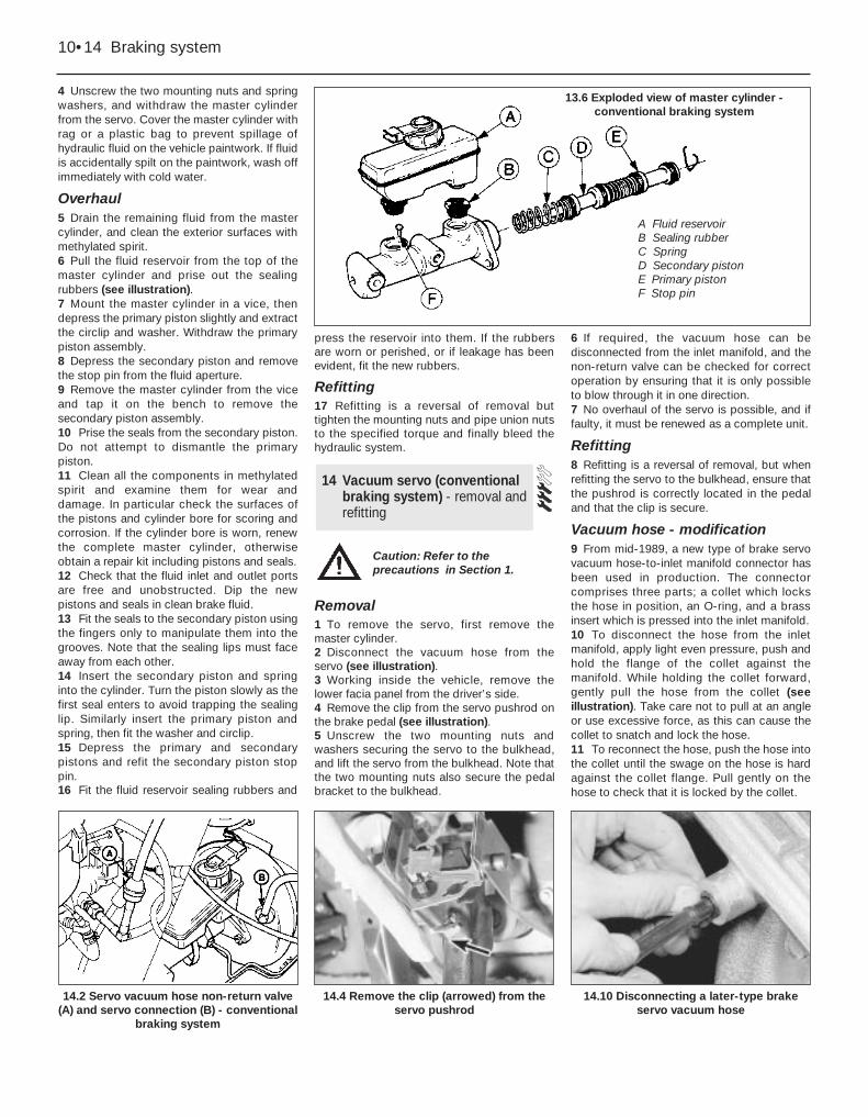
13.6 Exploded view of master cylinder -conventional braking system
A Fluid reservoirB Sealing rubberC SpringD Secondary pistonE Primary pistonF Stop pin
Caution: Refer to theprecautions in Section 1.

Note: New seals must be used between thereservoir and the hydraulic unit on reassembly.
Removal1 Disconnect the battery negative lead.2 Depressurise the hydraulic system bypumping the brake pedal at least 20 times, oruntil it becomes hard.3 Disconnect the wiring multi-plugs from thereservoir cap and remove the cap.4 Unscrew the reservoir securing screw, andremove the securing clip, noting that the clipalso supports the clutch cable (see illustration).
5 Prepare a suitable container to collect thefluid as the hydraulic unit is drained, thenremove the securing spring clip anddisconnect the low pressure fluid hose fromthe pump (see illustrations). Allow the fluid todrain out of the hose into the container. If fluidis accidentally spilt on the paintwork, wash offimmediately with cold water.6 Pull the reservoir out of the seals on thehydraulic unit and remove it (see illustration).7 Note the spigot locating bush on the rearhydraulic unit inlet, which may stay in thehydraulic unit or may come out with thereservoir (see illustration).
Refitting8 Refitting is a reversal of removal, but usenew seals between the reservoir and thehydraulic unit.9 On completion, bleed the completehydraulic system and check for leaks aroundall disturbed components.
Note: A new gasket must be used betweenthe hydraulic unit and the bulkhead onrefitting.
Removal1 Disconnect the battery negative lead.2 Depressurise the hydraulic system bypumping the brake pedal at least 20 times, oruntil it becomes hard.3 Disconnect the six multi-plugs from thehydraulic unit. They are all different, so thereis no need to label them. When a plug has aspring clip retainer, lift the clip before pullingout the plug. To release the pump plug, pullback the rubber boot and the plug sleeve (seeillustrations).4 Unbolt the earth strap from the unit.5 Prepare a suitable container to catch spiltfluid. Mark the hydraulic pipes so that theycan be refitted in their original positions, thendisconnect them from the base of the unit.Plug the open ends of the pipes and hydraulicunit to prevent fluid leakage and dirt ingress. Iffluid is accidentally spilt on the paintwork,wash off immediately with cold water.6 Working inside the vehicle, remove thelower facia panel from the driver’s side.
16 Hydraulic unit (ABS)- removal and refitting
15 Fluid reservoir (ABS)- removal and refitting
Braking system 10•15
10
15.5b . . . and disconnect the low pressurefluid hose - ABS
16.3c . . . and the pressure switch multi-plug - ABS
16.3b . . . the main valve multi-plug . . .16.3a Disconnecting the low fluid levelswitch multi-plug . . .
15.7 Removing the spigot locating bushfrom the rear hydraulic unit inlet - ABS
15.6 Removing the fluid reservoir from thehydraulic unit - ABS
15.5a Remove the securing spring clip . . .15.4 Reservoir securing clip (arrowed) alsosupports clutch cable - ABS
Caution: Refer to theprecautions in Section 1.
Caution: Refer to theprecautions in Section 1.
7 Remove the clip from the hydraulic unitpushrod on the brake pedal. 8 With an assistant supporting the hydraulicunit, unscrew the four nuts which secure theunit to the bulkhead (see illustration).Withdraw the unit from under the bonnet.9 Recover the gasket fitted between the unitand the bulkhead.10 Drain the fluid from the reservoir. Do notactuate the pushrod with the unit removed.11 Dismantling of the hydraulic unit shouldbe limited to the operations described in thefollowing Sections (see illustration).
Refitting12 Refitting is a reversal of removal, bearingin mind the following points.
13 Do not refill the fluid reservoir untilreassembly and refitting is complete.14 Use a new gasket between the hydraulicunit and the bulkhead.15 Ensure that the hydraulic pipes arereconnected to the correct unions.16 On completion, bleed the completehydraulic system and check for leaks aroundall disturbed components.
Note: A new O-ring must be used betweenthe accumulator and the hydraulic unit onrefitting.
Removal1 Disconnect the battery negative lead. 2 Depressurise the hydraulic system bypumping the brake pedal at least 20 times, oruntil it becomes hard. 3 Wrap a clean rag round the base of theaccumulator to catch any spilt fluid. 4 Unscrew the accumulator using a hexagonkey. Remove the accumulator, noting thesealing ring and being prepared for fluidspillage (see illustration). If fluid is
accidentally spilt on the paintwork, wash offimmediately with cold water.
Refitting5 Fit a new O-ring to the base of theaccumulator, fit the accumulator and tightenit.6 Reconnect the battery. Switch on theignition and check that the hydraulic unitpump stops within 60 seconds; if not, theaccumulator is likely to be faulty.7 On completion, bleed the completehydraulic system and check for leaks aroundall disturbed components.
Note: New sealing washers must be used onthe high pressure fluid hose banjo union, anda new O-ring must be used between theaccumulator and the hydraulic unit on refitting.
Removal1 Remove the accumulator.2 Prepare a suitable container to catch spiltfluid, and disconnect the high pressure fluidhose from the pump.3 Remove the securing spring clip anddisconnect the low pressure fluid hose fromthe pump. Allow the fluid to drain out of thehose into the container. If fluid is accidentallyspilt on the paintwork, wash off immediatelywith cold water.4 Disconnect the multi-plugs from thepressure switch and the pump motor.5 Remove the pump mounting bolt (seeillustration).6 Pull the pump and motor assembly off themounting spigot and remove it.7 Recover the mounting bushes and renewthem if necessary.8 If a new pump is to be fitted, transfer thepressure switch to it, using a new O-ring.
18 Hydraulic unit pump and motor(ABS) - removal and refitting
17 Hydraulic unit accumulator(ABS) - removal and refitting
10•16 Braking system
16.8 Hydraulic unit-to-bulkhead securingnuts (arrowed) - ABS
17.4 Unscrew the accumulator and removeit, noting the O-ring (arrowed)
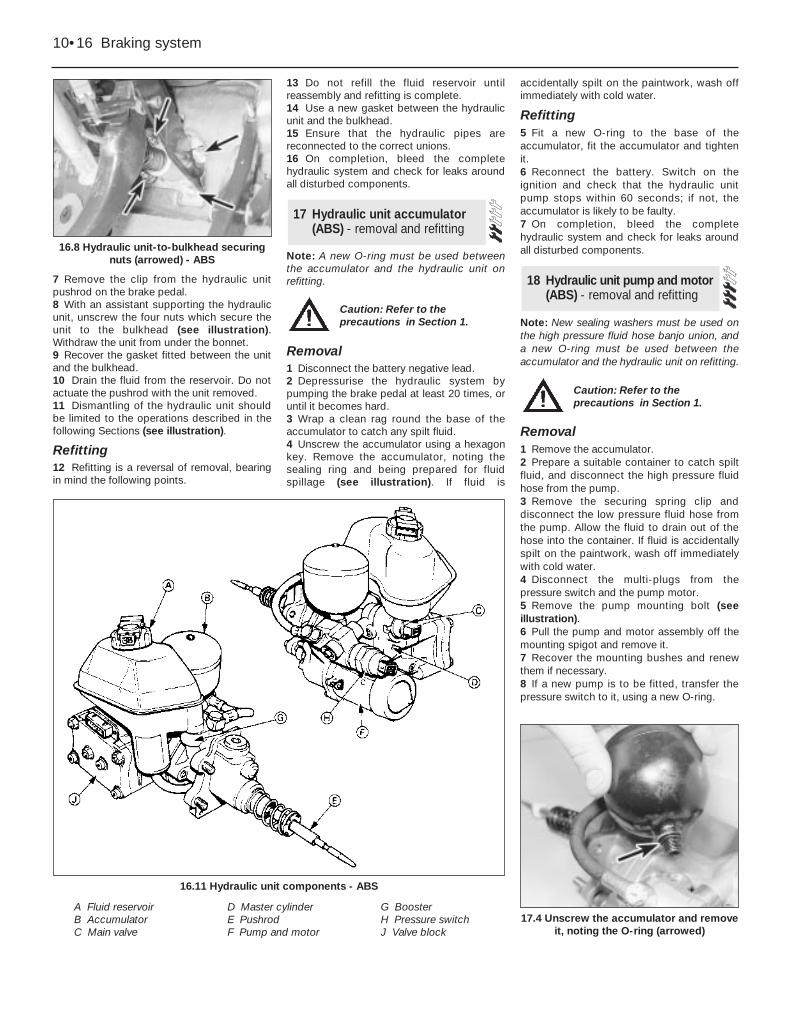
16.11 Hydraulic unit components - ABS
A Fluid reservoirB AccumulatorC Main valve
D Master cylinderE PushrodF Pump and motor
G BoosterH Pressure switchJ Valve block
Caution: Refer to theprecautions in Section 1.
Caution: Refer to theprecautions in Section 1.

Refitting9 Commence refitting by offering the pump tothe mounting spigot, then reconnecting thelow pressure fluid hose.10 Refit and tighten the pump mounting bolt.11 Reconnect the high pressure fluid hose,using new sealing washers on the banjounion.12 Refit the accumulator, using a new O-ring.13 Reconnect the multi-plugs and thebattery.14 Refill the fluid reservoir, then switch on theignition and allow the pump to prime itself.Allow the pump to run for a maximum of twominutes at a time then leave it for ten minutesto cool down.15 On completion, bleed the completehydraulic system and check for leaks aroundall disturbed components.
Note: To remove the pressure switch from thehydraulic unit in situ, Ford tool No 12-008 or alocally made equivalent will be required. Theswitch may be removed without special toolsafter removing the hydraulic unit complete orthe pump above. A new O-ring must be usedwhen refitting the switch.
Removal1 Disconnect the battery negative lead.2 Depressurise the hydraulic system bypumping the brake pedal at least 20 times, oruntil it becomes hard.3 Disconnect the multi-plug from the switch,then unscrew and remove the switch.
Refitting4 Refit the switch using a new O-ring.Position the plastic sleeve so that the drainhole faces the pump motor, then tighten theswitch (see illustration).5 Reconnect the multi-plug and the battery.6 On completion, bleed the completehydraulic system and check for leaks aroundall disturbed components.
Removal1 Disconnect the battery negative lead.2 Depressurise the hydraulic system bypumping the brake pedal at least 20 times, oruntil it becomes hard.3 Apply the handbrake, and slacken theleft-hand front wheel nuts. Jack up the front ofthe vehicle and support on axle stands (see“Jacking and Vehicle Support”).Remove theleft-hand front wheel.4 Remove the plastic liner from under thewheel arch.5 Prepare a suitable container to catch spiltfluid, clean around the unions on the valveblock, then unscrew and disconnect the fluidpipes (see illustration). Plug the open ends ofthe pipes and valve block to prevent fluidleakage and dirt ingress. If fluid is accidentallyspilt on the paintwork, wash off immediatelywith cold water. 6 Disconnect the multi-plug and the earthstrap from the valve block. 7 Working through the wheel arch, unscrewthe three nuts which secure the valve blockmounting bracket (see illustration).
8 Remove the valve block and mountingbracket, taking care not to spill brake fluid onthe paintwork.9 No further dismantling of the valve block ispossible, but the pressure regulating valve inthe rear brake pipe union can be renewed ifdesired.
Refitting10 Refitting is a reversal of removal.11 On completion, bleed the completehydraulic system and check for leaks aroundall disturbed components.
Removal1 Disconnect the battery.2 Working inside the vehicle, prise out thefacia trim panel from the passenger’s side.Remove the insulation.3 To remove the now exposed module, pushit as necessary to release the retaining catch.
21 Computer module (ABS)- removal and refitting
20 Valve block (ABS) - removaland refitting
19 Hydraulic unit pressure switch(ABS) - removal and refitting
Braking system 10•17
10
20.5 Valve block and associatedcomponents - ABS
A Bracket screwsB Adapter plateC valve block
D Multi-plugE Earth strap
anchor point
19.4 Refit the pressure switch with thedrain hole (arrowed) in the plastic sleeve
facing the pump motor - ABS
18.5 Hydraulic unit pump mounting bolt -ABS
20.7 Unscrewing the valve block mountingbracket nuts (arrowed) - ABS
Caution: Refer to theprecautions in Section 1.
Caution: Refer to theprecautions in Section 1.

4 Withdraw the module, and disconnect themulti-plug (see illustration).
Refitting5 Refitting is a reversal of removal but oncompletion check the operation of the ABSwarning lamp as described in themanufacturer’s handbook.
Note: A new O-ring must be used whenrefitting a sensor.
Front wheel sensor1 Apply the handbrake, loosen the relevantfront roadwheel nuts, then jack up the front ofthe vehicle and support on axle stands (see“Jacking and Vehicle Support”). Remove theroadwheel.2 Working under the bonnet, unclip the ABSwiring loom from the chassis side member,and disconnect the wheel sensor wiring plug.3 Unscrew the mounting bolt and withdrawthe sensor (see illustration).4 Refitting is a reversal of removal, bearing inmind the following points.5 Clean the bore in the hub carrier, and smearthe bore and the sensor with lithium basedgrease.6 Use a new O-ring seal when refitting thesensor.
Rear wheel sensor7 Chock the front wheels, loosen the relevantrear roadwheel nuts, then jack up the rear ofthe vehicle and support on axle stands.Release the handbrake and remove theroadwheel.8 Working inside the vehicle, lift up the rearseat cushion, then remove the side kick paneland fold the carpet forwards to gain access tothe wheel sensor wiring plug (seeillustrations).9 Remove the wiring plug from its clip, anddisconnect it.10 Prise out the floor panel grommet, thenfeed the sensor wiring through the floor panel.11 Free the handbrake cable from its clip onthe suspension lower arm.
12 Where applicable, disconnect the wiringto the disc pad wear sensor.13 Unscrew and remove the bolt from theforward caliper guide pin, while holding thepin stationary with a spanner.14 Swing the caliper rearwards to gainaccess to the wheel sensor. 15 Unscrew the bolt securing the sensor toits mounting bracket.16 Refitting is a reversal of removal, bearingin mind the following points.17 Clean the bore in the sensor mountingbracket, and smear the bore and the sensorwith lithium based grease.18 Use a new O-ring seal when refitting thesensor.
Removal1 The deceleration sensitive valve is locatedon the left-hand side of the enginecompartment (see illustrations).2 Place a suitable container beneath thevalve to catch spilt fluid, then unscrew theunion nuts and disconnect the fluid pipes.
Plug the open ends of the pipes and valve toprevent fluid leakage and dirt ingress. If fluid isaccidentally spilt on the paintwork, wash offimmediately with cold water.3 On early models, the valve is secured to themounting bracket on the inner wing by asingle bolt. Unscrew the bolt and remove thevalve. 4 On later models, the valve is secured to themounting bracket by a clip. Remove the clipand slide out the valve.
Refitting5 Refitting is a reversal of removal, but notethat the early type of valve must be fitted withthe cover bolts facing forwards, and the latertype of valve must be fitted with the smallerdiameter stepped end facing forwards.6 On completion, bleed the rear hydrauliccircuit.
23 Deceleration sensitive valve(all models with conventionalbraking system)- removal and refitting
22 Wheel sensor (ABS)- removal and refitting
10•18 Braking system
21.4 Withdraw the module and disconnectthe multi-plug - ABS
22.8a Remove the side kick panel(securing screws arrowed) for access tothe rear wheel sensor wiring plug - ABS
23.1b Later type deceleration sensitivevalve
23.1a Early type deceleration sensitivevalve
22.8b Rear wheel sensor wiring plug(arrowed) - ABS
22.3 Unscrew the mounting bolt andwithdraw the front wheel sensor - ABS
Caution: Refer to theprecautions in Section 1.

Removal1 Chock the front wheels, jack up the rear ofthe vehicle and support on axle stands (see“Jacking and Vehicle Support”).2 The load apportioning valve is located onthe right-hand side of the vehicle underbodyabove the axle.3 Remove the spring clip and clevis pin, anddetach the spring from the valve operatinglever (see illustration).4 Place a suitable container beneath thevalve to catch spilt fluid, then unscrew theunion nuts and disconnect the fluid pipes.Plug the open ends of the pipes and valve toprevent fluid leakage and dirt ingress.5 Unscrew the three securing nuts and boltsfrom the valve mounting bracket, and removethe valve assembly (see illustration).
Refitting6 Refitting is a reversal of removal, but notethat the fluid inlet pipe from the master cylinder
must be connected to the lower valve port, andthe fluid outlet pipe to the rear brakes must beconnected to the upper valve port.7 On completion, bleed the rear hydrauliccircuit and check the valve adjustment.
Models before mid-April 19891 The vehicle must be unladen, at normalkerb weight (a full tank of petrol, but no driveror load).2 With the vehicle standing on its roadwheels,remove the spring clip and clevis pin, anddetach the spring from the valve operatinglever.3 Loosen the locknut on the abutment blockat the bottom of the spring (see illustration).4 Slide the spring through the grommet in thebracket on the axle, until the correct “X”dimension is obtained between the centre ofthe spring eye and the centre of the valveoperating lever eye (see illustration).5 Hold the spring in position, slide theabutment block against the underside of thegrommet, and tighten the locknut.6 Attach the free end of the spring to thevalve operating lever, and refit the clevis pinand spring clip.
Models from mid-April 19897 The procedure is as described above, butnote that the dimension “X” has been revisedto 92.0 mm (3.6 in) with the vehicle unladen atnormal kerb weight.
Removal1 To remove a flexible hose, always free itfrom any mounting bracket(s) first by prisingout the U-shaped retaining clip, and thenusing two close-fitting spanners to disconnectthe hose-to-rigid pipe union (see illustration).2 Once disconnected from the rigid pipe, theflexible hose may be unscrewed from thecaliper or wheel cylinder union, as applicable.
Refitting3 When reconnecting pipe or hose fittings,note that the seal is made at the swaged endof the pipe, so do not continue to tighten aunion if it is tight, yet still stands proud of thesurface into which it is screwed.
26 Brake fluid pipes and hoses- removal and refitting
25 Load apportioning valve(P100 models) - adjustment
24 Load apportioning valve(P100 models) - removal andrefitting
Braking system 10•19
10
25.3 Loosen the locknut (arrowed) on theabutment block
26.1 Flexible hose-to-rigid pipe union. U-shaped retaining cliparrowed
25.4 Load apportioning valve adjustmentX = 77.0 mm (3.0 in) with vehicle unladen at normal kerb weight
24.5 Load apportioning valve securingbolts (arrowed)
24.3 Remove the spring clip (arrowed) andclevis pin from the valve operating lever
Caution: Refer to theprecautions in Section 1.
Caution: Refer to theprecautions in Section 1.

4 A flexible hose must never be installedtwisted, but a slight “set” is permissible togive it clearance from adjacent components.This can be achieved by turning the hoseslightly before fitting the U-shaped retainingclip to the mounting bracket.5 Rigid pipelines can be made to pattern bymotor factors supplying brake components.
Removal1 Chock the front wheels, loosen the rearroadwheel nuts, then jack up the rear of thevehicle and support on axle stands. Releasethe handbrake and remove the roadwheels.2 Slacken the handbrake cable adjuster.3 Extract the securing circlip and pivot pin,and detach the handbrake equaliser from thelinkage on the underbody (see illustration).
4 On models with a conventional brakingsystem, remove the brake shoes anddisconnect the handbrake cables from theoperating levers, then disconnect the cablesfrom the brake backplates by extracting theU-clips.5 On models with ABS, unhook thehandbrake cables from the operating leverson the calipers, then disconnect the cablesfrom the caliper carrier brackets by removingthe retaining circlips (see illustrations).6 On Saloon, Hatchback and Estate modelsbend back the tangs and release the cablesfrom the lower suspension arms, then feedthe cables through the holes in thesuspension crossmember and release themfrom the brackets on the underbody, notingthat the right-hand cable is retained by acirclip (see illustration). Withdraw the cableassembly from the vehicle.7 On P100 models, release the cables fromthe brackets on the chassis crossmember,noting that the left-hand cable is retained by acirclip, then unhook the cable support springs
and withdraw the cable assembly from thevehicle (see illustration).
Refitting8 Refitting is a reversal of removal. Onmodels with a conventional braking systemrefit the brake shoes. 9 On completion, adjust the cable.
27 Handbrake cable - removaland refitting
10•20 Braking system
27.3 Handbrake equaliser securing circlip(arrowed) and pivot pin
27.5b Handbrake cable-to-caliper carrier bracket attachment -ABS
27.7 Handbrake cable support spring (arrowed)27.6 Handbrake cable-to-lower suspension arm attachment
27.5a Handbrake cable-to-operating lever attachment - ABS

Note: Where fitted, the adjuster locking pinmust be renewed on completion ofadjustment.
Conventional braking system(except P100 models)1 The handbrake cable is normallyself-adjusting in use, however adjustmentmay be required to compensate for cablestretch over a long period, and is alsonecessary after fitting a new cable.2 Chock the front wheels, jack up the rear ofthe vehicle and support on axle stands (see“Jacking and Vehicle Support”). Release thehandbrake.3 Unscrew the locknut from the adjusterlocated on the left-hand underbody bracket(see illustration). On later models, a lockingpin is fitted to the bracket to lock the adjusternuts in position. Where applicable, remove thelocking pin before unscrewing the locknut.
4 Apply the footbrake vigorously severaltimes to set the self-adjuster mechanism.5 Turn the adjuster until the plastic plungerslocated in the brake lockplates are free toturn, and the total movement of both plungersadded together is between 0.5 and 1.0 mm(0.02 and 0.04 in) (see illustration).6 Tighten the adjuster locknut against theadjuster nut by hand (two clicks), then tightenfurther by a minimum of two and a maximumof four clicks, using a suitable spanner orpliers.7 Where applicable, fit a new adjuster lockingpin. The old pin should not be re-used.8 Check that with the handbrake released,the rear wheels are free to rotate and no brake“bind” is evident. The handbrake lever travelshould be between two and four clicks of theratchet. If brake “bind” or excessive levertravel is evident, check the handbrake cablerouting, and check the self-adjustermechanism for wear or damage.
ABS9 Proceed as described in paragraphs 1 to 3inclusive.10 Bend back the tangs and release thecables from the lower suspension arms.11 Ensure that both handbrake operatinglevers are returned to their stops on thecalipers, then make alignment marks betweenthe levers and the caliper bodies (seeillustration).12 Turn the adjuster until either lever juststarts to move, as indicated by the alignmentmarks.13 Apply the handbrake and release itseveral times to equalise the cable runs.14 With the handbrake released, proceed asdescribed in paragraphs 6 and 7.15 Refit the cables to the lower suspensionarms, and secure by bending over the tangs.16 Check that with the handbrake released,the rear wheels are free to rotate and no brake
“bind” is evident. The handbrake lever travelshould be between two and four clicks of theratchet. If brake “bind” or excessive levertravel is evident, check the handbrake cablerouting, and check the caliper mechanism forwear or damage.
P100 models17 Proceed as described in paragraphs 1 to4 inclusive, but note that the adjuster islocated on the right-hand side of the chassiscrossmember (see illustration).18 Apply the handbrake, pulling the leverupwards three clicks.19 Turn the adjuster until both rear wheelsare locked and cannot be turned by hand.20 Proceed as described in paragraphs 6and 7.21 Check that with the handbrake released,the rear wheels are free to rotate and no brake“bind” is evident. The handbrake lever travelshould be between three and five clicks of theratchet. If brake “bind” or excessive levertravel is evident, check the handbrake cablerouting, and check the self-adjustermechanism for wear or damage.
28 Handbrake cable - adjustment
Braking system 10•21
10
28.5 Plastic plunger (arrowed) in brake backplate
28.17 Handbrake cable adjuster on right-hand side of chassis crossmember
28.11 Make alignment marks betweeneach handbrake operating lever and
caliper body (arrowed) - ABS
28.3 Handbrake cable adjuster on left-hand underbody bracket(arrowed)

Removal1 Chock the rear wheels, jack up the front ofthe vehicle and support on axle stands.Release the handbrake. Disconnect thebattery negative lead.2 Slacken the handbrake cable adjuster. 3 Extract the securing circlip and pivot pin,and detach the handbrake equaliser from thelinkage on the underbody (see illustration). 4 Working inside the vehicle, remove thehandbrake lever rubber gaiter and/or thecentre console, as necessary. 5 Disconnect the wiring connector from thehandbrake “on” warning switch.
6 Unscrew the two handbrake lever mountingbolts, and carefully lift the lever through theunderfloor gaiter. 7 If required, the handbrake “on” warningswitch can be removed.
Refitting 8 Refitting is a reversal of removal, but oncompletion, adjust the handbrake cable.
Removal1 Remove the clutch pedal as described inChapter 6.2 Extract the inboard circlip from the brakepedal end of the pivot shaft (see illustration).
3 The brake pedal can now be removed fromthe pedal bracket by sliding out the pivotshaft, noting the position of any washers andspacers which may be fitted.4 If desired, the nylon bushes can be prisedfrom each side of the pedal for renewal, andthe brake lamp switch removed.
Refitting5 Refitting is a reversal of removal, fitting anywashers and spacers in their originalpositions. Refit the clutch pedal.
30 Brake pedal - removal andrefitting
29 Handbrake lever - removaland refitting
10•22 Braking system
29.3 Handbrake equaliser and linkage on underbody 30.2 Extract the inboard circlip (arrowed) to remove the pedalpivot shaft


![REGENERATIVE BRAKING SYSTEM IN ELECTRIC VEHICLES · REGENERATIVE BRAKING SYSTEM IN ELECTRIC VEHICLES ... REGENERATIVE BRAKING SYSTEM ... Regenerative action during braking[9].](https://static.fdocuments.us/doc/165x107/5adccef67f8b9a1a088c7cf0/regenerative-braking-system-in-electric-vehicles-braking-system-in-electric-vehicles.jpg)