1 WAN Basics. 2 Agenda WAN Basics Point-to-Point Protocol (PPP) Integrated Services Digital Network...
41
1 WAN Basics
-
Upload
bethany-dorcas-osborne -
Category
Documents
-
view
223 -
download
0
Transcript of 1 WAN Basics. 2 Agenda WAN Basics Point-to-Point Protocol (PPP) Integrated Services Digital Network...
1
WAN Basics
2
Agenda
WAN Basics Point-to-Point Protocol (PPP) Integrated Services Digital
Network (ISDN) Frame Relay
3
WAN Basics
4
A network that serves users across a broad geographic area
Often uses transmission devices provided by public carriers (Pacific Bell, AT&T, etc.) This service is commonly referred to as “plain
old telephone service” (POTS) WANs function at the lower three layers of the
OSI reference model Physical layer, data link layer, and network layer
What Is a WAN?
5
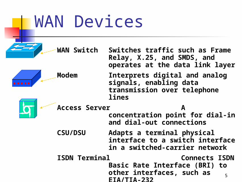
WAN Devices
WAN Switch Switches traffic such as Frame Relay, X.25, and SMDS, and operates at the data link layer
Modem Interprets digital and analog signals, enabling data transmission over telephone lines
Access Server A concentration point for dial-in and dial-out connections
CSU/DSU Adapts a terminal physical interface to a switch interface in a switched-carrier network
ISDN Terminal Connects ISDN Basic Rate Interface (BRI) to other interfaces, such as EIA/TIA-232
6
WAN Terms
Customer premises equipment (CPE) Demarcation point Local loop Central office (CO) Toll network
7
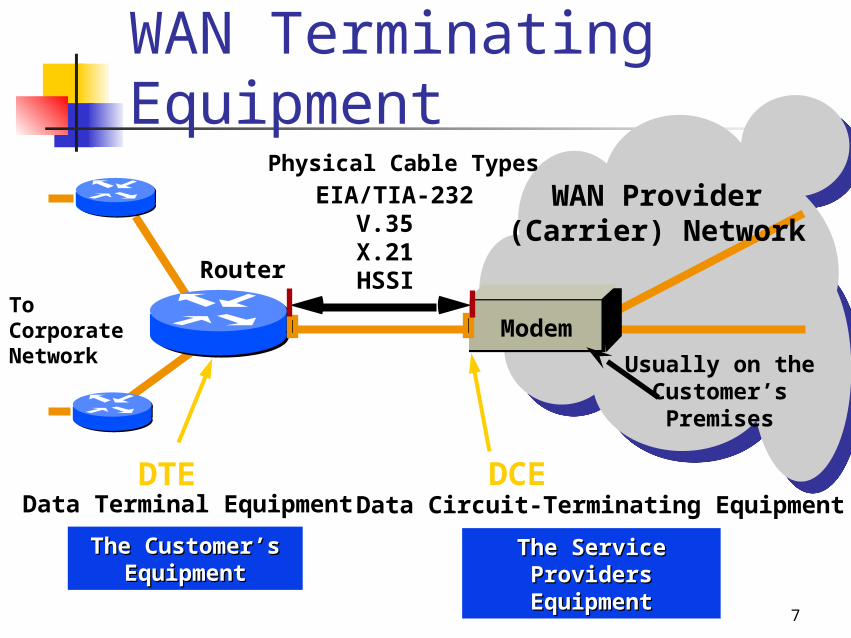
WAN Terminating Equipment
Modem
Data Terminal EquipmentDTE
Data Circuit-Terminating Equipment
The Service Providers The Service Providers EquipmentEquipment
DCE
EIA/TIA-232V.35X.21HSSI
To Corporate Network
The Customer’s The Customer’s EquipmentEquipment
WAN Provider(Carrier) Network
Physical Cable Types
Usually on the Customer’sPremises
Router
8
Wan Connection Types
Leased line Circuit switching Packet switching
9
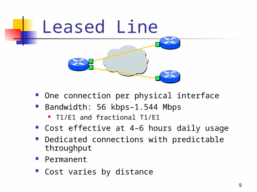
Leased Line
One connection per physical interface Bandwidth: 56 kbps–1.544 Mbps
T1/E1 and fractional T1/E1 Cost effective at 4–6 hours daily usage Dedicated connections with predictable
throughput Permanent Cost varies by distance
10
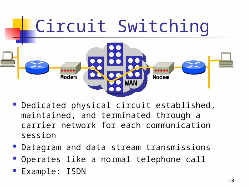
Dedicated physical circuit established, maintained, and terminated through a carrier network for each communication session
Datagram and data stream transmissions Operates like a normal telephone call Example: ISDN
WANModem Modem
Circuit Switching
11
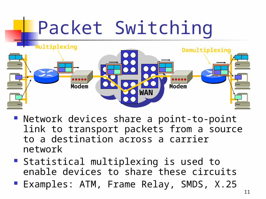
Network devices share a point-to-point link to transport packets from a source to a destination across a carrier network
Statistical multiplexing is used to enable devices to share these circuits
Examples: ATM, Frame Relay, SMDS, X.25
WANModem Modem
MultiplexingDemultiplexing
Packet Switching
12
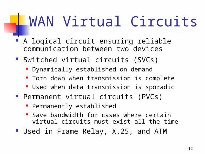
A logical circuit ensuring reliable communication between two devices
Switched virtual circuits (SVCs) Dynamically established on demand Torn down when transmission is complete Used when data transmission is sporadic
Permanent virtual circuits (PVCs) Permanently established Save bandwidth for cases where certain
virtual circuits must exist all the time Used in Frame Relay, X.25, and ATM
WAN Virtual Circuits
13
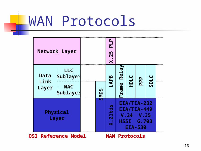
OSI Reference Model
PhysicalLayer
DataLink
Layer
Network Layer
LLCSublayer
MACSublayer
SM
DS
X.2
1bis
EIA/TIA-232EIA/TIA-449V.24 V.35
HSSI G.703EIA-530
HD
LC
PP
PWAN Protocols
LA
PB
X.2
5 P
LP
Fra
me
Rel
ay
SD
LC
WAN Protocols
14
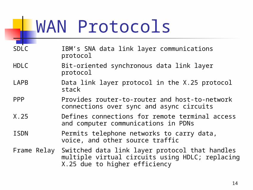
SDLC IBM’s SNA data link layer communications protocol
HDLC Bit-oriented synchronous data link layer protocol
LAPB Data link layer protocol in the X.25 protocol stack
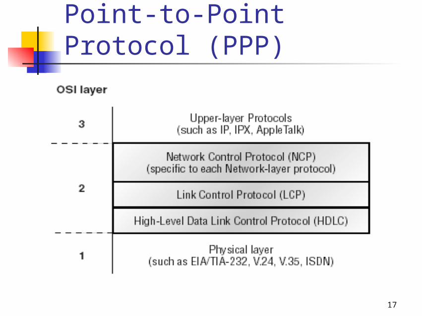
PPP Provides router-to-router and host-to-network connections over sync and async circuits
X.25 Defines connections for remote terminal access and computer communications in PDNs
ISDN Permits telephone networks to carry data, voice, and other source traffic
Frame Relay Switched data link layer protocol that handles multiple virtual circuits using HDLC; replacing X.25 due to higher efficiency
WAN Protocols
15
Point-to-Point Protocol (PPP)
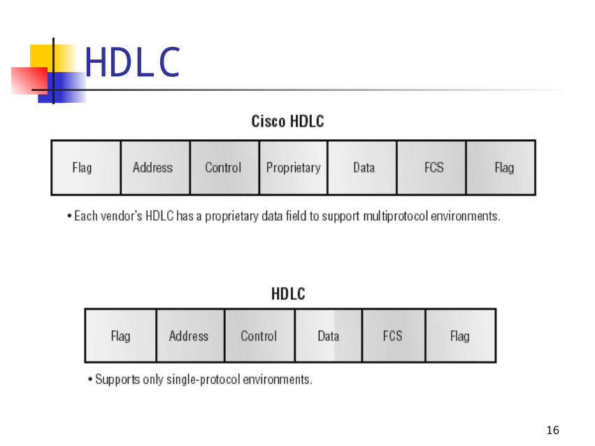
16
HDLC
17
Point-to-Point Protocol (PPP)
18
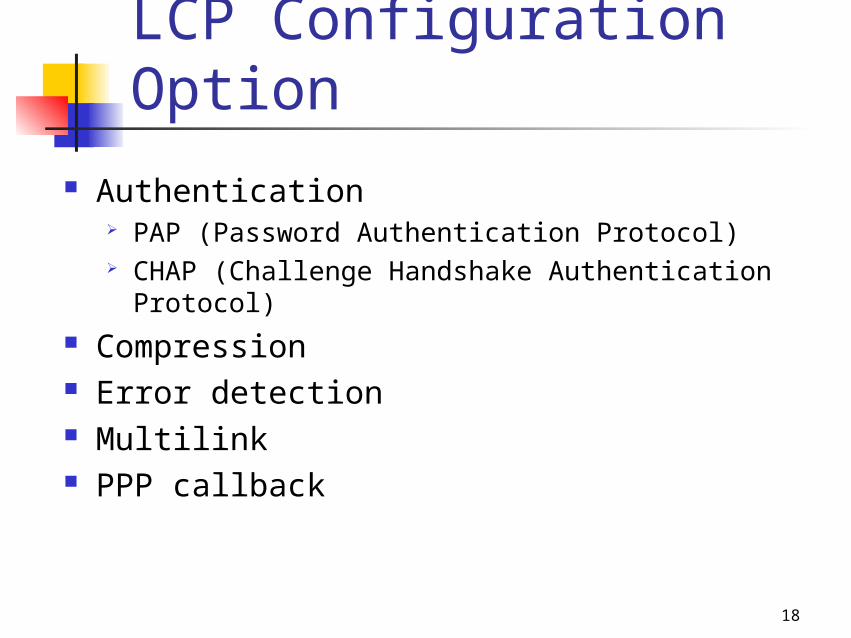
LCP Configuration Option
Authentication PAP (Password Authentication Protocol) CHAP (Challenge Handshake Authentication
Protocol) Compression Error detection Multilink PPP callback
19
PPP Session Establishment
Link-establishment phase Authentication phase Network layer protocol phase
20
Integrated Services Digital Network (ISDN)
21
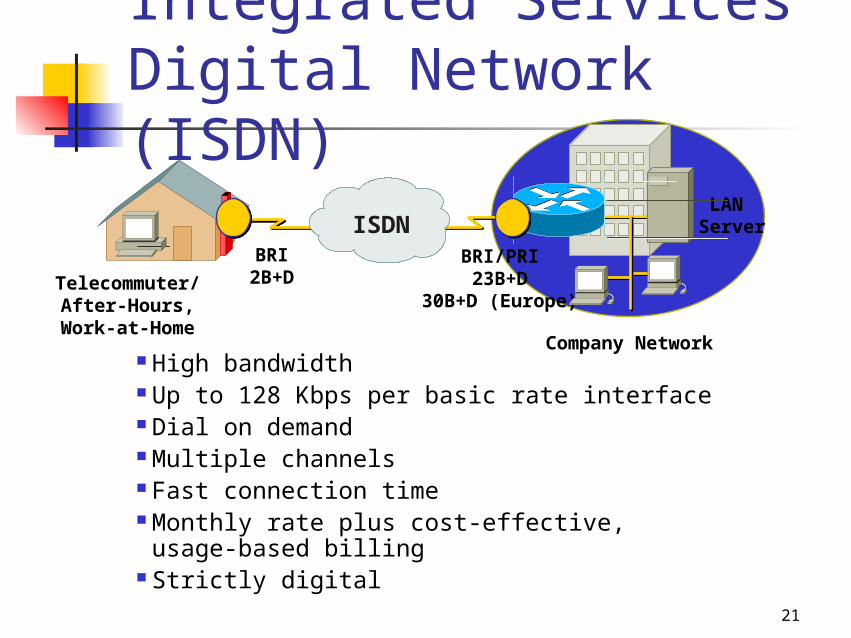
Integrated Services Digital Network (ISDN)
High bandwidth Up to 128 Kbps per basic rate interface Dial on demand Multiple channels Fast connection time Monthly rate plus cost-effective,
usage-based billing Strictly digital
LAN Server
Company Network
Telecommuter/After-Hours, Work-at-Home
BRI2B+D
BRI/PRI23B+D
30B+D (Europe)
ISDN
22
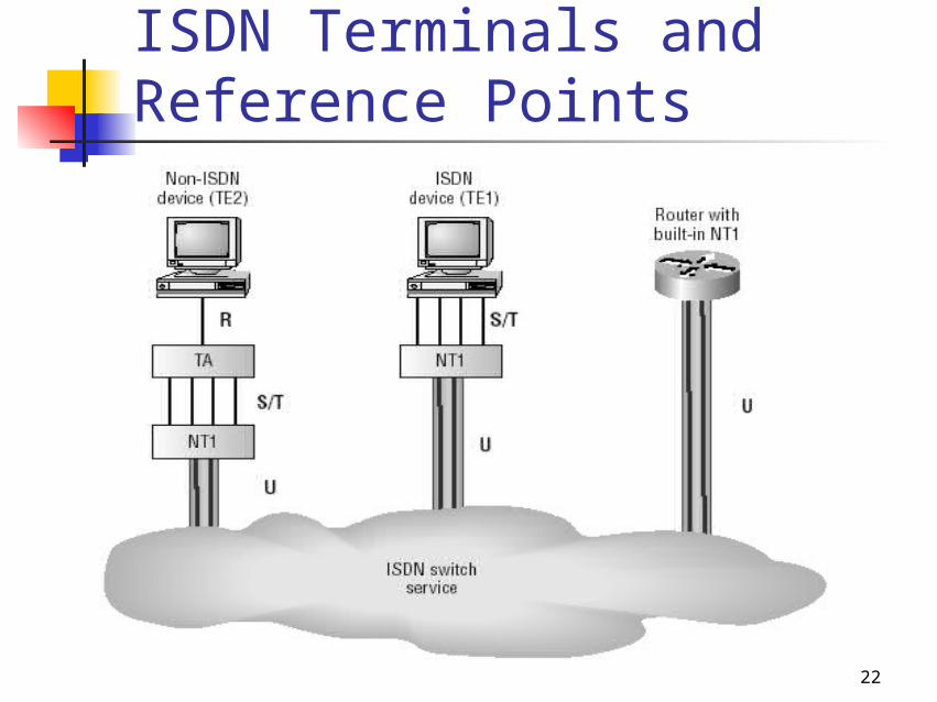
ISDN Terminals and Reference Points
23
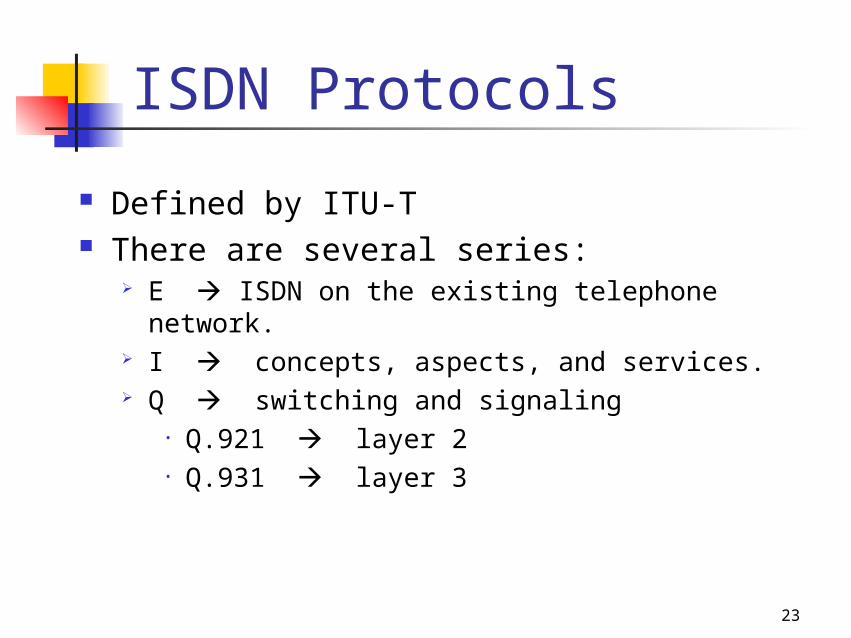
ISDN Protocols
Defined by ITU-T There are several series:
E ISDN on the existing telephone network. I concepts, aspects, and services. Q switching and signaling
• Q.921 layer 2• Q.931 layer 3
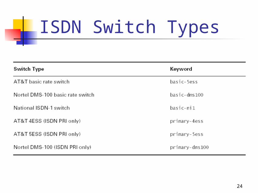
24
ISDN Switch Types
25
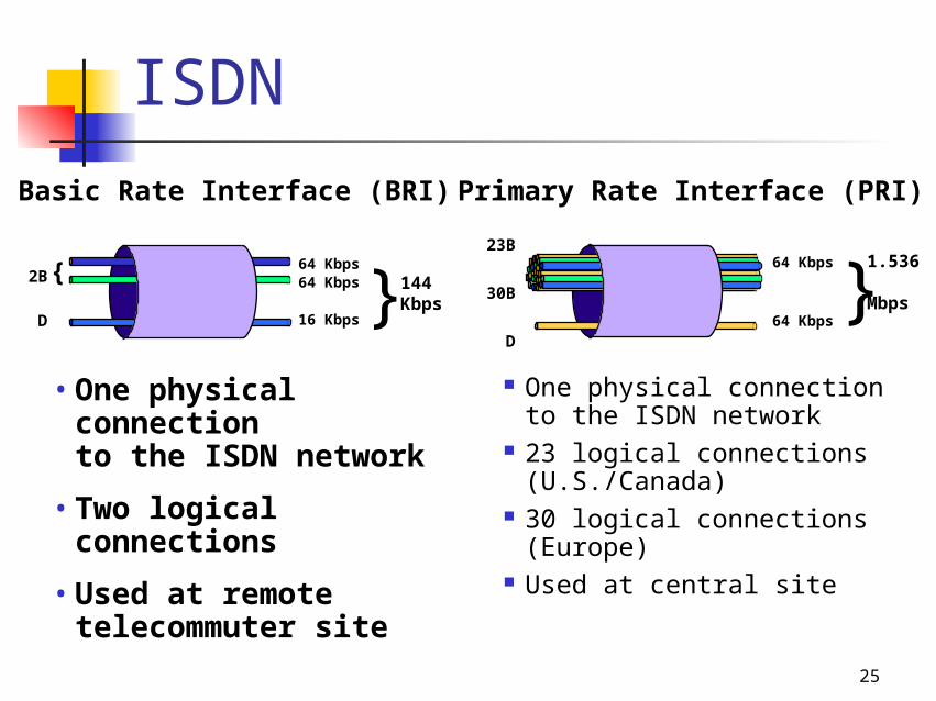
ISDN
One physical connection to the ISDN network
23 logical connections (U.S./Canada)
30 logical connections (Europe)
Used at central site
Primary Rate Interface (PRI)
1.536 Mbps
23B
30B
D
64 Kbps
64 Kbps}
• One physical connection to the ISDN network
• Two logical connections
• Used at remote telecommuter site
64 Kbps64 Kbps
16 Kbps
144 Kbps
2B
D }{
Basic Rate Interface (BRI)
26
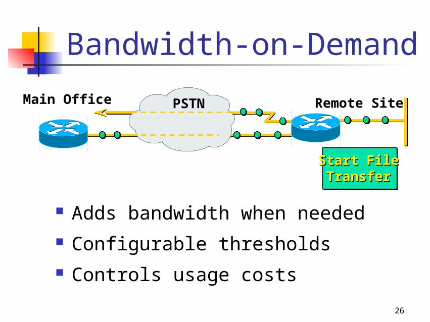
Bandwidth-on-Demand
Adds bandwidth when needed Configurable thresholds Controls usage costs
Start FileStart FileTransferTransfer
Remote SiteMain Office PSTN
27
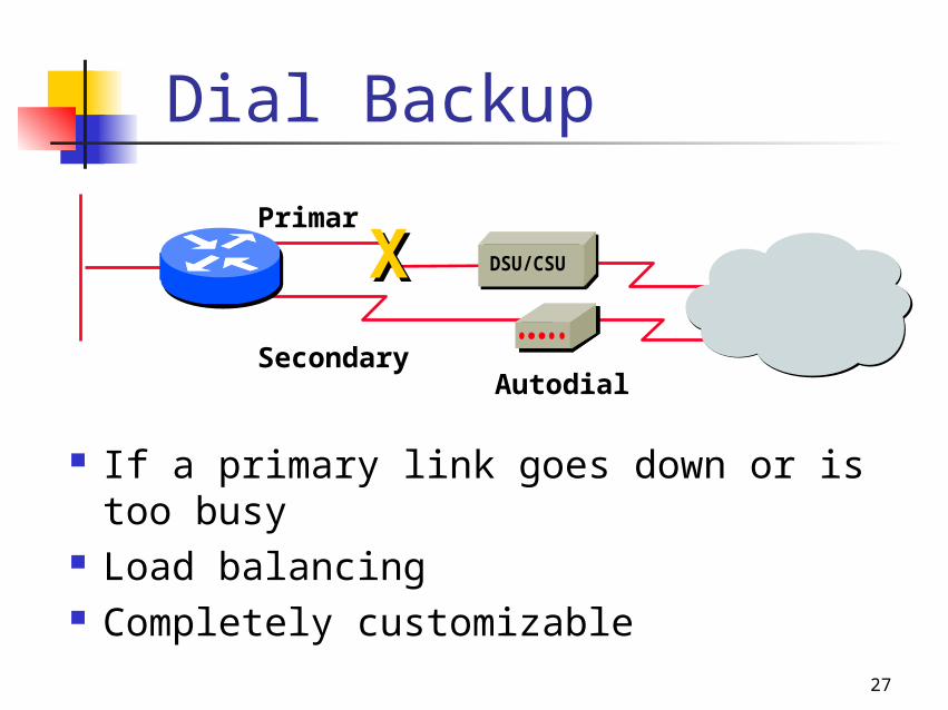
Dial Backup
If a primary link goes down or is too busy
Load balancing Completely customizable
Secondary
Primary
Autodial
DSU/CSUXX
28
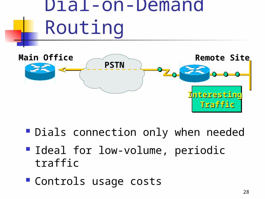
Dial-on-Demand Routing
Dials connection only when needed Ideal for low-volume, periodic traffic Controls usage costs
Interesting Interesting TrafficTraffic
Remote SiteMain OfficePSTN
29
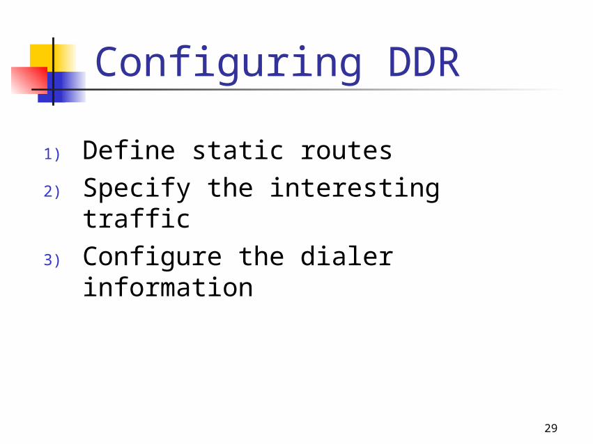
Configuring DDR
1) Define static routes2) Specify the interesting traffic3) Configure the dialer information
30
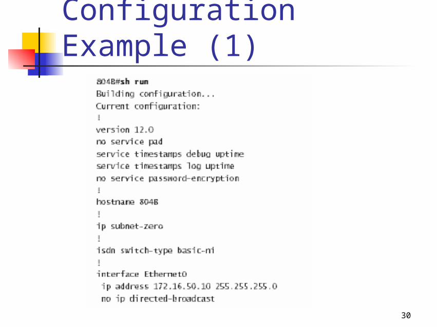
Configuration Example (1)
31
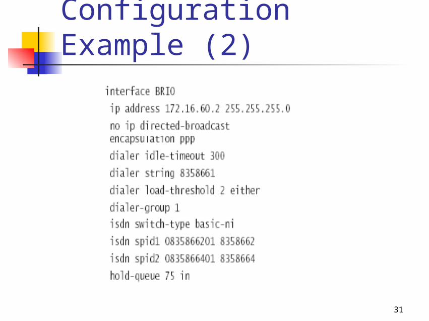
Configuration Example (2)
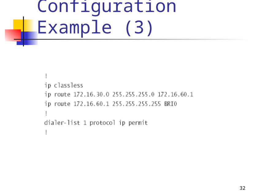
32
Configuration Example (3)
33
Frame Relay
34
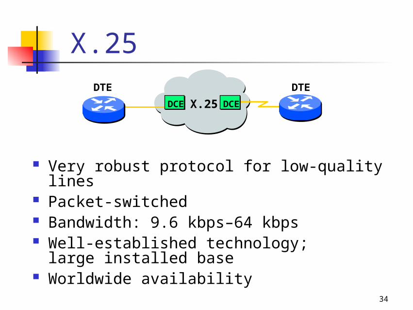
X.25
Very robust protocol for low-quality lines Packet-switched Bandwidth: 9.6 kbps–64 kbps Well-established technology;
large installed base Worldwide availability
X.25DCE
DTE DTE
DCE
35
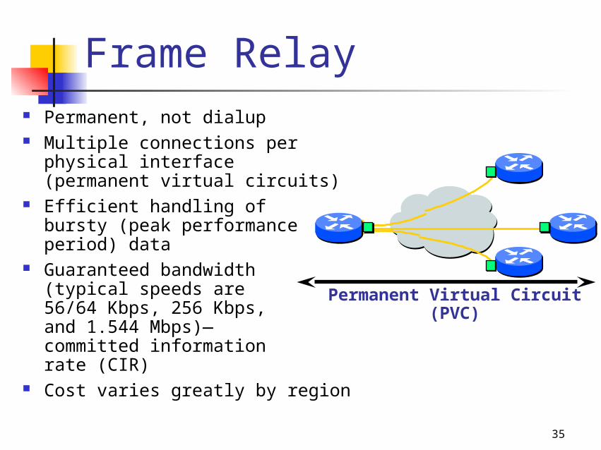
Frame Relay Permanent, not dialup Multiple connections per
physical interface (permanent virtual circuits)
Efficient handling of bursty (peak performance period) data
Guaranteed bandwidth (typical speeds are 56/64 Kbps, 256 Kbps, and 1.544 Mbps)—committed information rate (CIR)
Cost varies greatly by region
Permanent Virtual Circuit (PVC)
36
Committed Information Rate (CIR)
Access rate the maximum speed at which the Frame Relay interface can transmit.
CIR the maximum bandwidth of data guaranteed to be delivered.
37
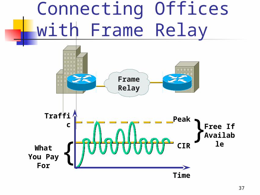
Free If Available
Traffic
Time
Peak
CIRWhat You Pay
For{
{Frame Relay
Connecting Offices with Frame Relay
38
Data Link Connection Identifier (DLCI)
Used to identify virtual circuits. Locally significant.
39
Local Management Interface (LMI)
Signaling standard between router and the first Frame Relay switch.
It communicates information about: Keepalives Multicasting Global addressing Status of virtual circuits
Virtual circuit status: Active state Inactive state Deleted state
40
Frame Relay Congestion Control
Discard Eligibility (DE) Forward Explicit Congestion
Notification (FECN) Backward Explicit Congestion
Notification (BECN)
41
Operate beyond the local LAN’s control Customers pay telephone service providers
for WAN connections such as ISDN, xDSL, Frame Relay, leased line, X.25, etc.
Switching methods include point-to-point, circuit switching, packet switching, dialup, and WAN virtual circuits
Key devices include WAN switches, access servers, modems, and CSU/DSUs
Bandwidth optimization features are essential for controlling WAN costs
WAN Summary