1 Incline Plane Estimated time required: 15 min GUI familiarity level required: Higher MSC.ADAMS...
12
1 Incline Plane Estimated time required: 15 min GUI familiarity level required: Higher MSC.ADAMS 2005 r2
-
Upload
marjory-hood -
Category
Documents
-
view
218 -
download
1
Transcript of 1 Incline Plane Estimated time required: 15 min GUI familiarity level required: Higher MSC.ADAMS...
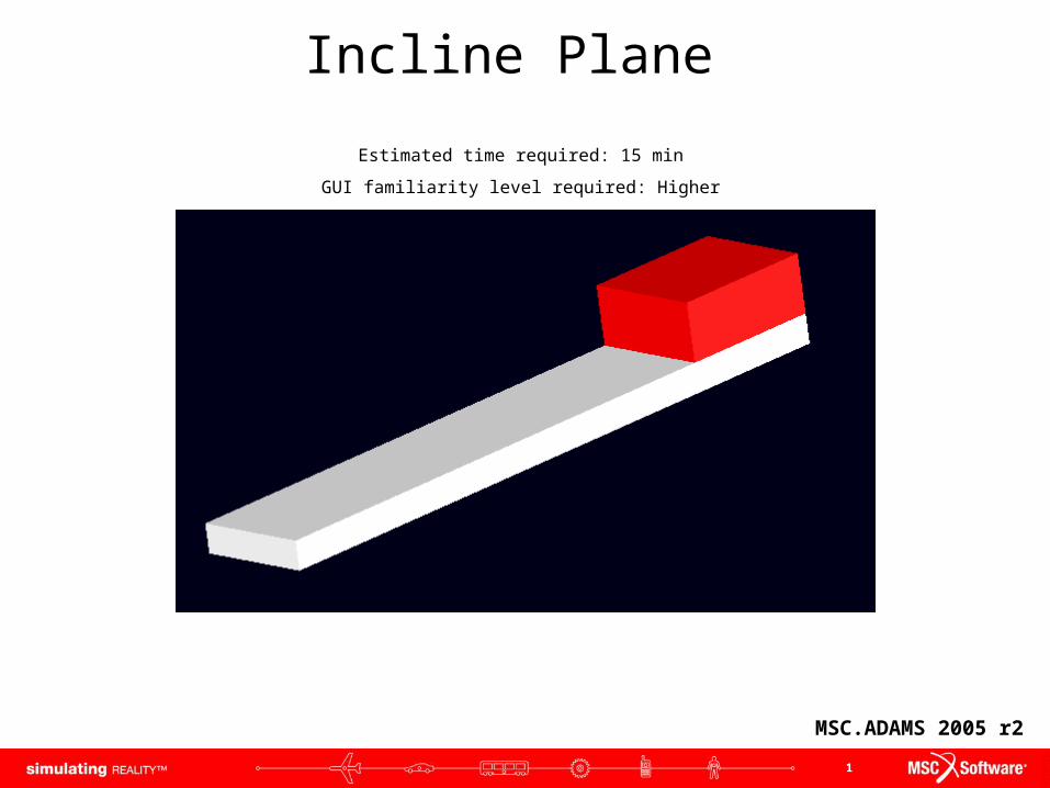
1
Incline Plane
Estimated time required: 15 min
GUI familiarity level required: Higher
MSC.ADAMS 2005 r2

2
Topics CoveredTopics Covered
If you have any difficulties, import the “incline_shortcut.cmd” file and proceed from pg 7
If you have any difficulties, import the “incline_complete_15deg.cmd” file and proceed from pg 8
If you have any difficulties, import the “incline_complete_20deg.cmd” file and proceed from pg 10
In this tutorial, you will learn how to:
1. Add friction to a translational joint
2. Change friction input forces
3
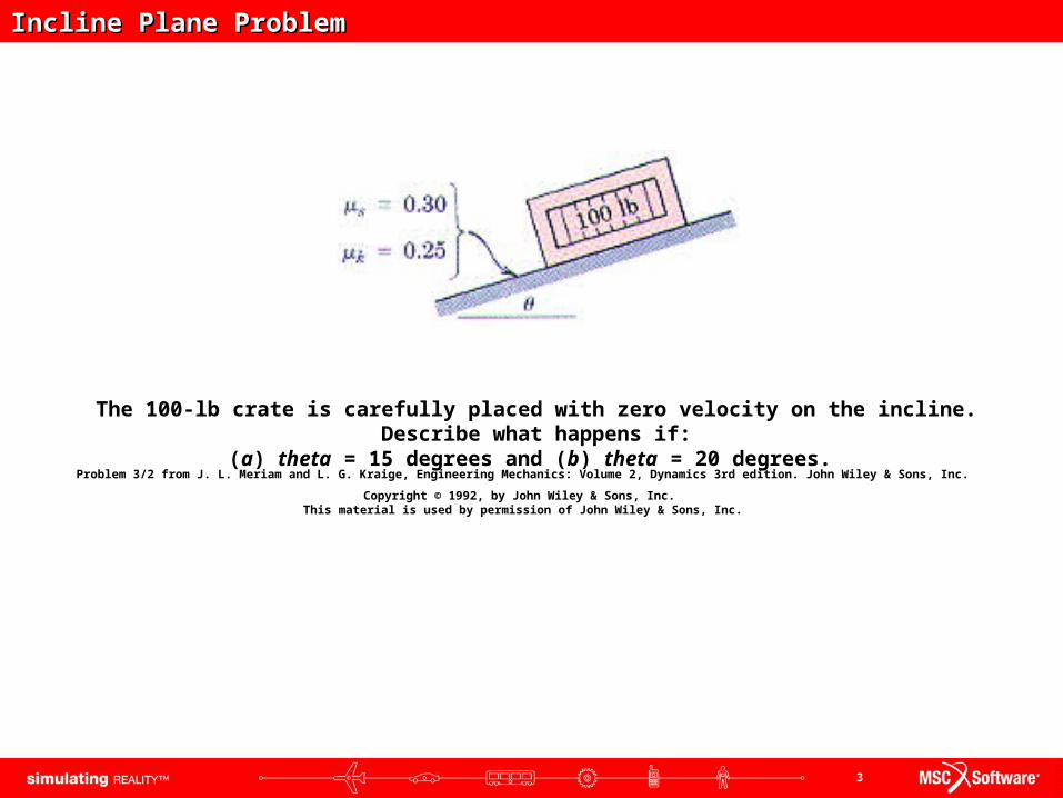
Incline Plane ProblemIncline Plane Problem
Problem 3/2 from J. L. Meriam and L. G. Kraige, Engineering Mechanics: Volume 2, Dynamics 3rd edition. John Wiley & Sons, Inc.
Copyright © 1992, by John Wiley & Sons, Inc. This material is used by permission of John Wiley & Sons, Inc.
The 100-lb crate is carefully placed with zero velocity on the incline. Describe what happens if:(a) theta = 15 degrees and (b) theta = 20 degrees.

4
If you are successful, you should end up with a ADAMS model that illustrates a box with friction traveling down
an incline.
What You Should AccomplishWhat You Should Accomplish

5
Creating the ModelCreating the Model
a. Start ADAMS.
b. Create a new model. (Model Name = incline, Units = ips, Gravity = - Y earth)
c. Resize the working grid, Size = X – 75i, Y – 50i, Spacing X – 1i, Y – 1i
d. Create ground plane. (box on ground, length = 46 in, height = 2 in, depth = 8 in)
e. Create crate part. (box, length = 10 in, height = 4 in, depth = 8 in, mass = 100 lb), rename .incline.BLOCK
6
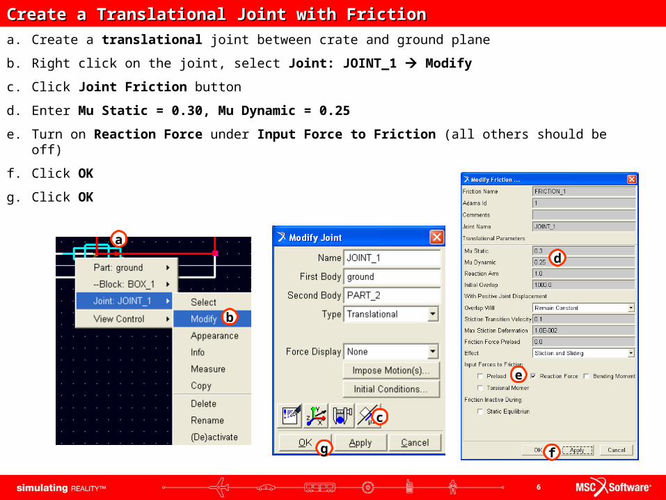
Create a Translational Joint with FrictionCreate a Translational Joint with Friction
a. Create a translational joint between crate and ground plane
b. Right click on the joint, select Joint: JOINT_1 Modify
c. Click Joint Friction button
d. Enter Mu Static = 0.30, Mu Dynamic = 0.25
e. Turn on Reaction Force under Input Force to Friction (all others should be off)
f. Click OK
g. Click OK
a
b
c
d
f
e
g

7
Test Model at 15Test Model at 15°°
a. Rotate model to angle theta = 15 degrees. (select both the plane and the crate, and use the rotate tool)
b. Run simulation and record results. (end time = 1, time steps = 50)

8
Test Model at 20°Test Model at 20°
a. Rotate to new angle theta = 20 degrees. (20 degrees from ground)
b. Measure the mag (magnitude) of the CM acceleration
c. Run another simulation.
d. Transfer the small graph to a full plot in the ADAMS plotting screen. (right mouse button inside small plotting window)
e. Use the Display Plot Statistics tool to follow the plot curve. Find the value for Y when X = 1.0

9
This is what your screen should look like whenyour model is complete
ModelModel
10
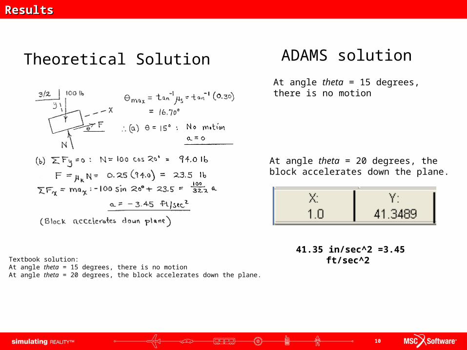
Theoretical Solution ADAMS solution
ResultsResults
Textbook solution:At angle theta = 15 degrees, there is no motionAt angle theta = 20 degrees, the block accelerates down the plane.
41.35 in/sec^2 =3.45 ft/sec^2
At angle theta = 15 degrees, there is no motion
At angle theta = 20 degrees, the block accelerates down the plane.
11
In this tutorial you learned how to:
Topics CoveredTopics Covered
1. Add friction to a translational joint
2. Change friction input forces
12
Best PracticesBest Practices
• Make sure correct units are set to ips.
• For ease of part creation, the working grid can be set to inches.
• Make sure gravity is on and in the -y direction and set to -386.089.
• Check weight of crate to make sure it is correct. It may need to be set manually.
• Check dimensions of parts. Make sure the measures are set correctly.
• Make sure the plot is displaying the correct set of results.
• Make sure there are enough output steps to observe the effect at each angle setting