1. ESW AND PLASMA ARC WELDING.pptx
36
1 WELDING TECHNOLOGY
-
Upload
aravindanil -
Category
Documents
-
view
27 -
download
6
description
hhhh
Transcript of 1. ESW AND PLASMA ARC WELDING.pptx

1
WELDING TECHNOLOGY

2
CLASSIFICATION OF WELDING PROCESSES
welding
Forge or Pressure Welding
( Under pressure without additional filler metal )
Fusion or non pressure welding
( With additional filler metal )
Forge or Pressure welding :- The work pieces are heated to plastic state .
They are joined together by applying pressure on them.
Sometimes no heating done.
No filler material is used.
Fusion or non- pressure welding :- Edges of work pieces to be joined & filler material are heated to a temp. above the melting point of the metal.
On solidification, weld is formed.

3
Fusion or non pressure welding
Welding heat created by
Gas Electric Arc Chemical reaction
Oxy-acetylene welding Thermit welding
Carbon arc Metal arc Atomic hydrogen Submerged arc Plasma arc Electro slag TIG MIG

4
Forge or pressure welding
Welding heat created by
Furnace Electric current Friction
Forge or furnace welding Resistance welding Friction welding
spot seam projection flash butt
5
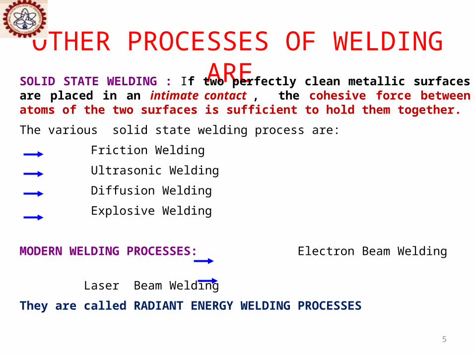
OTHER PROCESSES OF WELDING ARE SOLID STATE WELDING : If two perfectly clean metallic surfaces are placed in an intimate contact , the cohesive force between atoms of the two surfaces is sufficient to hold them together.
The various solid state welding process are:
Friction Welding
Ultrasonic Welding
Diffusion Welding
Explosive Welding
MODERN WELDING PROCESSES: Electron Beam Welding
Laser Beam Welding
They are called RADIANT ENERGY WELDING PROCESSES

6
WELDING TECHNOLOGYELECTIVE-I
M706
MODULE 41/3
7
SPECIAL OR
UNIQUE WELDING PROCESSESELECTROSLAG WELDINGPLASMA ARC WELDINGULTRASONIC WELDING
ELECTRON BEAM WELDINGLASER BEAM WELDING
FRICTION WELDINGEXPLOSIVE WELDING
COLD WELDING PROCESSES

8
THIS LECTURE COVERSELECTROSLAG WELDING
DEFINITIONPROCESSEQUIPMENTS
VARIENTSPOWER SOURCE
FLUXESADVANTAGESDISADVANTAGESAPPLICATIONS
PLASMA ARC WELDINGDEFINITIONTYPES
NON TRANSFERRED ARCTRANSFERRED ARC
THE PROCESSKEY HOLE WELDINGCOMPARISON WITH TIGADVANTAGESDISADVANTAGESAPPLICATIONS
9
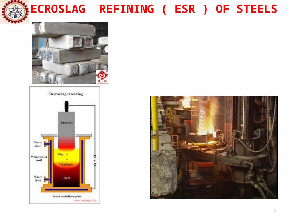
ELECROSLAG REFINING ( ESR ) OF STEELS

10
ELECTROSLAG WELDING

11
ELECTROSLAG WELDINGDEFINITION
A Vertical Welding process.Coalescence is produced by molten slag which melts the filler metal and the surface of the work pieces.
Continuous operation.
Consumable electrode.
Originated in Russia
Plates of 25 mm or more thickness can be joined.

12
An electric arc is initially struck between the electrode and the work pieces by a wire ( or steel wool) that is fed into the desired weld location.
The flux ( powdery, non conductive in solid state) is added.
The flux melts by the heat of the arc. This molten slag is conductive.
Additional flux is added until the molten slag, reaching the tip of the electrode, extinguishes the arc.
The slag pool remains molten due to its resistance to electric current passing between the electrode and work pieces.
Temp of molten slag pool- 1650◦C at surface and 1930◦C inside.
ELECTROSLAG WELDING--THE PROCESS
Electrode
WireWork piec Flux Workpiece
Base plate

13
The slag temperature melts the tip of the filler metal ( electrode) wire and the edges of the work pieces.
Molten metal from the tip of the wire electrodes drips through the molten slag.
Each such drop falling through the slag gets refined and gets collected on the molten metal pool above the work pieces.
This pool slowly solidifies , forms the weld bead.
This process of melting and solidification progresses upwards from bottom .
At any instant there is molten metal above the solidifying weld metal and molten conductive slag above the molten weld metal pool
Copper retaining shoes put into place before starting (can be water-cooled if desired) is used to hold the molten weld metal between the plates that are being welded.
Wire Electrodes
Guides
Copper slide
Solidified weld
ELECTROSLAG WELDING--THE PROCESS
Molten slag
Molten metal pool

14
ELECTROSLAG WELDINGTHE WELDING FLUX—
• Shields molten metal and reduces oxidation.
• Clears impurities from molten metal from electrode tip dropping through the slag pool.
• Added in small quantities periodically- no continuous addition needed.
• Has small rate of consumption ( Much less than submerged arc welding).
WATER COOLED COPPER SLIDES—
•Contain and confine molten slag and molten weld pool till they solidify.
•Accelerate solidification of weld pool by conduction.
15
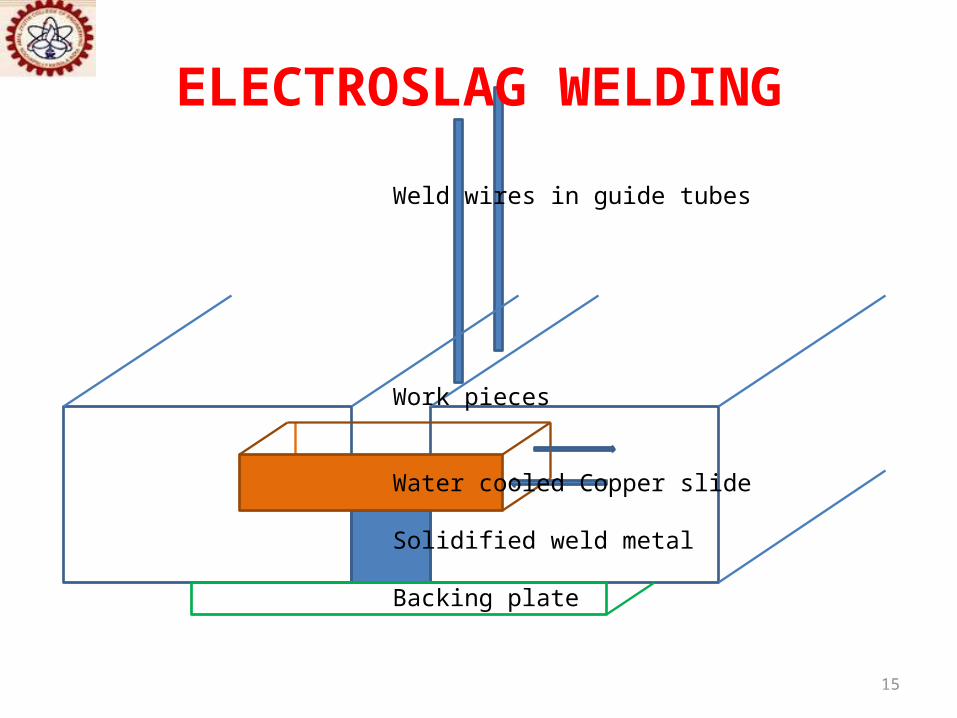
ELECTROSLAG WELDING
Weld wires in guide tubes
Work pieces
Water cooled Copper slide
Solidified weld metal
Backing plate

16
ELECTROSLAG WELDING

17
EQUIPMENTS
Source: American Welding Society.
ELECTROSLAG WELDING

18
ELECTROSLAG WELDINGCONVENTIONAL ELECTROSLAG WELDING
• Non consumable guide tubes ( < 12.5 mm dia ) used.
• Made of Cu-Be alloy.
• Current is conducted to the electrode wire by the guide tube.
• Welding head & Cu slides move up progressively as the weld is deposited, at a speed equal to the deposition rate.
• Electrode wires can be oscillated horizontally.
• To weld thick work pieces ( 18-460 mm).

19
ELECTROSLAG WELDINGCONSUMABLE GUIDE ELECTROSLAG WELDING
• A consumable guide tube used.
• Both guide and weld wire are of same material.
• Electrode wire melts inside molten slag, the guide tube melts off just above the surface of the slag.
• The welding machine does not move vertically during welding.
• The electrode wire and the guide tube move downwards as welding progresses.
• Two sets of non-sliding copper shoes are used. As weld progresses a set on the solidified joint area is removed and placed above the next set.
• Single or multiple weld wire feeds with / without oscillation.
Weld wire
Consumable guide tube
Molten slag molten metal drips through
Molten weld metal pool
Solidified weld
Work pieces

20
ELECTROSLAG WELDINGPOWER SOURCEDC ( Constant Voltage )AC ( Flat characteristics)
Typical ESW power source supplies 900 Amp , continuous wire feeding.
FLUXES - Should • be conductive in molten condition and carry the welding current from the electrode ( wire ) to the molten metal pool without arcing.• have medium viscosity.• have melting range less than that of the work pieces.• be metallurgically compatible with work pieces. • be easily removable from weld surface after welding is completed.
Contains SiO2, MnO, CaO, MgO, Al2O3. CaF2 increases electrical conductivity and lowers slag viscosity.

21
ADVANTAGES
High deposition rate - up to 45 lbs/h (20 kg/h),
Only single pass,
Low slag consumption (about 5% of the deposited metal weight),
No angular distortion as weld is symmetrical w.r.t. its axis,
No spattering as there is no arc,
Unlimited thickness of work piece ( 450 mm and more ).
ELECTROSLAG WELDING

22
DISADVANTAGES
Coarse grain structure of the weld due to high heat input,
Low toughness of the weld,
Only vertical position is possible.
ELECTROSLAG WELDING
TYPICAL THERMAL CYCLE OF AN ELECTROSLAG WELD RELATIVE TO THAT OF AN ARC WELDED WELD
FUSION ZONE AND HEAT-AFFECTED ZONE

23
ELECTROSLAG WELDING
APPLICATIONS
Electroslag Welding is used mainly for steels.
Heavy plates, forgings and castings can be welded.

24
PLASMA ARC WELDING
was introduced to the welding industry in 1964 as a method of bringing better control to
the arc welding process in lower current ranges.

25
PLASMA ARC WELDINGA gas-shielded arc welding process .
Metals are joined using the heat from an arc created between a tungsten electrode in a constricted nozzle and a workpiece.
The arc is constricted by a copper alloy nozzle orifice to form a highly collimated arc column .
( The plasma gas constricts the arc and leads to a more concentrated heat input than in TIG welding )
The plasma is formed through the ionization of a portion of the plasma (orifice) gas.
The process can be operated with or without a filler wire addition.

26
PLASMA ARC WELDING
DEFINITIONPlasma arc welding is an arc welding process that produces coalescene of metals by
heating them with a constricted arc between an electrode and the work
piece(transferred arc) or between the electrode and the constricting nozzle(non
transferred arc) .
Uses two inert gases- one for plasma , the other for shielding.

27
PLASMA ARC WELDINGCOMPARISON WITH TIG
TIG (GTAW) PAW
Major advantage of PAW over TIG-by positioning the electrode within the body of the torch, a constricted arc is formed.
Non constricted arc

28
PLASMA ARC ( CONSTRICTED) TIG ARC ( NON CONSTRICTED)
PLASMA ARC WELDING

29
Two types of plasma-arc welding processes:
(a) Transferred (b) Non-transferred
PLASMA ARC WELDING
Non- Trasferred PAW—Arc between electrode (-) and the constricted nozzle(+) struck by high frequency unit in circuit. Arc plasma comes out of the nozzle as a flame. Work piece is not a part of electrical circuit. Flame can be moved anywhere. Posses comparatively low energy density. Used for welding and in metal spraying.
Trasferred PAW—Arc between electrode (-) and the work piece(+) i.e, arc is transferred from electrode to work piece. Posses high energy density and plasma jet velocity. A pilot arc struck between electrode and the nozzle. As the pilot arc touches the workpiece, ignites the transferred arc. The pilot arc circuit gets disconnected. The pilot arc gets extinguished when the transferred arc strikes.

PLASMA ARC WELDING
THE PROCESS
• Clean the areas to be welded.
• Filler metal added.
NON KEYHOLE WELDING (melt-in-mode) - Normal welding of workpieces with thickness <24 mm.
Forms a bowl-shaped melted portion of the material of the workpiece under the arc ( as in gas-tungsten arc welding –GTAW / TIG - process ).
31
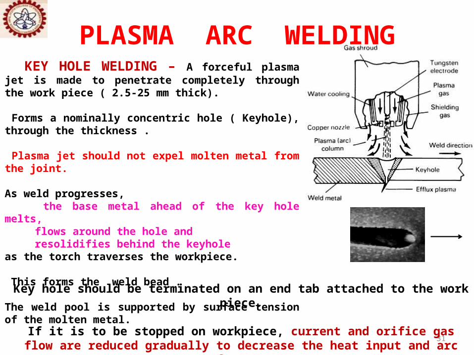
KEY HOLE WELDING – A forceful plasma jet is made to penetrate completely through the work piece ( 2.5-25 mm thick).
Forms a nominally concentric hole ( Keyhole), through the thickness .
Plasma jet should not expel molten metal from the joint.
As weld progresses, the base metal ahead of the key hole melts,
flows around the hole and resolidifies behind the keyhole as the torch traverses the workpiece.
This forms the weld bead .
The weld pool is supported by surface tension of the molten metal.
PLASMA ARC WELDING
Key hole should be terminated on an end tab attached to the work piece.
If it is to be stopped on workpiece, current and orifice gas flow are reduced gradually to decrease the heat input and arc force.
This allows molten metal to run into the key hole and solidify there.

32
PLASMA ARC WELDING
33
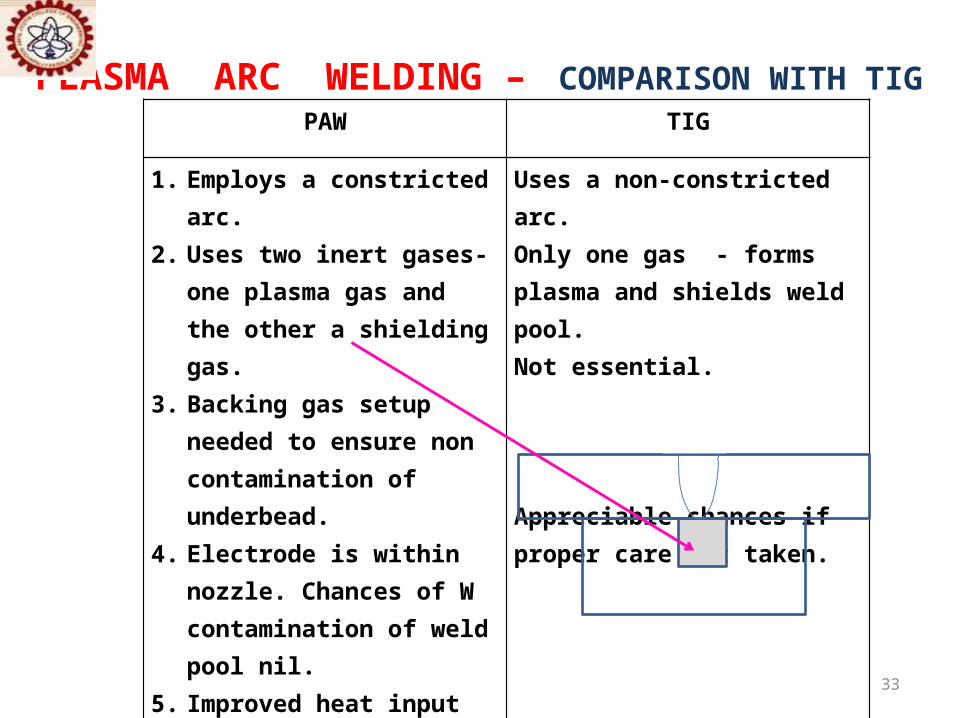
PLASMA ARC WELDING – COMPARISON WITH TIGPAW TIG
1. Employs a constricted arc.2. Uses two inert gases- one
plasma gas and the other a shielding gas.
3. Backing gas setup needed to ensure non contamination of underbead.
4. Electrode is within nozzle. Chances of W contamination of weld pool nil.
5. Improved heat input and distribution.
6. Better penetration.7. Filler metal requirements are
less as compared to TIG.8. Faster deposition.
Uses a non-constricted arc.Only one gas - forms plasma and shields weld pool.Not essential.
Appreciable chances if proper care not taken.
Comparatively slower.

34
PLASMA ARC WELDING
ADVANTAGES DISADVANTAGES Stable arc. Infra red and ultraviolate radiations- protection devices needed.
Uniform penetration. Unpleasant, disturbing noise, More electrical hazards .
Simple fixtures. Process limited to <25 mm thickness.
Fully penetrated keyhole welds Complicated equipments.on pieces upto 12 mm .
Excellent weld quality. High Inert gas consumption.
35
PLASMA ARC WELDING
APPLICATIONS
•Carbon and low alloy steels, Stainless steels, Cu,Ti,Ni,Co, Al alloys.
•Cryogenic, aerospace and high temp corrosion resistant materials.
•Nuclear applications.
•Melting high melting point alloys.
•Metal Spraying , Cutting of difficult to cut alloys.

36
THANK YOU