1 DC ELECTRICAL CIRCUITS ELECTRONIC TRAINER AND BREADBOARDING.
29
1 DC ELECTRICAL CIRCUITS ELECTRONIC TRAINER AND BREADBOARDING
-
Upload
lily-baldwin -
Category
Documents
-
view
229 -
download
9
Transcript of 1 DC ELECTRICAL CIRCUITS ELECTRONIC TRAINER AND BREADBOARDING.

1
DC ELECTRICAL CIRCUITS
ELECTRONIC TRAINER AND BREADBOARDING
2
DC ELECTRICAL CIRCUITS
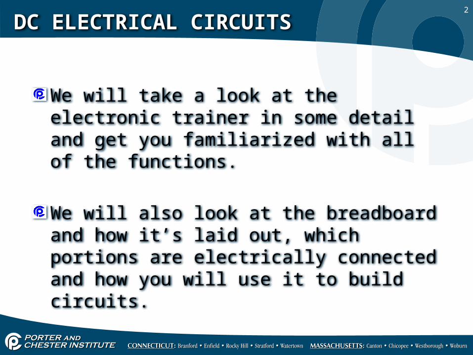
We will take a look at the electronic trainer in some detail and get you familiarized with all of the functions.
We will also look at the breadboard and how it’s laid out, which portions are electrically connected and how you will use it to build circuits.
3
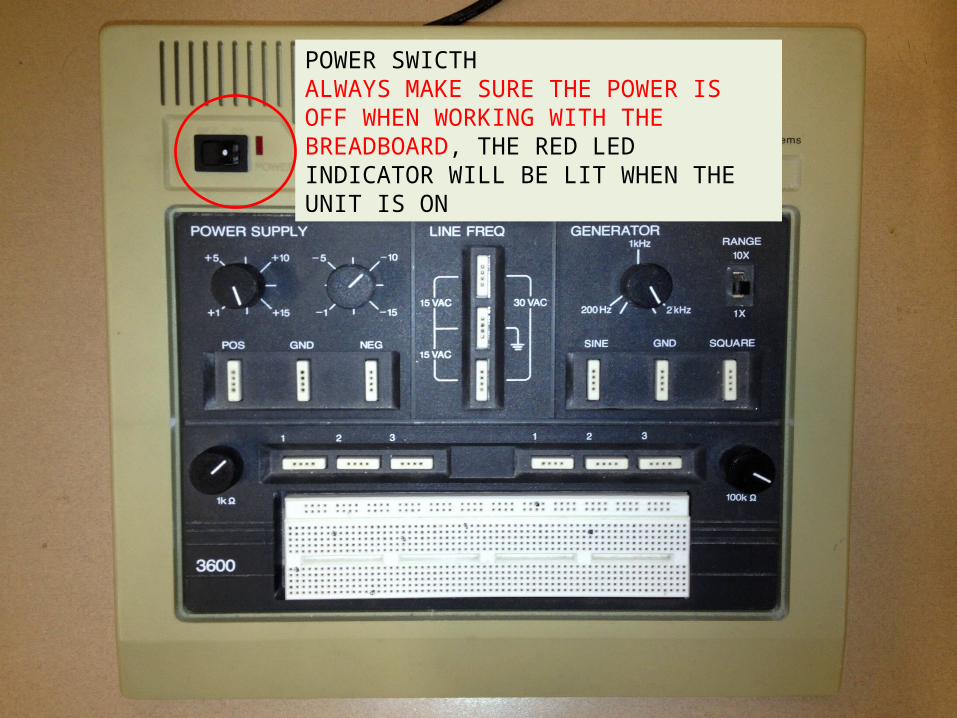
DC ELECTRICAL CIRCUITSPOWER SWICTH ALWAYS MAKE SURE THE POWER IS OFF WHEN WORKING WITH THE BREADBOARD, THE RED LED INDICATOR WILL BE LIT WHEN THE UNIT IS ON
4
DC ELECTRICAL CIRCUITS
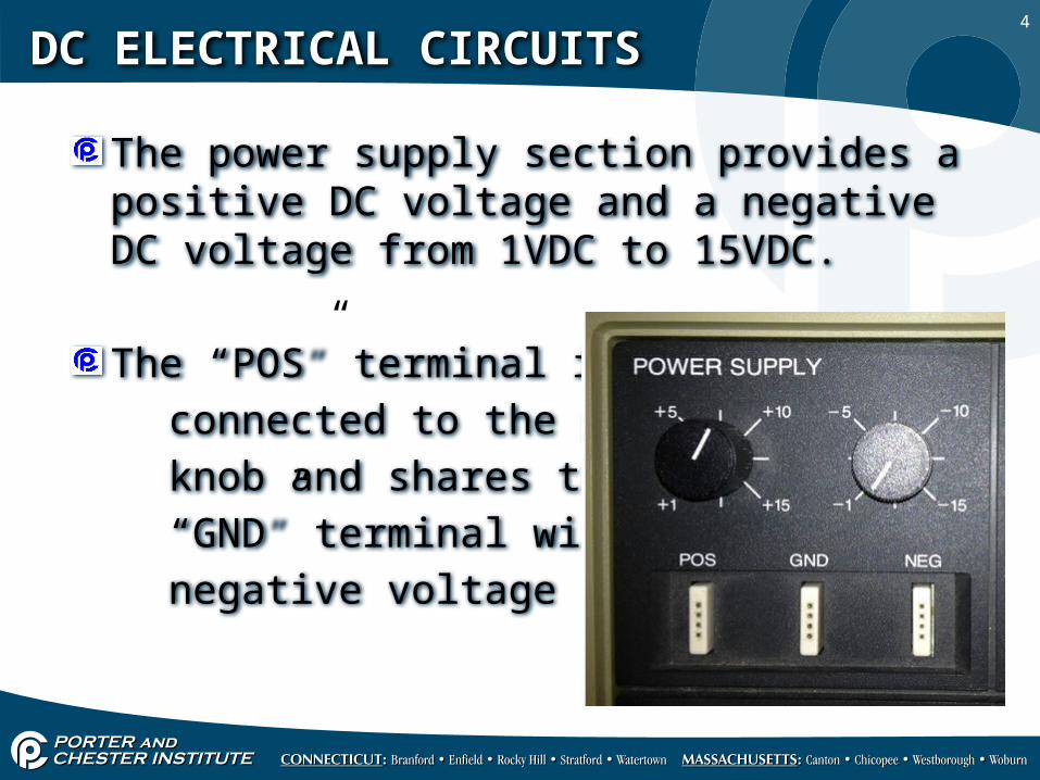
The power supply section provides a positive DC voltage and a negative DC voltage from 1VDC to 15VDC.
The “POS” terminal is connected to the positive knob and shares the ground “GND” terminal with the negative voltage supply.
5
DC ELECTRICAL CIRCUITS
Like wise the “NEG” terminal is connected to the knob for the negative DC voltages, and shares the ground terminal, the negative power supply is simply a polarity change.
To increase the voltages the knob must be turned counter clock wise, the abbreviation (ccw) will be used frequently throughout your heath kit lab exercises.
6
DC ELECTRICAL CIRCUITS
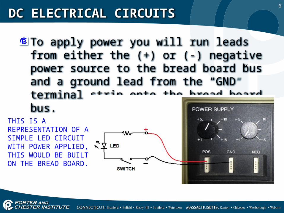
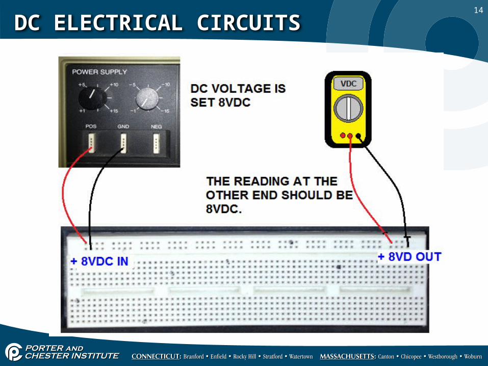
To apply power you will run leads from either the (+) or (-) negative power source to the bread board bus and a ground lead from the “GND” terminal strip onto the bread board bus.
THIS IS A REPRESENTATION OF A SIMPLE LED CIRCUIT WITH POWER APPLIED, THIS WOULD BE BUILT ON THE BREAD BOARD.
7
DC ELECTRICAL CIRCUITS
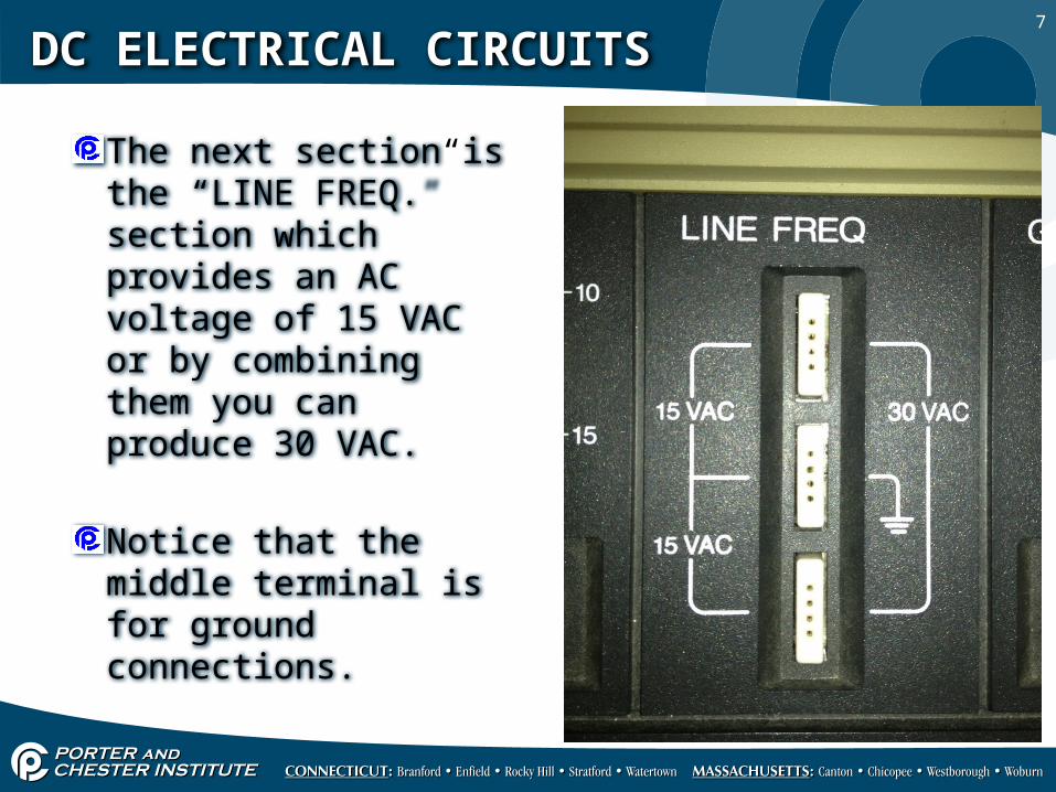
The next section is the “LINE FREQ.” section which provides an AC voltage of 15 VAC or by combining them you can produce 30 VAC.
Notice that the middle terminal is for ground connections.

8
DC ELECTRICAL CIRCUITS
The generator section provides a line frequency from 200Hz to 2000Hz (2KHz), the range of the frequency can be increased by 10 times higher using the range switch, (2KHz to 20KHz).

9
DC ELECTRICAL CIRCUITS
The 1K ohm knob is a potentiometer (variable resistor) that technically provides resistance from 1 to 1000Ω, you will find it will vary slightly, terminals 1 & 2 are variable and terminals 1 & 3 are fixed at 1000Ω.
10
DC ELECTRICAL CIRCUITS
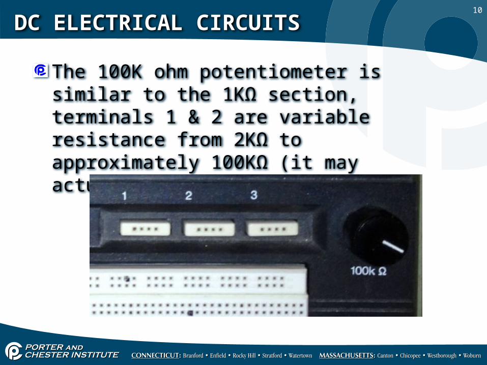
The 100K ohm potentiometer is similar to the 1KΩ section, terminals 1 & 2 are variable resistance from 2KΩ to approximately 100KΩ (it may actually be around 90KΩ).

11
DC ELECTRICAL CIRCUITS
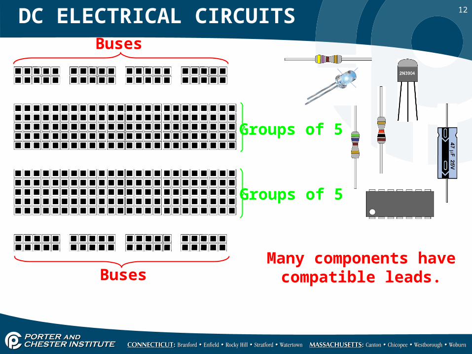
This is the bread board at the bottom of the electronics trainer that you will be building your circuits on.
12
Buses
Buses
Groups of 5
Groups of 5
Many components havecompatible leads.
DC ELECTRICAL CIRCUITS

13
DC ELECTRICAL CIRCUITS
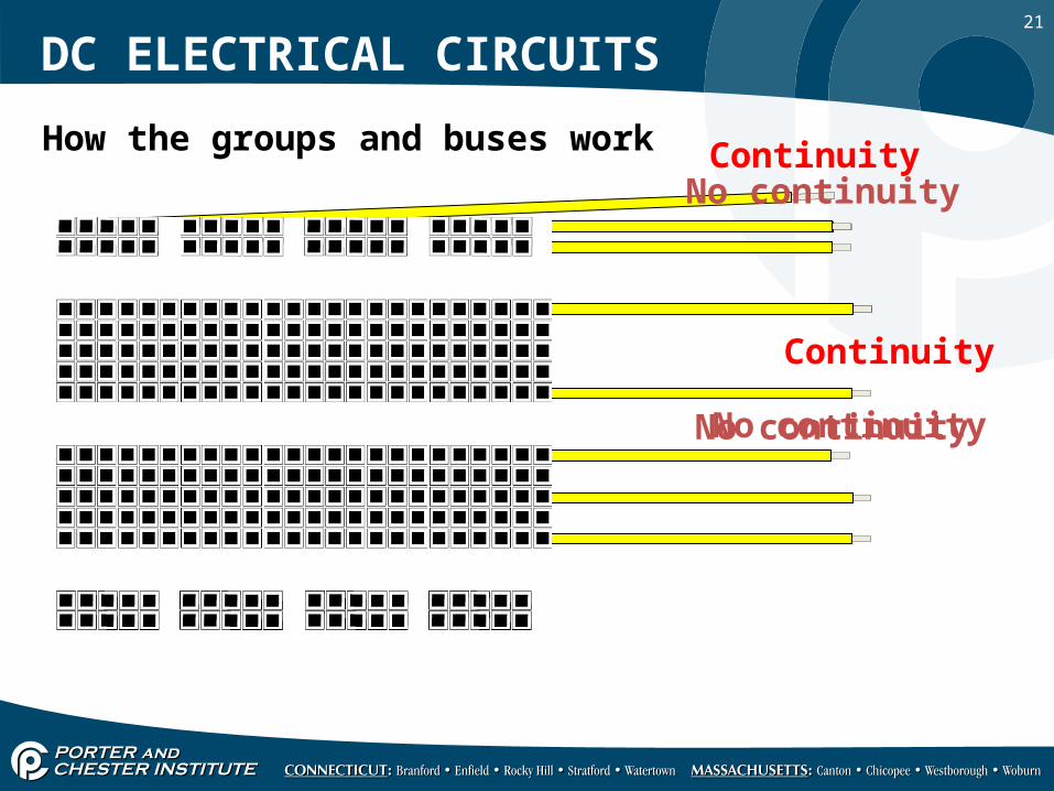
The buses are used to bring power onto the bread board.
The top rows in each segment are all electrically connected, you can verify this with your DMM.
The buses are not common with the rest of the bread board they’re electrically disconnected from the rest of the board.
14
DC ELECTRICAL CIRCUITS
15
DC ELECTRICAL CIRCUITS
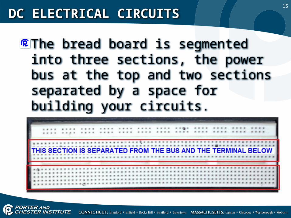
The bread board is segmented into three sections, the power bus at the top and two sections separated by a space for building your circuits.
16
DC ELECTRICAL CIRCUITS
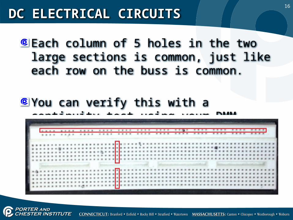
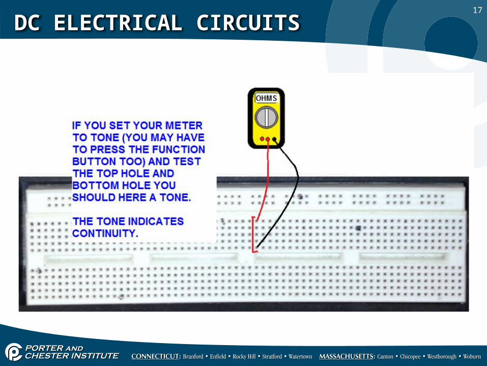
Each column of 5 holes in the two large sections is common, just like each row on the buss is common.
You can verify this with a continuity test using your DMM.
17
DC ELECTRICAL CIRCUITS
18
DC ELECTRICAL CIRCUITS
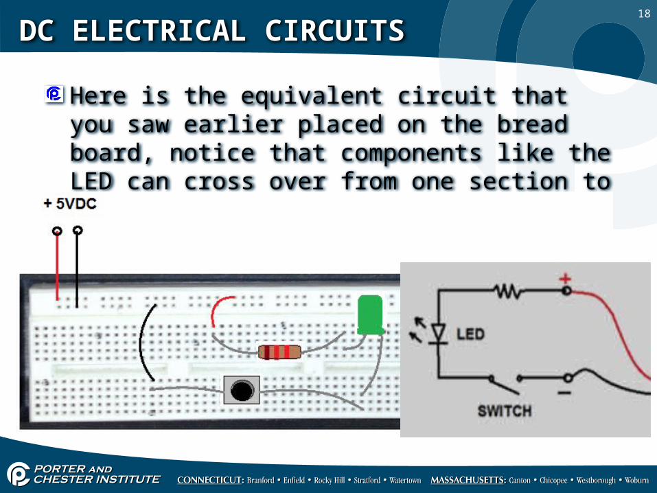
Here is the equivalent circuit that you saw earlier placed on the bread board, notice that components like the LED can cross over from one section to another.

19
DC ELECTRICAL CIRCUITS
You will be using 22 AWG solid wire as jumpers to connect component from terminal strip to other parts of the bread board.
20
DC ELECTRICAL CIRCUITS
The next slides will take you through a review process of the terminals and then we will look at building a circuit piece by piece.
Remember to shut off the power while you’re building circuits.
21
Continuity
No continuity
ContinuityNo continuity
No continuity
How the groups and buses work
DC ELECTRICAL CIRCUITS

22
1 kW
560 W
470 W
Series circuit
+
+
DC ELECTRICAL CIRCUITS
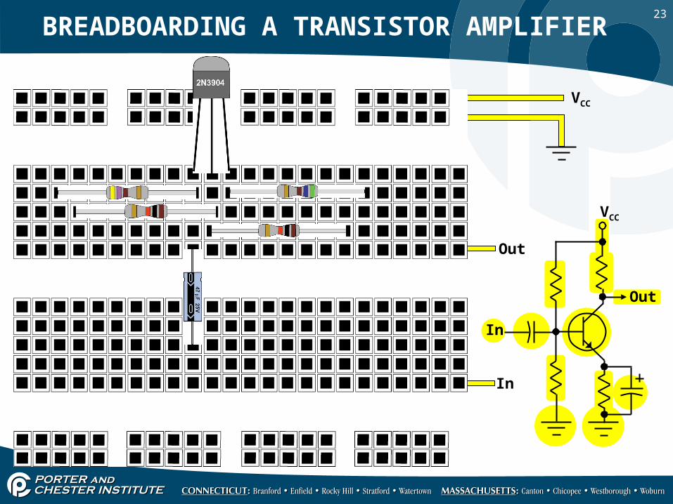
23
.47/
63VCC
VCC
In
Out
In
Out
BREADBOARDING A TRANSISTOR AMPLIFIER

24
.47/
63VCC
VCC
In
Out
In
Out
Previous slide Is this also correct?
DC ELECTRICAL CIRCUITS
25
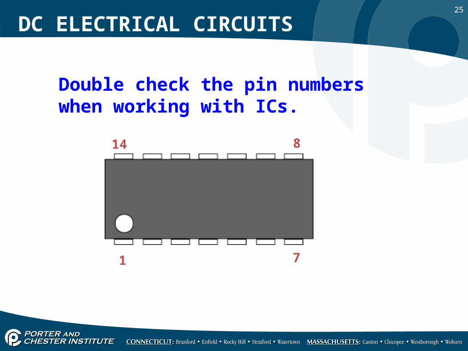
Double check the pin numbers when working with ICs.
1 7
814
DC ELECTRICAL CIRCUITS

26
VCC
A digital circuit
Pull-up
Current limit
VCC
Observepolarity!
A
A C
C
DC ELECTRICAL CIRCUITS

27
DC ELECTRICAL CIRCUITS
GENERAL GUIDELINES
Do not force wires larger than #20 gage. Add soldered extensions using #22 solid wire.
Use an IC removal tool or use a screwdriver to carefully pry up ICs for removal.
Use buses for power and ground distribution.
Add bypass capacitors to power buses.

28
DC ELECTRICAL CIRCUITS
Check and recheck before applying power.
Cut off ends and re-strip jumpers when they are worn.
Do not breadboard high power, high current or high voltage circuits.
29
DC ELECTRICAL CIRCUITS
RF circuits usually won’t work properly, if at all.
Keep high gain circuits inline and avoid long jumpers.
Adapters are available for SMT devices.