Combinational Circuit – Arithmetic Circuit Parallel Adder Example: 4-bit adder.
Upload
jayson-phelpsCategory
view
221download
3
1
Chapter 6
Functions of Combinational Logic

2
Figure 6--1 Logic symbol for a half-adder
Adder

3

4
Figure 6--2 Half-adder logic diagram.
5
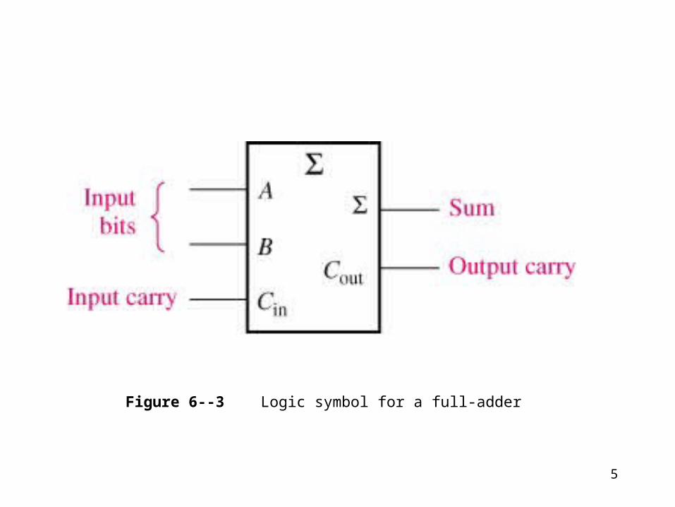
Figure 6--3 Logic symbol for a full-adder

6

7
Figure 6--4 Full-adder logic

8
Figure 6--5 Full-adder implemented with half-adders.

9
Figure 6--7 Block diagram of a basic 2-bit parallel adder using two full-adders.
10
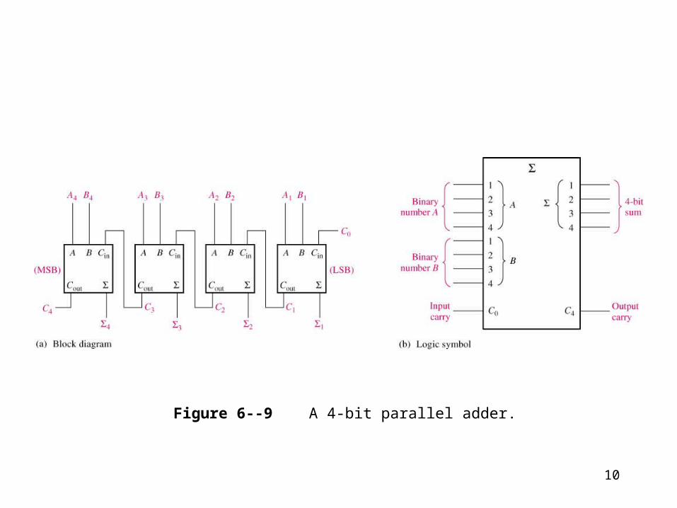
Figure 6--9 A 4-bit parallel adder.

11
Figure 6--10 Four-bit parallel adders.

12
Figure 6--12 Examples of adder expansion.

13
Figure 6--13 Two 74LS83A adders connected as an 8-bit parallel adder (pin numbers are in parentheses).
14
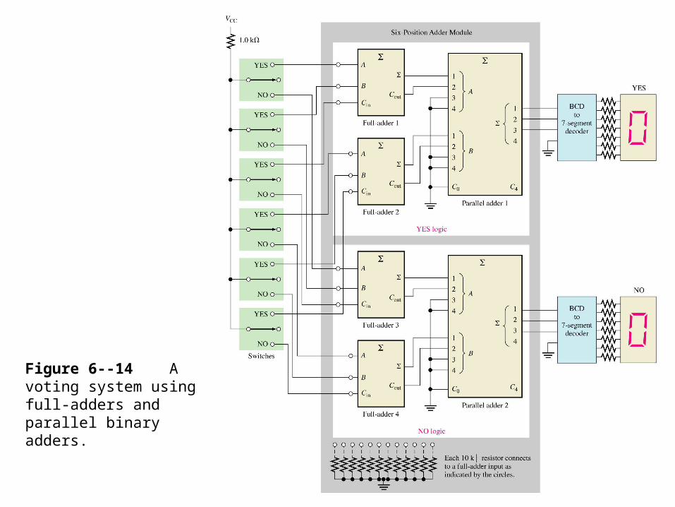
Figure 6--14 A voting system using full-adders and parallel binary adders.

15
Figure 6--15 Basic comparator operation. (Equality)
Comparators

16
Figure 6--16 Logic diagram for equality comparison of two 2-bit numbers

17
Figure 6--17 : Example 6-5

18
Figure 6--18 Logic symbol for a 4-bit comparator with inequality indication.
19
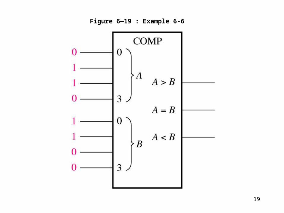
Figure 6—19 : Example 6-6

20
Figure 6--20 Pin diagram and logic symbol for the 74HC85 4-bit magnitude comparator (pin numbers are in parentheses).

21
Figure 6--21 An 8-bit magnitude comparator using two 74HC85s.

22
Figure 6--22 Decoding logic for the binary code 1001 with an active-HIGH output.
Decoders

23
Figure 6--23 Decoding logic for producing a HIGH output when 1011 is on the inputs.

24Figure 6--24 Logic symbol for a 4-line-to-16-line (1-of-16) decoder.

25

26
Figure 6--28 The 74HC42 BCD-to-decimal decoder.
BCD-to-Decimal Decoder

27

28Figure 6--29

29
Figure 6--30 Logic symbol for a BCD-to-7-segment decoder/driver with active-LOW outputs.
BCD-to-7-Segment Decoder

30
Figure 6--31 Pin diagram and logic symbol for the 74LS47 BCD-to-7-segment decoder/driver.

31Figure 6--32 Examples of zero suppression using the 74LS47 BCD to 7-segment decoder/driver.

32
Figure 6--33 Logic symbol for a decimal-to-BCD encoder.
Encoders

33
Figure 6--34 Basic logic diagram of a decimal-to-BCD encoder. A 0-digit input is not needed because the BCD outputs are all LOW when there are no HIGH inputs.

34
Figure 6--35 Pin diagram and logic symbol for the 74HC147 decimal-to-BCD priority encoder (HPRI means highest value input has priority).

35
Figure 6--36 Logic symbol for the 74F148 8-line-to-3-line encoder.

36
Figure 6--37 A 16-line-to-4 line encoder using 74F148s and external logic.

37Figure 6--38 A simplified keyboard encoder.

38
Code Converter
BCD-to-Binary Conversion

39
Figure 6--39 Four-bit binary-to-Gray conversion logic.

40
Figure 6--40 Four-bit Gray-to-binary conversion logic

41
Figure 6--41 : Example 6-13
42
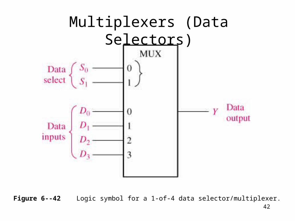
Figure 6--42 Logic symbol for a 1-of-4 data selector/multiplexer.
Multiplexers (Data Selectors)

43

44
Figure 6--43 Logic diagram for a 4-input multiplexer.

45
Figure 6--44

46
Figure 6--45 Pin diagram and logic symbol for the 74HC157A quadruple 2-input data selector/multiplexer.

47
Figure 6--46 Pin diagram and logic symbol for the 74LS151 8-input data selector/multiplexer.

48
Figure 6--47 A 16-input multiplexer.

49Figure 6--48 Simplified 7-segment display multiplexing logic.

50
Figure 6--51 A 1-line-to-4-line demultiplexer.
Demultiplexers

51Figure 6--52

52Figure 6--53 The 74HC154 decoder used as a demultiplexer.

53
Figure 6--54
Parity Generators/Checkers

54
Figure 6--55 The 74LS280 9-bit parity generator/checker.

55
Figure 6--61 Typical configuration for conventional PLD programming.
Programmable Logic

56
Figure 6--62 Flow chart of an SPLD conventional programming sequence.

57
Figure 6--63 Typical configuration for in-system programming of a PLD.