01.pdf · RFP Request for Proposal RT Radiographic Testing RVSS Random Vibration Stress Screening...
117
1
-
Upload
vuongkhanh -
Category
Documents
-
view
216 -
download
1
Transcript of 01.pdf · RFP Request for Proposal RT Radiographic Testing RVSS Random Vibration Stress Screening...

1
2
3
4
CONDITIONS OF RELEASE 1. This Document has been prepared and issued to enable all stakeholders to have the same understanding and appreciation of various facets of Quality Assurance cover provided by the Naval Directorates of DGQA. The provisions of this document are for guidance of and compliance by all concerned. 2. This Document is DGQA copyright and the information therein may be subjected to DGQA and Indian Navy rights. 3. It is pertinent to mention that meeting the QAP requirement does not guarantee the desired output from the equipment which is associated with the designing of the equipment. However, meeting the QAP does guarantee conformance to approved drawings. 4. This document refers to only Quality Assurance Plan to be adopted during manufacturing processes and in no way absolve either the supplier or the user from statutory obligations relating to health and safety at any stage of manufacture or use. 5. Unless otherwise specified, a reference in this document means the issue and all the amendments to that document current on the date of reference. 6. As the provisions of this document is for compliance,any ambiguity or differences in perceptions between two agencies are to be referred to Headquarters, DQAfor clarification. 7. This document is not to be released, reproduced or published without written permission of directorate of quality assurance (DQA). 8. DQA Reserves the right to amend or modify the contents of this publication without consulting or informing any holder.
5
FOREWORD 1. The Directorate of Quality Assurance (Warship Project) [DQA(WP)] and Directorate of Quality Assurance (Naval) [DQA(N)] are two of the 13 Directorates functioning under the Director General of Quality Assurance (DGQA) in the Department of Defence Production, Ministry of Defence, Government, of India. The Quality Assurance responsibility of ‘Mission Critical Equipment’ of Indian Naval Warships such as Main Propulsion, Power Generation & Distribution, Shafting Line, Steering Gear & Stabilizer, Controls & Instrumentation, Water Generation, Compressors, Pumps, HV Air Conditioning & Refrigeration, STPs, Aviation equipment, Winch, Underwater Valves, Weapons/sensors, Electronic/Electrical Defence stores, Navigational Aids etc has been vested with DQA by the Indian Navy. This onerous task is carried out by DQA through their 27 field establishments across the country, which provide Quality Assurance cover for all types of Marine Engineering & Hull Machinery (including associated electrical/electronic equipment/ control systems), Weapons/sensors, Electronic/Electrical Defence stores, Navigational Aids and spares being procured against Purchase Orders placed by Defence Shipyards, Naval Procurement Agencies, Coast Guard and DRDO, both for warships under construction and in commission. 2. This document, christened as Quality Assurance Document (QAD), will be applicable to all procurements, for the above stake holders, for which the QA cover is provided by DQA. The process has been evolved based on internationally followed norms, experience gained by the Indian Navy over six decades of operation and the infrastructure available within the country. It is a comprehensive document, summarising all the policies in vogue, and whilst few aspects have been amplified to bring in clarity, this document has no changes with respect to existing norms. It is envisaged that adherence to the QAD will enable the Industry to manufacture equipment that conform to the requirements of warship applications which are inherently more exacting than those found in commercial or land based applications. 3. With the technological advancements making inroads rapidly, it would be the endeavour of HQ DQA to keep abreast of future developments in Quality Assurance methodology and practices which may bring about changes to the concepts and procedures envisaged and revise these guidelines from time to time. New Delhi (AK Dutta) Rear Admiral 03 Apr 17 Addl Director General
Quality Assurance(Warship Project)

6
Contents Introduction .................................................................................................................. 12
Pre-Requisites .............................................................................................................. 14
Drawings ...................................................................................................................... 16
Quality Assurance Plans .............................................................................................. 20
Outsourced Components/Items .................................................................................... 24
Inspections, Tests and Trials ........................................................................................ 28
Documentation ............................................................................................................. 34
Preservation & Packaging ............................................................................................ 36
Inspection Note ............................................................................................................ 38
Jurisdiction ................................................................................................................... 40
Conflict Resolution ....................................................................................................... 42

7
List of Appendices
Appendix No.
Description Page No.
A Procedure for drawing approval for QA Cover of first time induction Systems and Equipment
41
B Applicability of Approved drawings 45
C Submission of Drawings for Replenishment Orders of Equipment / Spares
47
D Applicability of Approved QAPs 49
E Details of Acceptable Import Documents 51
F Sample ESS Plan 55
G Environmental Test Specifications 61
H Factory Acceptance Trials 65
J Division of Responsibility between DQA(N) and DQA(WP)
67
K Geographical Jurisdiction of Field Establishments 73
List of Annexure
Annexure No.
Description Page No.
I Sample of GA drawing with DBOM 75
II Guidelines for preparation of GA drawings 81
III Thermal Cycle Stress Screening Plan 85
IV Random Vibration Stress Screening Plan 87
V ESS Stress severity Plan 89
VI INShock policy 91

8
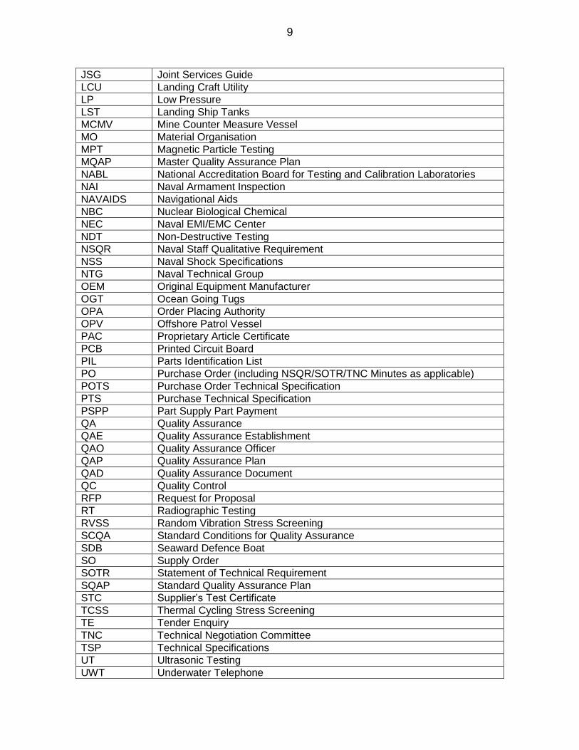
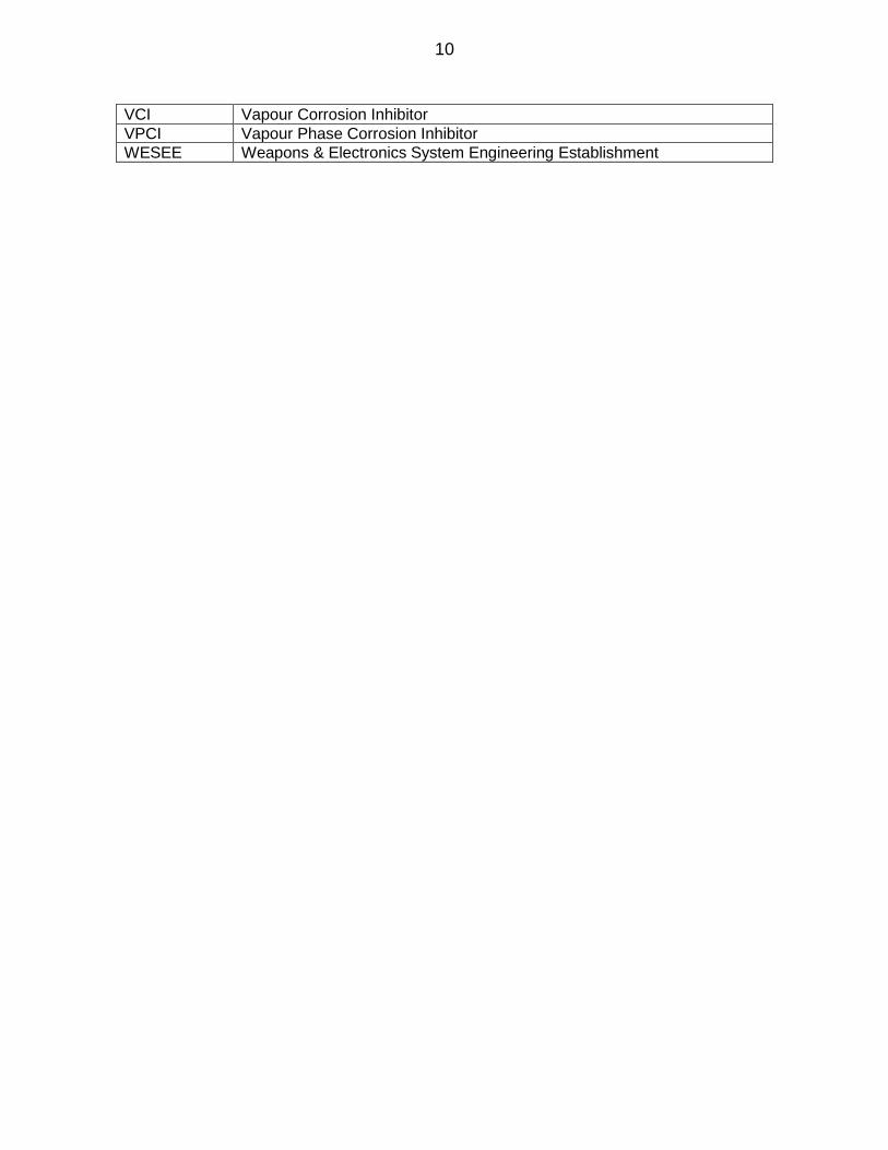
ABBREVIATIONS USED
AIS Action Information system
APMS Automatic Power Management System
ASNT American Society for Non-destructive Testing
ASW Anti Submarine Warfare
ATP Acceptance Test Procedure
AVR Automatic Voltage Regulator
BOM Bill of Material
CDA Controller of Defence Accounts
CHP Customer Hold Point
CNC Contract Negotiation Committee
CoC Certificate of Conformance
COMINT Communications Intelligence
COO Country of Origin
COTS Commercially Off the Shelf
CPRO Controller of Procurement
CQAE Chief Quality Assurance Establishment
CQAO Chief Quality Assurance Officer
DBOM Detailed Bill of Material
DGS&D Director General of Supply and Disposals
DMDE Defence Machinery Design Establishment
DP Delivery Period
DPM Defence Procurement Manual
DPT Dye Penetrant Testing
DPRO Directorate of Procurement
DQA Directorates of Quality Assurance (includes both DQA(WP) and DQA(N))
DQA(N) Directorate of Quality Assurance (Naval)
DQA(WP) Directorate of Quality Assurance (Warship Project)
ECDIS Electronic Chart Display and Information system
EMI / EMC Electromagnetic Interference / Electromagnetic Compatibility
ET Environmental testing
ESS Environmental Stress Screening
EW Electronic Warfare
FAC Fast Attack Craft
FATs Factory Acceptance Trials
FCL First Contact Letter
FCS Fire Control System
FD Forced Draught
FFF Form, Fit and Function
GA General Arrangement
GMDSS Global Maritime Distress and Safety System
HP High Pressure
IFF Identification of Friend or Foe
IHQ,MoD(N) Integrated Headquarters of Ministry of Defence (Navy)
IN Indian Navy
INCO International Commercial
I – Note Inspection Note
ISNT Indian Society for Non-destructive Testing
9
JSG Joint Services Guide
LCU Landing Craft Utility
LP Low Pressure
LST Landing Ship Tanks
MCMV Mine Counter Measure Vessel
MO Material Organisation
MPT Magnetic Particle Testing
MQAP Master Quality Assurance Plan
NABL National Accreditation Board for Testing and Calibration Laboratories
NAI Naval Armament Inspection
NAVAIDS Navigational Aids
NBC Nuclear Biological Chemical
NEC Naval EMI/EMC Center
NDT Non-Destructive Testing
NSQR Naval Staff Qualitative Requirement
NSS Naval Shock Specifications
NTG Naval Technical Group
OEM Original Equipment Manufacturer
OGT Ocean Going Tugs
OPA Order Placing Authority
OPV Offshore Patrol Vessel
PAC Proprietary Article Certificate
PCB Printed Circuit Board
PIL Parts Identification List
PO Purchase Order (including NSQR/SOTR/TNC Minutes as applicable)
POTS Purchase Order Technical Specification
PTS Purchase Technical Specification
PSPP Part Supply Part Payment
QA Quality Assurance
QAE Quality Assurance Establishment
QAO Quality Assurance Officer
QAP Quality Assurance Plan
QAD Quality Assurance Document
QC Quality Control
RFP Request for Proposal
RT Radiographic Testing
RVSS Random Vibration Stress Screening
SCQA Standard Conditions for Quality Assurance
SDB Seaward Defence Boat
SO Supply Order
SOTR Statement of Technical Requirement
SQAP Standard Quality Assurance Plan
STC Supplier’s Test Certificate
TCSS Thermal Cycling Stress Screening
TE Tender Enquiry
TNC Technical Negotiation Committee
TSP Technical Specifications
UT Ultrasonic Testing
UWT Underwater Telephone
10
VCI Vapour Corrosion Inhibitor
VPCI Vapour Phase Corrosion Inhibitor
WESEE Weapons & Electronics System Engineering Establishment

11
RECORD OF AMENDMENTS
Sl. No.
Date of Amendment
Amendments Authority Remarks
12
Chapter 1
Introduction 0101. Engineering and Hull equipment and machinery, including their associated electrical equipment like motors, starters, control panels, control systems, Weapons/sensors, Electronic/Electrical Defence stores, Central Naval Stores and their spares being supplied for installation/use onboard Indian Naval ships and submarines are required to pass through Quality Assurance norms/inspections in accordance with the provisions contained in this document. 0102. An order can be for a system, equipment or spares. For clarity and uniform understanding by all stake holders, these are defined as under:-
(a) System. System refers to any combination of equipment inter connected through pipes, cables, wires, belt, hanger, couplings etc and designed to perform as a composite unit to meet an intended and pre-defined performance; like Air Conditioning System, Propulsion System, Power Generation System, Navigation System etc. (b) Equipment. Equipment refers to a combination of assemblies, sub-assemblies and components which are inter connected and linked together to independently perform a specific and defined function within any system; like pump, diesel engine, air compressor, motor, generator, valve, heat exchanger, radar, antenna etc. (c) Spares. Following will be constituted as spares:-
(i) Assemblies. These are parts of equipment and are combination of components that would constitute standalone functional equipment by itself; like turbo chargers, engine driven pumps, relief valves etc. (ii) Sub-assemblies. These are also combination of components but would not constitute any standalone functional equipment by itself; like rotor assembly, tube stack assembly, impeller assembly etc. (iii) Independent and individual components
0103. The vendor, at any point from receipt of RFP/TE, may seek clarifications on QA related aspects from the concerned Inspection Agency, [the local Quality Assurance Establishment (QAE)] or the Inspecting Authority [Directorate of Quality Assurance (Warship Project) (DQA (WP)/Directorate of Quality Assurance (Naval) (DQA (N)], if required. Contact details of various QA agencies are available at the DGQA website (http://www.dgqadefence.gov.in).

13
0104. In case of equipment covered under dual inspections by Class and DQA(WP)/DQA(N), QA coverage according to approved QAP by DQA(WP)/DQA(N) is mandatory. Inspection note from QAO will be mandatory for equipment and will be issued post completion of all inspection stages as per DQA(WP)/DQA(N) approved QAP. The vendor may associate the Class whilst QAO is undertaking inspection for economy of efforts. 0105. The vendor is to contact the inspecting agency within five working days of the receipt of purchase order to initiate Quality Assurance Cover. The First Contact Letter (FCL) from respective CQAE/QAE to vendor will be issued on receipt of purchase order; either from OPA (by email or post) or from Vendor. A meeting is to be held between the vendor and QAO at the earliest opportunity, but not later than seven working days of first contact with the QAO. A copy of minutes of this meeting is to be forwarded to the Order Placing Agency and Inspecting Authority clearly mentioning the timelines for submission of various documents by the vendor and plan of action to execute the order within the delivery period. Failure to adhere these provisions and the schedule drawn up will result in downgrading of the vendor rating. 0106. Manufacturing is to commence only on availability of approved QAP issued by the Inspecting Authority.
14
Chapter 2
Pre-Requisites 0201. Quality Assurance cover is provided by the Inspecting Authority, through the local Inspecting Agency only when the Purchase Order mandates and authorises the Inspecting Authority and the specific Inspection Agency to provide the QA cover. The pre-requisites for undertaking QA inspections are as follows:-
(a) A valid Purchase Order (PO). (b) Complete set of drawings, approved by designated agencies as provided at Chapter 3.
(c) QAP approved by the Inspecting Authority and valid for the instant PO. (d) Acceptance Test Plan (ATP)
0202. Each of the equipment/item mentioned in the PO should be unique and traceable by unique part no and/or unique drawing/s. 0203. Conformity of the details provided in the PO and those submitted by the firm viz. Part IIIustration List (PIL), approved OEM documents etc. Quality Assurance (QA) cover will be provided with respect to the specifications in the Purchase Order and any mismatch of details will obviate further progressing of QA cover. 0204. Necessity for type testing and qualification testing (like shock testing, specific environmental tests, EMI/ EMC tests, endurance trials etc) are to be clearly indicated in the PO. All electrical equipment (Weapons/sensors, cable, electronic systems, motors, starters & control panelsetc)and mechanical equipment/systems (Pumps, engines, valves, compressors etc) are mandatorily required to be type tested, if not done earlier. The nature and type of tests will vary depending on the equipment and system and will be specified in PO. 0205. Requirements of FATs should be specified in the PO. 0206. Irrespective of the quantum, any change in material, design, duty point, manufacturing process, sourcing, governing standards/specifications (view obsolescence/ revision etc), with respect to supplies made earlier will be construed as ‘Change’, requiring revision of drawings and/or QAP including qualification/type testing.

15

16
Chapter 3
Drawings 0301. The drawings are to have all details as necessitated to ensure compliance to the requirements of the PO and are to be in compliance with BIS-SP 46-2003. 0302. The drawings for induction/shipyard orders are to be approved in accordance with the procedure placed at Appendix ‘A’, by authorities as under:-
(a) By Professional directorate for compliance to NSQR/ SOTR. (b) By Production directorate wrt to installation (c) By Inspection Authority wrt to Quality Assurance
0303. The process flowchart for approval of drawings is depicted in figure 1.
Fig. 1: Process flowchart for approval of Drawings.
17
0304. Applicability of drawings, including for repeat or replenishment orders placed by shipyards and/or Navy (IHQ,MoD(N)/MOs) will be governed by the provisions provided at Appendix ‘B’. Details and methodology for submission and reference of drawings for replenishment orders are placed at Appendix ‘C’. Repeat/Replenishment orders for system/equipment those have been inducted into the Navy through third party/class QA cover in the past will be treated as first time inductions for the purpose of QA cover through DGQA. 0305. All previously approved drawings and QAPs being used is to be the latest approved version available, irrespective of the fact that the present equipment/item in use has been accepted against a previous version. Similarly, all governing standards and specifications will be of the latest revision/edition irrespective of the fact that the present equipment/item in use has been accepted against a previous version.
0306. Irrespective of the quantum, any change in material, design, duty point, manufacturing process, sourcing, governing standards/specifications (view obsolescence/ revision etc), will be construed as ‘Change’, requiring revision of drawings and/or QAP including qualification/type testing. 0307. In cases where detailed drawings are to be submitted in accordance with the provisions at Appendix ‘B’, the drawings should be submitted as a complete set with GA drawing and Manufacturing drawings (sub assembly/component drawings, Component Layout Drawing, Wiring Chart, Cable Schedule, Connector Details etc), with both mutually identified and duly linked with one another. 0308. The detailed/component drawings, irrespective of being submitted for approval or presented at site for inspection, should include (may not be limited to) the following:-
(a) Dimensions and units
(b) Tolerances (c) Main Assembly/ Sub Assembly details
(d) Bill of Materials/Part Identification List (PIL) along with Material Specifications including grade, condition and specification number, “Make” & “Model” in case of COTs items. (e) For Sub Component Drawings, correlation details with the PIL & Main Assembly Drawing (f) Packaging & Preservation details (g) Weight with tolerance
18
(h) Working/Test Pressures and working medium/testing medium (j) Applicable Specification Number (along with the No of Version and Year of Publication) (k) Product specific testing requirements and acceptance norms thereof (l) NDT zones and Quality level of NDTand acceptance norms thereof (m) ET/ESS and Type test requirements (n) Weld details and acceptance norms thereof
(p) Manufacturing process/process flow chart for major components (q) Painting Procedure with specifications
0309. In addition to above, for electrical system drawing, following are considered
mandatory:-
(a) Schematic diagram indicating inter-panel connectivity.
(b) The GA drawings that will establish the physical disposition of panels wrt
each other.
(c) The GA drawings of sub units along with DBOM and relevant reference for
wiring chart/cable schedule and component layout drawings.
(d) The DBOM is to form the basis of PIL up to component level and both BOM and PIL should map one to one as in case of mechanical items.
0310. Drawings should also clearly indicate items/components/sub-assemblies that are imported, bought out and COTS along with full details thereon. This should include the source of procurement/import, the model and the make of the bought out/COTS items. In case of electronic modules fabricated/assembled indigenously with imported/bought out components, requisite information to ensure quality and traceability is to be provided. 0311. The size of drawings presented are to be such that all indicated parts are clearly and unambiguously identifiable with a minimum letter fond size of Arial 10, subject to minimum A4 size.

19

20
Chapter 4
Quality Assurance Plans 0401. The QA cover will be provided in accordance with the approved QAP issued by the Inspecting Authority. For each Purchase Order (PO), either the approved QAPs will be specified in the PO or a new QAP will be drawn and approved afresh. 0402. Standard Quality Assurance Plans (SQAPs) have been formulated with participation of all stake holders and promulgated for some systems/equipment. In some other cases, an existing approved QAP may be applicable with or without changes. In all other cases, QAP is to be drafted by the manufacturer, taking reference of following documents (uploaded at http://www.dgqadefence.gov.in) (The documents under reference are to be taken for guidance only and the various tests and other requirements of quality assurance will be governed by the QAP as approved by the Inspecting Authority based on PO/Purchase Technical Specification/TNC Minutes.):-
(a) Guidelines for Quality Assurance for Engineering and Hull equipment for Indian Naval Warships (b) Generic QA guidelines for Electrical/Electronic equipment (c) Various Master Quality Assurance Plans (MQAPs) (d) QAPs issued previously
0403. The approved QAP could be an SQAP or a previously approved QAP or a new QAP. The applicability of the QAP will be as per the provisions placed at Appendix ‘D’. 0404. The QAP is to cover all components, sub-assemblies and full assemblies including motors, control panels, consoles etc.
0405. The formulation and approval of QAPs for various types of order/procurements will be governed by the provisions enumerated in succeeding paragraphs. 0406. For a system/equipment for which SQAP has been issued, only the relevant SQAP is acceptable. Formal approval to use the QAP will be accorded as under:-
(a) Where SQAP for the instant system/equipment has been issued, uploaded and available with RFP/on the DGQA website on the day of submission of offer by the firm, the relevant SQAP will be the approved QAP for the instant order.
(b) In case the instant supply has components and/or process not covered in the SQAP, the firm is to seek clarification and confirmation with respect to inspection aspect and norms of new introductions. The relevant SQAP with these amendments/introductions will then be the approved QAP for the instant order.
21
SQAP will subsequently be amended to incorporate these aspects for future orders.
0407. No other form or variant of QAP will be acceptable for equipment/system for which SQAP has been issued and available. 0408. In cases where SQAP has not been issued and where an existing QAP is to be used, the firm has to make a formal request through the Inspecting Agency. Concurrence for use of the existing QAP with/without changes will be issued by inspecting authority on receipt of request from the firm. Where concurrence has been accorded prior/during CNC/TNC, the PO be issued with the relevant QAP (as amended, if required) as the approved QAP for the instant order. 0409. Where there are changes with respect to last supply, the drawings and/or DBOM needs to be amended and approved as per extant rules. Subsequently, the firm submit its proposed QAP, incorporating changes where required with respect to existing QAP, through the Inspecting Agency to seek approval. It will be imperative that validity of the functional and type tests as per earlier design is ratified by the competent authority without which all functional/type tests as applicable will need to be undertaken for current production. Approval for use of the amended QAP with/without changes will be issued by inspecting authority on receipt of request from the firm. Where approval has been accorded prior/during CNC/TNC, the PO be issued with the relevant QAP as amended as the approved QAP for the instant order. 0410. In case of fresh QAP being drafted by the firm, it should conform to provisions of MQAP and/or latest version of approved QAPs issued earlier where applicable. Whilst existing QAP for same/similar equipment/item supplied earlier can be taken for guidance, any changes required in terms of addition/deletion of tests or modifications that has been necessitated view lessons learned and/or technological advancements needs to be verified and confirmed from the inspecting authority prior undertaking any manufacturing activity.
0411. All queries with regards to using an existing QAP, with or without changes or submission of a draft QAP for fresh approvals are to be through the local QAO for final approval by the Inspecting Authority. Since the QAP flows from the PO and drawings therein, all queries and draft QAP shall be forwarded/submitted along with PO and references/approved drawings, as per the provisions placed at Appendix ‘B’. 0412. DQA and their field units will provide required clarifications and confirmation on applicability and/or validity of relevant SQAP/previously approved QAP for a system/equipment/item as and when the relevant details like previous purchase order, I-Note reference, equipment/item specifications like drawing no and approved QAP etc are provided, even during the indenting or tendering stage. In addition, an intending supplier can also seek these clarifications on receipt of tender enquiry and before submitting the offer, if it so desires. All such clarifications are to be sought through the concerned local QAO under intimation to OPA and Inspecting Authority. The inspecting
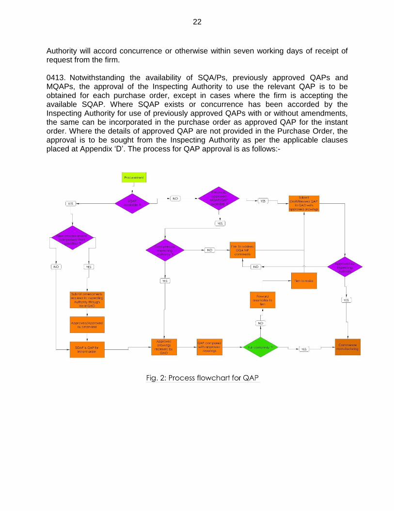
22
Authority will accord concurrence or otherwise within seven working days of receipt of request from the firm. 0413. Notwithstanding the availability of SQA/Ps, previously approved QAPs and MQAPs, the approval of the Inspecting Authority to use the relevant QAP is to be obtained for each purchase order, except in cases where the firm is accepting the available SQAP. Where SQAP exists or concurrence has been accorded by the Inspecting Authority for use of previously approved QAPs with or without amendments, the same can be incorporated in the purchase order as approved QAP for the instant order. Where the details of approved QAP are not provided in the Purchase Order, the approval is to be sought from the Inspecting Authority as per the applicable clauses placed at Appendix ‘D’. The process for QAP approval is as follows:-

23

24
Chapter 5
Outsourced Components/Items 0501. Whilst it is the prerogative and mandate of the vendor to manufacture or source manufactured components as deemed necessary, it is imperative that the information is provided in the approved drawings to facilitate smooth QA cover. The mode of sourcing is to be indicated in the approved drawing/DBOM explicitly. QA cover for the components which are manufactured in-house will commence with raw material inspection, go through in process inspections, testing & trials as necessary and culminates with inspection of preservation & packing and final dispatch clearance. QA cover for components which are sourced from other manufacturers/vendors (outsourced components/items) will be provided in accordance with the provisions provided in succeeding paragraphs. 0502. The following will be construed as outsourced components:-
(a) Imported Items (b) Commercially Off The Shelf (COTS) items (c) Bought out items (d) Sub contracted items
0503. Input materials which go for further processing and manufacture like metal plates, billets, stocks, sections, tubes, wires, cables, metallic & non-metallic sheets etc will not be treated as outsourced components. POLs, chemicals, critical components of safety and lifesaving systems etc, though available commercially, will not be considered as outsourced/COTS for the purpose of QA cover.Accordingly, these will be tested for all requirements as necessitated by the governing standards. For some input materials, where the quantities are meager and all tests as per governing standards not feasible/viable, the same may be accepted against STC. However, such instances should be indicated up front, recorded in TNC/CNC minutes or in PO. 0504. Imported items. Imported items are those which are manufactured in a foreign country and imported to India. Imported items will be accepted against import documents as per directives in vogue. Presently the documents to be submitted are as follows:-
(a) Bill of Lading
(b) Country of Origin
(c) Shipping Bill
(d) Bill for entry to warehousing
(e) OEM’s Test Certificate/Quality Assurance Guarantee Certificate

25
(f) OEM’s Confirmation Certificate
(g) Firm’s Guarantee Certificate as per SOs.
0505. Functional tests of imported items may be undertaken in addition, as per guidelines enumerated at Para 0603(c) / Appendix ‘H’ respectively. 0506. To cater for different types of documents issued by different agencies and different formats and formalities across various countries, documents as indicated against each at Appendix ‘E’ will be acceptable as valid documents for providing QA cover for imported items.
0507. COTS items. COTS items cover those items/equipment which are available in the open market, are under the regular production of the firm and can be procured off the shelf without having to give a specific manufacturing order. 0508. COTS/Catalogue items will be accepted on the basis of Suppliers Test Certificate (STC) and/or Certificate of Conformity (CoC) with following conditions:-
(a) Suppliers Test Certificate (STC) is issued by the original manufacturer of the COTS item.Certificate of Conformity (CoC) is issued by the equipment manufacturer or integrator who has sourced the COTS item for use in the equipment. CoC/STC must indicate governing specifications and values to which the item has been tested. The certificate must include copies of test reports. (b) In case of manufacturers certified under relevant quality standards (like ISO, OSHAS etc), the pre published data sheet or company quality policy bringing out the details of test carried out on specific items may be accepted. (c) Indian Navy reserves the right to test a sample out of that supplied, for conformity to desired specification. Failure of the test sample will make the supplier liable for rejection/return of the entire lot. The test may be undertaken by IN anytime during the guarantee period at an accredited lab.
0509. Bought out items. Bought out items are those which are in the general product range of the manufacturing firm, but manufactured on placement of specific order by main firm and production is covered by main firms’ quality control program. Bought out items manufactured indigenously will be subjected through QA inspection unless otherwise specified in the PO. Where bought out items are not subjected to inspections, relevant test certificates/reports and compliance certificate is to be submitted by manufacturer indicating governing specifications and values to which the item has been tested.

26
0510. Sub Contracted items. These are such items/components manufactured by a sub-contractor of the main firm against specific purchase order from the main firm and
with reference and relevance to the PO/TSPs of the main order.
0511. In case parts/components being outsourced, the main firm is required to submit ink/digitally signed copy of sub-order and ensure that the outsourced out items meet the specifications/standard. Subcontract must include the main PO reference and governing specifications clearly as mentioned in main PO. Inspection where required, will be carried out at sub-contractor's premises as per approved drawings/QAP/ATP. 0512. Jurisdiction of QAO for Sub-contracted/bought out items. Where the manufacturer of the sub-contracted/bought out item is not co-located within the jurisdiction of the primary QAO, the QA cover will be provided by the local QAO under whose jurisdiction the manufacturing firm is located, against a sub nomination approved by the inspecting authority. Similarly, for cases of bought out items those have to undergo detailed inspections per approved QAP, sub-nomination is to be adopted in cases where the jurisdiction of main QAO is different. 0513. In cases of sub-nomination, the main vendor will be responsible through the main QAO for providing approved drawings and QAP to the nominated QAO. Once approved drawings and QAPs are received by the nominated QAO, then for all subsequent actions/requirements, including clarifications from the nominated vendor, if any, this nominated case is to be treated at par with a main vendor and main QAO procedure, till issue of I-Note. 0514. All Certificates like STC, CoC, import documents, other test certificates etc should be submitted in original. Traceability of digitally signed documents or e-documents, where applicable and submitted, is to be ensured and shown by the firm for verification.
27
28
Chapter 6
Inspections, Tests and Trials
0601. Inspections relate to those activities undertaken to assure compliance of the process and product to the specifications and standards as provided in the PO and approved drawings/DBOM. 0602. Inspection could include following:-
(a) Raw material inspections which may include witnessing of pouring, forging etc. (b) Destructive tests of samples/test pieces for chemical composition/mechanical properties. (c) Component level (including weldments) Non Destructive Tests (NDT) like RT, UT, DPT, MPT etc to detect surface/sub surface defects and grain boundary discontinuities.
(d) All Castings will be subjected through RT to qualify the same in accordance with the approved Class of Castings, unless otherwise specified in PO or governing standards. (e) Micro/Macro examinations. (f) Dimensional checks before assembly.
(g) Sub equipment/component level pressure testing in addition to NDT for integrity/strength conformity.
(h) Witnessing procedures to ensure compliance to manufacturing plan and traceability of the component.
(j) Inspection/verification of calibration status of measuring instruments/ machinery/other instruments including furnaces/lathes/boring centers etc for Heat treatment/melting/machining etc. (k) Measurement of Structure Borne Noise and/or Air Borne Noise. (l) Recording of Vibration levels. (m) Clearance of Customer Hold Points (CHPs) by the nominated Inspection Agency prior proceeding further with manufacturing, (both for “Witness” and “Review” as per applicability) to obviate rejection at later stage.

29
(n) All tubes/pipes will undergo eddy current test unless exempted per PO.
(p) All forgings will undergo UT for soundness and integrity checks. (q) All electronic components will undergo endurance and burn in test, if not waived off in the PO.
0603. Tests relate to those activities undertaken on completed component, assembly, equipment or system for design validation of specific parameters and performance evaluation. Following tests and trials are undertaken:-
(a) Production tests. These are those tests, as given at para 0602 above, undertaken during the manufacture of each piece/batch as per the approved QAP.This will also include Environmental Stress Screening (ESS). Details of ESS are placed at Appendix ‘F’. (b) Qualification/Type tests. These are those tests undertaken to validate the design and are generally undertaken only on the prototype or first piece/set unless specifically mandated by PO. These include Environmental Testing (ET), EMI/EMC tests and shock testing. Samples of ET specifications are placed at Appendix ‘G’.The EMI/EMC tests will be carried out as per IHQ MoD (N) approved Naval EMI/EMC acceptance Plan (EMI-AP) duly vetted by NEC (MB).
(c) Functional Tests. These are those tests under taken on a component, an assembly or equipment to evaluate the functional capability and capacity, including SBN, ABN and vibration signature of the item under testing. These functional tests are to be carried out in accordance with the Acceptance Test Plan approved by IHQMoD(N) or their authorised agency.Since subjecting an item for functional test may require other components not in present order or supporting infrastructure not catered/envisaged for while placing the order, or not available with the instant vendor/firm on whom the order is placed, there is a requirement to clearly define the applicability of such tests. The following guidelines will be applicable across all types of orders with respect to undertaking of functional tests:-
(i) All equipment/system which are part of first time or induction ordering will undergo functional tests to establish its ability to confirm to specifications and requirements as provided in PO. (ii) All equipment/assemblies like pumps, engines, compressors etc. which are part of even replenishment orders should undergo functional tests unless waived off in the purchase order. It will be the responsibility of the vendor/firm to provide such facility to undertake the functional tests.
30
(iii) All subassemblies and components will need to undergo functional tests if such tests are mandated in the original approved drawings/DBOM. Any wavier for such tests should be mentioned in the PO. (iv) For all other spares where functional tests are not indicated in approved drawings/DBOM, no functional tests will be undertaken, unless dictated specifically in the PO. (v) Where functional tests are destructive in nature like filter elements, electrodes etc, relevant sampling criteria should be specified in PO/Approved drawing. (vi) Where functional tests are not feasible for lack of infrastructure or support facilities, the vendor/firm is to appraise the OPA before submission of offer and seek appropriate directions/orders as applicable. (vii) In general, the functional tests will be operating the equipment to rated load/performance under normal operating conditions. Any other specific regime or requirement like only no load run, partial loading etc should be clearly defined in drawings, tendering/tender response and recorded in the PO.
0604. Trials relate to monitoring the operation and performance of the completed sub-assembly/assembly/equipment/system. Trials validate overall functional performance parameters as per design.These would include following:-
(a) Production/Routine trials – These are trials that each piece/system has to undergo to ensure designed performance. (b) Endurance trials – These are trials during which the equipment/system is operated continuously at pre-determined duty cycles for a pre-defined, extended duration to ensure sustainability of the equipment/system for prolonged operation. The applicability of endurance run to each piece/system or only the pilot case will be governed by the provisions of PO and approved QAP.
(c) Factory Acceptance Trials (FATs) – The requirement for conduct of FATs would be specifically indicated as part of the PO. FATS is the final operational run of the equipment at the manufacturers test bed, in a configuration as close to the actual layout on board, before the equipment is cleared for dispatch for onboard use/installation. Where the deliverables constitute a system, an Integrated FATs is required to be undertaken.Details and modalities of conduct of FATsis placed at Appendix ‘H’.
0605. Environmental Stress Screening (ESS). The ESS, though part of the manufacturing process, plays a vital role in establishing the process and product capability. Guidelines for conducting ESS are placed at Appendix ‘F’.
31
0606. Inspection process for Replenishment/Repeat Orders. Replenishment/ repeat orders can be for complete system, equipment or spares. The inspection process for replenishment orders will be governed as follows:-
(a) Systems and equipments will be inspected in accordance with relevant QAP and associated approved drawings as undertaken for induction orders. Type tests, qualification tests, endurance trials etc will be governed by the provisions of purchase order. Where these are not explicitly mentioned in the PO, type tests, qualification tests and endurance trials will be undertaken only if relevant type test, qualification test and endurance trial have not been undertaken earlier or there are changes with respect to the system/equipment that had undergone these trials earlier. (b) Spares sourced from non-PAC firms will be subjected to complete QA/inspection process as warranted by the approved QAP/drawings up to the component level.
(c) In respect of spares where inspection clause per PO is “As per OEM Tech
Spec”, inspection/QA cover will be governed as follows:-
(i) The inspection will be undertaken in accordance with specification/details provided in the DBOM/Approved PIL. (ii) If specifications/sufficient details are not indicated in PIL, the details provided in the drawings as indicated in DBOM/submitted by firm will be taken as reference. (iii) Inspection will cover conformance to material specifications, manufacturing process and dimensions. Material specifications will be against STC and others will be verification of certificate of conformity issued by the firm. Physical verifications of dimensions will be undertaken for binding/critical dimensions. (iv) Type testing/qualification tests where necessary, will be undertaken if not undertaken earlier or if relevant test certificate is not available with the firm or if the item has any changes. (v) All routine/functional tests that are part of ATP as per Specifications/original induction QAP will be undertaken unless specifically waived off by the OPA.
0607. Further, all tests/trials are to be undertaken at NABL accredited laboratory, under intimation to the concerned QAO. In cases where testing is accepted to be undertaken at facilities which are not accredited by NABL, witness of testing by QA agency is
32
mandatory. Sentencing/interpretation of all NDT tests like RT, UT, MPT, DPT etc should be provided by a technician qualified in ISNT/ASNT level II in the relevant discipline. 0608. The QAO will attend to various stages of inspections on receipt of inspection call from the vendor. Whilst a broad production schedule indicating likely period of inspection calls is to be prepared and handed over by the firm to local QAO on receipt of FCL, a formal request for specific inspection is to be made at least three working days for inspection in station and seven working days for inspection out of station. Urgent cases may be mutually worked out between the firm and QAO. Details of internal QC inspections and reports of the firm are to be provided along with the inspection call letter.
0609. In some cases, considerable time lapse is observed between the inspection of a particular sub-assembly and its integration with the main equipment. In such cases, the validity of QA inspection of the sub-assembly becomes suspect due to considerable lapse of time from its inspection. There fore, the shelf life of every component or assembly cleared is to be indicated after completion of inspection. Only components/ assemblies within the valid shelf life are to be taken up for assembly/integration in/with the main equipment/system. The vendor will provide details of any life-limited item, included as part of the equipment/ assembly/ sub-assembly, as part of the Inspection Process. 0610. Inspections will be undertaken only within the currency of delivery period. In exceptional cases, where delivery period has expired, the Inspection Agency may consider extending the QA cover and continue with inspections on request from the vendor/firm subject to the firm having taken up the case for delivery date extension with the OPA. However, since Inspection note/Form IV can be issued only within the currency of delivery period, in such cases, the I-note/form IV will be issued only after the delivery period is extended by the OPA. The Inspection Agency proceeding with the QA cover despite the expiry of the delivery period will not entitle the firm to any claims or guaranteed acceptance of the item/equipment by the OPA nor will it bind the OPA to provide delivery extension. Such inspections will be at the sole risk and responsibility of the vendor/firm. The validity of such inspection is only 30/60 days without/with revalidation. Therefore, DP extension is to be made available before the expiry of this period, failing which the validity of inspections undertaken will expire precluding issue of I-note.
0611. In accordance with the provision of article 7.9.1 of DPM 2009, “In certain cases where the contractor offers stores for inspection during the last few days of contract DP or on the last day of contract DP, the inspector can inspect the store and sentence it as per standard franking clause”. In such cases, units will undertake inspection of equipment and stores only where the inspection call has been made and I-note will be issued mentioning that the inspection has been completed in accordance with clause 7.9.1 of the DPM 2009.

33
0612. After the I-note is issued, the item has to be dispatched in accordance with the INCO Terms specified in the PO. In case of non-dispatch within 30 days period, another 30 days of grace period is provided. However, for dispatch during the grace period, the I-note needs to be revalidated. After 60 days, the items have to be re-offered for inspection.

34
Chapter 7
Documentation 0701. In some cases, particularly induction/shipyard orders, the deliverables also include documents like technical description, operating manuals, PIL, maintenance manuals etc. 0702. For POs which include documentation as deliverables, I-note/Form IV will be issued only on completion of the contractual obligations per PO.
0703. Notwithstanding any provisions for submission of final documentation de-linked from issue of I-note/form IV, and for cases where documentation is to be approved by IHQMoD(N) or another third party, and the final document can be produced only after the FATs, the draft documents needs to be submitted as a pre-requisite for final dispatch clearance.
0704. For equipments/systems that are to be subjected to FATS, the draft operations
manual is to be made available prior raising request for conduct of FATS.
0705. For Electrical/Electronic and weapons/sensors, clearance certificates from NTG
will form the basis for acceptance of documents as part of deliverable.
35
36
Chapter 8
Preservation & Packaging 0801. Preservation and packing is the last process before the equipment is cleared for dispatch from the factory to the consignee. Since the equipment or the spare is put to use much later, is imperative that adequate preservation is provided and that the items are suitably packed and delivered safely to the consignee. The measures to be complied with are as follows:-
(a) The medium and mode of preservation is to be unambiguously spelt out in the binding/ GA drawing with any additional specific requirement at the component level in the DBOM. The protection and preservation could include painting, electroplating, vacuum packaging, encapsulating with VCI/VPCI, shrouding etc. (b) Specific procedures are to be provided in the drawing along with the specifications and standards as applicable and mentioning generic conditions like ‘standard commercial packing’ etc are not acceptable.
(c) The preservation process is to commence immediately on completion of the last inspection procedure. Particular emphasis is to be paid to sealing/closing of open ends immediately on completion of relevant tests; including during in process inspection to obviate ingress of any sort of contaminants. Suitable preservation of all electrical and electronic contacts, consoles and items are also to be undertaken immediately after the inspection process.
(d) The packing list providing details of items are to be enclosed with the package.
(e) Suitable tally providing the consignment and consignee details should be placed prominently on the package.
(f) The following additional details are also to displayed prominently on the packing:-
(i) The life of preservation(Re-preservation due on -------------) (ii) Any periodic inspection or maintenance required. (iii) Any special or specific handling and transportation requirement. (iv) Storage requirement in warehouse.
(v) Use before ------------- in case of items with shelf life

37
38
Chapter 9
Inspection Note 0901. The programme of Quality Assurance culminates in issuing a document, generally termed as Inspection Note (I-Note) that clears the item or equipment for acceptance and dispatch.
0902. Two formats have been promulgated for Inspection Note as mentioned below:-
(a) DGS&D(S) – 84 Form – These are Inspection Note issued for orders placed by any agency or organisation except shipyards and sub–orders. This form is entirely filled by the Inspecting Agency. The payment cases under this form of I-note are processed through CDA for orders placed by Indian Navy. (b) Form 4 – These are issued when an item is inspected for which the order was placed by a shipyard or in case the item is a part of a sub–order. In this case, the firm fills up the form and submits the same to Inspecting Agency for approval and issue. The payment cases under this form of I-note are not processed through CDA.
0903. The issue of Inspection Note (Form 4 / DGS&D(S) – 84 Form) by Inspection Agency primarily certifies that:-
(a) The component or equipment has been inspected in accordance with approved QAP and drawings. (b) The requirements stated in the Purchase Order have been met; with approved concessions or deviations if any.
0904. The Inspection Note reflects the acceptability of the ordered goods at the point of despatch. In case the equipment or part is damaged during transit, the applicable clauses of insurance, guarantee and warranty will be invoked. 0905. The Inspection Note is a document having financial implications. Hence all regulations and orders in force should be strictly adhered to. The salient features are:-
(a) The Inspection Note will be issued only after all inspections have been completed, including that of documentation, preservation and packing. (b) The number of Inspection Notes in each order will not exceed the total number of Part Supply Part Payment (PSPP) clause mentioned in the Purchase Order.

39
(c) During issue of I-Note for part quantities, the rules for painting, preservation, packing and shipment will be applicable at par with the complete equipment and there shall be no concessions. (d) The Inspection Note will be issued only if the delivery period is valid. (e) The Inspection Note can be signed by authorised officers only.
(f) The inspection note will be issued within 07 working days of meeting all requirements.
0906. No Certified True Copy or duplicates of the Inspection note will be issued as a routine. If specifically sought by the firm or Order Placement Authority, a certificate from Purchasing Agency stating “No payment has been made against the lost Inspection Note and no payment will be made against the original document if retrieved”, has to be submitted along with the request for issue of a duplicate Inspection Note. The extant rules will be rigidly adhered to.
0907. A Vendor rating of the firm will be an integral part of all I-notes. Vendor rating is an indexed grading of the performance of the firm with respect to instant order and will cover attributes such as quality of process, quality of product and adherence to timelines. Lower vendor rating could result in de-registration or capacity de-valuation of the firm in accordance with provisions of JSG - 07.
0908. For equipment covered under Dual Inspection, Inspection note from QAO will be
mandatory and will be issued post completion of all inspection stages as per
DQA(WP)/DQA(N) approved QAP. Similarly, in case of inspection of weapon items
where few components will be inspected by Naval Armament Inspection (NAI), DQA(N)
will remain the primary QA authority while NAI will issue Inspection Clearance
Certificate to vendors for components falling under their purview. I-Note will be issued
by DQA(N) on completion of all QA activities as per QAP and receipt of clearance
certificate from NAI as well as NTG for documentation.
0909. Despatch Clearance. Under special circumstances, where part quantity not covered in the PO or in very rare occasions where the complete system is required at the consignee urgently and before the I-note/form IV can be issued, the OPA may seek approval for despatch clearance of the inescapable quantities to meet the immediate requirement. The approval for despatch clearance will be accorded by the Inspecting Authority on a case to case basis, provided all QA activities are completed. However, I-note/form IV will be issued only after all requisites are met and available. This facility is to be used only as an exception. Such despatch clearance does not entitle the firm to seek issue of I-note/form IV till all pre-requisites are otherwise met. Such clearances will be at the sole risk and responsibility of the vendor/firm to fulfill all the mandatory obligations for issue of I-note/form IV.
40
Chapter 10
Jurisdiction 1001. The DQA organization provides quality cover for a wide range of equipment and systems through the various field units located across the span of the country. In order to have absolute clarity with respect to the inspecting authority and inspection agency, clear demarcation of responsibilities with respect to functional jurisdiction and geographical jurisdiction have been made and is enumerated in succeeding paragraphs. 1002. The inspecting authority for an equipment/system will be in accordance with the demarcation of the responsibilities between DQA(WP) and DQA(N) as placed at Appendix ‘J’ 1003. Inspection agency will be based on the functional jurisdiction with respect to Inspecting Authority and the geographical jurisdiction of the Inspection Agency. The geographical jurisdiction of various inspecting agencies is placed at appendix ‘K’. 1004. The inspecting authorities also reserve the right to nominate a different inspection authority or inspection agency, considering core competence and work load. Such cases will be taken up with the OPA as required. 1005. The purchase orders are to indicate the inspecting authority and the inspection agency in the purchase order. Any requirement for change or amendment to the same will be taken up by the nominated inspection agency through its inspecting authority.

41
42
Chapter 11
Conflict Resolution 1101. The Quality Assurance process is an intense and iterative process involving many stakeholders, viz. the OPA, production and professional directorates/Command Headquarters, the Inspection Authority/Agency and the vendor/manufacturer. Therefore, there is bound to be differences in perceptions and these are to be resolved as provided in succeeding paragraphs.
1102. Authority to approve and/or amend QAP is the Inspecting Authority. For systems/equipment for which SQAPs have been issued with the participation of the various stakeholders, deviation from SQAP will be accepted only in exceptional cases like change in process, sourcing etc. Any request/case with respect to the QAP in so far as the specifics of QAP are concerned is therefore to be referred to the Inspecting Authority through the nominated Inspection Agency.
1103. Authority to specify/amend the governing parameters including specific standards, grades, qualification/type test requirements, limiting parameters, indication of list of COTS equipment/ module/ sub-assembly etc will be the OPA. The Inspection Agency will accept the product/process only when they are within the prescribed limits as per the specifications provided in the PO. Any request/case with respect to changes/amendments to the governing standards/specifications or parameters is therefore to be referred to the OPA under intimation to the Inspecting Authority and the nominated Inspection Agency.
1104. Concessions and Deviations will be governed as per the provisions in Chapter 13 of Guidelines for Quality Assurance for Engineering and Hull equipment for Indian Naval Warships.

43
44
Appendix ‘A’
(Refers to Para 0302)
PROCEDURE FOR DRAWING APPROVAL FOR QA COVER OF FIRST TIME INDUCTION SYSTEMS AND EQUIPMENT
1. Submission of Drawing. The firm to submit the GA drawings with respect to the system and/or the equipment under procurement containing the layout, boundary/ installation parameters/dimensions and a detailed bill of material (DBOM). 2. If the main or subsequent GA drawings have assemblies and subassemblies in their BOM, GA drawings of these assemblies and subassemblies along with their DBOM will also need to be submitted. Thus, all assemblies, subassemblies and parts constituting the system and equipment should get reflected in the GA drawings and DBOM submitted, duly linked in a parent child relation that will ensure forward and backward traceability.
3. Manufacturing Drawing. The manufacturing or detailed drawings will remain with the firm, to be produced to the QA team during the visit for inspection. 4. Detailed Bill of Material. Each GA drawing is to have its associated DBOM. Specifications and parameters which ensures that the product will meet the requirements of PO and which are required to draw up QAP are to be provided in the DBOM. While providing the details in the DBOM, following are to be included:-
(a) Drawing no of each assembly, sub assembly and component indicated in the drawing (b) Material specifications including grade/condition (c) Manufacturing process (including heat treatment and stress relieving diagram where applicable) in case of major, critical, loaded and stressed components.
(d) Components where specific testing and examination like RT, UT, MPI, DP etc are required with the corresponding drawings depicting shooting sketch and inspection norms and acceptance criteria for the specific BOM (can be schematic without dimensional, or manufacturing details). (e) Requirement of type testing, functional testing etc in respect of assemblies and subassemblies (f) Areas of Critical dimensions, weights and tolerances (Values and limits need to be indicated in the manufacturing drawing only)

45
(g) Interfacing requirements of mating components
(h) In case of COTS, Imported and bought out items, the details like make and model, country of origin etc.
5. This DBOM is to form the basis of PIL and both DBOM and PIL should be mapped one to one. Sample of GA drawing with DBOM and guidelines for preparation of GA drawings are placed at Annexure I &II respectively. 6. Formulation of Requirement in GA Drawings. Lack of adequate information provided at the approval stage can lead to incomplete or inadequate QA cover. Therefore, various stake holders are to arrive at acceptable level of depth in drawings and information to be submitted by the manufacturer prior issue of Purchase Order. With experience gained over time, this will be frozen and issued as equipment and system specific drawing requirements, as in the case of Standardised QAPs being issued presently. 7. Approval of Drawings. The drawings for induction/shipyard orders are to be approved by authorities as under:-
(a) By Professional directorate for compliance to NSQR/ SOTR. (b) By Production directorate with respect to installation. (c) By Inspection Authority with respect to Quality Assurance.
8. Manufacturing Drawing Verifications. The first step of Quality assurance will be verification of the availability and completeness of manufacturing drawings. The drawings will be verified with respect to the drawing no and details provided in the approved GA drawing and DBOM as well as with respect to complete representation of data and information in the drawing to undertake the production and process inspections. Inspection will be undertaken only when these are confirmed and any incomplete or missing information or data will be intimated to the firm to be made good before commencing the inspection.
9. Amendment to Drawings during Production. Any amendments required in the drawings due changes necessitated during production can be incorporated by the manufacturer in the drawing duly authenticating the changes, if such changes are not affecting the details provided in the approved GA drawing and DBOM. If binding data and parameters of GA drawing and DBOM requires change, the drawings will need to be reapproved as at para 7 above.
10. Stamping of Manufacturing Drawings. After the inspection is undertaken, along with stamping of the product, the copy of the drawing held by the firm will be stamped by the inspector as being the reference of inspection undertaken providing details of the Purchase Order no, the QAP no and the date of inspection. The
46
same drawing will be stamped every time an inspection is undertaken; for the next stage of same piece, a subsequent piece or order. 11. As Built Drawing for Future Reference. After the manufacture of the first piece is completed, an as built drawing incorporating all changes is to be made and stamped by the inspection agency. The as built drawing of first piece will become the reference for manufacture of subsequent pieces. In respect of subsequent production, no changes in dimensions or parameters from the as built drawing will be accepted by the QA team without the approval of the competent authority. 12. Post Production Verification. In case of a requirement of verification at a later date, the firm will be required to provide the inspection details and the relevant stamped drawings as required by the Navy. A certificate from the firm that these details will be provided as and when needed is to be obtained from the firm with every purchase order.
13 Overhaul and Maintenance requirements. All overhaul processes, acceptable tolerances, limits etc is to be included in the maintenance manuals submitted by the firm.
14. Notwithstanding the above, the responsibility of design and performance will be that of the firm. Therefore the following will apply to all orders:-
(a) Full responsibility of design and performance will be of firm. (b) Approval of drawings is to ensure and bind firm with limiting boundaries and specific requirements. (c) QA cover is to ensure that the production has been undertaken in accordance with the defined process and specifications. (d) Stamping of manufacturing drawing is to ensure continued reference to same drawing and repeatability of the product and is not an authentication of the design or any change.

47
48
Appendix ‘B’
(Refers to Para 0304)
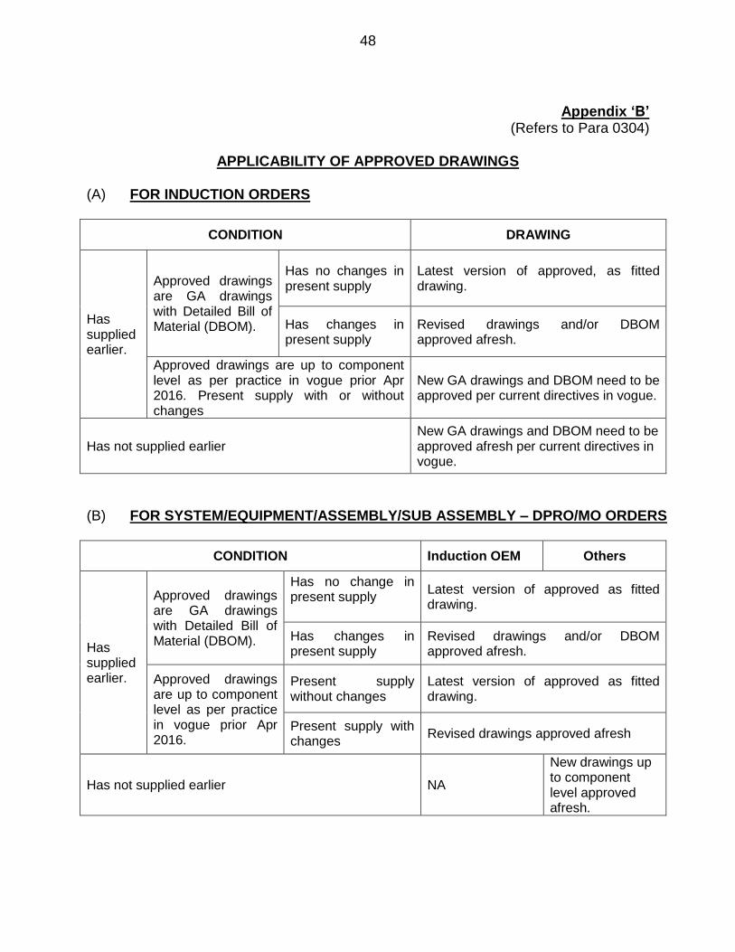
APPLICABILITY OF APPROVED DRAWINGS (A) FOR INDUCTION ORDERS
CONDITION DRAWING
Has supplied earlier.
Approved drawings are GA drawings with Detailed Bill of Material (DBOM).
Has no changes in present supply
Latest version of approved, as fitted drawing.
Has changes in present supply
Revised drawings and/or DBOM approved afresh.
Approved drawings are up to component level as per practice in vogue prior Apr 2016. Present supply with or without changes
New GA drawings and DBOM need to be approved per current directives in vogue.
Has not supplied earlier New GA drawings and DBOM need to be approved afresh per current directives in vogue.
(B) FOR SYSTEM/EQUIPMENT/ASSEMBLY/SUB ASSEMBLY – DPRO/MO ORDERS
CONDITION Induction OEM Others
Has supplied earlier.
Approved drawings are GA drawings with Detailed Bill of Material (DBOM).
Has no change in present supply
Latest version of approved as fitted drawing.
Has changes in present supply
Revised drawings and/or DBOM approved afresh.
Approved drawings are up to component level as per practice in vogue prior Apr 2016.
Present supply without changes
Latest version of approved as fitted drawing.
Present supply with changes
Revised drawings approved afresh
Has not supplied earlier NA
New drawings up to component level approved afresh.

49
(C) FOR SPARES – DPRO / MO ORDERS
CONDITION Inspection
against OEM Tech Specs
Others
Has supplied earlier.
Approved drawings are GA drawings with Detailed Bill of Material (DBOM).
Has no change in present supply
Drawings per DBOM
Has changes in present supply
Revised drawings and/or DBOM approved afresh.
Approved drawings are up to component level as per practice in vogue prior Apr 2016.
Has no change in present supply
Details per Approved PIL
Latest version of approved as fitted drawing.
Has changes in present supply
Revised drawings up to component level, approved afresh.
Has not supplied earlier NA
New drawings up to component level, approved afresh.

50
Appendix ‘C’ (Refers to Para 0304)
SUBMISSION OF DRAWINGS FOR REPLENISHMENT
ORDERS OF EQUIPMENT/SPARES 1. In cases of replenishment orders placed by any OPA, which also includes orders for On Board Spares and Base & Depot Spares for first time inductions, the necessity to have any drawing approved should not arise under normal circumstances, since these have already been inducted into the IN against approved drawings and QAP. 2. Fresh approval of drawings will be required only under following conditions:-
(a) Any change, irrespective of the quantum, in design which includes material, dimensions including tolerances, operating/duty point, binding dimensions etc since these could have effect on stress distributions, compatibility, installation requirements, functional parameters (including endurance and environmental qualification parameters) etc. (b) Any change in manufacturing process or sourcing since these may call for changes in QAP. (c) Any change in governing specifications including reference standards since these may change testing and acceptance norms. (d) In specific cases, where complete equipment system installed in one platform/ship is being retrofitted on another platform/ship which may necessitate changes in the binding data.
3. In cases where there are changes as brought out above, the corresponding drawings needs to be re-approved/re-validated as follows:-
(a) The firm submits the revised drawings along with the original (latest version of drawings approved earlier) to the OPA indicating the changes incorporated/necessitated under intimation to the respective inspecting agency. (b) Where there are no changes in the equipment, but the platform/ship where it would be installed is different from initial fit, the firm to submit the binding data to the respective OPA for ratification, under intimation to the inspecting agency. (c) The OPA obtains approval or otherwise of the competent authority for the changes incorporated/necessitated or the concurrence to use the existing equipment as it is with respect to existing approved drawings on new platform and forwards to inspecting agency for ratification or otherwise of existing QAP.
51
(d) The approval accorded for changes should clearly indicate if its validity is only for the instant order or valid for all future orders as well. Where the changes are valid for all future orders irrespective of command or platform applicability, the necessary amendments to approved drawings is to be endorsed in all records for future procurements. In such cases, this revision of the drawings will become the latest version of approved drawings.
4. In cases where there are no changes and the existing approved drawings are valid, their submission will be governed as follows: -
(a) Where the latest versions of approved drawings are GA drawings along with DBOM, only mention of the relevant item no drawing with traceability to details in PO is sufficient and no physical submission of any drawing is required. The firms will be required to present the original stamped drawing held in its custody to the QA team during the first visit for inspection. (b) Where the latest version of the approved drawings are detailed drawings up to component level, original drawings of the latest version of approved drawings will need to be presented to the QAO for verification. Whilst submission of authenticated copies is sufficient for processing the QAP and other initial formalities, inspection will commence only after verification of the originals. Non-availability of original drawing will require the vendor to obtain fresh approval of the competent authority. (c) In case of spares ordered against OEM Tech Specs, there is no requirement to submit any drawings and inspection will be carried out in accordance with details provided in approved PIL/DBOM.
5. Whenever a change is envisaged or necessitated, the process for revision and/or clarifications can be taken up any time by an OEM with the concerned professional directorate for amendment to their approved drawings and DBOM, even when there is no tender or order pending on the firm. 6. It will be incumbent on all firms responding to a tender, to indicate and intimate any changes that have been incorporated or necessitated in any of the items or components with respect to last approved drawings and supply, during their offer, so that necessary clarifications and approvals can be accorded prior issue of PO, if not done earlier. 7. Any delay or difficulty in execution of order due to changes noticed with respect to last supply that has not been intimated during the offer and before issue of PO will be fully attributable to the firm.

52
Appendix ‘D’ (Refers to Para 0403)
APPLICABILITY OF APPROVED QAPs
(A) FOR INDUCTIONORDERS
CONDITION QAP
SQAP issued
Has supplied earlier
Has no change in present supply
Relevant SQAP as approved for previous order.
Have changes wrt last supply.
Relevant SQAP, with amendments if required
Has not supplied earlier Relevant SQAP, with amendments as required
SQAP not issued
Has supplied earlier.
Has no change in present supply
Latest version of approved QAP. In case a later QAP for similar equipment of a different supplier is available, necessary changes to the existing QAP will be incorporated and issued as ‘Approved as Amended’
Have changes wrt last supply.
Revised QAP if necessary. For faster approval, changes wrt previous supply be submitted along with proposed QAP. Type tests/ Qualification tests will be required unless waived off by OPA
Has not supplied earlier New QAP to be drafted by firm and approved by Inspecting Authority
(B) FOR SYSTEM/EQUIPMENT/ASSEMBLY/SUB ASSEMBLY – DPRO/MO ORDERS
CONDITION Induction OEM Others
SQAP issued
Has supplied earlier.
Has no change in present supply
Relevant SQAP as approved for previous order
Have changes wrt last supply.
Relevant SQAP, with amendments if required
Has not supplied earlier Relevant SQAP, with amendments as required
SQAP not issued
Has supplied earlier.
Has no change in present supply
Latest version of approved QAP
Have changes with respect tolast supply.
May Require Revised QAP. For faster approval, changes with respect toprevious supply be submitted along with proposed QAP. Type tests/ Qualification tests will be required unless waived off by OPA
Has not supplied earlier NA
New QAP to be drafted by firm and approved by Inspecting Authority

53
(C) FOR SPARES – DPRO/MO ORDERS
CONDITION QA per OEM Tech Specs Others
SQAP Issued Details provided in approved DBOM OR PIL
Relevant articles of SQAP
SQAP not issued
Has supplied earlier.
Has no changes with respect tolast supply
Details provided in approved DBOM OR PIL
Latest version of approved QAP
Have changes in present supply
Details in revised and approved DBOM OR PIL
May require amended QAP
Has not supplied earlier NA QAP drafted and approved afresh.

54
Appendix ‘E’ (Refers to Para 0506)
DETAILS OF ACCEPTABLE IMPORT DOCUMENTS
Sl No
Document Interpretation Acceptable Documents Remarks
1
Bill of Lading
Bill of lading is a document issued by the carrier which details a shipment of merchandise and gives title of that shipment to a specified party OR Bill of Lading is a document issued by the actual transporter (Ship, Airway or agent) of the equipment which clearly indicate the description, quantity,port of collection and port of discharge
(a) Bill or receipt issued by the Shipping Company/Shipping agent/ Ships’ Captain
(b) Shipping Bill (c) Airway bill (d) Couriers’ Bill
In case main firm intends procuring the imported component/item though other Indian sources through suborder, the same should be ratified by OPA, preferably before placement of PO. In such cases, the original importers’ document can be accepted if traceability can be established with respect to the items being supplied as having been currently and correctly imported. If Indian vendor receive items through Courier services and are unable to submit the original Bill of Lading, items can be cleared based on packing slip on the consignment and verifying Courier service's Bar Code on packing.
2
Shipping Bill
Shipping Bill is a form used by Customs & Excise before goods can be exported from the country or removed from a bonded warehouse and indicates details of PO, goods, consignee etc.
(a) Invoice issued by foreign firm giving details of PO, goods, consignee etc and submitted to freight agent/customs towards transportation by sea/air (b) Complete packing list of all items along with complete details of ship/flight through which the item have been supplied, issued by logistic firm tasked by foreign supplier/ manufacturer to supply the item
It is an imp document required by Customs authorities for allowing shipment. It is prepared by exporter & it contains following :-
1. Name of Vessel 2. Name of the port of discharge 3. Country of final destination 4. Exporter's name and address 5. Details about packages. 6. Quantity and details of each case 7. FOB price 8.Total no. of packages with weight & value 9. Name and address of the importer

55
3
Bill of Entry to Ware Housing
A form issued by Indian Customs and Excise to list goods prior to entry to warehouse for home consumption on import
Certificate by Indian Customs giving confirmation of the entry of items into the Indian port containing the details of supplier, port of loading , country of origin, no of packages and weight etc.
4
Country of Origin
A document which certifies that the products exported are wholly obtained/produced or manufactured in that particular Country. This certificate is issued by the Chambers of Commerce/ Such Authorised Signatory of the country in which imported item /equipment is manufactured.
(a) Country of Origin certificate issued by Chamber of Commerce or Government of respective country. (b) If country of origin is indicated in Shipping Bill or Bill for entry to warehousing and is matching with BOM, the same may be accepted.
(c) In case firm cannot produce country of origin certificate issued by Chamber of Commerce or Government of respective country, the same should be told upfront to OPA and if OPA ratifies in Purchase Order or subsequent document, one of the following documents can be accepted
(i) Certificate issued by Foreign Supplier/OEM
(ii) Declaration Certificate for country of origin issued by the OEM in case of PAC firms
Country of Origin (COO) is the country of manufacture, production or growth where an article or product comes from. The origin of the product does not refer to the country where the goods were shipped from but to the country where they were made. In the event of the product being manufactured in two or more countries, origin is obtained in the country where the last substantial economically justified working or processing is carried out. As a thumb rule if more than 50% of the cost of producing the goods originates from one country, then that country is acceptable as the country of origin. In case of trading bloc, certificate of origin may be allowed to state the trading bloc (for e.g. European Union as origin) rather than specific country
5
OEM'S Certificate of Conformance
Certificate of Conformance (CoC) issued by OEM stating that spares are tested for FORM,FUNCTION& FITMENT OR
CoC issued by the OEM from whom the item/equipment is sourced.
CoC is to be verified against specific serial no or batch no, to be available on the CoC and same details of the instant piece/pieces being supplied.
56
A document certified by a competent authority committing or promising that the supplied good or service it covers meets the agreed upon or required specifications.
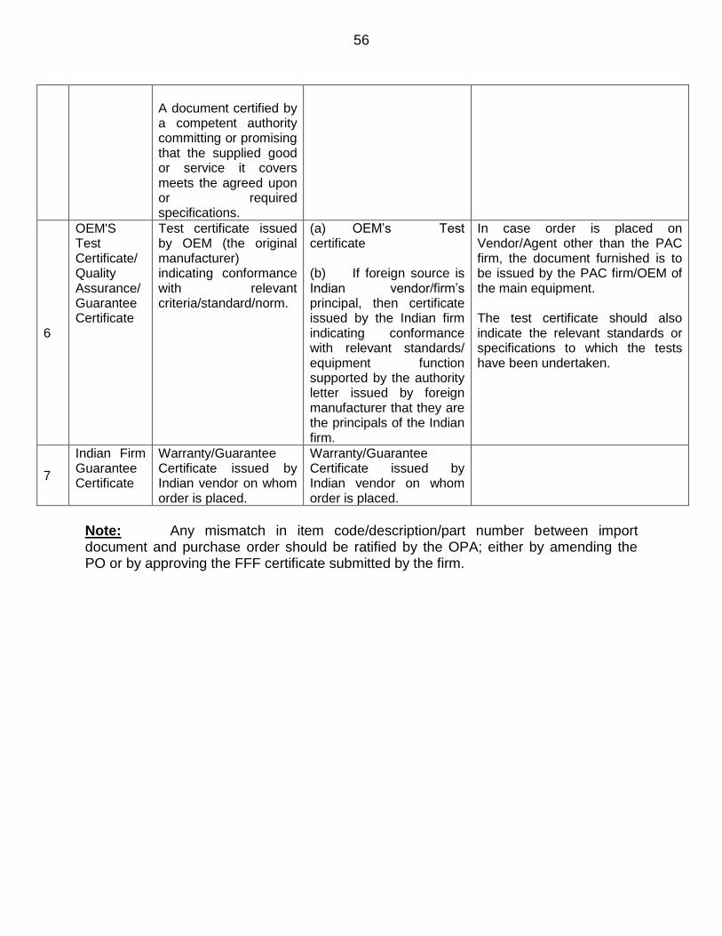
6
OEM'S Test Certificate/ Quality Assurance/ Guarantee Certificate
Test certificate issued by OEM (the original manufacturer) indicating conformance with relevant criteria/standard/norm.
(a) OEM’s Test certificate (b) If foreign source is Indian vendor/firm’s principal, then certificate issued by the Indian firm indicating conformance with relevant standards/ equipment function supported by the authority letter issued by foreign manufacturer that they are the principals of the Indian firm.
In case order is placed on Vendor/Agent other than the PAC firm, the document furnished is to be issued by the PAC firm/OEM of the main equipment. The test certificate should also indicate the relevant standards or specifications to which the tests have been undertaken.
7
Indian Firm Guarantee Certificate
Warranty/Guarantee Certificate issued by Indian vendor on whom order is placed.
Warranty/Guarantee Certificate issued by Indian vendor on whom order is placed.
Note: Any mismatch in item code/description/part number between import document and purchase order should be ratified by the OPA; either by amending the PO or by approving the FFF certificate submitted by the firm.
57

58
Appendix ‘F’ (Refers to Para 0603(a))
GUIDELINES FOR CONDUCT OF ESS
Aim 1. The aim of this letter is to lay down guidelines for formulation of effective ESS programme and methodology for conduct of ESS on Electronic Components/Units/ PCBs/Modules. The guidelines also provide directions to manufacturing agencies to incorporate tests at the design and manufacturing stage to weed out such deficiencies, which can manifest at a later stage causing avoidable down time of the equipment and expensive corrective action thereupon. Applicability of ESS 2. Indigenous Manufacturing. The ESS is to be applied to 100% electronic components/units/assemblies as part of manufacturing process for indigenously manufactured electronics. Hardware incorporating purely mechanical system/elements including wire wrapped backplanes and fragile electronic items viz. LCD panels, Hard Disk Drives etc may be exempted from ESS.
3. The present guidelines will be applicable for the new POs placed after promulgation of this policy. For all previous POs, ESS plan as per approved QAP may be followed. For new orders pertaining to spares of Systems/Equipment supplied earlier, ESS scheme as per guidelines in vogue/as conducted at the time of delivery of the system would be applicable. 4. Applicability for Imported/COTS Items. In case of imported and COTS items, following guidelines will apply:-
(a) During the course of production, a variety of imported/COTS items (components/PCBs/modules) may be used by the manufacturer of main system. ESS on such items is to be carried out at the next higher indenture level. The severities are to be decided based on designed parameter of weakest component as per data sheets of components in order to ensure that there is no damage to the used part whilst conduct of ESS.
(b) However, in case the Imported items are being supplied by the manufacturer in ‘As It Is’ condition with no addition/alternations, such items are to be accepted based on CoCs clearly endorsing the standards to which the items comply and physical values of test conditions the items have been subjected to ESS. (c) Use of fully finished COTS items needs to be specifically approved by IHQ MoD(N)/(Professional Dates)/OPA and are to be accepted against CoCs as in case of ‘As It Is’ imported items.

59
ESS Programme 5. It is necessary to conduct ESS at the earliest possible stages where it is possible to reveal latent defects and initiate necessary corrective actions. Following needs consideration while devising effective ESS programme:-
(a) A viable ESS program must be dynamic wherein the screen parameters must be actively managed and tailored to the particular characteristics of the equipment being screened. (b) Effective ESS program generally involve more than one type of screen. (c) Thermal cycling and random vibration are considered the first and second most effective screens respectively in identifying latent defects.
(d) While severity of the applied stress screen must be strong enough to effectively reveal the latent defects, care must also be taken not to over-stress the item which could either cause damage or reduction in residual life. At the same time, non-precipitation of latent defects is indication of weak stress level. The stress must conform to stringent level within designed parameters of the weakest component. Design parameters are generally much higher than the operating parameters.
(e) ESS is applied to 100% of the units manufactured including spares and repaired units.
ESS Process Sequence 6. The electronic hardware is recommended to be screened as per the following sequence:-
Stage-1 : Perform thermal cycling screening at PCB level Stage-2 : Perform random vibration at PCB level or higher indenture Stage-3 : Repeat thermal cycling screening at an indenture higher than
PCB level 7. The conduct of thermal cycling prior to random vibration pre-stresses potential defects which can then be surfaced more effectively by random vibration. Random vibration also conditions some defects to the point of failure which are detected by a subsequent thermal cycling with performance monitoring. All ESS requirements must be accomplished at the lowest feasible level of assembly. The following three indenture

60
levels have been identified for conduct of ESS: -
(a) PCB level (b) Module/ sub-unit level
(c) Unit/Cabinet level
ESS Flow Diagram
Stage 1 Stage 2 Stage 3
Stage -1 Stage -2 Stage -3
8. Screens for Conduct of ESS. A tailored screen requires that specific parameters of equipment being screened, be reviewed such that defects are detected and removed without incurring undue damage to the equipment. The screening levels should not exceed design limits, but they must be of sufficient strength to precipitate failures due to weak parts and manufacturing defects at the earliest time such that corrections are most cost effective. Two screens each for Thermal Cycling Stress Screening (TCSS) and Random Vibration Stress Screening (RVSS) have been defined at Annexure III&IV respectively. In case a screen with severity below the above two screens is proposed for any item, approval of Professional Directorate is to be sought for use of such items with suitable justification. The screen for such cases would then be worked out based on the limitations imposed by the specifications of the items approved to be used. Accordingly, the applicable screen severities can be categorized as follows: -
(a) Screen-A (Severe). This would be the default screen with most stringent severity based on design parameters of weakest component for effective precipitation of latent defect. (b) Screen-B (Moderate). To be selected based on parameters of the items necessitating use of screen severity below the above Screen ‘A’ category. Prior approval for use of such items has to be obtained by the firm from Professional Directorate. The tailored screen would accordingly be specified in the QAP with suitable justifications. Reason for application of this screen for the item instead of Screen ‘A’ is to be justified in the QAP and list to be attached with QAP.
9. Based on the above process sequence and categorisation of screens, it is proposed to denote the stress severity of products as per the notation “Product (XXX)”, where the first “X” represents thermal screen severity for Stage-1,
PCB - Thermal
Cycling Stress
Screening
PCB or Higher
Indenture Level -
Random Vibration
Stress Screening
Higher Indenture Level
otherthan PCB - Thermal
Cycling Stress Screening

61
the second “X” represents screen severity for random vibration at Stage-2 and third “X” represents thermal screen severity for Stage-3. For example “Item (ABB)” would indicate that the item is to be subjected to thermal stress as per screen ‘A’ in Stage-1, random vibration as per screen B in Stage-2 and thermal stress as per screen B in Stage-3. A proposed format for ESS plan is placed at Annexure V.
10. Thermal Cycling Stress Screening (TCSS). The following aspects are to be considered whilst conducting TCSS:-
(a) The temperature range for thermal cycling should be established by considering the component characteristics and the equipment specifications for maximum and minimum designed values under operating and storage conditions. The temperature range should be as large as component characteristics will permit regardless of the products intended operational limits. (b) The rate of change of temperature between the extremes must be as rapid as possible to create the optimum level of thermal stress. The minimum acceptable rate of change is 5° C per minute.
(c) The number of cycles is more closely related to the temperature range and rate of change than to the equipment complexity or number of parts. Tailoring of this parameter is generally done based on the analysis of failures observed with the incremental number of cycles. (d) Dwell time at maximum and minimum operating and storage temperatures should be only enough to achieve thermal stability.
11. Random Vibration Stress Screening (RVSS). The following aspects are to be considered whilst conducting RVSS:-
(a) Random Vibration Stress Screening may be performed preferably at lower indenture level.
(b) The attitude or orientation of item for RVSS shall be decided based on the plane which provides maximum shear force to the soldered joints and components during random vibration. The RVSS is to be conducted preferably in allthree axes. (c) For a module level testing, the fixture shall be structurally rigid without causing resonance and further amplification to the Unit Under Test (UUT). (d) EUT shall be subjected to sinusoidal sweep between 20-2000 Hz to identify the existence resonance prior to conduct of RVSS. If the equipment resonance frequencies fall within the input frequency range, excessive energy could be seen by the equipment and damage could occur. One of the following two measures may be taken in such cases: -

62
(i) Modify the equipment design to achieve a more rugged item to obtain a resonance falling outside the input frequency range. (ii) Make a notch on the input profile eliminating frequency band of 5 Hz before and after the resonating frequency.
12. Approval of ESS Programme. The manufacturer is solely responsible for drawing up the ESS programme as the design parameters of the components are known to them. Once the ESS screen is finalized, the same is to be submitted to DQA(N) through respective field units for approval. Such ESS plan will be annexed to the QAP.

63
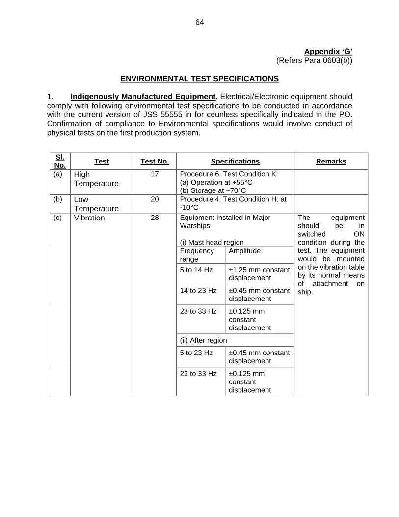
64
Appendix ‘G’ (Refers Para 0603(b))
ENVIRONMENTAL TEST SPECIFICATIONS
1. Indigenously Manufactured Equipment. Electrical/Electronic equipment should comply with following environmental test specifications to be conducted in accordance with the current version of JSS 55555 in for ceunless specifically indicated in the PO. Confirmation of compliance to Environmental specifications would involve conduct of physical tests on the first production system.
Sl. No.
Test Test No. Specifications Remarks
(a) High Temperature
17 Procedure 6. Test Condition K: (a) Operation at +55°C (b) Storage at +70°C
(b) Low Temperature
20 Procedure 4. Test Condition H: at -10°C
(c) Vibration 28 Equipment Installed in Major Warships (i) Mast head region
The equipment should be in switched ON condition during the test. The equipment would be mounted on the vibration table by its normal means of attachment on ship.
Frequency range
Amplitude
5 to 14 Hz ±1.25 mm constant displacement
14 to 23 Hz ±0.45 mm constant displacement
23 to 33 Hz ±0.125 mm constant displacement
(ii) After region
5 to 23 Hz
±0.45 mm constant displacement
23 to 33 Hz ±0.125 mm constant displacement

65
(iii) Main region
5 to 33 Hz
±0.125 mm constant displacement
(d) Mould Growth
21 Temperature 30°C, RH greater than 90%
Separate equipment can be used for this test. To be conducted on representative samples.
(e) Corrosion Salt 9 Temp 350 C and RH 90 to 95 % For Exposed items - Procedure 1 For Protected items-Procedure 2
Separate equipment can be used for this test. To be conducted on representative samples.
(f) Driving Rain 12 Test Condition C For exposed items
(g) Damp Heat 10 The temperature and relative humidity 40°C at 95% RH
(h) Tropical Exposure
27 Test condition A – 7 cycles (Protected) Test condition C – 28 cycles (Exposed)
(j) Drip Proof 11 - For protected items
(k) Solar Radiation 25 Irradiance of 1.2 + 0.10 kW/m2
Procedure 1 For exposed items
(l) Shock or Impact
24 (a) NSS Grade I (for equipment fitted below waterline) – 120g, 8ms (vertical) and 70g, 8ms (lateral). (b) NSS Grade II (for equipment fitted above waterline) – 50g, 11ms (vertical) and 22g, 8ms (lateral).
The equipment should be in switched OFF condition during the test.
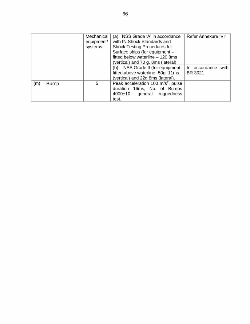
66
Mechanical equipment/ systems
(a) NSS Grade ‘A’ in accordance with IN Shock Standards and Shock Testing Procedures for Surface ships (for equipment – fitted below waterline – 120 8ms (vertical) and 70 g, 8ms (lateral)
Refer Annexure ‘VI‘
(b) NSS Grade II (for equipment fitted above waterline -50g, 11ms (vertical) and 22g 8ms (lateral).
In accordance with BR 3021
(m) Bump 5 Peak acceleration 100 m/s2, pulse duration 16ms, No. of Bumps 4000±10, general ruggedness test.

67
68
Appendix ‘H’
(Refers Para 0604(c))
FACTORY ACCEPTANCE TRIALS
1. FATs, if indicated as part of the PO, are the ultimate test to validate the design and performance of the equipment before it leaves the supplier’s premises for installation on board. It is therefore mandatory that all pre-requisites towards conduct of FATs are completed and available to the satisfaction of the FATs team. 2. The pre-requisites and procedures for conduct of FATs are enumerated in succeeding paragraphs. 3. Pre-requisites. Availability of the following are essential pre-requisites for conduct of FATs:-
(a) FATs protocol approved by the professional directorate. The approval should also include interface protocols signed between WESEE and the firm. (b) Approved system layout, including technological components if any. The requirement or otherwise to provide simulators to cater for interfacing system/equipment require to prove FATs protocol but not available with the firm should be clearly mentioned in the approved layout.
(c) Operating and limiting parameters to be monitored, including essential and/or permissible physical phenomenon like leakages, hunting, deflections etc. (d) Report of FATs undertaken in-house. (e) Draft operating manual of the system/equipment. (f) Any other equipment/system specific requirement as provided in the PO. (g) FATs team as constituted by IHQ/ Professional Directorates/ OPA. (h) Completion of all QA activities preceding FATs.
4. Conduct. On the availability or assured availability of the pre-requisites at sub paras 3(a) to 3(h) above, the firm is to make a formal request to IHQ MoD(N)/OPA, under intimation to the Inspecting Authority and Inspection Agency for scheduling FATs. On receipt of the request, the competent authority for FATs will co-ordinate and schedule the conduct of FATs per extant procedures in force.

69
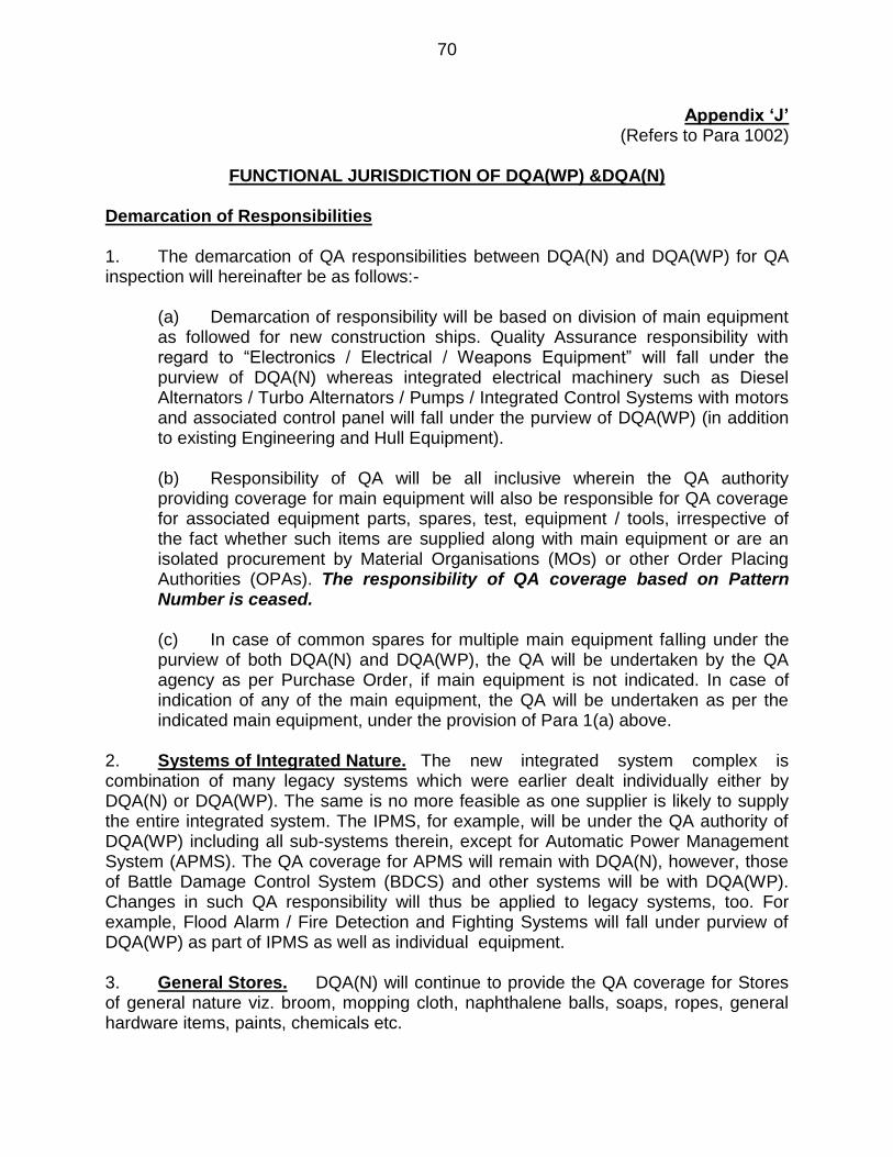
70
Appendix ‘J’ (Refers to Para 1002)
FUNCTIONAL JURISDICTION OF DQA(WP) &DQA(N)
Demarcation of Responsibilities
1. The demarcation of QA responsibilities between DQA(N) and DQA(WP) for QA inspection will hereinafter be as follows:-
(a) Demarcation of responsibility will be based on division of main equipment as followed for new construction ships. Quality Assurance responsibility with regard to “Electronics / Electrical / Weapons Equipment” will fall under the purview of DQA(N) whereas integrated electrical machinery such as Diesel Alternators / Turbo Alternators / Pumps / Integrated Control Systems with motors and associated control panel will fall under the purview of DQA(WP) (in addition to existing Engineering and Hull Equipment). (b) Responsibility of QA will be all inclusive wherein the QA authority providing coverage for main equipment will also be responsible for QA coverage for associated equipment parts, spares, test, equipment / tools, irrespective of the fact whether such items are supplied along with main equipment or are an isolated procurement by Material Organisations (MOs) or other Order Placing Authorities (OPAs). The responsibility of QA coverage based on Pattern Number is ceased.
(c) In case of common spares for multiple main equipment falling under the purview of both DQA(N) and DQA(WP), the QA will be undertaken by the QA agency as per Purchase Order, if main equipment is not indicated. In case of indication of any of the main equipment, the QA will be undertaken as per the indicated main equipment, under the provision of Para 1(a) above.
2. Systems of Integrated Nature. The new integrated system complex is combination of many legacy systems which were earlier dealt individually either by DQA(N) or DQA(WP). The same is no more feasible as one supplier is likely to supply the entire integrated system. The IPMS, for example, will be under the QA authority of DQA(WP) including all sub-systems therein, except for Automatic Power Management System (APMS). The QA coverage for APMS will remain with DQA(N), however, those of Battle Damage Control System (BDCS) and other systems will be with DQA(WP). Changes in such QA responsibility will thus be applied to legacy systems, too. For example, Flood Alarm / Fire Detection and Fighting Systems will fall under purview of DQA(WP) as part of IPMS as well as individual equipment. 3. General Stores. DQA(N) will continue to provide the QA coverage for Stores of general nature viz. broom, mopping cloth, naphthalene balls, soaps, ropes, general hardware items, paints, chemicals etc.
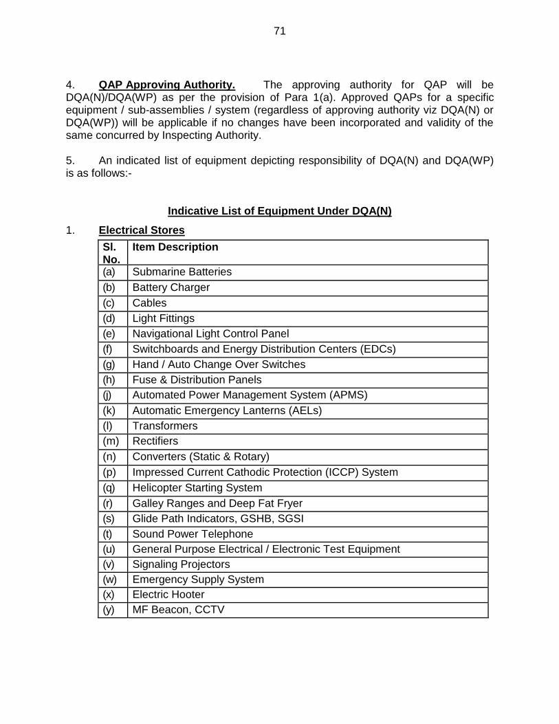
71
4. QAP Approving Authority. The approving authority for QAP will be DQA(N)/DQA(WP) as per the provision of Para 1(a). Approved QAPs for a specific equipment / sub-assemblies / system (regardless of approving authority viz DQA(N) or DQA(WP)) will be applicable if no changes have been incorporated and validity of the same concurred by Inspecting Authority. 5. An indicated list of equipment depicting responsibility of DQA(N) and DQA(WP) is as follows:-
Indicative List of Equipment Under DQA(N)
1. Electrical Stores
Sl. No.
Item Description
(a) Submarine Batteries
(b) Battery Charger
(c) Cables
(d) Light Fittings
(e) Navigational Light Control Panel
(f) Switchboards and Energy Distribution Centers (EDCs)
(g) Hand / Auto Change Over Switches
(h) Fuse & Distribution Panels
(j) Automated Power Management System (APMS)
(a) (k) Automatic Emergency Lanterns (AELs)
(b) (l) Transformers
(c) (m) Rectifiers
(d) (n) Converters (Static & Rotary)
(e) (p) Impressed Current Cathodic Protection (ICCP) System
(q) Helicopter Starting System
(r) Galley Ranges and Deep Fat Fryer
(s) Glide Path Indicators, GSHB, SGSI
(t) Sound Power Telephone
(u) General Purpose Electrical / Electronic Test Equipment
(v) Signaling Projectors
(w) Emergency Supply System
(x) Electric Hooter
(y) MF Beacon, CCTV
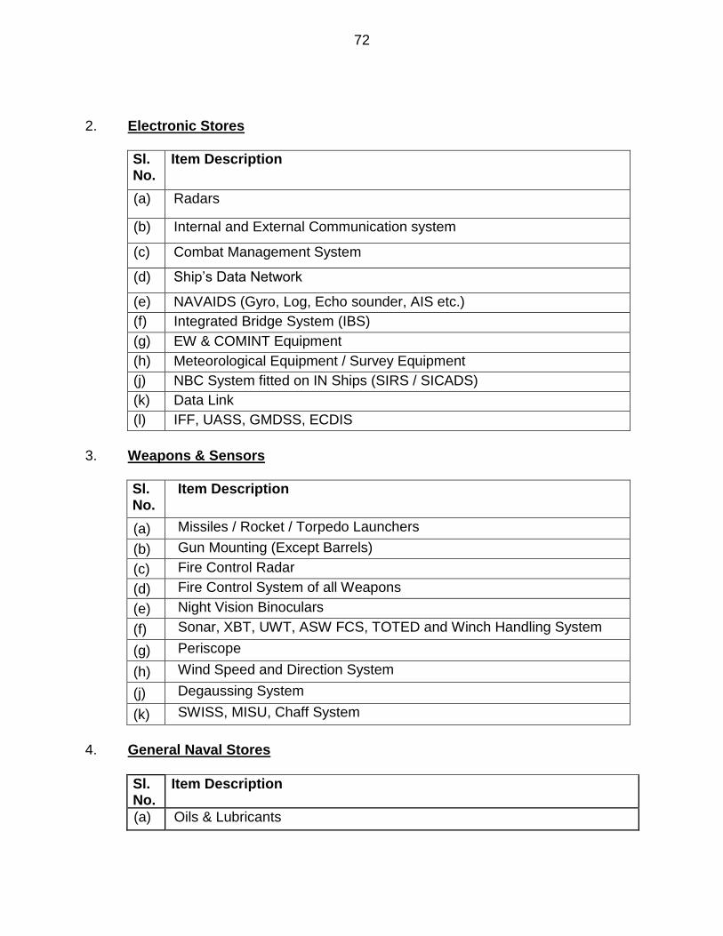
72
2. Electronic Stores
Sl. No.
Item Description
(a) Radars
(b) Internal and External Communication system
(c) Combat Management System
(d) Ship’s Data Network
(e) NAVAIDS (Gyro, Log, Echo sounder, AIS etc.)
(f) Integrated Bridge System (IBS)
(g) EW & COMINT Equipment
(h) Meteorological Equipment / Survey Equipment
(j) NBC System fitted on IN Ships (SIRS / SICADS)
(k) Data Link
(l) IFF, UASS, GMDSS, ECDIS
3. Weapons & Sensors
Sl. No.
Item Description
(a) Missiles / Rocket / Torpedo Launchers
(b) Gun Mounting (Except Barrels)
(c) Fire Control Radar
(d) Fire Control System of all Weapons
(e) Night Vision Binoculars
(f) Sonar, XBT, UWT, ASW FCS, TOTED and Winch Handling System
(g) Periscope
(h) Wind Speed and Direction System
(j) Degaussing System
(k) SWISS, MISU, Chaff System
4. General Naval Stores
Sl. No.
Item Description
(a) Oils & Lubricants
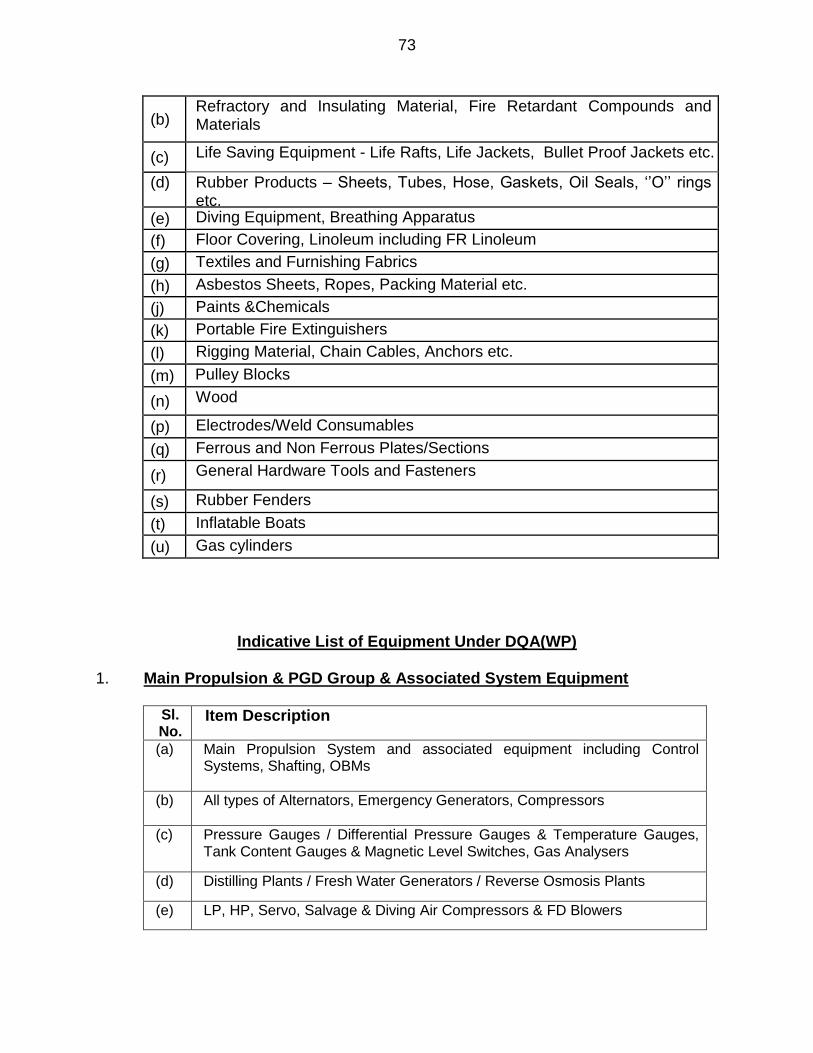
73
(b) Refractory and Insulating Material, Fire Retardant Compounds and Materials (c) Life Saving Equipment - Life Rafts, Life Jackets, Bullet Proof Jackets etc.
(d) Rubber Products – Sheets, Tubes, Hose, Gaskets, Oil Seals, ‘’O’’ rings etc.
(e) Diving Equipment, Breathing Apparatus
(f) Floor Covering, Linoleum including FR Linoleum
(g) Textiles and Furnishing Fabrics
(h) Asbestos Sheets, Ropes, Packing Material etc.
(j) Paints &Chemicals
(k) Portable Fire Extinguishers
(l) Rigging Material, Chain Cables, Anchors etc.
(m) Pulley Blocks
(n) Wood
(p) Electrodes/Weld Consumables
(q) Ferrous and Non Ferrous Plates/Sections
(r) General Hardware Tools and Fasteners
(s) Rubber Fenders
(t) Inflatable Boats
(u) Gas cylinders
Indicative List of Equipment Under DQA(WP)
1. Main Propulsion & PGD Group & Associated System Equipment
Sl. No.
Item Description
(a) Main Propulsion System and associated equipment including Control Systems, Shafting, OBMs
(b) All types of Alternators, Emergency Generators, Compressors
(c) Pressure Gauges / Differential Pressure Gauges & Temperature Gauges, Tank Content Gauges & Magnetic Level Switches, Gas Analysers
(d) Distilling Plants / Fresh Water Generators / Reverse Osmosis Plants
(e) LP, HP, Servo, Salvage & Diving Air Compressors & FD Blowers

74
(f) Valves for Steam Systems Fuel / Lub Oil System, Compressed Air System, Avcat System, Fire Main, Sea Water, Fresh Water and Chilled Water System including underwater valves, Rod Gearing for Valves
(g) IPMS
2. Auxiliary Equipment
Sl. No.
Item Description
(a) All types of pumps (Motor Driven as well as Diesel Driven) with associated motors and Control / Starter Panels
(b) A/C, Refrigeration and Ventilation system (other than trunking) including associated equipment and control panels
(c) System Pipes. All types of Steam Systems, Fuel / Lube Oil and Lubrication System, Compressed Air System, Tele motor System, Hydraulic System, Avcat System, Fresh Water / Chilled Water System, Sea Water / Brine System, Ref Gas system, Exhaust System of all types of equipment including compensators, Boiler Tubes
(d) Steering Gear and associated equipment including Control Panel
(e) Ship’s Stabilizer and associated equipment including control panel and auto pilot
(f) Bilge Separators & Bilge Eductors / Ejectors, Steam Sirens, Air Whistle
(g) Shock Mounts
3. Hull, Miscellaneous & Fire Fighting Equipment
Sl. No.
Item Description
(a) Fire and Flood Alarm System including associated valves, Sensors and Control Panels, Fixed Fire Fighting systems
(b) All types of Doors & Hatches, Man Holes, Bow Door & Ramps, Scuttles / Windows, Deck Head Tubes / Glands, Ladders,
(c) Helo Traversing & Handling system, Helo Landing Grid, Helo Hangar & general purpose Rolling shutters, Helo Fuelling / De-fuelling System.
(d) LP / HP Air Bottles
(e) Davits, Derricks, Booms, Fairleads, Bollards, Capstan, Winches for Helicopter Handling / Towing / Minesweeping Boat Davit / Ammunition Loading & General Purpose.
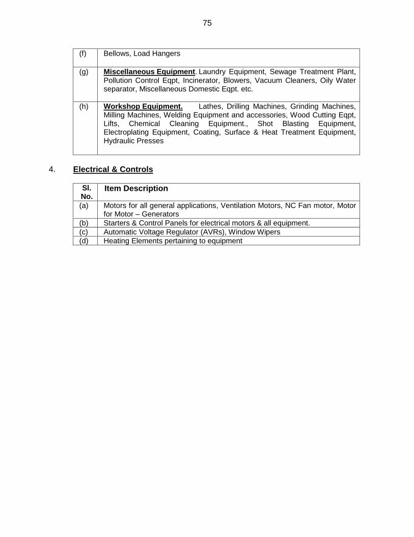
75
(f) Bellows, Load Hangers
(g) Miscellaneous Equipment. Laundry Equipment, Sewage Treatment Plant, Pollution Control Eqpt, Incinerator, Blowers, Vacuum Cleaners, Oily Water separator, Miscellaneous Domestic Eqpt. etc.
(h) Workshop Equipment. Lathes, Drilling Machines, Grinding Machines, Milling Machines, Welding Equipment and accessories, Wood Cutting Eqpt, Lifts, Chemical Cleaning Equipment., Shot Blasting Equipment, Electroplating Equipment, Coating, Surface & Heat Treatment Equipment, Hydraulic Presses
4. Electrical & Controls
Sl. No.
Item Description
(a) Motors for all general applications, Ventilation Motors, NC Fan motor, Motor for Motor – Generators
(b) Starters & Control Panels for electrical motors & all equipment.
(c) Automatic Voltage Regulator (AVRs), Window Wipers
(d) Heating Elements pertaining to equipment
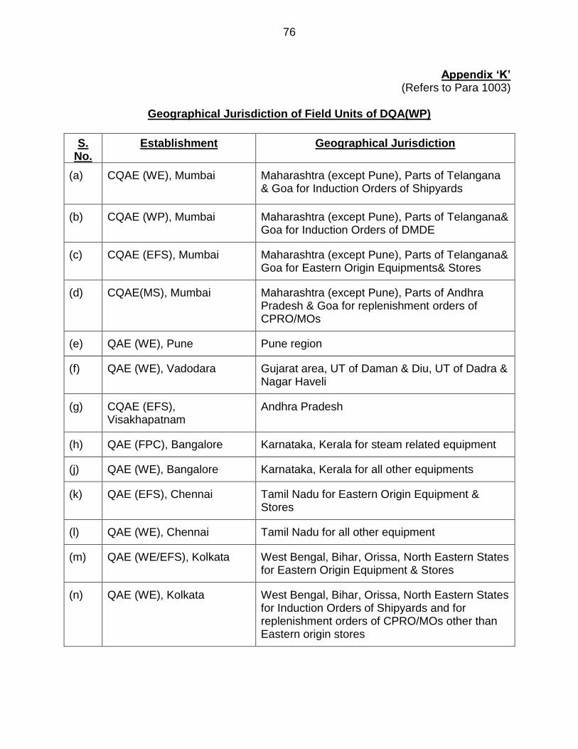
76
Appendix ‘K’ (Refers to Para 1003)
Geographical Jurisdiction of Field Units of DQA(WP)
S. No.
Establishment Geographical Jurisdiction
(a) CQAE (WE), Mumbai Maharashtra (except Pune), Parts of Telangana & Goa for Induction Orders of Shipyards
(b) CQAE (WP), Mumbai Maharashtra (except Pune), Parts of Telangana& Goa for Induction Orders of DMDE
(c) CQAE (EFS), Mumbai Maharashtra (except Pune), Parts of Telangana& Goa for Eastern Origin Equipments& Stores
(d) CQAE(MS), Mumbai Maharashtra (except Pune), Parts of Andhra Pradesh & Goa for replenishment orders of CPRO/MOs
(e) QAE (WE), Pune Pune region
(f) QAE (WE), Vadodara Gujarat area, UT of Daman & Diu, UT of Dadra & Nagar Haveli
(g) CQAE (EFS), Visakhapatnam
Andhra Pradesh
(h) QAE (FPC), Bangalore Karnataka, Kerala for steam related equipment
(j) QAE (WE), Bangalore Karnataka, Kerala for all other equipments
(k) QAE (EFS), Chennai Tamil Nadu for Eastern Origin Equipment & Stores
(l) QAE (WE), Chennai Tamil Nadu for all other equipment
(m) QAE (WE/EFS), Kolkata West Bengal, Bihar, Orissa, North Eastern States for Eastern Origin Equipment & Stores
(n) QAE (WE), Kolkata West Bengal, Bihar, Orissa, North Eastern States for Induction Orders of Shipyards and for replenishment orders of CPRO/MOs other than Eastern origin stores
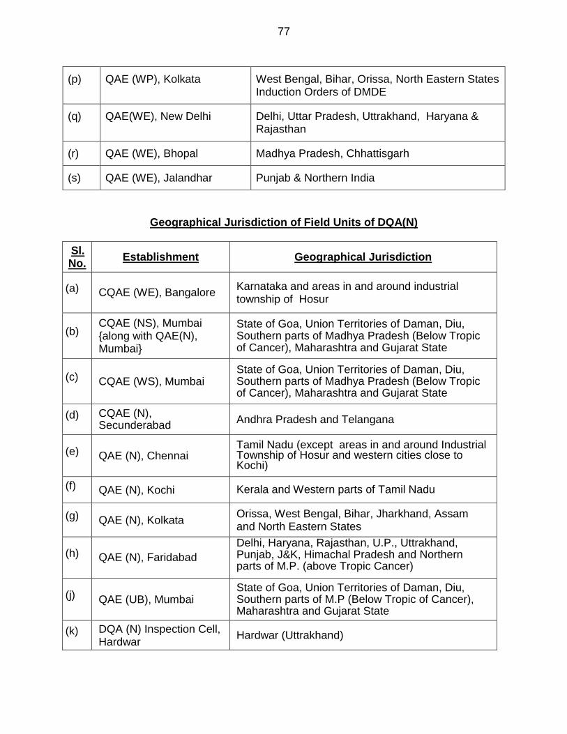
77
(p) QAE (WP), Kolkata West Bengal, Bihar, Orissa, North Eastern States Induction Orders of DMDE
(q) QAE(WE), New Delhi Delhi, Uttar Pradesh, Uttrakhand, Haryana & Rajasthan
(r) QAE (WE), Bhopal Madhya Pradesh, Chhattisgarh
(s) QAE (WE), Jalandhar Punjab & Northern India
Geographical Jurisdiction of Field Units of DQA(N)
Sl. No.
Establishment Geographical Jurisdiction
(a) CQAE (WE), Bangalore Karnataka and areas in and around industrial township of Hosur
(b) CQAE (NS), Mumbai {along with QAE(N), Mumbai}
State of Goa, Union Territories of Daman, Diu, Southern parts of Madhya Pradesh (Below Tropic of Cancer), Maharashtra and Gujarat State
(c) CQAE (WS), Mumbai State of Goa, Union Territories of Daman, Diu, Southern parts of Madhya Pradesh (Below Tropic of Cancer), Maharashtra and Gujarat State
(d) CQAE (N), Secunderabad
Andhra Pradesh and Telangana
(e) QAE (N), Chennai Tamil Nadu (except areas in and around Industrial Township of Hosur and western cities close to Kochi)
(f) QAE (N), Kochi Kerala and Western parts of Tamil Nadu
(g) QAE (N), Kolkata Orissa, West Bengal, Bihar, Jharkhand, Assam and North Eastern States
(h) QAE (N), Faridabad
Delhi, Haryana, Rajasthan, U.P., Uttrakhand, Punjab, J&K, Himachal Pradesh and Northern parts of M.P. (above Tropic Cancer)
(j) QAE (UB), Mumbai
State of Goa, Union Territories of Daman, Diu, Southern parts of M.P (Below Tropic of Cancer), Maharashtra and Gujarat State
(k) DQA (N) Inspection Cell, Hardwar
Hardwar (Uttrakhand)
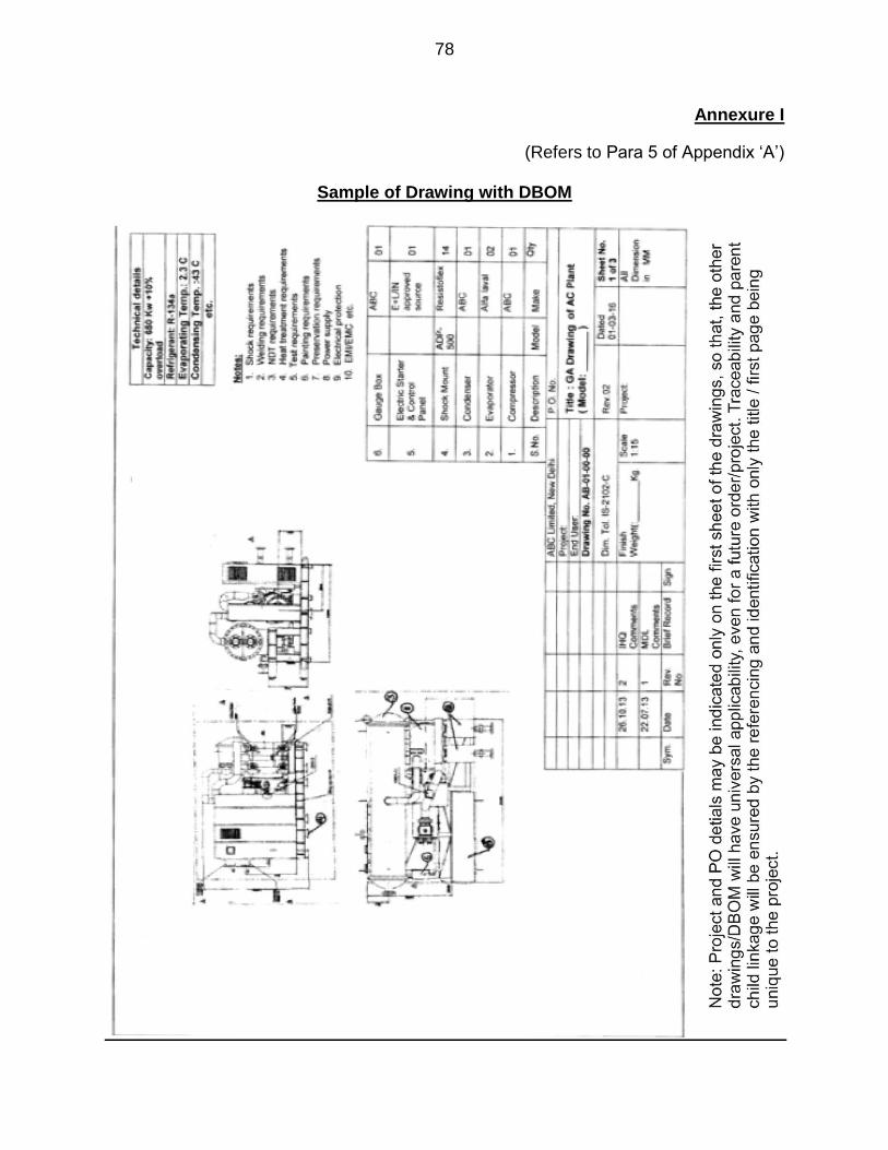
78
Annexure I
(Refers to Para 5 of Appendix ‘A’)
Sample of Drawing with DBOM

79

80

81

82
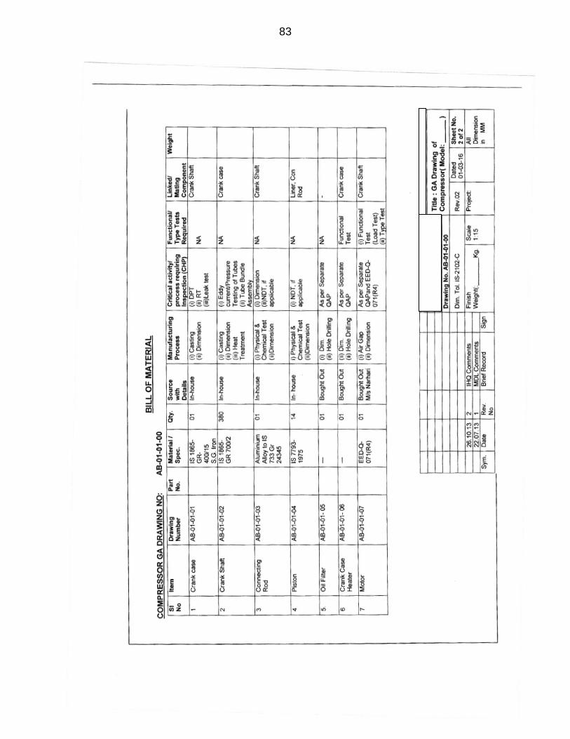
83
84
Annexure II
(Refers to Para 5 of Appendix ‘A’)
Guidelines for Preparation of GA Drawings 1. The drawings are to conform to basic design of engineering drawing as per BIS-SP 46-2003. 2. Besides meeting the basic requirements as per BIS-SP 46-2003, the following specific details are to be provided with the drawings:-
(a) The title Block of drawing should have additional details as follows:- (i) Description of Equipment/component with Model
(ii) Part No. of the component
(iii) Drawing revision no
(b) Technical Details Block to be provided with design data /Operating parameters. (c) Requirements to meet Purchase order and specifications, especially requiring approval from designer; is to be included under heading "Notes". The following details, where applicable, to be included under "Notes" heading:-
(i) Shock requirements (ii) Welding requirements (iii) NDT requirements (iv) Heat treatment requirements (v) Specific test viz functional check, Pressure/leak test etc. (vi) Painting requirements (vii) Preservation requirements (viii) Surface Treatment (ix) Electrical Protection (x) EMI/EMC requirements (xi) Type testing requirements (xii) Weight & CG details (xiii) Tolerances & Surface finish details
(d) The drawings should have one broad "Bill of Material" on the drawing indicating all major assemblies/sub-assemblies/components as per BIS-SP 46 -2003.
85
(e) In addition, an additional sheet called "Detailed Bill of Material (DBOM)" having details of the assemblies, sub-assemblies and components in the drawings. The details to be provided is as per para 4 of the procedure and in conformity with the sample case presented. (f) Drawings of all assemblies, sub-assemblies and components of the system should have forward and backward traceability. The methodology of traceability adopted should therefore be appended to the set of GA drawings submitted, to ensure that all users can exploit the details provided in the drawings. A suggested numbering system is given below:- AB -000-000- 000-000
Two alphabets of Firm's name Numerical Indication of System Numerical indication of Equipment/ Assembly Numerical indication sub- assembly Numerical indication of Component
For example: Order is placed on M/s ABC Ltd. to supply AC Plant
The first two alphabets may be AB First three numeric will be 001-006 for 20 – 140 (7 models
available) TR AC plant assembly Second three numeric will be 001-006 for sub-assemblies viz.
Compressor, Condenser, Evaporator, receiver, Oil tank Separator and Base frame etc.
Third three numeric will be 001-999 for components of sub –
sub assemblies like tube bundle with tube sheet, oil pump in compressor, pressure relief valve etc
Fourth three numeric will be 001-999 for components like
crank shaft, tubes, tube plate, valve body, valve spring, pump body, pump screw etc
The Main GA drawing no. will be AB-007-000-000-000 (plant is say
140 TR)

86
The Assembly drawing no for compressor will be AB-001-000-000 The sub assembly drawing for oil pump will be AB-001-001-000 The component level drawing no. for crank shaft will be AB-001-
001-001-001 In case component do not pertains to any assembly like base frame, its drawing no. will be AB-001-000-000-001
87

88
Annexure III (Refers to Para 8of Appendix ‘F’)
THERMAL CYCLING STRESS SCREENING (TCSS)
Sl. No.
Level Screen Test Details Remarks
1 PCB Level A -40 °C to +70 °C, 10 Cycles (Ramp 10° C/min) or 20 Cycles (Ramp 5° C/min) Dwell: 10 min
Power OFF condition
B -20 °C to +55 °C, 10 Cycles (Ramp 10° C/min) or 20 Cycles (Ramp 5° C/min) Dwell: 10 min
2 Sub Unit / Equipment
A -30 °C to +55 °C, 6 Cycles (Ramp 10° C/min) or 12 Cycles (Ramp 5° C/min) Dwell: 10 min
Power ON condition
B -10 °C to +50 °C, 6 Cycles (Ramp 10° C/min) or 12 Cycles (Ramp 5° C/min) Dwell: 10 min

89

90
Annexure IV (Refers to Para 8of Appendix ‘F’)
RANDOM VIBRATION STRESS SCREENING (RVSS)
Sl. No.
Level Screen Test Details Remarks
1 PCB Level / Sub Unit / Equipment
A 20-80 Hz, +3db Octave 80-350 Hz, PSD 0.04 g²/Hz 350-2000 Hz, -3db Octave 10 min per axis, G rms = 6.06 (Profile given below)
1. On all three axes. 2. Power ON condition
B 20-80 Hz, +3db Octave 80-350 Hz, PSD 0.02 g²/Hz 350-2000 Hz, -3db Octave 10 min per axis, G rms = 4.284 (Profile given below)
Random Vibration Profile

91
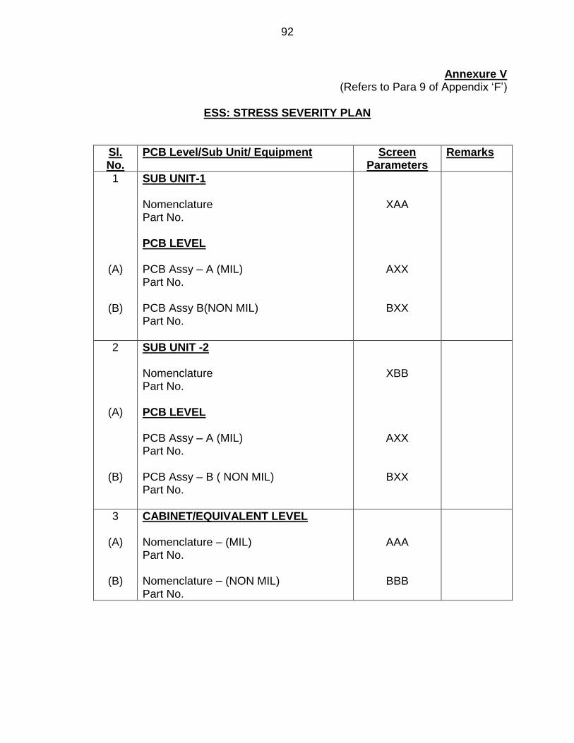
92
Annexure V (Refers to Para 9 of Appendix ‘F’)
ESS: STRESS SEVERITY PLAN
Sl. No.
PCB Level/Sub Unit/ Equipment Screen Parameters
Remarks
1
(A)
(B)
SUB UNIT-1 Nomenclature Part No. PCB LEVEL PCB Assy – A (MIL) Part No. PCB Assy B(NON MIL) Part No.
XAA
AXX
BXX
2
(A)
(B)
SUB UNIT -2 Nomenclature Part No. PCB LEVEL PCB Assy – A (MIL) Part No. PCB Assy – B ( NON MIL) Part No.
XBB
AXX
BXX
3
(A)
(B)
CABINET/EQUIVALENT LEVEL Nomenclature – (MIL) Part No. Nomenclature – (NON MIL) Part No.
AAA
BBB

93
94
Annexure VI (Refers to Para 1(l) of Appendix ‘G’)
THE IN SHOCK POLICY
1. This policy specifies the general guidelines related to the shock resistance and
shock tests required for various equipment fitted onboard IN ships. However, with
advent of new technology and substantial up gradation of shock testing facilities within
the Navy, it has been felt that this policy is not comprehensive and merits reformulation.
2. In order to unambiguously define various issues concerning shock classification
of Marine Engineering equipment designated for usage on board ships, it is imperative
that the guidelines contained in succeeding paragraphs are meticulously followed in
conjunction with BR 3021 (I). The issues that require to be addressed while assessing
the shock grading requirements for new equipment being inducted for onboard usage
are highlighted below:-
(a) Criteria to undertake actual shock testing of the equipment with the
availability of modern theoretical analysis techniques and modeling and
simulation tools.
(b) Criteria for accepting shock calculation in view of availability of modern
theoretical analysis and modeling and simulation tools.
(c) Requirement of shock testing one in a series of equipment or each model
in a series of equipment.
(d) Utilisation of improved infrastructure and capability of indigenous labs for
shock testing of shipboard equipment.
(e) Criteria for the equipment to be shock tested with Shock mounts or for the
equipment to be inherently shock resistant to the specified levels.
(f) Methods to be adopted for acceptance of shock calculations, i.e. Static ‘g’
method or dynamic analysis.
(g) Requirement of individual equipment or complete system (in the case of
mechanically coupled systems) being designed for shock resistance.
3. In order to clarify the above issues and in the light of advancements in modeling
and computing techniques, it is considered essential to introspect and revise the IN

95
shock policy. Therefore, to make the existing policy more explicit, necessary guidelines
for a comprehensive shock policy are promulgated below.
SHIP CLASSIFICATION
4. Based on the role of a ship, the classification to be followed for the purpose of
shock grading is listed below. The list is indicative, however, the “Staff Requirements
should clearly specify the Class based on the specific role of the vessel.
CLASS I CLASS II
Aircraft Carries/ADS Survey Ships/Crafts
Cruisers SDBs
Destroyers FACs
Frigates Submarine Rescue Vessel
Corvettes CG Ships
MCMVs OPVs
Tankers Training Ships
LSTs/LCUs OGTs
Missile Boats Auxiliary Crafts
EQUIPMENT CLASSIFICATION
5. Each equipment on a vessel should be assigned to one of the under mentioned
three categories, based on its critically and function with respect to the role assigned to
the vessel. Each of these categories has different shock resistance requirements, which
are enumerated below in decreasing order of severity.
(a) CATEGORY A. Equipment necessary for the vessel to return to base
under its own power. Such equipment must be capable of surviving the “Mission
Critical” shock loadings, i.e. the vessel must survive a single underwater shock
load as specified for this category, which does not incapacitate the hull, essential
equipment and systems necessary for the ship to return to base under its own
power.
(b) CATEGORY B. Equipment necessary for the vessel to fulfill its assigned
operational role. Such equipment must be capable of surviving the “Mission
Critical” shock loadings, i.e. the vessel must survive a single underwater shock
load as specified for this category, which does not incapacitate the hull, essential
equipment and systems necessary for the ship to undertake its operational role
(combat efficiency).
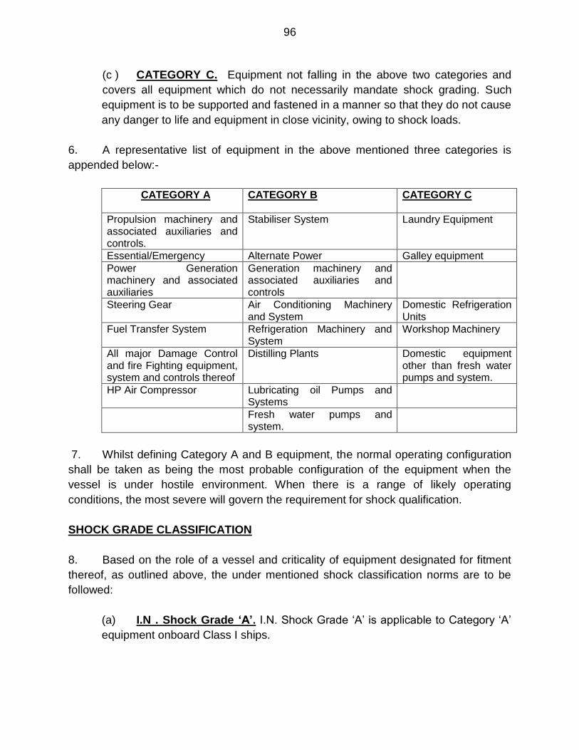
96
(c ) CATEGORY C. Equipment not falling in the above two categories and
covers all equipment which do not necessarily mandate shock grading. Such
equipment is to be supported and fastened in a manner so that they do not cause
any danger to life and equipment in close vicinity, owing to shock loads.
6. A representative list of equipment in the above mentioned three categories is
appended below:-
CATEGORY A CATEGORY B CATEGORY C
Propulsion machinery and associated auxiliaries and controls.
Stabiliser System Laundry Equipment
Essential/Emergency Alternate Power Galley equipment
Power Generation machinery and associated auxiliaries
Generation machinery and associated auxiliaries and controls
Steering Gear Air Conditioning Machinery and System
Domestic Refrigeration Units
Fuel Transfer System Refrigeration Machinery and System
Workshop Machinery
All major Damage Control and fire Fighting equipment, system and controls thereof
Distilling Plants Domestic equipment other than fresh water pumps and system.
HP Air Compressor Lubricating oil Pumps and Systems
Fresh water pumps and system.
7. Whilst defining Category A and B equipment, the normal operating configuration
shall be taken as being the most probable configuration of the equipment when the
vessel is under hostile environment. When there is a range of likely operating
conditions, the most severe will govern the requirement for shock qualification.
SHOCK GRADE CLASSIFICATION
8. Based on the role of a vessel and criticality of equipment designated for fitment
thereof, as outlined above, the under mentioned shock classification norms are to be
followed:
(a) I.N . Shock Grade ‘A’. I.N. Shock Grade ‘A’ is applicable to Category ‘A’
equipment onboard Class I ships.

97
(b) Naval Shock Standards -2 (NSS-2). NSS-2 is applicable to Category ‘B’
equipment onboard Class I ships, besides Category ‘A’ and ‘B’ equipment on
Class II ships.
9. The I.N. Shock Grade ‘A’ curves and NSS II curves are placed at Enclosure 1
and 2 respectively for ready reference.
WEIGHT CLASSIFICATION FOR SHOCK TEST/CALCULATION
10. Shock tests/calculations are to be undertaken based on the weight of the
equipment and facilities available for undertaking shock tests. The equipment are
classified into three weight categories as listed below:-
(a) Up to 600 kg - Light
(b) Between 600-2500 kg - Medium
(c ) Greater than 2500 - Heavy
POLICY FOR TESTING
11. Light and medium category prototype equipment are to be shock tested as a part
development programme. Heavy category prototype equipment are normally not to be
shock tested, however, if there are any features which reflect doubt on the shock
resistance, then shock test is be undertaken.
12. All “Fight of its kind” equipment is to be shock tested under the following
conditions:
(a) If there has been no prototype for the same, or
(b) If the equipment differs considerably from the prototype, or
(c) If any major modification have been undertaken on the equipment, which
would have significant effect on the shock resistance of the equipment.
13. Equipment of a particular model, with any variance to a previously tested model
is to be necessarily shock tested, as the dynamics of such equipment are different from
the originally tested equipment. Further, the OEM will provide test certificate/proof of
shock test calculations for all follow on equipment (for the same type and mounting
98
arrangement). Equipment which have been subjected to shock test are to be “Yellow
Banded” and is to be used for training or in shore based applications.
SHOCK TESTING PROCEDURE
14. The details of procedure to be followed for shock testing of shipboard equipment
are placed at Enclosure 4 for ready reference. MIL-S-901 (D) (Navy) may also be
referred as a guideline document.
STANDARDISATION OF FORMAT FOR SHOCK CALCULATION
15. In case of equipment where shock qualification is to be done on the basis of
shock calculation, the essential criterion to be followed while formulating the shock
calculation report are highlighted at Enclosure 5 for ready reference. As a first step the
Static ‘g’ method is to be used for evaluation of the equipment. However, if the
equipment fails to qualify the Static ‘g’ calculations, the Dynamic Design Analysis
Method (DDAM) or Transient Shock Analysis Method (TSAM) is to be used for
evaluating the equipment.
SHOCK TESTING WITH OR WITHOUT MOUNTS
16. The equipment/assembly to be shock tested is to be mounted on shock and
vibration mounts which will eventually be used for mounting the equipment during actual
shipboard usage. Thus equipment designed for being rigidly mounted in the ship shall
be subjected to shock test in the same state, whilst equipment designed for installation
on flexible mounts shall be subjected to the shock test with the intended mounts in
place. Further the shock attention across the mounts is also to be recorded to
corroborate the efficacy of the mount selection.
SHOCK TESTING OF MECHANICALLY COUPLED SYSTEMS
17. The equipment/assembly to be shock tested is to be essentially fitted with all
associated pipe work, cabling and controls and sensors, besides any other attachments
necessary for normal operation of the entire assembly. Thus, the piping, cabling,
controls and auxiliaries associated with any equipment are to be tested to the first
supporting bracket fixed to some structure other than the equipment, if not integrally
mounted on the equipment itself.
99
TEST FACILITIES
18. Shock testing of various equipments is to be undertaken at NSTL
(Visakhapatnam), unless prior approval for conduct of the same at an alternate location
has been obtained from the Integrated Headquarters of Ministry of Defence
(Navy)/Directorate of Marine Engineering. The details of test facilities available at M/s
NSTL and DMDE are placed at Enclosure 6 for ready reference.
19. Flowchart for Design/Verification checks for shock is placed at Enclosure 7.

100
Enclosure 1

101
Enclosure 2
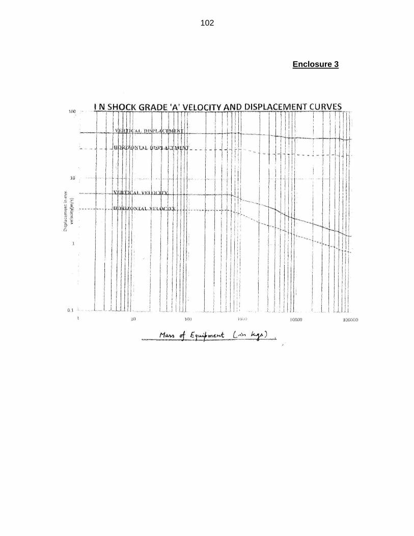
102
Enclosure 3
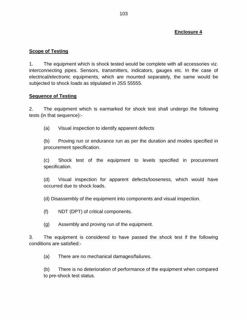
103
Enclosure 4
Scope of Testing
1. The equipment which is shock tested would be complete with all accessories viz.
interconnecting pipes. Sensors, transmitters, indicators, gauges etc. In the case of
electrical/electronic equipments, which are mounted separately, the same would be
subjected to shock loads as stipulated in JSS 55555.
Sequence of Testing
2. The equipment which is earmarked for shock test shall undergo the following
tests (in that sequence):-
(a) Visual inspection to identify apparent defects
(b) Proving run or endurance run as per the duration and modes specified in
procurement specification.
(c) Shock test of the equipment to levels specified in procurement
specification.
(d) Visual inspection for apparent defects/looseness, which would have
occurred due to shock loads.
(d) Disassembly of the equipment into components and visual inspection.
(f) NDT (DPT) of critical components.
(g) Assembly and proving run of the equipment.
3. The equipment is considered to have passed the shock test if the following
conditions are satisfied:-
(a) There are no mechanical damages/failures.
(b) There is no deterioration of performance of the equipment when compared
to pre-shock test status.

104
(c ) There are no cracks, leakages of working medium/control medium or any
other defects that may lead to degradation of characteristics of the article.
(d) There is no change in status of switches (on/off) or malfunctioning of
equipment/skid-mounted sensors, transducers gauges etc.

105
Enclosure 5
GUIDELINES FOR SHOCK QUALIFICATION BY SHOCK CALCULATION
1. The following shall be considered explicitly in the calculations, which shall be
made for each of the principle axes separately:-
(a) The mass of the equipment.
(b) The strength and stiffness of the foundation.
(c) The response of the sub components of the equipment.
(d) The duration of the shock loading
2. The calculation/method employed for evaluation of the centre of gravity of the
complete equipment and individual components are to be clearly indicated.
3. The complete material and physical properties of the components of the
equipment are to be indicated.
4. The natural frequency of the equipment as mounted on the ship is to be either
calculated or determined by tests. On evaluation of the natural frequency, the
equipment/components are classified as either rigid/flexible as per guidelines in BR
3021(I).
5. A Non-Linear Lumped Mass Modeling is to be adopted for evaluation of the
characteristic of the equipment. The Boundary conditions and constraints applicable to
the equipment are to be clearly specified in the model. Advanced techniques such as
Finite Element Analysis and tools such as ANSYS/PAFEC code may be used for the
analysis clearly specifying the number of nodes and elements used for discretizing the
equipment.
6. The “frequency ration” of the natural frequency of the equipment to the Shock
input frequency is to be evaluated as per guidelines in BR 3021(I).
7. The “Shock amplification Factor” and load multiplier required to applied for the
calculations is to be evaluated as per guidelines in BR 3021(I).
106
8. The acceleration, Velocity, Time period values as applicable for the calculations
are to be obtained as per guidelines in BR – 3021(I).
9. The permissible shock design stresses are to be obtained as per guidelines in
BR – 3021(I).
10. The Bending Moment, Shear force, Bending Stresses and displacement as
obtained in the calculations are to be clearly specified for the equipment and each
individual component of the equipment. The effect on various clearances of the
equipment/components is to be clearly stated in the calculations,
11. A flow chart indicating the steps to be undertaken for design/verification checks
for shock is highlighted in the next page.

107
Enclosure 6
DETAILS OF TEST FACILITIES
1. Test facilities Available at NSTL Visakhapatnam. The following infrastructure /
facilities are available for undertaking actual shock testing of equipment:-
S.NO TEST FACILITY PAYLOAD PAYLOAD SIZE
REMARKS
(a) Test machine (Drop test/free fall machine)
up to 600 kg 1m x1m 600kg-90 g
(b) Test machine (Drop test/free fall machine)
up to 1000 kg 1.5x1.5m Max acceleration - 600g Min. weight - 200kg
(c ) Floating Shock Platform (FSP-I small)
Up to 2000kg 2.5 X 1.5 X 1.5m
The platform is floated in NSTL shock tank of size 15mx12mx10m and explosives are used in the rank to create the required shock levels.
(d) Floating Shock Platform (FSP-II Large)
Up to 15000 kg
8x3x2m The platform is floated in NSTL Shock tank of size 15mx12mx10m or in open water and explosives are used in the tank to create the required shock levels
(e) Shock tubes Shock tubes are fabricated to accommodate any size of equipment. Very high levels of shock pulses are channelized in the shock tubes and applied on the test equipment.
2. Test Facilities at DMDE, Secunderabad. DMDE has an impact-testing
machine (K-200M) for subjecting equipment weighing up to 200 kgs to impact
loads.

108
Enclosure 7
<
109

110
NOTES

111
NOTES

112
NOTES

113
NOTES

114
NOTES

115
NOTES
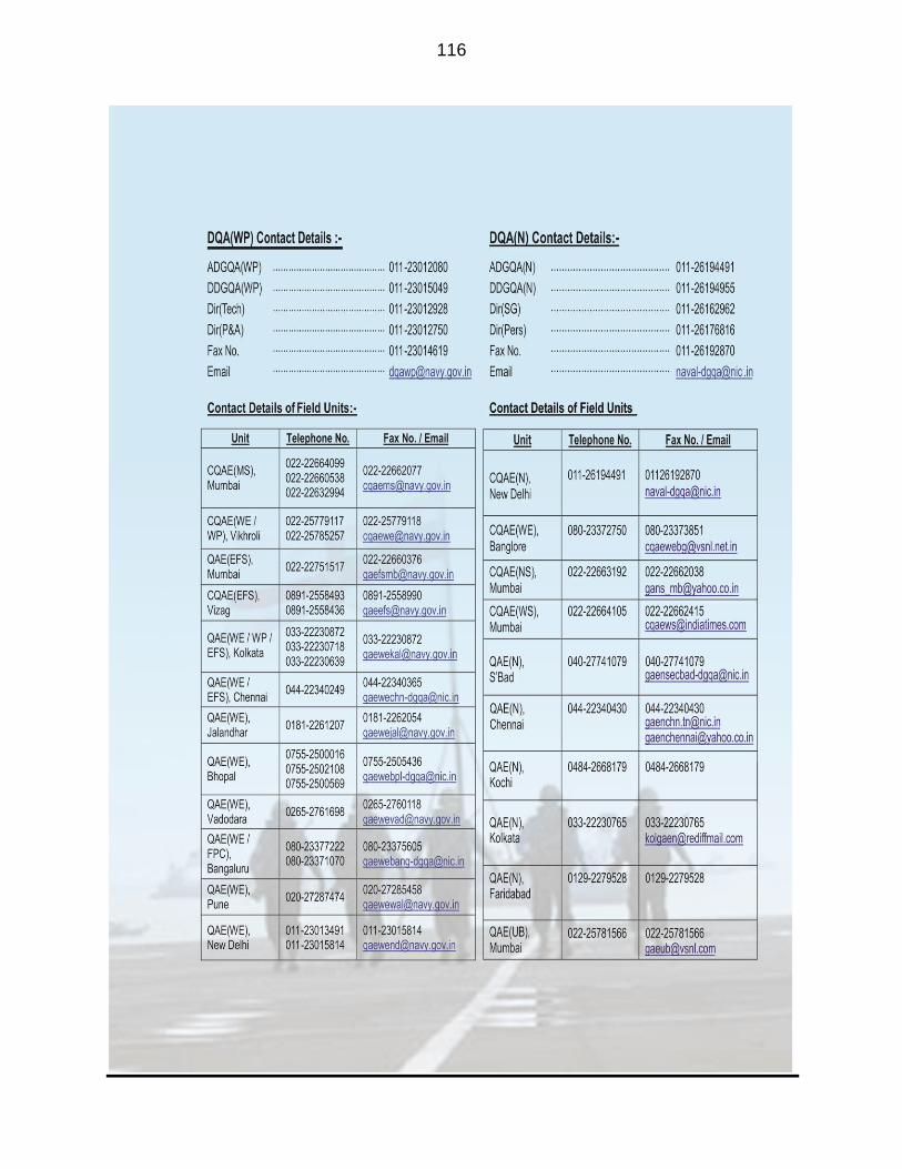
116

117