


Languages
Pages
Legal


Who Wants to Be a CFD Expert?
• In the ME 566 course title, CFD for Engineering Design, what does the acronym CFD stand for?A. Car Free Day
B. Cash Flow Diagram
C. Computational Fluid Dynamics
• Lifelines• Phone a Friend
• Ask the Audience
ME 566 Project
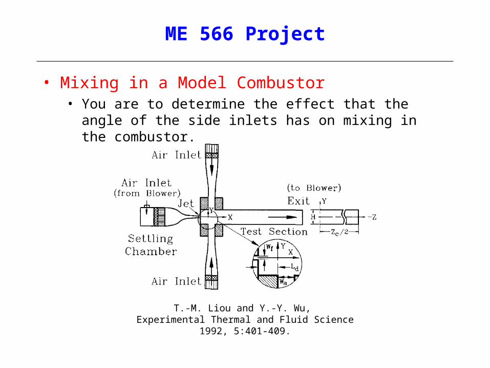
• Mixing in a Model Combustor• You are to determine the effect that the angle of the side inlets has
on mixing in the combustor.
T.-M. Liou and Y.-Y. Wu, Experimental Thermal and Fluid Science 1992, 5:401-409.
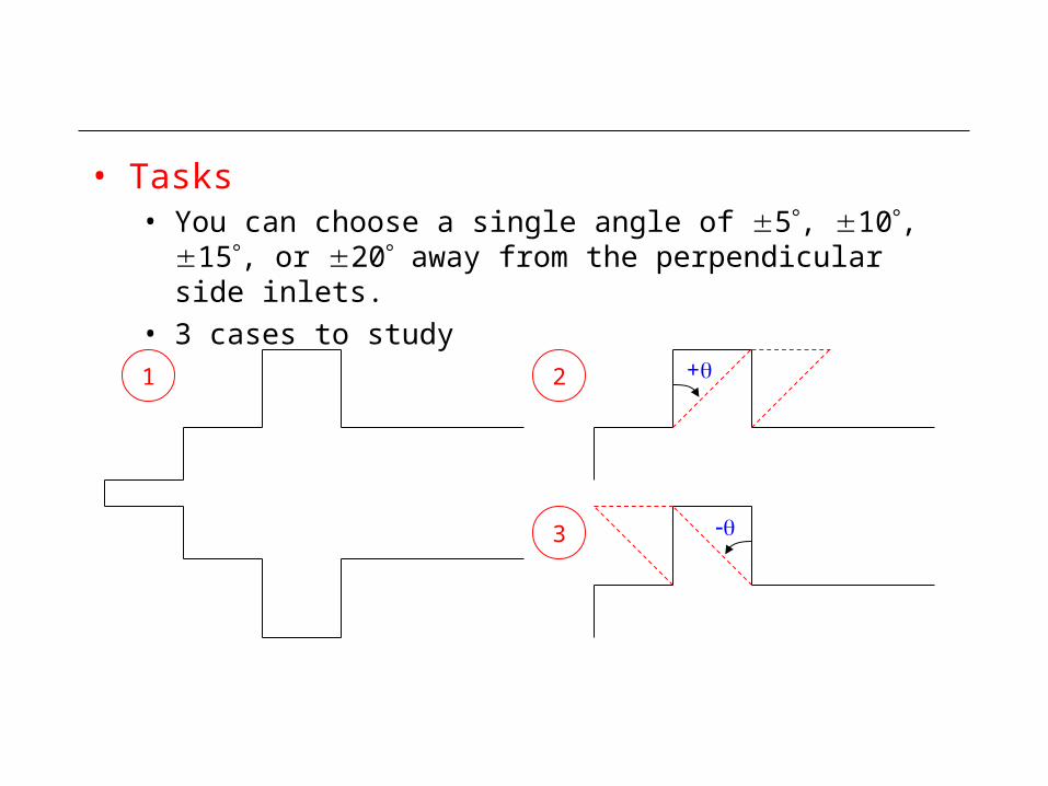
• Tasks• You can choose a single angle of 5, 10, 15, or 20 away
from the perpendicular side inlets.
• 3 cases to study
+
1 2
3

• Physical dimensions of the combustor• The length unit is in mm
X
Y
1.58 30
15
15
15
2000
120
Z
Y
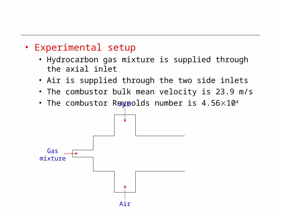
• Experimental setup• Hydrocarbon gas mixture is supplied through the axial inlet
• Air is supplied through the two side inlets
• The combustor bulk mean velocity is 23.9 m/s
• The combustor Reynolds number is 4.56104
Air
Air
Gas mixture

• Comments• The experimental results can be used as a guideline.
• To augment the experimental findings on mixing, you can set the temperatures of the side inlet and axial jets to different values and use temperature as a passive fluid marker (i.e. solve the thermal energy equation with no buoyancy force).
Tside
Taxial
Assume adiabatic at walls
CFX-Pre:- Buoyancy Option: Non Buoyant- Heat Transfer Option: Thermal Energy

Project Report
• You report should include• a comment on the validity of the CFD simulation for the
perpendicular angle based on comparison to experimental data
• a clear statement of your findings on the effect of the side inlet angle on mixing within the combustor
• a clear presentation of the computational model’s geometry, boundary conditions and properties. Wherever possible, quantify the influence that the two most significant model parameters have on your solution
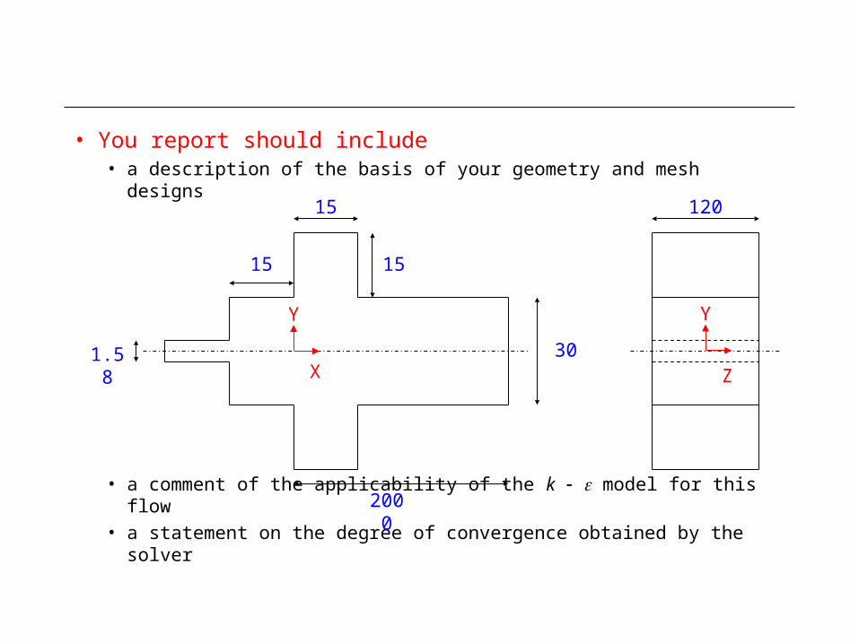
• You report should include• a description of the basis of your geometry and mesh designs
• a comment of the applicability of the k model for this flow
• a statement on the degree of convergence obtained by the solver
X
Y
1.58 30
15
15
15
2000
120
Z
Y
Frequently Asked Questions (FAQs)
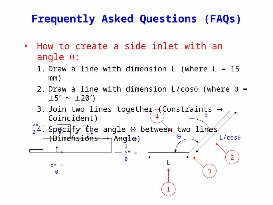
• How to create a side inlet with an angle :1. Draw a line with dimension L (where L = 15 mm)
2. Draw a line with dimension L/cos (where = 5 ~ 20)3. Join two lines together (Constraints Coincident)
4. Specify the angle between two lines (Dimensions Angle)
1
2
4
L
L/cos
3
Y* = 2
Y* = 1
Y* = 0
X* = 0
L
• What fluid properties should be used for hydrocarbon gas mixture?• You can assume the gas mixture has the same properties as air
• What entrance velocity should be used?• One way to find out entrance velocity is to read U/Uref and V/Uref
from Tables 1A and 1B, where Uref = 23.9 m/s
• What turbulence intensity and length scale values should be used?• One way to find out turbulence intensity is to read u’/Uref and
v’/Uref from Tables 1A and 1B
• For length scale, select the turbulence option: Intensity and Auto Compute Length
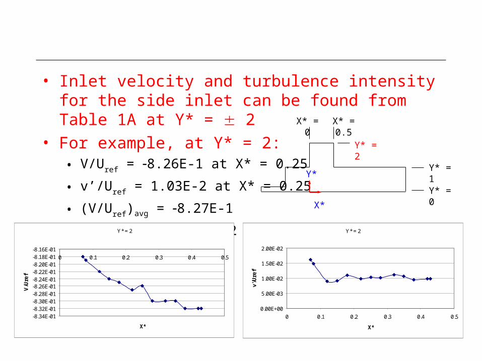
• Inlet velocity and turbulence intensity for the side inlet can be found from Table 1A at Y* = 2
• For example, at Y* = 2:• V/Uref = 8.26E-1 at X* = 0.25
• v’/Uref = 1.03E-2 at X* = 0.25
• (V/Uref)avg = 8.27E-1
• (v’/Uref)avg = 1.09E-2
Y* = 2
Y* = 1
Y* = 0
X* = 0
Y* = 2
-8.34E-01-8.32E-01-8.30E-01-8.28E-01-8.26E-01-8.24E-01-8.22E-01-8.20E-01-8.18E-01-8.16E-01
0 0.1 0.2 0.3 0.4 0.5
X*
V/Uref
X* = 0.5
Y* = 2
0.00E+00
5.00E-03
1.00E-02
1.50E-02
2.00E-02
0 0.1 0.2 0.3 0.4 0.5
X*
v'/Uref
X*
Y*
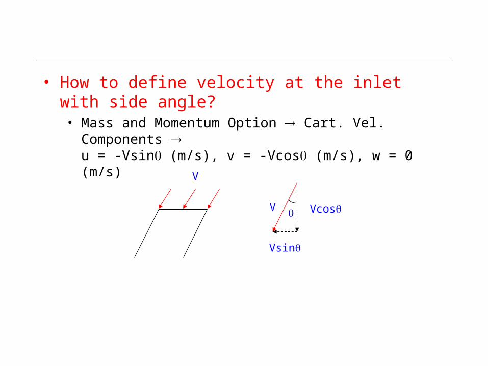
• How to define velocity at the inlet with side angle?• Mass and Momentum Option Cart. Vel. Components
u = -Vsin (m/s), v = -Vcos (m/s), w = 0 (m/s)
V
V Vcos
Vsin

Questions?

Order of Accuracy
• A certain discretisation scheme is used to estimate the temperature in a rectangular fin. The computations are done with a uniform mesh having a spacing of x. Table 1 shows the variation of the predicted heat flux at the base of the fin, , with the mesh spacing.
• Q1: Estimate the order of accuracy of the numerical method. The exact heat flux is 214.3 [watts].
• Q2: The order appears to decrease for the finer meshes. What numerical errors are affecting the solutions obtained with fine meshes?
x [m] [watts]0.05 110.1
0.025 162.80.01 193.8
0.005 204.10.0025 209.2
0.00125 211.90.000625 212.9
bqbq
Table 1
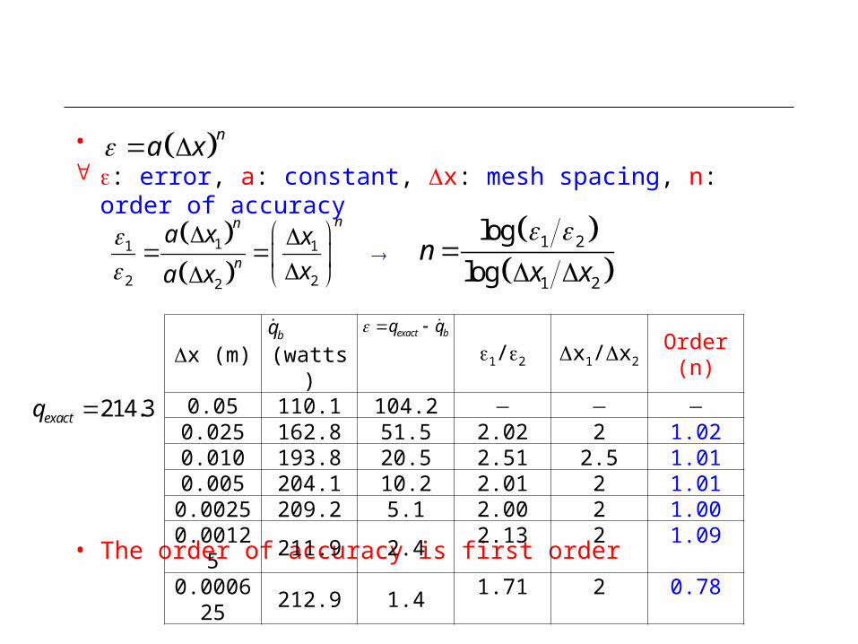
• : error, a: constant, x: mesh spacing, n: order of accuracy
• The order of accuracy is first order
x (m) (watts) 1/2 x1/x2 Order (n)0.05 110.1 104.2
0.025 162.8 51.5 2.02 2 1.020.010 193.8 20.5 2.51 2.5 1.010.005 204.1 10.2 2.01 2 1.01
0.0025 209.2 5.1 2.00 2 1.000.00125 211.9 2.4 2.13 2 1.090.000625 212.9 1.4 1.71 2 0.78
exact bq q bq
na x
11 1
2 22
nn
n
a x x
xa x
1 2
1 2
log
logn
x x
214.3exactq

Who Wants to Be a CFD Expert?
• The order of accuracy appears to decrease for the finer meshes. What numerical errors are affecting the solutions obtained with fine meshes?A. Discretisation error
B. Round-off error
C. Truncation error
• Lifelines• Phone a Friend
• Ask the Audience
x (m) Order (n)0.05 104.2
0.025 51.5 1.020.010 20.5 1.010.005 10.2 1.010.0025 5.1 1.00
0.00125 2.4 1.090.000625 1.4 0.78

Numerical Errors (Sec. 10.2)
• Round-off error• Round-off errors are the result of the computational representation
of real numbers by means of a finite number of significant digits, which is termed the machine accuracy.
• Discretisation error / Truncation error• The discretisation error is associated with the neglected
contributions due to the truncation of high-order terms.
2
2
truncation error
2E P E P
P P
xO x
x x x x
2 2
2 2E PP P
xx
x x
Taylor series expansion
Top Related