


Languages
Pages
Legal


THER
MO
STAT
SINDEX
24 VOLT WI-FI / UTILITY / 4-WIRE / WIRELESS THERMOSTATS 6 – 11 Description Model(s) Page(s) Sensi Wi-Fi Thermostat ................................................................................. 1F86U-42WF ......................................................... 6 – 7 Smart Energy Thermostat ............................................................................. EE542-1Z .............................................................. 8 Easy Install Inspire™ Universal 4-Wire Color Thermostat System ............... 1HDEZ-1521 .......................................................... 9 Easy Install Universal 4-Wire Thermostat Solution ....................................... 1F98EZ-1421, -1441 .............................................. 10 Wireless Easy Install Thermostat System ..................................................... 1F98EZ-1621 ......................................................... 11 Wireless Remote Sensor for Wireless Easy Install ....................................... F145RF-1600 ......................................................... 32
THERMOSTATS
24 VOLT ELECTRONIC / DIGITAL THERMOSTATS 12 – 23 Description Model(s) Page(s) Blue 12” Touchscreen ................................................................................... 1F95 / 1F97 ............................................................ 12 – 13 Blue 6” Thermostats ...................................................................................... 1F95 / 1F95EZ ....................................................... 14 – 15 Blue 4” Thermostats ...................................................................................... 1F80 / 1F80ST / 1F83 / 1F85 / 1F85ST / 1F86 ...... 16 – 17 Blue 2” Thermostats ...................................................................................... 1F80 / 1F82 / 1F86 / 1F86EZ / 1F89 / 1F89EZ ...... 18 – 19 Classic 80 Series Thermostats ...................................................................... 1F80 / 1F82 / 1F85 / 1F87 / 1F89 .......................... 20 – 21 70 Series Thermostats .................................................................................. 1E78 / 1F72 / 1F78 / 1F79 ..................................... 22 – 23
24 VOLT MECHANICAL THERMOSTATS 24 – 25 Description Model(s) Page(s) Heating / Cooling, Horizontal / Vertical Thermostats ..................................... 1E30N / 1E50N / 1E56N / 1F56N .......................... 24 Economy Mechanical Thermostats ............................................................... 1C20 / 1C21 / 1C26 ............................................... 25
LINE VOLTAGE THERMOSTATS 26 – 32 Description Model(s) Page(s) Instant Expert ................................................................................................ Line Voltage Thermostat Selection Guide ......... 26 Line Voltage Digital Thermostat for Electric Heat Applications ...................... 1E65-144 ............................................................... 27 Line Voltage Baseboard Thermostats ........................................................... 1A65 / 1A66 / 1G65 / 1G66 ................................... 28 Line Voltage Light Duty and Heavy Duty Thermostats .................................. 1A10 / 1A16 / S29 ................................................. 29 Line Voltage Light Duty Fan Coil Thermostat ................................................ 1A11-2 ................................................................... 30 Line Voltage Heavy Duty Heating and Cooling Thermostats ......................... 201-8 / 179-1 .......................................................... 31 Line Voltage Heating Thermostats ................................................................ 152 ......................................................................... 32
THERMOSTAT PARTS AND ACCESSORIES 36
REMOTE SENSORS FOR THERMOSTATS – 24 VOLT 32 – 33 Description Model(s) Page(s) Wireless Remote Sensor for Wireless Easy Install ....................................... F145RF-1600 ......................................................... 32 Wired Remote Sensors for 24V Thermostats ................................................ F145-1328, -1378 .................................................. 33
THERMOSTAT GUARDS 34 – 35 Description Model(s) Page(s) Thermostat Guards, Plastic ........................................................................... F29 ......................................................................... 34 Thermostat Guards, Metal ............................................................................. F29 ......................................................................... 35
www.white-rodgers.com 5

THER
MO
STAT
S
www.white-rodgers.com6
SENSI™ WI-FI THERMOSTAT
1F86U-42WF
SENSI WI-FI THERMOSTAT – REMOTE ACCESS FROM SMARTPHONE, TABLET OR PCSensi App Connects Thermostat to Home Wi-Fi Router – No Additional Accessories/Gateway Required
FEATURES•Easytoinstall.Simpletoconnect.•No“Cwire”requiredformostHVACapplications–forfasterandeasierinstalls.•Keepsyourcontactinformationinyourcustomer’ssmartphoneortablet– so you are just a tap away when service is needed.•SensiThermostatoperateslikeastandardthermostatwhen not connected to Wi-Fi.•5-YearLimitedWarranty.
SPECIFICATIONSElectrical Rating:Battery Power ....................................... 0 to 30 VAC, 50/60 Hz or DCTerminal Load ....................................... 0.05 to 1.5 Amps (load per terminal) 1.5 Amps maximum load (all terminals combined)Setpoint Range ..................................... 45 to 99°F (7 to 37°C)Rated Differentials: Fast Med. Slow Heat (Single Stage/ Multi-Stage) ....... 0.4°F 0.6°F 1.7°F Cool (Single Stage/Multi-Stage) ........ 0.9°F 1.2°F 1.7°F Heat Pump ......................................... 0.9°F 1.2°F 1.7°F Aux. Heat ........................................... 0.6°F 1.7°FOperating Humidity ............................... 90% non-condensing max.Standard Systems ................................ Single Stage gas, oil, electric Single Stage heat pump Multi-Stage gas, oil, electric Multi-Stage heat pump Dimension............................................. 33/4”H x 514/16”W x 12/16”D
PARTS AND ACCESSORIES See end of thermostats section for additional parts and accessories
•F29-0198—ThermostatGuards–Clear•F61-2663—Wallplate63/4”W x 41/2”H
UNIVERSAL – 4 HEAT / 2 COOL SENSI WI-FI THERMOSTAT
SingleStage
Multi-Stage
HeatPump Programs Model Applications
Ther
mos
tat P
ower
Sou
rce*
Selectable Performance FeaturesComfort and Convenience
Features Terminals
Stages Heat/Coolby System
Program Options
ModelNumber
Gas
/ O
il / E
lect
ric
3 W
ire Z
one
Valv
e
Mill
ivol
t Com
patib
le
Aut
o C
hang
eove
r
Prog
ram
mab
le F
an
Ener
gy A
war
e
Early
Sta
rt R
ecov
ery
Dua
l Fue
l Hea
t Sta
ges
HP/
Gas
Key
pad
Lock
out
Indo
or R
emot
e Se
nsor
Out
door
R
emot
e Se
nsor
Sele
ctab
le °
F/ °
C
Roo
m H
umid
ity D
ispl
ay
Setp
oint
Tem
pera
ture
Lim
it
Ligh
ted
Dis
play
‡
Aud
ible
Fee
dbac
k
Perm
anen
t Mem
ory
1/1 2/2 4/2 7-day, Ø 1F86U-42WF
B,HPA 2/2 RC, RH, C, W/E, W2,
Y, Y2, O/B, G, L
* B = Battery Powered ‡ = Optional Continuous Display Light with "C Wire" Connection H = Hardwired (Requires Common) PA = Power Stealing Battery Assist
24 VOLT
?PAGES 128–129
TECHNICAL HELP
ConnectionandConfiguration .....................................................See pages 128–129

THER
MO
STAT
S
www.white-rodgers.com 7
Installs lIke a standard thermostatConnect it to the internet or simply install Sensi and let the homeowner connect it at their convenience.10 ConneCts wIth a smartPhone
Step-by-step instructions make it easy to install and pair Sensi to the home router.9
no C wIre needed on most systems Walk in the door knowing Sensi will work – even in most of the 60% of homes that don’t have a common wire.
8 ComPlete ComFort Control For any CUstomer Sensi is priced to make Wi-Fi thermostats a reality for all customers not just the high-end homeowner.
7 more rePeat BUsIness Be one touch away when your customer needs service with your company information stored in the Sensi mobile app.5
Ways to catch the Wi-Fi wave withthe Sensi™ thermostat & mobile app
Top TEN
no Follow UP Call Not only is Sensi easy to use, it meets Energy AwareTM standards for precision, reliability and accurate control.
6
Promote yoUr BUsIness Get customer referrals when you register for the Sensi Branding Program. Visit SensiRegistration.com to sign up today.4
enhanCe yoUr rePUtatIon Consumers are looking for Wi-Fi thermostats. Offer them Sensi so they don’t have to look any further.
3 Grow yoUr thermostat sales Three out of four homes have Wi-Fi. Now there’s a thermostat simple enough for all of them.
2 emPower yoUr CUstomer to take Control oF theIr home ComFort. They will Thank you for iT!1

THER
MO
STAT
S
www.white-rodgers.com8
SMART ENERGY THERMOSTAT
SPECIALTY 24 VOLT
EE542-1Z
PROGRAMMABLE THERMOSTAT AND WHOLE HOME ENERGY MONITORThe Smart Energy Thermostat is Much More than a Thermostat. ItWirelesslyPairswithYourCustomer’sSmartMetertoProvideUnprecedented Insight into Whole Home Electricity Usage – which EnablesYourCustomerstoReduceTheirUtilityBillsbyMakingBetterDecisions About how and when to Use Electricity
FEATURES•Title24compliantpernewresidentialbuildingcodeinCA.•UniversalHVACsystemcompatibility(4heat/2cool).•7dayprogrammingflexibility.•Patentedsensor-lessdualfuelcapability.•Largebacklitdot-matrixdisplay(5sq.”) for optimal readability.•+/-1ºtemperaturecontrolaccuracyensuresconsistentcomfort.•OnetouchAWAYkeyinstantlyengagesawaymodetohelpsavemoney.•Energymonitorallowscustomertosetamonthlybudgetforwholehomeelectricity useandthentrackdailyusagecostsagainstittohelpreduceenergycosts*.•Currentpriceofelectricitypresentedonthehomescreenandtri-colorLEDlets customerknowwhenthepriceofelectricityishigherthannormal*.•PriceProtection™canbeconfiguredtoautomaticallyadjustthetemperaturein home when the price of electricity is high*.•Monthtodateheatingandcoolingcostestimates*.•MessageInboxenablescustomertoreceiveimportantinformationfromutility provider(i.e.notificationofpotentialdisruptiontopowersupply).•RequiresC-wireforpower(nobatteriesrequired).* Feature requires utility to push electricity pricing data through the smart meter (via ZigBee SE Price Cluster.
SPECIFICATIONSElectrical Rating:Hardwire ............................................... 20 to 30 VACTerminal Load ....................................... 1.5A per terminal, 2.0A maximum all terminals combined Setpoint Range ..................................... 45 to 99°F (7 to 37°C) Rated Differentials: ............................... Heat 0.6°F; Cool 1.2°FOperating Humidity ............................... 90% non-condensing maximum
PARTS AND ACCESSORIES See end of thermostats section for additional parts and accessories
SingleStage
Multi-Stage
HeatPump Programs Model Applications
Inte
rfac
e Po
wer
Sou
rce*
Selectable Performance Features
Comfort and Convenience
Features Terminals
Stages Heat/Coolby System
Program Options
ModelNumber
Gas
/ O
il / E
lect
ric
3 W
ire Z
one
Valv
e
Mill
ivol
t Com
patib
le
Aut
o C
hang
eove
r
Prog
ram
mab
le F
an
Ener
gy M
gt. R
ecov
ery
Dua
l Fue
l Con
trol
Key
pad
Lock
out
Dis
play
Siz
e(S
quar
e in
ches
)
Ligh
ted
Dis
play
Aud
ible
Fee
dbac
k
Igni
tion
Mod
ule
Res
et
Perm
anen
t Mem
ory
RC, RH, C, W/E, W2, Y, Y2, O/B, G, L
1/1 2/2 4/2 7, Ø EE542-1Z 3 H 3 3 3 3 6.0 3 3 3 3
* H = Hardwired (Requires Common)
Settings
Intuitive menu design and familiar5-way navigation pad make this one ofthe easiest to use energy managementproducts on the market.
Large, crisp, dot matrix display makesit easy for customers to track theirenergy use against a monthly budget.
Message inbox with unread mallnotification provides an easy way for utilities to stay in touch with customers.
Usage this Month: $86.22Over Budget By: $11.02
$5Daily Budget
Home
Home More
Fan Auto > Clock >Schedules On >Price Protection >Alerts >
Inbox
Home
● 2:39 pm 5/07/14 >● Cost Alert 5/03/14 >● 12:01 am 5/02/14 > Air Filter 4/23/14 > 5:11 pm 4/18/14 >
DISPLAY MENU
Settings
Intuitive menu design and familiar5-way navigation pad make this one ofthe easiest to use energy managementproducts on the market.
Large, crisp, dot matrix display makesit easy for customers to track theirenergy use against a monthly budget.
Message inbox with unread mallnotification provides an easy way for utilities to stay in touch with customers.
Usage this Month: $86.22Over Budget By: $11.02
$5Daily Budget
Home
Home More
Fan Auto > Clock >Schedules On >Price Protection >Alerts >
Inbox
Home
● 2:39 pm 5/07/14 >● Cost Alert 5/03/14 >● 12:01 am 5/02/14 > Air Filter 4/23/14 > 5:11 pm 4/18/14 >
ENERGY MONITOR
?PAGES
130
TECHNICAL HELP
Connections.................................................................................See page 130

THER
MO
STAT
S
?PAGES
127
TECHNICAL HELP
Connections....................................................................................See page 127
www.white-rodgers.com 9
EASY INSTALLTHERMOSTAT
1HDEZ-1521 Includes User Interface and
Equipment Control
INSPIRE™ UNIVERSAL 4-WIRE COLOR THERMOSTAT SYSTEMUpgradeSingleStageApplicationstoPremiumHigh-EfficiencySystems (Staging, Heat Pump or Heat Pump with Dual Fuel) – Using Existing 4 Wires
FEATURES•Reusableplug-inconfigurationtool–eliminatesmultipletripsupanddownstairs during set up and system testing.•USBporttoquicklyuploadyourfavoriteInstallationSettings,Programsand personalized Company Contact Information.•5/8”thinprofilewithvibrantcolordisplay.•ColorcodedLEDsprovidepositivefeedbackforeasysetup.•Dehumidification,humidification.
DIMENSIONInterface ..................... 31/4”H x 61/8”W x 5/8”DControl ........................ 51/2”H x 53/4”W x 11/2”D
SPECIFICATIONSElectrical Rating:Hardwire . . . . . . . . . . . . . . . . . . . . . . . . 20-30 VAC, NEC Class II 50/60Hz or DCTerminal Load. . . . . . . . . . . . . . . . . . . . 1.5 A per terminal, 2.5 A maximum load (all terminals combined)Setpoint Range. . . . . . . . . . . . . . . . . . . 45 to 99°F (7 to 37°C)Rated Differential . . . . . . . . . . . . . . . . . Heat 0.6°F; Cool 1.2°FOperating Ambient . . . . . . . . . . . . . . . . 32to+105°F(0to+41°C)–Interface -30to+150°F(-34to66°C)–ControlOperating Humidity Range . . . . . . . . . . 90% non-condensing maximum
PARTS AND ACCESSORIES See end of thermostats section for additional parts and accessories
•F4-1400—ThermostatPlug-inConfigurationTool•F145-1378—OutdoorRemoteSensor•F29-0198—LockingThermostatGuard-ClearPlastic•F29-0220—LockingThermostatGuard-Metal,SolidBase•F29-0222—LockingThermostatGuard-Metal,RingBase
INSPIRE™ UNIVERSAL 4-WIRE COLOR THERMOSTAT SYSTEM
24 VOLT
SingleStage
Multi-Stage
HeatPump Programs Model Applications
Ther
mos
tat P
ower
Sou
rce*
Selectable Performance Features
Dis
play
Siz
e (S
quar
e in
ches
)
Terminals
Stages Heat/Coolby System
Program Options
Periodsper dayOptions
ModelNumber
Gas
/ O
il / E
lect
ric
3 W
ire Z
one
Valv
e
Mill
ivol
t Com
patib
le
Hum
idity
Con
trol
(H)-H
umid
ity /
(D)-D
ihum
idity
Aut
o C
hang
eove
r
Prog
ram
mab
le F
an
Ener
gy A
war
e
Com
fort
Ale
rt®
A.C
. Sys
tem
Pro
tect
ion
(P)-P
assi
ve/(A
)-Act
ive§
Dua
l Fue
l Hea
t Pum
p C
ontr
ol(L
)-Log
ic/(O
)-Out
door
Sen
sor
Dua
l Fue
l Hea
t Sta
ges
HP/
Gas
Aux
. Hea
t Loc
kout
with
Out
door
Sen
sor
Key
pad
Lock
out
(T)-T
otal
/(P)-P
artia
lSe
tpoi
nt T
empe
ratu
re L
imits
Adj
usta
ble
Max
./Min
.In
door
Rem
ote
Sens
ors
Max
. Num
ber +
The
rmos
tat
Ave
rage
and
/or W
eigh
ted
Rem
ote
Tem
pera
ture
Sen
sing
RC, RH, C, W/E, W2, Y, Y2, O/B, G, L, +, S, -,
DHM, DHM2, HM, HM2, R, 1, 2, C- Thermostat 1,
2, C, R
1/1 2/2 4/2 7, Ø 4, Ø 1HDEZ-1521 H,D H A 0 ‡ 2/2 1 5.5
*H = Hardwired (Requires Common) When used with an outdoor sensor provides options tolockoutauxiliaryheataboveselectedoutdoor temperature.
THER
MO
STAT
S
www.white-rodgers.com10
EASY INSTALLTHERMOSTAT
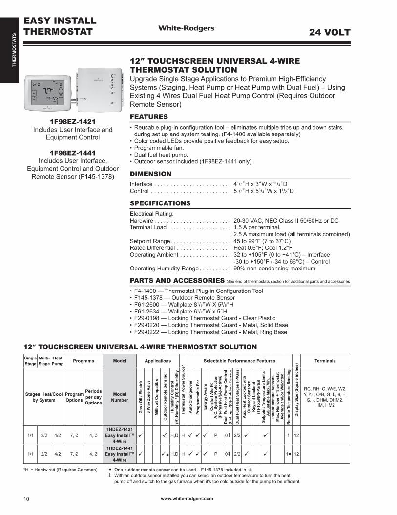
12” TOUCHSCREEN UNIVERSAL 4-WIRE THERMOSTAT SOLUTION UpgradeSingleStageApplicationstoPremiumHigh-EfficiencySystems (Staging, Heat Pump or Heat Pump with Dual Fuel) – Using Existing 4 Wires Dual Fuel Heat Pump Control (Requires Outdoor Remote Sensor)
FEATURES•Reusableplug-inconfigurationtool–eliminatesmultipletripsupanddownstairs. during set up and system testing. (F4-1400 available separately)•ColorcodedLEDsprovidepositivefeedbackforeasysetup.•Programmablefan.•Dualfuelheatpump.•Outdoorsensorincluded(1F98EZ-1441only).
DIMENSIONInterface . . . . . . . . . . . . . . . . . . . . . . . . 41/2”H x 3”W x 11/4”D Control . . . . . . . . . . . . . . . . . . . . . . . . . 51/2”H x 53/4”W x 11/2”D
SPECIFICATIONSElectrical Rating:Hardwire . . . . . . . . . . . . . . . . . . . . . . . . 20-30 VAC, NEC Class II 50/60Hz or DCTerminal Load. . . . . . . . . . . . . . . . . . . . 1.5 A per terminal, 2.5 A maximum load (all terminals combined)Setpoint Range. . . . . . . . . . . . . . . . . . . 45 to 99°F (7 to 37°C)Rated Differential . . . . . . . . . . . . . . . . . Heat 0.6°F; Cool 1.2°FOperating Ambient . . . . . . . . . . . . . . . . 32to+105°F(0to+41°C)–Interface -30to+150°F(-34to66°C)–ControlOperating Humidity Range . . . . . . . . . . 90% non-condensing maximum
PARTS AND ACCESSORIES See end of thermostats section for additional parts and accessories
•F4-1400—ThermostatPlug-inConfigurationTool•F145-1378—OutdoorRemoteSensor•F61-2600—Wallplate81/8”W X 53/8”H•F61-2634—Wallplate61/2”W x 5”H•F29-0198—LockingThermostatGuard-ClearPlastic•F29-0220—LockingThermostatGuard-Metal,SolidBase•F29-0222—LockingThermostatGuard-Metal,RingBase
1F98EZ-1421 Includes User Interface and
Equipment Control
1F98EZ-1441 Includes User Interface,
Equipment Control and Outdoor Remote Sensor (F145-1378)
24 VOLT
12” TOUCHSCREEN UNIVERSAL 4-WIRE THERMOSTAT SOLUTION SingleStage
Multi-Stage
HeatPump Programs Model Applications
Ther
mos
tat P
ower
Sou
rce*
Selectable Performance Features
Dis
play
Siz
e (S
quar
e in
ches
) Terminals
Stages Heat/Coolby System
Program Options
Periodsper dayOptions
ModelNumber
Gas
/ O
il / E
lect
ric
3 W
ire Z
one
Valv
e
Mill
ivol
t Com
patib
le
Out
door
Rem
ote
Sens
ing
Hum
idity
Con
trol
(H)-H
umid
ity /
(D)-D
ihum
idity
Aut
o C
hang
eove
r
Prog
ram
mab
le F
an
Ener
gy A
war
eC
omfo
rt A
lert
®A
.C. S
yste
m P
rote
ctio
n(P
)-Pas
sive
/(A)-A
ctiv
e§D
ual F
uel H
eat P
ump
Con
trol
(L)-L
ogic
/(O)-O
utdo
or S
enso
r
Dua
l Fue
l Hea
t Sta
ges
HP/
Gas
Aux
. Hea
t Loc
kout
with
Out
door
Sen
sor
Key
pad
Lock
out
(T)-T
otal
/(P)-P
artia
lSe
tpoi
nt T
empe
ratu
re L
imits
Adj
usta
ble
Max
./Min
.In
door
Rem
ote
Sens
ors
Max
. Num
ber +
The
rmos
tat
Ave
rage
and
/or W
eigh
ted
Rem
ote
Tem
pera
ture
Sen
sing
RC, RH, C, W/E, W2, Y, Y2, O/B, G, L, 6, +,
S, -, DHM, DHM2, HM, HM2
1/1 2/2 4/2 7, Ø 4, Ø1HDEZ-1421
Easy Install™4-Wire
H,D H P 0 ‡ 2/2 1 12
1/1 2/2 4/2 7, Ø 4, Ø1HDEZ-1441
Easy Install™4-Wire
■ H,D H P 0 ‡ 2/2 1■ 12
*H = Hardwired (Requires Common) ■ Oneoutdoorremotesensorcanbeused–F145-1378includedinkit ‡ With an outdoor sensor installed you can select an outdoor temperature to turn the heat pumpoffandswitchtothegasfurnacewhenit'stoocoldoutsideforthepumptobeefficient.
THER
MO
STAT
S
www.white-rodgers.com 11
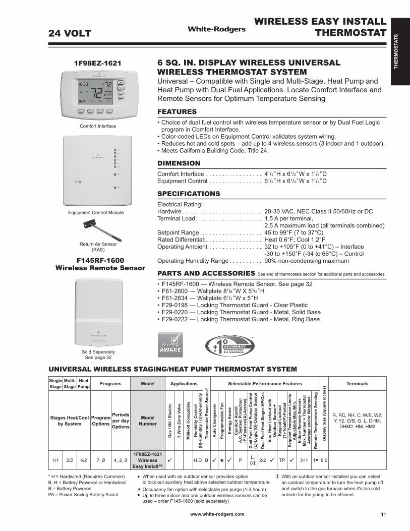
24 VOLTWIRELESS EASY INSTALL
THERMOSTAT
6 SQ. IN. DISPLAY WIRELESS UNIVERSAL WIRELESS THERMOSTAT SYSTEM Universal – Compatible with Single and Multi-Stage, Heat Pump and Heat Pump with Dual Fuel Applications. Locate Comfort Interface and Remote Sensors for Optimum Temperature Sensing
FEATURES•ChoiceofdualfuelcontrolwithwirelesstemperaturesensororbyDualFuelLogic
program in Comfort Interface. •Color-codedLEDsonEquipmentControlvalidatessystemwiring.•Reduceshotandcoldspots–addupto4wirelesssensors(3indoorand1outdoor).•MeetsCaliforniaBuildingCode,Title24.
DIMENSIONComfort Interface . . . . . . . . . . . . . . . . . 41/2”H x 61/2”W x 11/4”D Equipment Control . . . . . . . . . . . . . . . . 61/2”H x 61/2”W x 11/2”D
SPECIFICATIONSElectrical Rating:Hardwire . . . . . . . . . . . . . . . . . . . . . . . . 20-30 VAC, NEC Class II 50/60Hz or DCTerminal Load. . . . . . . . . . . . . . . . . . . . 1.5 A per terminal, 2.5 A maximum load (all terminals combined)Setpoint Range. . . . . . . . . . . . . . . . . . . 45 to 99°F (7 to 37°C)Rated Differential:. . . . . . . . . . . . . . . . . Heat 0.6°F; Cool 1.2°FOperating Ambient . . . . . . . . . . . . . . . . 32to+105°F(0to+41°C)–Interface -30to+150°F(-34to66°C)–ControlOperating Humidity Range . . . . . . . . . . 90% non-condensing maximum
PARTS AND ACCESSORIES See end of thermostats section for additional parts and accessories
•F145RF-1600—WirelessRemoteSensor.Seepage32•F61-2600—Wallplate81/8”W X 53/8”H•F61-2634—Wallplate61/2”W x 5”H•F29-0198—LockingThermostatGuard-ClearPlastic•F29-0220—LockingThermostatGuard-Metal,SolidBase•F29-0222—LockingThermostatGuard-Metal,RingBase
1F98EZ-1621
Comfort Interface
Equipment Control Module
Return Air Sensor(RAS)
Sold SeparatelySee page 32
F145RF-1600Wireless Remote Sensor
UNIVERSAL WIRELESS STAGING/HEAT PUMP THERMOSTAT SYSTEMSingleStage
Multi-Stage
HeatPump Programs Model Applications
Ther
mos
tat P
ower
Sou
rce*
Selectable Performance Features
Dis
play
Siz
e (S
quar
e in
ches
) Terminals
Stages Heat/Coolby System
Program Options
Periodsper dayOptions
ModelNumber
Gas
/ O
il / E
lect
ric
3 W
ire Z
one
Valv
e
Mill
ivol
t Com
patib
le
Hum
idity
Con
trol
(H)-H
umid
ity /
(D)-D
ihum
idity
Aut
o C
hang
eove
r
Prog
ram
mab
le F
an
Ener
gy A
war
eC
omfo
rt A
lert
®A
.C. S
yste
m P
rote
ctio
n(P
)-Pas
sive
/(A)-A
ctiv
e§D
ual F
uel H
eat P
ump
Con
trol
(L)-L
ogic
/(O)-O
utdo
or S
enso
r
Dua
l Fue
l Hea
t Sta
ges
HP/
Gas
Aux
. Hea
t Loc
kout
with
Out
door
Sen
sor
Key
pad
Lock
out
(T)-T
otal
/(P)-P
artia
lSe
tpoi
nt T
empe
ratu
re L
imits
Adj
usta
ble
Max
./Min
.In
door
Rem
ote
Sens
ors
Max
. Num
ber +
The
rmos
tat
Ave
rage
and
/or W
eigh
ted
Rem
ote
Tem
pera
ture
Sen
sing
R, RC, RH, C, W/E, W2, Y, Y2, O/B, G, L, DHM,
DHM2, HM, HM2
1/1 2/2 4/2 7, Ø 4, 2, Ø1F98EZ-1621
Wireless Easy Install™
H,D B P L,0 ‡ 2/2 TP 3+1 1● 6.0
When used with an outdoor sensor provides option tolockoutauxiliaryheataboveselectedoutdoortemperature.Occupancy fan option with selectable pre-purge (1-3 hours)● Up to three indoor and one outdoor wireless sensors can be used – order F145-1600 (sold separately)
‡ With an outdoor sensor installed you can select an outdoor temperature to turn the heat pump off and switch to the gas furnace when it's too cold outsideforthepumptobeefficient.
* H = Hardwired (Requires Common) B, H = Battery Powered or HardwiredB = Battery PoweredPA = Power Saving Battery Assist

THER
MO
STAT
S
BLUE 12” TOUCHSCREEN - UNIVERSAL AND SINGLE STAGE THERMOSTATS - 12 SQ. IN. DISPLAYBlue Models Offer the Ultimate in Comfort, Features, Performance and Visibility
FEATURES•Universalmodelsquicklyconfigureforsinglestage,multi-stageorheatpumpand heat pump dual fuel systems - programmable or non-programmable.•Humidity controloffershumidification/dehumidification.•Commercial offers occupied damper or economizer control.•Staging control for nearly all conventional and heat pump systems.•Single stage model compatible with all single stage systems low voltage, 750 mV and 3-wire zone systems.•HeatPumpdualfueloptioneliminatestheneedforafossilfuelkit.•Automaticchangeoveroption.•Programfanoptions.•Keypadlockoutandsetpointtemperaturelimitoptions.• Indoorremotesensorforaveragingoption.•Outdoorremotesensoroption.AddtoUniversalmodelsforoutdoortempreadingor, on select models, dual fuel balance point and outdoor thermostat functions.•Dualpower–hardwireand/orbatteryorTripower–hardwireand/orbatterywith system assist.
SPECIFICATIONSElectrical Rating:Hardwire . . . . . . . . . . . . . . . . . . . . . . . . 20-30 VAC, NEC Class II 50/60HzBattery Power. . . . . . . . . . . . . . . . . . . . mV to 30 VAC, NEC Class II, 50/60 Hz or DCTerminal Load. . . . . . . . . . . . . . . . . . . . 1.5 A per terminal, 2.5 A maximum all terminals combinedSetpoint Range. . . . . . . . . . . . . . . . . . . 45 to 99°F (7 to 37°C)Rated Differentials: Fast Med. Slow Heat (Single Stage/Multi-Stage) . . . . 0.4°F 0.6°F 1.7°F Cool (Single Stage/Multi-Stage) . . . . 0.9°F 1.2°F 1.7°F Heat Pump. . . . . . . . . . . . . . . . . . . . . 0.9°F 1.2°F 1.7°F Emer. Heat. . . . . . . . . . . . . . . . . . . . . 0.6°F 1.7°FOperating Ambient . . . . . . . . . . . . . . . . 32to+105°F(0to+41°C)Operating Humidity. . . . . . . . . . . . . . . . 90% non-condensing max.Shipping Temperature Range. . . . . . . . -4to+150°F(-20to65°C)Dimension. . . . . . . . . . . . . . . . . . . . . . . 49/16”H x 513/16”W x 113/16”D
PARTS AND ACCESSORIES See end of thermostats section for additional parts and accessories
•F145-1328—Indoorremotesensor.Seepage33•F145-1378—Outdoorremotesensor.Seepage33•F61-2600—Wallplate81/8”W x 53/8”H•F61-2634—Wallplate61/2”W x 5”H(ororderF61-2648–6packofF61-2634)•F29-0198—LockingThermostatGuard-ClearPlastic•F29-0220—LockingThermostatGuard-Metal,SolidBase•AdditionalThermostatGuards—seepages34–35forquickselectionoptions
1F95-1291
1F95-1277
F145-1328Indoor Remote Sensor
F145-1378Outdoor Remote Sensor
www.white-rodgers.com12
24 VOLTBLUE 12” TOUCHSCREENTHERMOSTATS

THER
MO
STAT
S
SINGLE STAGE THERMOSTAT – BLUE 12” THERMOSTATS
SingleStage
Multi-Stage
HeatPump Programs Model Applications
Ther
mos
tat P
ower
Sou
rce*
Selectable Performance FeaturesComfort and Convenience
Features Terminals
Stages Heat/Coolby System
Program Options
Periods Per Day Options
ModelNumber
Gas
/ O
il / E
lect
ric
3 W
ire Z
one
Valv
e
Mill
ivol
t Com
patib
le
Econ
omiz
er
Hum
idity
Con
trol
(H)-H
umid
ity /
(D)-D
ehum
idify
Aut
o C
hang
eove
r
Prog
ram
mab
le F
an
Ener
gy M
gt. R
ecov
ery
Dua
l Fue
l Hea
t Pum
p C
ontr
ol(L
)-Log
ic /
(O)-O
utdo
or S
enso
rK
eypa
d Lo
ckou
t(T
)-Tot
al /
(P)-P
artia
lSe
t-Poi
nt T
empe
ratu
re L
imits
Adj
usta
ble
Max
/Min
Indo
or R
emot
e Se
nsor
sM
ax. N
umbe
r + T
herm
osta
tAv
erag
e an
d/or
Wei
ghte
dO
utdo
or R
emot
e Se
nsor
Dis
play
Siz
e(S
quar
e in
ches
)
Ligh
ted
Dis
play
Coo
l Sav
ings
Mem
ory
Bac
k-U
p(P
)-Per
man
ent /
(B)-B
atte
ry
1/1 2/1 7,5+1+1,Ø
4, 2, Ø 1F97-1277 3 3 3 B, H 3 3 3 L, O‡ T, P 3 1+1 1t 12.0 3*** 3 P RC,RH,C,W/E,Y,O/B,G,L,6,+,S,-
UNIVERSAL STAGING/HEAT PUMP THERMOSTATS – BLUE 12” THERMOSTATS
SingleStage
Multi-Stage
HeatPump Programs Model Applications
Ther
mos
tat P
ower
Sou
rce*
Selectable Performance FeaturesComfort and Convenience
Features Terminals
Stages Heat/Coolby System
Program Options
Periods Per Day Options
ModelNumber
Gas
/ O
il / E
lect
ric
3 W
ire Z
one
Valv
e
Mill
ivol
t Com
patib
le
Econ
omiz
er
Hum
idity
Con
trol
(H)-H
umid
ity /
(D)-D
ehum
idify
Aut
o C
hang
eove
r
Prog
ram
mab
le F
an
Ener
gy M
gt. R
ecov
ery
Dua
l Fue
l Hea
t Pum
p C
ontr
ol(L
)-Log
ic /
(O)-O
utdo
or S
enso
rK
eypa
d Lo
ckou
t(T
)-Tot
al /
(P)-P
artia
lSe
t-Poi
nt T
empe
ratu
re L
imits
Adj
usta
ble
Max
/Min
Indo
or R
emot
e Se
nsor
sM
ax. N
umbe
r + T
herm
osta
tAv
erag
e an
d/or
Wei
ghte
dO
utdo
or R
emot
e Se
nsor
Dis
play
Siz
e(S
quar
e in
ches
)
Ligh
ted
Dis
play
Coo
l Sav
ings
Mem
ory
Bac
k-U
p(P
)-Per
man
ent /
(B)-B
atte
ry
1/1 2/2 4/2 7,5+1+1,Ø
4, 2, Ø 1F95-1291HumidityControl
3 3 3 H, D B, H,PA
3 3 3 L, O‡ T, P 3 1+1 1t 12.0 3*** 3 P RC, RH, C, W/E, W2, Y,Y2,O/B,G,L,6,+,
S, -, DHM, HM1/1 2/2 4/2 7,5+1+1,
Ø2, Ø 1F95-1280
Commercial3 3 3 3 B, H,
PA3 3 3 L, O‡ T, P 3 1+1 1t 12.0 3*** 3 P RC, RH, C, W/E, W2,
Y,Y2,O/B,G,L,6,+,S, -, A1
1/1 2/2 3/2◙ 7,5+1+1,Ø
4, 2, Ø 1F95-1277Universal
3 3 3 B, H 3 3 3 L, O‡ T, P 3 1+1 1t 12.0 3*** 3 P RC, RH, C, W/E, W2, Y,Y2,O/B,G,L,6,
+,S,-
* H = Hardwired (Requires Common) ‡ If F145-1378 outdoor remote sensor is not used, install manufacturers B,H=BatteryPoweredorHardwired fossilfuelkitforDualFuelapplications B = Battery Powered *** Optional Continuous Display Light w/ Hardwire connection PA = Power Saving Battery Assist t Only one (1) remote sensor may be used – either Indoor or Outdoor ◙ 4/2onDualFuelusingOutdoorRemoteSensor
?
BLUE 12” TOUCHSCREEN THERMOSTATS
PAGES 131–138
TECHNICAL HELP
1F97-1277 ........................ WiringDiagrams/Configuration ..........See pages 131–1321F95-1280 / 1F95-1291 ....WiringDiagrams/Configuration ..........See pages 133–1361F95-1277 ........................ WiringDiagrams/Configuration ..........See pages 137–138
www.white-rodgers.com 13
24 VOLT

THER
MO
STAT
S
BLUE 6”THERMOSTATS
BLUE 6” - UNIVERSAL COMMERCIAL AND EASY READER THERMOSTATS - 6 SQ. IN. DISPLAYBlue 6” Models Offer More Premium Features than Higher Priced Competitive Touchscreen Models
FEATURES•Universalmodelsquicklyconfigureforsinglestage,multi-stageorheatpumpand heat pump duel fuel systems - programmable or non-programmable •Easy Reader model is easy to read and easy to use. •Commercial offersoccupieddamperoreconomizercontrolandlockingcoverand subbase•Staging control for nearly all conventional and heat pump systems•Single stage model compatible with all single stage systems low voltage, 750 mV and 3-wire zone systems. 1F97-0671 not pictured.•HeatPumpdualfueloptioneliminatestheneedforafossilfuelkit.•Automaticchangeoveroption.•Programfanoptions.•Keypadlockoutandsetpointtemperaturelimitoptions.• Indoorremotesensorforaveragingoption.•OutdoorremotesensoroptiononselectUniversalmodelsforoutdoortemperature reading and dual fuel balance point or outdoor thermostat function (select models) •Dualpower-hardwireand/orbatteryorTripower-hardwireand/orbatterywith system assist.
SPECIFICATIONSElectrical Rating:Hardwire . . . . . . . . . . . . . . . . . . . . . . . . 20-30 VAC, NEC Class II 50/60HzBattery Power. . . . . . . . . . . . . . . . . . . . mV to 30 VAC, NEC Class II, 50/60 Hz or DCTerminal Load. . . . . . . . . . . . . . . . . . . . 1.5 A per terminal, 2.5 A maximum all terminals combinedSetpoint Range. . . . . . . . . . . . . . . . . . . 45 to 99°F (7 to 37°C)Rated Differentials, Universal Models: Fast Slow Heat(Single Stage/Multi-Stage) . . . . . 0.6°F 1.2°F Cool (Single Stage/Multi-Stage) . . . . 1.2°F 1.7°F Pump . . . . . . . . . . . . . . . . . . . . . . . . . 1.2°F 1.7°F Emer. Heat. . . . . . . . . . . . . . . . . . . . . 1.2°F 1.7°FRated Differentials - Single Stage Models: Fast Slow Heat . . . . . . . . . . . . . . . . . . . . . . . . . . 0.6°F 1.2°F Cool . . . . . . . . . . . . . . . . . . . . . . . . . . 1.2°F 1.7°FOperating Ambient . . . . . . . . . . . . . . . . 32to+105°F(0to+41°C)Operating Humidity. . . . . . . . . . . . . . . . 90% non-condensing max.Shipping Temperature Range. . . . . . . . -4to+150°F(-20to65°C)Dimension. . . . . . . . . . . . . . . . . . . . . . . 43/16”H x 61/2”W x 15/8”D (17/8”D – Commercial model)
PARTS AND ACCESSORIES See end of thermostats section for additional parts and accessories
•F145-1328—IndoorRemoteSensor•F145-1378—OutdoorRemoteSensor•F61-2600—Wallplate81/8”W X 53/8”H•F61-2634—Wallplate61/2”W x 5”H(ororderF61-2648–6packofF61-2634)•F29-0198—LockingThermostatGuard-ClearPlastic•F29-0220—LockingThermostatGuard-Metal,SolidBase•AdditionalThermostatGuards—seepages34–35forquickselectionoptions
F145-1328Indoor Remote Sensor
F145-1378Outdoor Remote Sensor
1F95EZ-0671
1F95-0671
1F95-0680
www.white-rodgers.com14
24 VOLT

THER
MO
STAT
S
BLUE 6”THERMOSTATS
UNIVERSAL STAGING/HEAT PUMP THERMOSTATS – BLUE 6” THERMOSTATS
SingleStage
Multi-Stage
HeatPump Programs Model Applications
Ther
mos
tat P
ower
Sou
rce*
Selectable Performance FeaturesComfort and Convenience
Features Terminals
Stages Heat/Coolby System
Program Options
Periods Per Day Options
ModelNumber
Gas
/ O
il / E
lect
ric
3 W
ire Z
one
Valv
e
Mill
ivol
t Com
patib
le
Hum
idity
Con
trol
(H)-H
umid
ity /
(D)-D
ehum
idify
Aut
o C
hang
eove
r
Prog
ram
mab
le F
an
Ener
gy M
gt. R
ecov
ery
Dua
l Fue
l Hea
t Pum
p C
ontr
ol(L
)-Log
ic /
(O)-O
utdo
or S
enso
rK
eypa
d Lo
ckou
t(T
)-Tot
al /
(P)-P
artia
lSe
t-Poi
nt T
empe
ratu
re L
imits
Adj
usta
ble
Max
/Min
Indo
or R
emot
e Se
nsor
sM
ax. N
umbe
r + T
herm
osta
tAv
erag
e an
d/or
Wei
ghte
d
Out
door
Rem
ote
Sens
or
Dis
play
Siz
e(S
quar
e in
ches
)
Ligh
ted
Dis
play
Coo
l Sav
ings
Mem
ory
Bac
k-U
p(P
)-Per
man
ent /
(B)-B
atte
ry
1/1 2/2 4/2 7,5+1+1,Ø
4, 2, Ø 1F95-0680Universal
Commercial
3 3 3 B, H, PA
3 3 3 O‡ T, P 3 1+1 1t 6.0 3*** 3 P RC, RH, C, W/E, W2, Y,Y2,O/B,G,L,6,+,
S, -, A11/1 2/2 4/2 7,5+1+1,
Ø4, 2, Ø 1F95-0671
Universal3 3 3 B, H,
PA3 3 3 O‡ T, P 3 1+1 1t 6.0 3*** 3 P RC,RH,C,G,Y,Y2,
W/E, W2, O/B, L, 6, +,S,-
1/1 2/2 4/2 Ø, 7 2, 4 1F95EZ-0671Easy Reader
3 3 3 B, H, PA
3 3 3 L 3 6.0 3*** 3 P RC, RH, C, W/E, W2, Y,Y2,O/B,G,L,6,
* H = Hardwired (Requires Common) ‡ If F145-1378 outdoor remote sensor is not used, install manufacturers B,H=BatteryPoweredorHardwired fossilfuelkitforDualFuelapplications B = Battery Powered *** Optional Continuous Display Light w/ Hardwire connection PA = Power Saving Battery Assist t Only one (1) remote sensor may be used – either Indoor or Outdoor
?PAGES 139–146
TECHNICAL HELP
1F95EZ-0671................ WiringDiagrams/Configuration ..............See pages 139–1401F95-0671 .................... WiringDiagrams/Configuration ..............See pages 141–1431F95-0680 .................... WiringDiagrams/Configuration ..............See pages 144–146
www.white-rodgers.com 15
24 VOLT
THER
MO
STAT
S
BLUE 4”THERMOSTATS
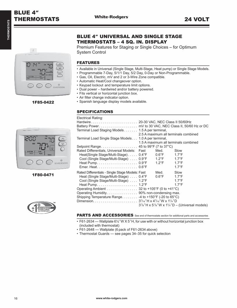
BLUE 4” UNIVERSAL AND SINGLE STAGETHERMOSTATS – 4 SQ. IN. DISPLAYPremium Features for Staging or Single Choices – for Optimum System Control
FEATURES•AvailableinUniversal(SingleStage,Multi-Stage,Heatpump)orSingleStageModels.•Programmable7-Day,5/1/1Day,5/2Day,0-DayorNon-Programmable.•Gas,Oil,Electric,mVand2or3-WireZonecompatible.•AutomaticHeat/Coolchangeoveroption.•Keypadlockout andtemperaturelimitoptions.•Dualpower–hardwiredand/orbatterypowered.•Fitsverticalorhorizontaljunctionbox.•Airfilterchangeindicatoroption.•Spanishlanguagedisplaymodelsavailable.
SPECIFICATIONSElectrical Rating:Hardwire . . . . . . . . . . . . . . . . . . . . . . . . 20-30 VAC, NEC Class II 50/60HzBattery Power. . . . . . . . . . . . . . . . . . . . mV to 30 VAC, NEC Class II, 50/60 Hz or DCTerminal Load Staging Models . . . . . . . 1.5 A per terminal, 2.5 A maximum all terminals combinedTerminal Load Single Stage Models. . . 1.0 A per terminal, 1.5 A maximum all terminals combinedSetpoint Range. . . . . . . . . . . . . . . . . . . 45 to 99°F (7 to 37°C)Rated Differentials, Universal Models: Fast Med. Slow Heat(Single Stage/Multi-Stage) . . . . . 0.4°F 0.6°F 1.7°F Cool (Single Stage/Multi-Stage) . . . . 0.9°F 1.2°F 1.7°F Heat Pump. . . . . . . . . . . . . . . . . . . . . 0.9°F 1.2°F 1.7°F Emer. Heat. . . . . . . . . . . . . . . . . . . . . 0.6°F 1.7°FRated Differentials - Single Stage Models: Fast Med. Slow Heat (Single Stage/Multi-Stage) . . . . 0.4°F 0.6°F 1.7°F Cool (Single Stage/Multi-Stage) . . . . 1.2°F 1.7°F Heat Pump. . . . . . . . . . . . . . . . . . . . . 1.2°F 1.7°FOperating Ambient . . . . . . . . . . . . . . . . 32to+105°F(0to+41°C)Operating Humidity. . . . . . . . . . . . . . . . 90% non-condensing max.Shipping Temperature Range. . . . . . . . -4to+150°F(-20to65°C)Dimension. . . . . . . . . . . . . . . . . . . . . . . 37/16”H x 47/16”W x 11/4”D 37/8”H x 51/8”W x 11/4”D – (Universal models)
PARTS AND ACCESSORIES See end of thermostats section for additional parts and accessories
•F61-2634—Wallplate6½”W X 5”H, for use with or without horizontal junction box (included with thermostat)•F61-2648—Wallplate(6packofF61-2634above)•ThermostatGuards—seepages34–35forquickselection
1F85-0422
1F80-0471
www.white-rodgers.com16
24 VOLT

THER
MO
STAT
S
BLUE 4”THERMOSTATS
?PAGES 147–154
TECHNICAL HELP
1F80-0471 / 1F86-0471 ......WiringDiagrams/Configuration...........See page 1471F83-0471 / 1F85-0471 ......Wiring Diagrams .................................See pages 148–1491F83-0422 / 1F85-0422 ......WiringDiagrams/Configuration...........See pages 149–1511F85-0477 ..........................WiringDiagrams/Configuration...........See pages 152–154
www.white-rodgers.com 17
24 VOLT
UNIVERSAL STAGING/HEAT PUMP THERMOSTATS – BLUE 4” THERMOSTATS
SingleStage
Multi-Stage
HeatPump Programs Model Applications
Ther
mos
tat P
ower
Sou
rce*
Selectable Performance Features
Comfort andConvenience
FeaturesTerminals
Stages Heat/Coolby System
Program Options
Periodsper dayOptions
ModelNumber
Gas
/ O
il / E
lect
ric
3 W
ire Z
one
Valv
e
Mill
ivol
t Com
patib
le
Hum
idity
Con
trol
(H)-H
umid
ity /
(D)-D
ehum
idity
Aut
o C
hang
eove
r
Prog
ram
mab
le F
an
Ener
gy M
gt. A
war
e
Key
pad
Lock
out
(T)-T
otal
/(P)-P
artia
lSe
t-Poi
nt T
empe
ratu
re L
imits
Adj
usta
ble
Max
/Min
.In
door
Rem
ote
Sens
ors
Max
. Num
ber +
The
rmos
tat
Ave
rage
and
/or W
eigh
ted
Out
door
Rem
ote
Sens
orD
ispl
ay S
ize
(Squ
are
Inch
es)
Ligh
ted
Dis
play
Coo
l Sav
ings
Mem
ory
Bac
k-U
p(P
)-Per
man
ent /
(B)-B
atte
ry
1/1 2/2 3/2 7,5+1+1,5+2,Ø 4, Ø 1F85-0477
Universal B, H T 4.0 *** P RC, RH, C, W/E, W2,Y, Y2, O/B, G, L, 6
1/1 2/2 2/1 5+1+1,5+2,Ø 4, Ø 1F85-0422
Universal B, H T 4.0 *** P RC, RH, C, W/E,W2,Y,Y2, O/B, G, L, 6
1/1 2/2 2/1 5+1+1,5+2,Ø 4, Ø 1F85ST-0422
Universal** B, H 4.0 *** P RC, RH, C, W/E, W2,Y, Y2, O/B, G, L, 6
1/1 2/2 3/2 Ø Ø 1F83-0471Universal B, H T 4.0 *** P RC, RH, C, W/E, W2,Y,
Y2, O/B, G, L, 6
1/1 2/2 2/1 Ø Ø 1F83-0422Universal B, H T 4.0 *** P RC, RH, C, W/E, W2,Y,
Y2, O/B, G, L, 6
** ST model is Spanish language display
SINGLE STAGE THERMOSTATS – BLUE 4” THERMOSTATS
SingleStage
Multi-Stage
HeatPump Programs Model Applications
Ther
mos
tat P
ower
Sou
rce*
Selectable Performance Features
Comfort andConvenience
FeaturesTerminals
Stages Heat/Coolby System
Program Options
Periodsper dayOptions
ModelNumber
Gas
/ O
il / E
lect
ric
3 W
ire Z
one
Valv
e
Mill
ivol
t Com
patib
le
Hum
idity
Con
trol
(H)-H
umid
ity /
(D)-D
ehum
idity
Aut
o C
hang
eove
r
Prog
ram
mab
le F
an
Ener
gy M
gt. A
war
e
Key
pad
Lock
out
(T)-T
otal
/(P)-P
artia
lSe
t-Poi
nt T
empe
ratu
re L
imits
Adj
usta
ble
Max
/Min
.In
door
Rem
ote
Sens
ors
Max
. Num
ber +
The
rmos
tat
Ave
rage
and
/or W
eigh
ted
Out
door
Rem
ote
Sens
orD
ispl
ay S
ize
(Squ
are
Inch
es)
Ligh
ted
Dis
play
Coo
l Sav
ings
Mem
ory
Bac
k-U
p(P
)-Per
man
ent /
(B)-B
atte
ry
1/1 1/1 5+1+1,5+2,Ø 4, Ø 1F80-0471 B, H 4.0 *** P RC, RH, C, W, Y,
O/B, G
1/1 1/1 5+1+1,5+2,Ø 4, Ø 1F80ST-0471** B, H 4.0 *** P RC, RH, C, W, Y,
O/B, G
1/1 1/1 Ø Ø 1F86-0471 B, H 4.0 *** P RC, RH, C, W, Y, O/B, G
1/1 1/1 Ø Ø 1F86ST-0471** B, H 4.0 *** P RC, RH, C, W, Y, O/B, G
* H = Hardwired (Requires Common) ** ST models are Spanish language display B, H = Battery Powered or Hardwired *** Optional Continuous Display Light w/ Hardwire connection B = Battery Assist Powered
THER
MO
STAT
S
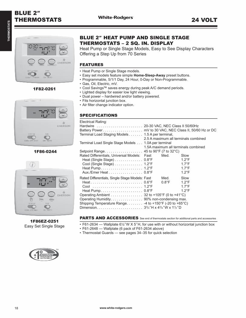
BLUE 2”THERMOSTATS
1F82-0261
1F86-0244
1F86EZ-0251Easy Set Single Stage
BLUE 2” HEAT PUMP AND SINGLE STAGE THERMOSTATS – 2 SQ. IN. DISPLAYHeat Pump or Single Stage Models, Easy to See Display Characters Offering a Step Up from 70 Series
FEATURES•HeatPumporSingleStagemodels.•EasysetmodelsfeaturesimpleHome-Sleep-Away preset buttons. •Programmable,5/1/1Day,24Hour,0-DayorNon-Programmable.•Gas,Oil,Electric,mV.•CoolSavings™savesenergyduringpeakA/Cdemandperiods. •Lighteddisplayforeasierlowlightviewing.•Dualpower–hardwiredand/orbatterypowered.•Fitshorizontaljunctionbox.•Airfilterchangeindicatoroption.
SPECIFICATIONSElectrical Rating: Hardwire . . . . . . . . . . . . . . . . . . . . . . . 20-30 VAC, NEC Class II 50/60Hz Battery Power. . . . . . . . . . . . . . . . . . . . mV to 30 VAC, NEC Class II, 50/60 Hz or DC Terminal Load Staging Models . . . . . . . 1.5 A per terminal, 2.5 A maximum all terminals combinedTerminal Load Single Stage Models . . . 1.0A per terminal 1.5A maximum all terminals combined Setpoint Range. . . . . . . . . . . . . . . . . . . 45 to 90°F (7 to 32°C)Rated Differentials, Universal Models: Fast Med. Slow Heat (Single Stage) . . . . . . . . . . . . . . 0.8°F 1.2°F Cool (Single Stage) . . . . . . . . . . . . . . 1.2°F 1.7°F Heat Pump. . . . . . . . . . . . . . . . . . . . . 1.2°F 1.7°F Aux./Emer Heat . . . . . . . . . . . . . . . . . 0.8°F 1.2°FRated Differentials, Single Stage Models: Fast Med. Slow Heat . . . . . . . . . . . . . . . . . . . . . . . . . . 0.6°F 0.8°F 1.2°F Cool . . . . . . . . . . . . . . . . . . . . . . . . . 1.2°F 1.7°F Heat Pump. . . . . . . . . . . . . . . . . . . . . 0.8°F 1.2°FOperating Ambient . . . . . . . . . . . . . . . . 32to+105°F(0to+41°C)Operating Humidity. . . . . . . . . . . . . . . . 90% non-condensing max.Shipping Temperature Range. . . . . . . . -4to+150°F(-20to+65°C)Dimension. . . . . . . . . . . . . . . . . . . . . . . 33/4”H x 43/4”W x 11/2”D
PARTS AND ACCESSORIES See end of thermostats section for additional parts and accessories
•F61-2634—Wallplate6½”W X 5”H, for use with or without horizontal junction box •F61-2648—Wallplate(6packofF61-2634above)•ThermostatGuards—seepages34–35forquickselection
www.white-rodgers.com18
24 VOLT

THER
MO
STAT
S
HEAT PUMP THERMOSTATS – BLUE 2” THERMOSTATS
SingleStage
Multi-Stage
HeatPump Programs Model Applications
Ther
mos
tat P
ower
Sou
rce*
Selectable Performance Features
Comfort and Convenience
Features Terminals
Stages Heat/Coolby System
Program Options
Periods Per Day Options
ModelNumber
Gas
/ O
il / E
lect
ric
3 W
ire Z
one
Valv
e
Mill
ivol
t Com
patib
le
Hum
idity
Con
trol
(H)-H
umid
ity /
(D)-D
ehum
idify
Aut
o C
hang
eove
r
Prog
ram
mab
le F
an
Ener
gy M
gt. R
ecov
ery
Key
pad
Lock
out
(T)-T
otal
/ (P
)-Par
tial
Set-P
oint
Tem
pera
ture
Lim
itsA
djus
tabl
e M
ax/M
inIn
door
Rem
ote
Sens
ors
Max
. Num
ber +
The
rmos
tat
Aver
age
and/
or W
eigh
ted
Out
door
Rem
ote
Sens
or
Dis
play
Siz
e(S
quar
e in
ches
)
Ligh
ted
Dis
play
Mem
ory
Bac
k-U
p(P
)-Per
man
ent /
(B)-B
atte
ry
2/1 5+1+1 4 1F82-0261 3 3 B, H 3 2.0 3*** P R,C,W2,Y,O/B,G,L2/1 Easy Set
Non-Programmable –Home-Sleep-Away
1F89EZ-0251 3 3 B, H 2.0 3*** P R,C,W2,Y,O/B,G,L
2/1 Ø Ø 1F89-0211 3 3 B, H 2.0 3*** P R,C,W2,Y,O/B,G,L
BLUE 2”THERMOSTATS
?
SINGLE STAGE THERMOSTATS – BLUE 2” THERMOSTATS
SingleStage
Multi-Stage
HeatPump Programs Model Applications
Ther
mos
tat P
ower
Sou
rce*
Selectable Performance Features
Comfort and Convenience
Features Terminals
Stages Heat/Coolby System
Program Options
Periods Per Day Options
ModelNumber
Gas
/ O
il / E
lect
ric
3 W
ire Z
one
Valv
e
Mill
ivol
t Com
patib
le
Hum
idity
Con
trol
(H)-H
umid
ity /
(D)-D
ehum
idify
Aut
o C
hang
eove
r
Prog
ram
mab
le F
an
Ener
gy M
gt. R
ecov
ery
Key
pad
Lock
out
(T)-T
otal
/ (P
)-Par
tial
Set-P
oint
Tem
pera
ture
Lim
itsA
djus
tabl
e M
ax/M
inIn
door
Rem
ote
Sens
ors
Max
. Num
ber +
The
rmos
tat
Aver
age
and/
or W
eigh
ted
Out
door
Rem
ote
Sens
or
Dis
play
Siz
e(S
quar
e in
ches
)
Ligh
ted
Dis
play
Mem
ory
Bac
k-U
p(P
)-Per
man
ent /
(B)-B
atte
ry
1/1 1/1 5+1+1 4 1F80-0261 3 3 B, H 3 2.0 3*** P R,C,W,Y,O/B,G1/1 1/1 24 Hours 4 1F80-0224 3 3 B, H 3 2.0 3*** P R,C,W,Y,O/B,G1/1 1/1 Easy Set
Non-Programmable –Home-Sleep-Away
1F86EZ-0251 3 3 B, H 2.0 3*** P R,C,W,Y,O/B,G
1/1 1/1 Ø Ø 1F86-0244 3 3 B, H 2.0 3*** P R,C,W,Y,O/B,G
* H = Hardwired (Requires Common) B = Battery Powered B, H = Battery Powered or Hardwired *** Optional Continuous Display Light w/ Hardwire connection
PAGES 155–158
TECHNICAL HELP
1F80-0224 / 1F80-0261 / 1F86-0244 / 1F87-0261 ..... WiringDiagrams/Configuration ...........See pages 155–1561F82-0261 / 1F89-0211 .....WiringDiagrams/Configuration ...........See pages 157–158
www.white-rodgers.com 19
24 VOLT

THER
MO
STAT
S
CLASSIC 80 SERIESTHERMOSTATS
1F85-277
1F80-361
1F86-344
CLASSIC 80 SERIES UNIVERSAL / HEAT PUMPAND SINGLE STAGE THERMOSTATSResidential and Light Commercial – Single Stage, Multi-Stage and HeatPumpApplications.Classic80SeriesThermostatsarePackedwith Premium Features
FEATURES•Choice of battery powered, dual power or hardwired models. •Fossil fuel or electric heat compatible. •LargeLCDwithbacklight.•Permanent program retention during power loss. •Configurationmenuallowskeypadselectionofoptions.•Selectable Celsius or Fahrenheit temperature display. •Selectable Energy Management Recovery (1F85-277 / 1F80-361 / 1F87-361 / 1F82-261).
SPECIFICATIONSElectrical Rating Single Stage: Dual Power or Battery Power Model . . mV to 30 VAC, NEC Class II, 50/60 Hz or DC Input-Hardwire Model . . . . . . . . . . . . . 20 to 30 VACElectrical Rating Staging . . . . . . . . . . . 20 to 30 VAC, NEC Class IITerminal Load. . . . . . . . . . . . . . . . . . . . 1.0 A per terminal, 1.5 A maximum all terminals combinedSetpoint Range. . . . . . . . . . . . . . . . . . . 45 to 90°F (7 to 32°C)Rated Differential (Single Stage) . . . . . Heat 0.6° or 1.5°F Cool 1.2°F Rated Differential (Multi-Stage) . . . . . . Heat 0.6° or 1.5°F Cool 1.2°F Rated Differential (Heat Pump) . . . . . . Heat & Cool 0.75° or 1.2°F Operating Ambient . . . . . . . . . . . . . . . . 32to+105°F(0to+41°C)Operating Humidity. . . . . . . . . . . . . . . . 90% non-condensing max.Shipping Temperature Range. . . . . . . . -4to+150°F(-20to+65°C)Dimensions Thermostat . . . . . . . . . . . . 37/8”H x 6”W x 13/16”D
PARTS AND ACCESSORIES See end of thermostats section for additional parts and accessories
•F61-2500—Wallplate45/8”H x 75/8”Wforall1F80’s(exceptBlue) Includes adapter plate for mounting to horizontal or vertical junction box •ThermostatGuards—seepages34–35
24 VOLT
www.white-rodgers.com20

THER
MO
STAT
S
UNIVERSAL STAGING/HEAT PUMP THERMOSTATS – CLASSIC 80 SERIES THERMOSTATS
SingleStage
Multi-Stage
HeatPump Programs Model Applications
Ther
mos
tat P
ower
Sou
rce*
Selectable Performance Features
Comfort and Convenience
Features Terminals
Stages Heat/Coolby System
Program Options
Periods Per Day Options
ModelNumber
Gas
/ O
il / E
lect
ric
3 W
ire Z
one
Valv
e
Mill
ivol
t Com
patib
le
Hum
idity
Con
trol
(H)-H
umid
ity /
(D)-D
ehum
idify
Aut
o C
hang
eove
r
Prog
ram
mab
le F
an
Ener
gy M
gt. R
ecov
ery
Key
pad
Lock
out
(T)-T
otal
/ (P
)-Par
tial
Set-P
oint
Tem
pera
ture
Lim
itsA
djus
tabl
e M
ax/M
inIn
door
Rem
ote
Sens
ors
Max
. Num
ber +
The
rmos
tat
Aver
age
and/
or W
eigh
ted
Out
door
Rem
ote
Sens
or
Dis
play
Siz
e(S
quar
e in
ches
)
Ligh
ted
Dis
play
Coo
l Sav
ings
Mem
ory
Bac
k-U
p(P
)-Per
man
ent /
(B)-B
atte
ry
1/1 2/2 3/2 7,5+1+1Ø
4, 2, Ø 1F85-277Universal
3 3 B, H 3 3 T 3 2.2 3*** P R,C,E/W1,W2,Y1,Y2,O/B,G,L
2/1 5+1+1 4 1F82-261Heat Pump
H 3 1.8 3*** P R,C,W2,E,Y,O/B,G, L
2/1 Ø Ø 1F89-0211Heat Pump
H 1.8 3*** P R,C,W2,E,Y,O/B,G, L
SINGLE STAGE THERMOSTATS – CLASSIC 80 SERIES THERMOSTATS
SingleStage
Multi-Stage
HeatPump Programs Model Applications
Ther
mos
tat P
ower
Sou
rce*
Selectable Performance Features
Comfort and Convenience
Features Terminals
Stages Heat/Coolby System
Program Options
Periods Per Day Options
ModelNumber
Gas
/ O
il / E
lect
ric
3 W
ire Z
one
Valv
e
Mill
ivol
t Com
patib
le
Hum
idity
Con
trol
(H)-H
umid
ity /
(D)-D
ehum
idify
Aut
o C
hang
eove
r
Prog
ram
mab
le F
an
Ener
gy M
gt. R
ecov
ery
Key
pad
Lock
out
(T)-T
otal
/ (P
)-Par
tial
Set-P
oint
Tem
pera
ture
Lim
itsA
djus
tabl
e M
ax/M
inIn
door
Rem
ote
Sens
ors
Max
. Num
ber +
The
rmos
tat
Aver
age
and/
or W
eigh
ted
Out
door
Rem
ote
Sens
or
Dis
play
Siz
e(S
quar
e in
ches
)
Ligh
ted
Dis
play
Coo
l Sav
ings
Mem
ory
Bac
k-U
p(P
)-Per
man
ent /
(B)-B
atte
ry
1/1 1/1 7-day 4 1F87-361 3 3 B, H 3 2.2 3 P RC,RH,C,W,Y,O,B, G
1/1 1/1 5+1+1 4 1F80-361 3 3 B, H 3 2.2 3 P RC,RH,C,W,Y,O,B, G
1/1 1/1 Ø Ø 1F86-344 3 3 B, H 2.2 3 P RC,RH,C,W,Y,O,B, G
CLASSIC 80 SERIESTHERMOSTATS
?
24 VOLT
* H = Hardwired (Requires Common) Heat Pump for Stage 1, and Gas / Oil / Electric for 2nd stage / Emergency B, H = Battery Powered or Hardwired *** Optional Continuous Display Light w/ Hardwire connection B = Battery Powered
PAGES 159–161
TECHNICAL HELP
1F80-224 -240, -241, -361 / 1F86-241, -344 / 1F87-361...WiringDiagrams/Configuration .........See page 1591F82-261 / 1F89-211 ............WiringDiagrams/Configuration .........See page 1601F85-277 ..............................WiringDiagrams/Configuration .........See page 161
www.white-rodgers.com 21

THER
MO
STAT
S
www.white-rodgers.com22
70 SERIESTHERMOSTATS
1F72-151
1F78-151
1E78-151
1E78-144
70 SERIES HEAT PUMP – SINGLE STAGE THERMOSTATSResidential Single Stage and Heat Pump Applications. 70 Series are the Perfect Upgrade from Mechanical Thermostats. CoversWallMarksLeftbyMostMechanicalThermostatstheNeed for an Extra Wall Plate
FEATURES•Fossilfuelorelectriccompatible.•LargeLCDwithbacklight.•SelectableCelsiusorFahrenheittemperaturedisplay.• IncludesB/Oterminals.•Electronicaccuracy.
SPECIFICATIONSElectrical Rating: Hardwire . . . . . . . . . . . . . . . . . . . . . . . . . 20 to 30 VAC, NEC Class II, 50/60 Hz Batterry Power . . . . . . . . . . . . . . . . . . . . 20 to 30 VAC, NEC Class IITerminal Load. . . . . . . . . . . . . . . . . . . . . 1.0 A per terminal, 1.5 A maximum all terminals combinedSetpoint Range. . . . . . . . . . . . . . . . . . . . 45 to 90°F (7 to 32°C)Rated Differentials - Single Stage Models: Fast Slow Heat (Single Stage) . . . . . . . . . . . . . . . 0.8°F 1.5°F Cool (Single Stage) Fixed . . . . . . . . . . 1.2°F Heat Pump . . . . . . . . . . . . . . . . . . . . . 1.2°F 1.5°F Aux./Emer. Heat. . . . . . . . . . . . . . . . . . 0.8°F 1.2°F Operating Ambient . . . . . . . . . . . . . . . . . 32to+105°F(0to+41°C)Operating Humidity. . . . . . . . . . . . . . . . . 90% non-condensing max.Shipping Temperature Range. . . . . . . . . -4 to+150°F(-20to65°C)Dimensions. . . . . . . . . . . . . . . . . . . . . . . 313/16”H x 51/8”W x 11/8”D – (1F78) 55/16”H x 33/16”W x 11/8”D – (1E78)
PARTS AND ACCESSORIES See end of thermostats section for additional parts and accessories
•F61-2510—Wallplatefor1Fmodelswithadaptorforhorizontalor vertical junction box 61/2”W x 41/2”H•F61-2593—Wallplatefor1D70,1E70modelswithadaptorforhorizontalor vertical junction box 41/2”W x 619/32”H•ThermostatGuards—seepages34–35
24 VOLT
THER
MO
STAT
S
www.white-rodgers.com 23
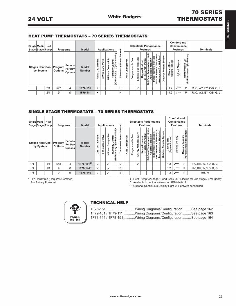
HEAT PUMP THERMOSTATS – 70 SERIES THERMOSTATS
SingleStage
Multi-Stage
HeatPump Programs Model Applications
Ther
mos
tat P
ower
Sou
rce*
Selectable Performance Features
Comfort and Convenience
Features Terminals
Stages Heat/Coolby System
Program Options
Periods Per Day Options
ModelNumber
Gas
/ O
il / E
lect
ric
3 W
ire Z
one
Valv
e
Mill
ivol
t Com
patib
le
Hum
idity
Con
trol
(H)-H
umid
ity /
(D)-D
ehum
idify
Aut
o C
hang
eove
r
Prog
ram
mab
le F
an
Ener
gy M
gt. R
ecov
ery
Key
pad
Lock
out
(T)-T
otal
/ (P
)-Par
tial
Set-P
oint
Tem
pera
ture
Lim
itsA
djus
tabl
e M
ax/M
inIn
door
Rem
ote
Sens
ors
Max
. Num
ber +
The
rmos
tat
Aver
age
and/
or W
eigh
ted
Out
door
Rem
ote
Sens
or
Dis
play
Siz
e(S
quar
e in
ches
)
Ligh
ted
Dis
play
Mem
ory
Bac
k-U
p(P
)-Per
man
ent /
(B)-B
atte
ry
2/1 5+2 4 1F72-151 H 3 1.2 3*** P R,C,W2,EY,O/B,G,L2/1 Ø Ø 1F79-111 H 1.2 3*** P R,C,W2,EY,O/B,G,L
SINGLE STAGE THERMOSTATS – 70 SERIES THERMOSTATS
SingleStage
Multi-Stage
HeatPump Programs Model Applications
Ther
mos
tat P
ower
Sou
rce*
Selectable Performance Features
Comfort and Convenience
Features Terminals
Stages Heat/Coolby System
Program Options
Periods Per Day Options
ModelNumber
Gas
/ O
il / E
lect
ric
3 W
ire Z
one
Valv
e
Mill
ivol
t Com
patib
le
Hum
idity
Con
trol
(H)-H
umid
ity /
(D)-D
ehum
idify
Aut
o C
hang
eove
r
Prog
ram
mab
le F
an
Ener
gy M
gt. R
ecov
ery
Key
pad
Lock
out
(T)-T
otal
/ (P
)-Par
tial
Set-P
oint
Tem
pera
ture
Lim
itsA
djus
tabl
e M
ax/M
inIn
door
Rem
ote
Sens
ors
Max
. Num
ber +
The
rmos
tat
Aver
age
and/
or W
eigh
ted
Out
door
Rem
ote
Sens
or
Dis
play
Siz
e(S
quar
e in
ches
)
Ligh
ted
Dis
play
Mem
ory
Bac
k-U
p(P
)-Per
man
ent /
(B)-B
atte
ry
1/1 1/1 5+2 4 1F78-151 3 3 B 3 1.2 3*** P RC,RH,W,Y,O,B,G1/1 1/1 Ø Ø 1F78-144 3 3 B 1.2 3*** P RC,RH,W,Y,O,B,G1/1 Ø Ø 1E78-140 3 3 B 1.2 3*** P RH, W
70 SERIESTHERMOSTATS
?
* H = Hardwired (Requires Common) Heat Pump for Stage 1, and Gas / Oil / Electric for 2nd stage / Emergency B = Battery Powered Available in vertical style order 1E78-144/151 *** Optional Continuous Display Light w/ Hardwire connection
PAGES 162–164
TECHNICAL HELP
1E78-151 ..............................WiringDiagrams/Configuration .........See page 1621F72-151 / 1F79-111 ............WiringDiagrams/Configuration .........See page 1631F78-144 / 1F78-151 ............WiringDiagrams/Configuration .........See page 164
24 VOLT

THER
MO
STAT
S
MECHANICAL THERMOSTATS
1E30N-910
1F56N-444
1F56N-361
?PAGE 165
MECHANICAL THERMOSTATS – MERCURY FREEReplaces Hundreds of White-Rodgers and Competitive Models. Enclosed Snap Action Contacts for Reliable, Economical and Environmentally Friendly Control
FEATURES
•Mercuryfreesnap-actioncontactswithdustcover.•Resistanttovibration.•Mountstowallorjunctionbox.•Builtinbimetalthermometer.•ClassicWhitecolor.•HorizontalandVerticalmodels.•24Volt,750mVand3-wirezoneoptions.Seetablebelow.
SPECIFICATIONSElectrical Rating . . . . . . . . . . . . . . . . . . 20-30 VAC, NEC Class II 50/60HzHeating . . . . . . . . . . . . . . . . . . . . . . . . . 0.15 to 1.2 AmpsCooling . . . . . . . . . . . . . . . . . . . . . . . . . 0.15 to 1.2 AmpsHeat Anticipator . . . . . . . . . . . . . . . . . . Adjustable from 0.15 to 1.2 AmpsCool Anticipator . . . . . . . . . . . . . . . . . . FixedDifferential Heat . . . . . . . . . . . . . . . . . . 1°FDifferential Cool . . . . . . . . . . . . . . . . . . 1.5°F Setpoint Range. . . . . . . . . . . . . . . . . . . 50°F to 90°F (10°C to 32°C)Operating Humidity Range . . . . . . . . . . 0-90% non-condensing Dimensions. . . . . . . . . . . . . . . . . . . . . . 41/2”H x 23/4”W x 11/2”D – 1E (Vertical) 41/2”H x 31/4”W x 15/8”D – 1E with Heat / Cool Subbase 23/4”H 41/2”W x 11/2”D – 1F (Horizontal) 31/4”H x 41/2”W x 15/8”D – 1F with Heat / Cool Subbase
PARTS AND ACCESSORIES See end of thermostats section for additional parts and accessories
•F61-2301—Wallplate55/8”W x 53/4”H with adapter plate to horizontal or vertical junction box•ThermostatGuards—seepages34–35
TECHNICAL HELP
Configuration/Wiring . . . . . . . . . . . . . . . . . . . See page 165
ModelNumber
Orie
ntat
ion
Vert
ical
, Hor
izon
tal
Applications Options
Control Range Terminals
Hea
t Onl
y
Coo
l Onl
y
Hea
t-Coo
l
Con
vent
iona
l Gas
/ O
il / E
lect
ric
Elec
tric
Str
ip H
eat
Hea
t Pum
p (N
o A
ux.)
3-W
ire Z
one
Valv
e
Mill
ivol
t Com
patib
le
Incl
udes
Opt
iona
l F92
-056
3 K
it fo
r Tem
pera
ture
Loc
king
or
Lim
iting
Incl
udes
Sw
itche
d Su
bbas
e H
eat-O
ff-C
ool &
Fan
Aut
o-O
n
Incl
udes
Sw
itche
d Su
bbas
eH
eat-O
ff
Incl
udes
Wal
lpla
te H
eat O
nly
(No
Syst
em o
r Off
Switc
h)
Incl
udes
Wal
lpla
te
Coo
l Onl
y or
3-W
ire Z
one
(No
Syst
em o
r Off
Switc
h)
1E30N-910 V 3 3 3 3 50 to 90°F R, W1E50N-301 V 3 3 3 3 3 3 3 3 3 3 3 3 3 50 to 90°F R, W1E56N-444 V 3 3 3 3 3 3 3 3 3 3 3 50 to 90°F RC,RH,W,Y,O,B,G,A1F56N-444 H 3 3 3 3 50 to 90°F RC,RH,W,Y,O,B,G,A
1E30N-311 V 3 3 3 3 50 to 90°F / 10 to 32°C R, W
1E50N-303 V 3 3 3 3 3 3 50 to 90°F / 10 to 32°C R, W
1E56N-361 V 3 3 3 3 3 3 3 3 3 3 3 50 to 90°F / 10 to 32°C RC,RH,W,Y,O,B,G,A
1F56N-361 V 3 3 3 3 3 3 3 3 3 3 3 50 to 90°F / 10 to 32°C RC,RH,W,Y,O,B,G,A
Indicates Canadian Model Number: call 1-800-305-6953 to order
24 VOLT
www.white-rodgers.com24

THER
MO
STAT
S
1C26-101
1C20-101
MECHANICAL THERMOSTATS
?PAGE165
ECONOMY MECHANICAL THERMOSTATS – MERCURY-FREEReliable Performance in an Attractive Design
FEATURES
•Ruggedsnap-actioncontacts.•Adjustableheatanticipator.•Bi-Metalthermometer.•Heat/Coolmodelincludesswitchingsubbase.•Heat/CoolmodelcompatiblewithElectricHeatsystems.
SPECIFICATIONS
Anticipation Rating, Heating . . . . . Adjustable from 0.15 to 1.2 AmpsAnticipation Rating, Cooling . . . . . FixedDifferential, Heating . . . . . . . . . . . 2°F (1.1°C)Differential, Cooling . . . . . . . . . . . 4°F (2.2°C)Dimensions. . . . . . . . . . . . . . . . . . 33/4”H x 27/8”W x 11/2”DDimensions, Switching Models. . . 33/4”H x 31/8”W x 15/8”DElectrical Rating . . . . . . . . . . . . . . mV to 30V, 50/60 Hz or DC
PARTS AND ACCESSORIES See end of thermostats section for additional parts and accessories
•WallplateF61-2499—51/8”H x 5”W•ThermostatGuards—seepages34–35
TECHNICAL HELP
Configuration/Wiring . . . . . . . . . . . . . . . . . . . See page 165
ModelNumber
TypicalApplication
StagesHeat / Cool
SystemSwitch
FanSwitch Contacts
AnticipationHeat / Cool Range Shape Terminals
1C20-101 Heat Only ➂ 1 None ➀ None Snap-Action Adjustable 50-90°F (10-32°C) Vertical R, W1C20-102 Heat Only 1 None None Snap-Action Adjustable 50-90°F (10-32°C) Vertical R, W1C21-101 Cool Only 1 None None Snap-Action Fixed 50-90°F (10-32°C) Vertical R,Y1C26-101 Heat / Cool ➁
➂
1 / 1 Heat-Off-Cool Auto-On Snap-Action Adjustable / Fixed 50-90°F (10-32°C) Vertical RC, RH, W,Y,O,B,G,A
➀ Lowesttemperaturesettingis“OFF”position➁ Includesoptional“A”terminalconnectionforElectricHeatsystemsthatrequirethethermostattoenergizetheBlower(Gterminal)onacallforheat➂ IncludesF61-2499wallmountingplatetocovermarksleftbypreviousthermostat
24 VOLT
www.white-rodgers.com 25

THER
MO
STAT
S
INSTANTEXPERT
LINE VOLTAGE THERMOSTATSQUICK SELECTION GUIDE
HE
AT
ING
RangeMax.
RangeMin.
DifferentialMax.
DifferentialMin. Model Element
CapillaryLength
SwitchAction
PageNumber
80°F 40°F 2°F 2°F 1G65-641 ThermostatSnap Action
Open onRise
28
80°F 40°F 2°F 2°F 1G66-641 ThermostatSnap Action
Open onRise
28
85°F 40°F 1°F 1°F 1A65-641 HydraulicKnob
Open onRise
28
85°F 40°F 1°F 1°F 1A65W-641 HydraulicKnob
Open onRise
28
85°F 40°F 1°F 1°F 1A66-641 HydraulicKnob
Open onRise
28
85°F 40°F 1°F 1°F 1A66W-641 HydraulicKnob
Open onRise
28
85°F 55°F 2°F 2°F 152-9 Thermostat Open onRise
32
95°F 55°F 2°F 2°F 152-10 Thermostat Open onRise
32
CO
OL
ING 90°F 20°F 20°F 3°F 201-8 Self
ContainedClose on
Rise31
HE
AT
& C
OO
L
90°F 36°F 1.5°F 1.5°F 1A10-651 HydraulicKnob
SPDT 29
90°F 36°F 1.5°F 1.5°F 1A11-2 HydraulicKnob
SPDT 30
90°F 36°F 1.5°F 1.5°F 1A16-51 HydraulicKnob
SPDT 29
95°F 55°F 3°F 3°F 179-1 Thermostat SPDT 31
U.S. Models only
www.white-rodgers.com26

THER
MO
STAT
S
1E65-144
LINE VOLTAGE DIGITAL THERMOSTAT
Model Number Programmable Range Differential Switch Action
Display Back Light Load
1E65-144
45o to 90oF(7oC to 32oC)
0.5˚C Open on Rise 3 2.0A, 120VAC, 250W2.0A, 240VAC, 500W16.7A, 120VAC, 2000W16.7A, 240VAC, 4000W
1E65-151BL
3 3˚to30˚C NormalMode:0.05˚CFanMode:0.5˚C
Open on Rise 3 1.25A, 120VAC, 150W1.25A, 240VAC, 300W12.5A, 120VAC, 1500W12.5A, 240VAC, 3000W
1E65-151
3 3˚to30˚C NormalMode:0.05˚CFanMode:0.5˚C
Open on Rise 1.25A, 120VAC, 150W1.25A, 240VAC, 300W12.5A, 120VAC, 1500W12.5A, 240VAC, 3000W
1E65-140BL
3˚to30˚C NormalMode:0.05˚CFanMode:0.5˚C
Open on Rise 3 1.25A, 120VAC, 150W1.25A, 240VAC, 300W12.5A, 120VAC, 1500W12.5A, 240VAC, 3000W
1E65-140
3˚to30˚C NormalMode:0.05˚CFanMode:0.5˚C
Open on Rise 1.25A, 120VAC, 150W1.25A, 240VAC, 300W12.5A, 120VAC, 1500W12.5A, 240VAC, 3000W
Features and Benefi tsHoneywell
RLV310AubeTH109
CMACIT3000
WR1E65
Backlight 3
Menu-Driven Options 3 3
Large Display 3
Large Characters 3
Power @ 240 VAC 3 KW 3 KW 3 KW 4 KWConsumption Indicator 20% 20% 10% 10%Selectable Anticipation 3
Adjustable Temperature Display +3oCTemperature Resolution 0.5oC 0.5oC 1oC 0.1oCWarranty (yrs) 3 3 1 5
?PAGE 166
LINE VOLTAGE DIGITAL THERMOSTATLine Voltage Digital Thermostats for Applications Covering 150W Up to 4000W. Choice of Programmable or Non-programmable Models. For Electric Baseboard, Convectors and Fan-Forced Heater Applications. 1E65-144 will Also Cover Radiant Floor and Ceiling
FEATURES
•LargeLCDwithgreatcontrastforgreaterviewing.•100%silentoperationwithoptionalproportionalcontrolfeature.•Selectableanticipationforultimateperformance.•CelsiusofFahrenheitcompatible.•Whitecolor.•Doesnotcontainmercury.
SPECIFICATIONS
Display Resolution . . . . . . . . . . . . . . . . . . . . . . 1oF (0.1oC) Approval . . . . . . . . . . . . . . . . . . . . . . . . . . . . . . C.S.A. approved
PARTS AND ACCESSORIES See end of thermostats section for additional parts and accessories
•F61-2642–Adapterplateforuniversalmounting.
TECHNICAL HELP
Configuration/WiringDiagram . . . . . . . . . . . . . . See page 166
Indicates Canadian Model Number: call 1-800-305-6953 to order
www.white-rodgers.com 27
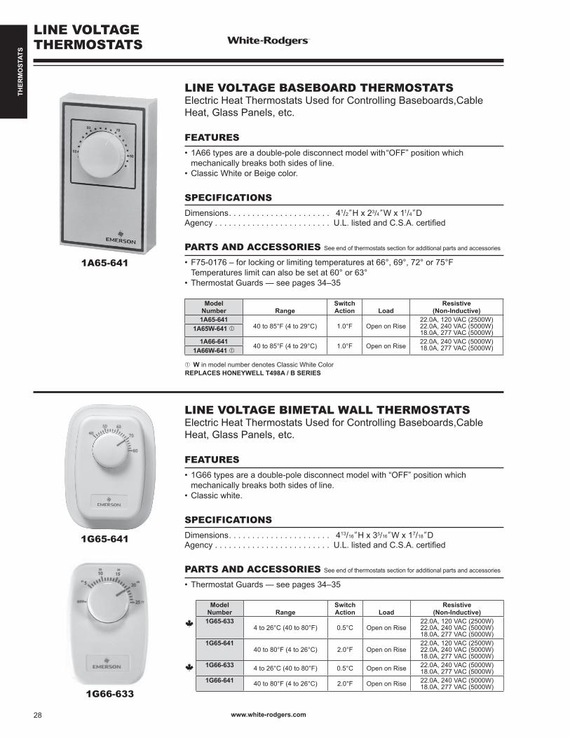
THER
MO
STAT
S
LINE VOLTAGE THERMOSTATS
1A65-641
1G65-641
1G66-633
LINE VOLTAGE BASEBOARD THERMOSTATSElectric Heat Thermostats Used for Controlling Baseboards,Cable Heat, Glass Panels, etc.
FEATURES
•1A66typesareadouble-poledisconnectmodelwith“OFF”positionwhich mechanicallybreaksbothsidesofline.•ClassicWhiteorBeigecolor.
SPECIFICATIONS
Dimensions. . . . . . . . . . . . . . . . . . . . . . 41/2”H x 23/4”W x 11/4”DAgency . . . . . . . . . . . . . . . . . . . . . . . . . U.L.listedandC.S.A.certified
PARTS AND ACCESSORIES See end of thermostats section for additional parts and accessories
•F75-0176–forlockingorlimitingtemperaturesat66°, 69°, 72° or 75°F Temperatures limit can also be set at 60° or 63°•ThermostatGuards—seepages34–35
LINE VOLTAGE BIMETAL WALL THERMOSTATSElectric Heat Thermostats Used for Controlling Baseboards,Cable Heat, Glass Panels, etc.
FEATURES
•1G66typesareadouble-poledisconnectmodelwith“OFF”positionwhich mechanicallybreaksbothsidesofline.•Classicwhite.
SPECIFICATIONS
Dimensions. . . . . . . . . . . . . . . . . . . . . . 413/16”H x 35/16”W x 17/18”DAgency . . . . . . . . . . . . . . . . . . . . . . . . . U.L.listedandC.S.A.certified
PARTS AND ACCESSORIES See end of thermostats section for additional parts and accessories
•ThermostatGuards—seepages34–35
ModelNumber Range
Switch Action Load
Resistive(Non-Inductive)
1A65-64140 to 85°F (4 to 29°C) 1.0°F Open on Rise
22.0A, 120 VAC (2500W) 22.0A, 240 VAC (5000W)18.0A, 277 VAC (5000W)1A65W-641
1A66-64140 to 85°F (4 to 29°C) 1.0°F Open on Rise
22.0A, 240 VAC (5000W) 18.0A, 277 VAC (5000W)1A66W-641
➀ W in model number denotes Classic White ColorREPLACES HONEYWELL T498A / B SERIES
ModelNumber Range
Switch Action Load
Resistive(Non-Inductive)
1G65-6334 to 26°C (40 to 80°F) 0.5°C Open on Rise
22.0A, 120 VAC (2500W) 22.0A, 240 VAC (5000W)18.0A, 277 VAC (5000W)
1G65-64140 to 80°F (4 to 26°C) 2.0°F Open on Rise
22.0A, 120 VAC (2500W) 22.0A, 240 VAC (5000W)18.0A, 277 VAC (5000W)
1G66-633 4 to 26°C (40 to 80°F) 0.5°C Open on Rise 22.0A, 240 VAC (5000W) 18.0A, 277 VAC (5000W)
1G66-641 40 to 80°F (4 to 26°C) 2.0°F Open on Rise 22.0A, 240 VAC (5000W) 18.0A, 277 VAC (5000W)
www.white-rodgers.com28
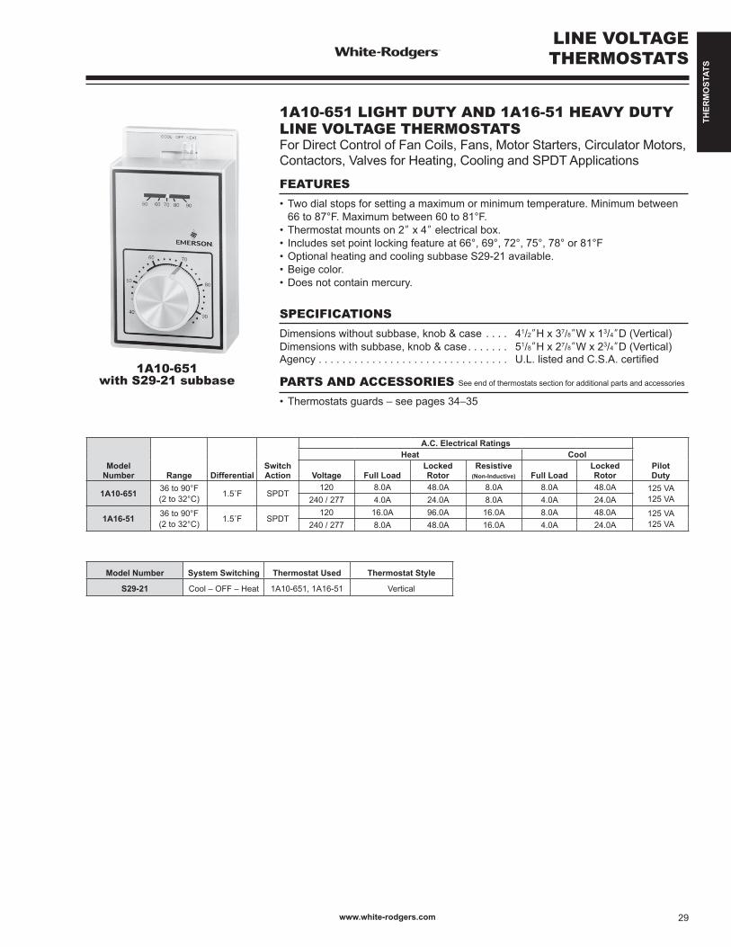
THER
MO
STAT
S
LINE VOLTAGE THERMOSTATS
1A10-651with S29-21 subbase
1A10-651 LIGHT DUTY AND 1A16-51 HEAVY DUTYLINE VOLTAGE THERMOSTATSFor Direct Control of Fan Coils, Fans, Motor Starters, Circulator Motors, Contactors, Valves for Heating, Cooling and SPDT Applications
FEATURES
•Twodialstopsforsettingamaximumorminimumtemperature.Minimumbetween 66 to 87°F. Maximum between 60 to 81°F.•Thermostatmountson2” x 4” electrical box.• Includessetpointlockingfeatureat66°,69°,72°,75°,78°or81°F•OptionalheatingandcoolingsubbaseS29-21available.•Beigecolor.•Doesnotcontainmercury.
SPECIFICATIONS
Dimensionswithoutsubbase,knob&case . . . . 41/2”H x 37/8”W x 13/4”D (Vertical)Dimensionswithsubbase,knob&case . . . . . . . 51/8”H x 27/8”W x 23/4”D (Vertical)Agency . . . . . . . . . . . . . . . . . . . . . . . . . . . . . . . . U.L.listedandC.S.A.certified
PARTS AND ACCESSORIES See end of thermostats section for additional parts and accessories
•Thermostatsguards–seepages34–35
ModelNumber Range Differential
Switch Action
A.C. Electrical Ratings
Pilot Duty
Heat Cool
Voltage Full LoadLocked Rotor
Resistive(Non-Inductive) Full Load
Locked Rotor
1A10-651 36 to 90°F(2 to 32°C) 1.5˚F SPDT
120 8.0A 48.0A 8.0A 8.0A 48.0A 125 VA125 VA240 / 277 4.0A 24.0A 8.0A 4.0A 24.0A
1A16-51 36 to 90°F(2 to 32°C) 1.5˚F SPDT
120 16.0A 96.0A 16.0A 8.0A 48.0A 125 VA125 VA240 / 277 8.0A 48.0A 16.0A 4.0A 24.0A
Model Number System Switching Thermostat Used Thermostat Style
S29-21 Cool – OFF – Heat 1A10-651, 1A16-51 Vertical
www.white-rodgers.com 29

THER
MO
STAT
S
LINE VOLTAGE THERMOSTATS
1A11-2
1A11-2 LIGHT DUTY FAN COIL THERMOSTATFor Direct Control of Line Voltage Valves and/or Blower Motors on Fan Coil Units Featuring Manual Changeover from Heat to Cool and a 3-Speed Fan Switch, Subbase Included
FEATURES
•Mountstoastandardverticaloutletboxoronatwo-gangoutletbox.Mayalsobe mounted on a 4”x 4” junction box with an adapter (not provided).•Wiring colorcodedforeaseofinstallation.•3-speedmanualfanswitch:High–Medium–Low.•SystemSwitch:Heat–OFF–Cool.“OFF”breaksbothvalveandfancircuits.•Beigecolor.
SPECIFICATIONS
Dimensions. . . . . . . . . . . . . . . . . . . . . . 41/2”H x 41/2”W x 21/4”DAgency . . . . . . . . . . . . . . . . . . . . . . . . . U.L. listed and C.S.A. approved
PARTS AND ACCESSORIES See end of thermostats section for additional parts and accessories
•ThermostatGuards—seepages34–35
Model Number Range Differential
SwitchAction
Contact Ratings Pilot DutyMotor Ratings (inductive) Full Load Motor Ratings (inductive) Locked Rotor 120/240
1A11-2 36 to 90°F(2 to 32°C) 1.5˚F SPDT
120 VAC 240 VAC 277 VAC 120 VAC 240 VAC 277 VAC 277 VAC5.5A 2.75A 2.3A 33.0A 16.5A 13.8A 120A
TA
N
BLU
E
COOL
COOL
HEAT
HEAT
VALVE(SOL)
L1*(HOT) GNDHIGH
HIGH
FANSWITCH
SYSTEMSWITCH
MED
FAN
MED
OFF
LOW
LOW
RE
D
BLUE
RED
OR
AN
GE
BLA
CK
GR
EE
N
1A11-25-wire with ground, for single valve,
manual heat/cool changeover
CUSTOMERCONNECTIONS
Note: Above FAN and SYSTEM switches shown inMED and HEAT positions respectively .
THERMOSTATSCHEMATIC
*L1 is Power In
– Thermostat cycles both fan and valve
– Thermostat cycles fan only (if valve is not used tape orange lead)
–System"OFF"breaksbothvalveandfancircuits
– Thermostat cycles valve only with continuous fan (interchange valve and L1 leads)
www.white-rodgers.com30

THER
MO
STAT
S
LINE VOLTAGE THERMOSTATS
201-8
179-1
HEAVY DUTY SPACE THERMOSTATS FOR COOLINGDesigned for Use in Garages, Factories, Warehouses and Similar Commercial and Industrial Installations
FEATURES
•Dust,moistureandverminresistantheavymetalcase.•Nolevelingrequired–Mountsinanyposition.•Quickresponsetotemperaturechanges.•Nickelplatedelement.•Extraruggedswitchmechanism.
SPECIFICATIONS
Dimensions. . . . . . . . . . . . . . . . . . . . . . . . . . . . . 53/8”H x 21/2”W x 25/16”D (Vertical)Finish . . . . . . . . . . . . . . . . . . . . . . . . . . . . . . . . . Grey ColorAgency . . . . . . . . . . . . . . . . . . . . . . . . . . . . . . . . U.L. listed and C.S.A. approved
LINE VOLTAGE THERMOSTAT FOR HEATING / COOLINGControl Suitable for Fans or Water Solenoids on Heating / Cooling Convectors or Any Similar Application that Requires a Heavy Duty Room Thermostat with Single Pole, Double Throw (SPDT) Switch Action
FEATURES
•Canhandlemanycoolinginstallationswithoutuseofrelayormotorstarter.•Heavygaugesteelcase–Mountsonvertical2” x 4”boxorflustowall.•Hydraulicactionelement–Unaffectedbymotion–Nolevelingrequired.•Dustproofcase.
SPECIFICATIONS
Dimensions. . . . . . . . . . . . . . . . . . . . . . . . . . . . . 6”H x 23/4”W x 21/2”D Finish . . . . . . . . . . . . . . . . . . . . . . . . . . . . . . . . . Grey ColorAgency . . . . . . . . . . . . . . . . . . . . . . . . . . . . . . . . U.L. listed and C.S.A. approved
PARTS AND ACCESSORIES See end of thermostats section for additional parts and accessories
•ThermostatGuards—seepages34–35
Model Number Range Differential System Action
Full Electrical Rating
Bulb Size
CapillaryLength
Motor Rating(Full Load)
Resistive(Non-Inductive)
120 VAC 240 VAC 120 VAC 240 VAC
201-820 to 90°F(-7 to 32°C)
Adj. 3 to 20°F(2 to 11°C) Close on Rise
FGHSee page 222 16.0A 8.0A 5.6A 2.8A 25.0A 22.0A
Model Number Range Differential Action
Full Electrical Rating
Motor Rating(Full Load)
120 VAC 240 VAC
179-155 to 95°F
(13 to 35°C)Fixed 3.0°F
(1.6°C)SPDT
(Heat / Cool)SPDT
See page 222 7.4A 3.7
www.white-rodgers.com 31
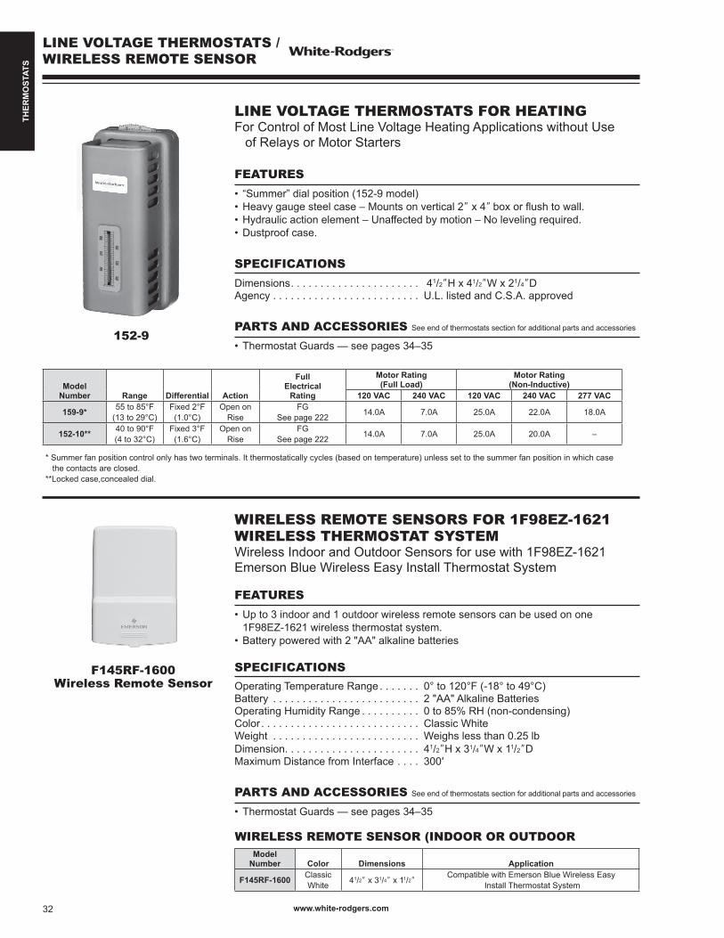
THER
MO
STAT
S
LINE VOLTAGE THERMOSTATS /WIRELESS REMOTE SENSOR
152-9
F145RF-1600Wireless Remote Sensor
LINE VOLTAGE THERMOSTATS FOR HEATINGFor Control of Most Line Voltage Heating Applications without Use of Relays or Motor Starters
FEATURES
• “Summer”dialposition(152-9model)•Heavygaugesteelcase–Mountsonvertical2” x 4” boxorflushtowall.•Hydraulicactionelement–Unaffectedbymotion–Nolevelingrequired.•Dustproofcase.
SPECIFICATIONS
Dimensions. . . . . . . . . . . . . . . . . . . . . . 41/2”H x 41/2”W x 21/4”DAgency . . . . . . . . . . . . . . . . . . . . . . . . . U.L. listed and C.S.A. approved
PARTS AND ACCESSORIES See end of thermostats section for additional parts and accessories
•ThermostatGuards—seepages34–35
WIRELESS REMOTE SENSORS FOR 1F98EZ-1621 WIRELESS THERMOSTAT SYSTEMWireless Indoor and Outdoor Sensors for use with 1F98EZ-1621 Emerson Blue Wireless Easy Install Thermostat System
FEATURES
•Upto3indoorand1outdoorwirelessremotesensorscanbeusedonone 1F98EZ-1621 wireless thermostat system.•Batterypoweredwith2"AA"alkalinebatteries
SPECIFICATIONSOperating Temperature Range . . . . . . . 0° to 120°F (-18° to 49°C)Battery . . . . . . . . . . . . . . . . . . . . . . . . . 2"AA"AlkalineBatteriesOperating Humidity Range . . . . . . . . . . 0 to 85% RH (non-condensing)Color . . . . . . . . . . . . . . . . . . . . . . . . . . . Classic WhiteWeight . . . . . . . . . . . . . . . . . . . . . . . . . Weighs less than 0.25 lbDimension. . . . . . . . . . . . . . . . . . . . . . . 41/2”H x 31/4”W x 11/2”DMaximum Distance from Interface . . . . 300′
PARTS AND ACCESSORIES See end of thermostats section for additional parts and accessories
•ThermostatGuards—seepages34–35
ModelNumber Range Differential Action
Full Electrical
Rating
Motor Rating(Full Load)
Motor Rating(Non-Inductive)
120 VAC 240 VAC 120 VAC 240 VAC 277 VAC
159-9* 55 to 85°F(13 to 29°C)
Fixed 2°F(1.0°C)
Open on Rise
FGSee page 222 14.0A 7.0A 25.0A 22.0A 18.0A
152-10** 40 to 90°F(4 to 32°C)
Fixed 3°F(1.6°C)
Open on Rise
FGSee page 222 14.0A 7.0A 25.0A 20.0A –
* Summer fan position control only has two terminals. It thermostatically cycles (based on temperature) unless set to the summer fan position in which case the contacts are closed.**Lockedcase,concealeddial.
WIRELESS REMOTE SENSOR (INDOOR OR OUTDOORModel
Number Color Dimensions Application
F145RF-1600 Classic White 41/2” x 31/4” x 11/2”
Compatible with Emerson Blue Wireless Easy Install Thermostat System
www.white-rodgers.com32
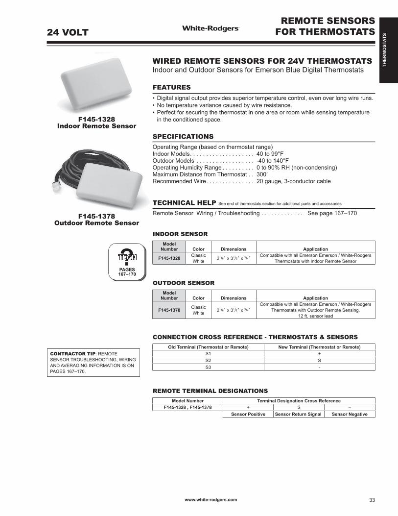
THER
MO
STAT
S
F145-1328Indoor Remote Sensor
REMOTE SENSORSFOR THERMOSTATS
F145-1378Outdoor Remote Sensor
?PAGES167–170
CONTRACTOR TIP: REMOTE SENSOR TROUBLESHOOTING, WIRING AND AVERAGING INFORMATION IS ON PAGES 167–170.
24 VOLT
INDOOR SENSOR
ModelNumber Color Dimensions Application
F145-1328 Classic White 21/8” x 31/2” x 3/4”
Compatible with all Emerson Emerson / White-Rodgers Thermostats with Indoor Remote Sensor
OUTDOOR SENSOR
ModelNumber Color Dimensions Application
F145-1378 Classic White 21/8” x 31/2” x 3/4”
Compatible with all Emerson Emerson / White-Rodgers Thermostats with Outdoor Remote Sensing.
12 ft. sensor lead
CONNECTION CROSS REFERENCE - THERMOSTATS & SENSORS
Old Terminal (Thermostat or Remote) New Terminal (Thermostat or Remote)S1 +S2 SS3 -
REMOTE TERMINAL DESIGNATIONS
Model Number Terminal Designation Cross ReferenceF145-1328 , F145-1378 + S –
Sensor Positive Sensor Return Signal Sensor Negative
WIRED REMOTE SENSORS FOR 24V THERMOSTATSIndoor and Outdoor Sensors for Emerson Blue Digital Thermostats
FEATURES
•Digitalsignaloutputprovidessuperiortemperaturecontrol,evenoverlongwireruns.•Notemperaturevariancecausedbywireresistance.•Perfectforsecuringthethermostatinoneareaorroomwhilesensingtemperature in the conditioned space.
SPECIFICATIONSOperating Range (based on thermostat range)Indoor Models. . . . . . . . . . . . . . . . . . . . 40 to 99°FOutdoor Models . . . . . . . . . . . . . . . . . . -40 to 140°FOperating Humidity Range . . . . . . . . . . 0 to 90% RH (non-condensing)Maximum Distance from Thermostat . . 300′Recommended Wire. . . . . . . . . . . . . . . 20 gauge, 3-conductor cable
TECHNICAL HELP See end of thermostats section for additional parts and accessories
Remote Sensor Wiring / Troubleshooting . . . . . . . . . . . . . See page 167–170
www.white-rodgers.com 33
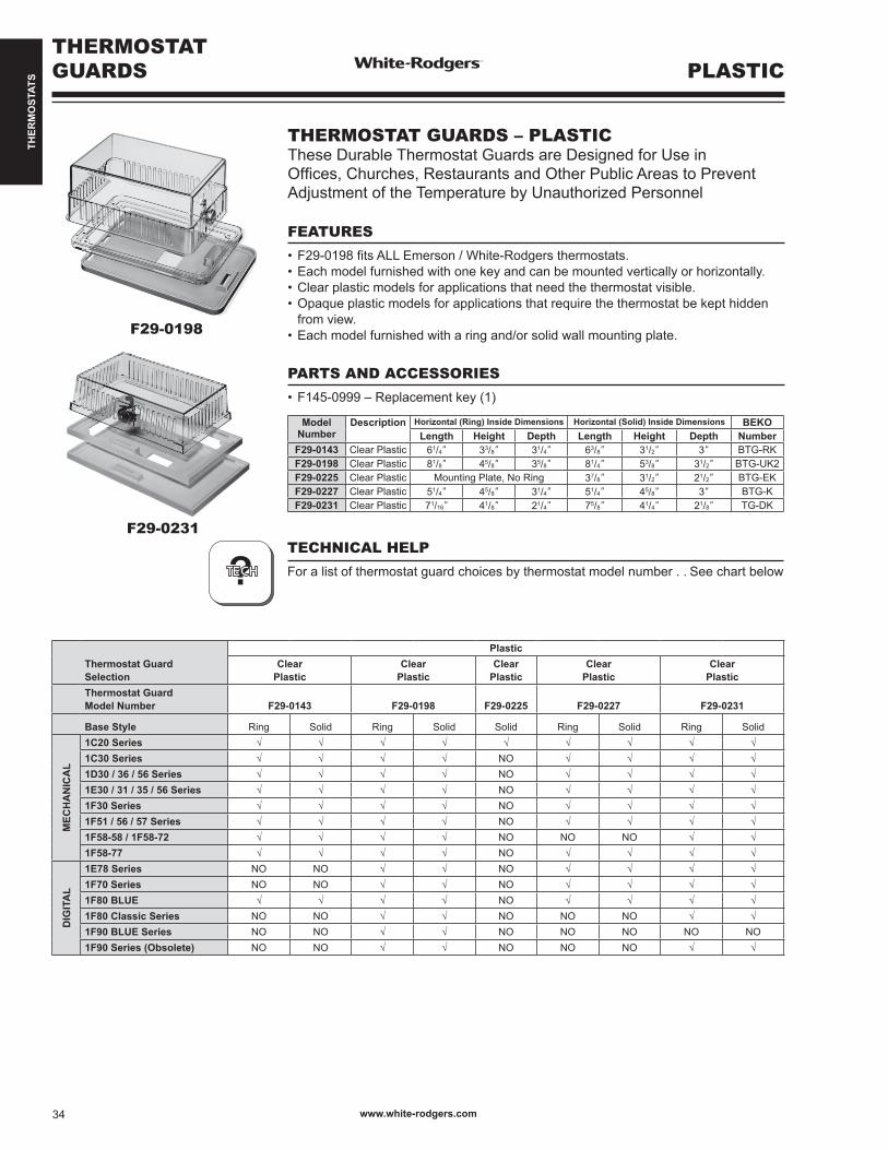
THER
MO
STAT
S
F29-0198
F29-0231
THERMOSTATGUARDS PLASTIC
ModelNumber
Description Horizontal (Ring) Inside Dimensions Horizontal (Solid) Inside Dimensions BEKOLength Height Depth Length Height Depth Number
F29-0143 Clear Plastic 61/4” 33/8” 31/4” 63/8” 31/2” 3” BTG-RKF29-0198 Clear Plastic 81/8” 45/8” 35/8” 81/4” 53/8” 31/2” BTG-UK2F29-0225 Clear Plastic Mounting Plate, No Ring 37/8” 31/2” 21/2” BTG-EKF29-0227 Clear Plastic 51/4” 45/8” 31/4” 51/4” 45/8” 3” BTG-KF29-0231 Clear Plastic 71/16” 41/8” 21/4” 75/8” 41/4” 21/8” TG-DK
THERMOSTAT GUARDS – PLASTICThese Durable Thermostat Guards are Designed for Use inOffices,Churches,RestaurantsandOtherPublicAreastoPreventAdjustment of the Temperature by Unauthorized Personnel
FEATURES
•F29-0198fitsALLEmerson/White-Rodgersthermostats.•Eachmodelfurnishedwithonekeyandcanbemountedverticallyorhorizontally.•Clearplasticmodelsforapplicationsthatneedthethermostatvisible.•Opaqueplasticmodelsforapplicationsthatrequirethethermostatbekepthidden from view.•Eachmodelfurnishedwitharingand/orsolidwallmountingplate.
PARTS AND ACCESSORIES
•F145-0999–Replacementkey(1)
Thermostat GuardSelection
PlasticClear
PlasticClear
PlasticClear
PlasticClear
PlasticClear
PlasticThermostat GuardModel Number F29-0143 F29-0198 F29-0225 F29-0227 F29-0231
Base Style Ring Solid Ring Solid Solid Ring Solid Ring Solid
MEC
HA
NIC
AL
1C20 Series √ √ √ √ √ √ √ √ √1C30 Series √ √ √ √ NO √ √ √ √1D30 / 36 / 56 Series √ √ √ √ NO √ √ √ √1E30 / 31 / 35 / 56 Series √ √ √ √ NO √ √ √ √1F30 Series √ √ √ √ NO √ √ √ √1F51 / 56 / 57 Series √ √ √ √ NO √ √ √ √1F58-58 / 1F58-72 √ √ √ √ NO NO NO √ √1F58-77 √ √ √ √ NO √ √ √ √
DIG
ITA
L
1E78 Series NO NO √ √ NO √ √ √ √1F70 Series NO NO √ √ NO √ √ √ √1F80 BLUE √ √ √ √ NO √ √ √ √1F80 Classic Series NO NO √ √ NO NO NO √ √1F90 BLUE Series NO NO √ √ NO NO NO NO NO1F90 Series (Obsolete) NO NO √ √ NO NO NO √ √
TECHNICAL HELP
For a list of thermostat guard choices by thermostat model number . . See chart below?
www.white-rodgers.com34
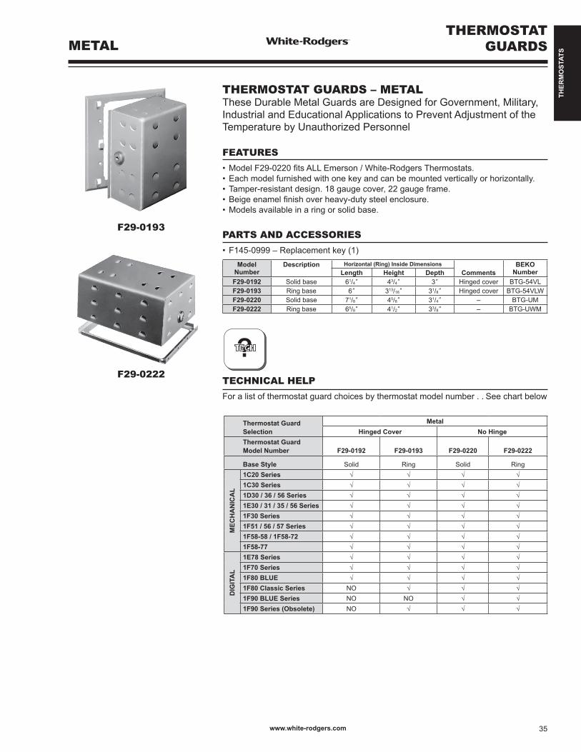
THER
MO
STAT
S
F29-0193
F29-0222
THERMOSTATGUARDSMETAL
?
ModelNumber
Description Horizontal (Ring) Inside DimensionsComments
BEKONumberLength Height Depth
F29-0192 Solid base 61/4” 43/4” 3” Hinged cover BTG-54VLF29-0193 Ring base 6” 313/16” 31/8” Hinged cover BTG-54VLWF29-0220 Solid base 71/8” 45/8” 31/4” – BTG-UMF29-0222 Ring base 65/8” 41/2” 33/8” – BTG-UWM
THERMOSTAT GUARDS – METALThese Durable Metal Guards are Designed for Government, Military, Industrial and Educational Applications to Prevent Adjustment of the Temperature by Unauthorized Personnel
FEATURES
•ModelF29-0220fitsALLEmerson/White-RodgersThermostats.•Eachmodelfurnishedwithonekeyandcanbemountedverticallyorhorizontally.•Tamper-resistantdesign.18gaugecover,22gaugeframe.•Beigeenamelfinishoverheavy-dutysteelenclosure.•Modelsavailableinaringorsolidbase.
PARTS AND ACCESSORIES
•F145-0999–Replacementkey(1)
TECHNICAL HELP
For a list of thermostat guard choices by thermostat model number . . See chart below
Thermostat GuardSelection
MetalHinged Cover No Hinge
Thermostat GuardModel Number F29-0192 F29-0193 F29-0220 F29-0222
Base Style Solid Ring Solid Ring
MEC
HA
NIC
AL
1C20 Series √ √ √ √1C30 Series √ √ √ √1D30 / 36 / 56 Series √ √ √ √1E30 / 31 / 35 / 56 Series √ √ √ √1F30 Series √ √ √ √1F51 / 56 / 57 Series √ √ √ √1F58-58 / 1F58-72 √ √ √ √1F58-77 √ √ √ √
DIG
ITA
L
1E78 Series √ √ √ √1F70 Series √ √ √ √1F80 BLUE √ √ √ √1F80 Classic Series NO √ √ √1F90 BLUE Series NO NO √ √1F90 Series (Obsolete) NO √ √ √
www.white-rodgers.com 35

THER
MO
STAT
S
PARTS ANDACCESSORIES THERMOSTATS
THERMOSTAT ACCESSORIES Item
NumberModel
Number Description
F16-8101 Cover assembly for 1F78-151 programmable.
F61-2301 Wallplate for low voltage standard thermostats (55/8”H x 53/4”W). Beige. Includes adapter for mounting to vertical junction box.Same as F61-2068 except white.
F61-2300 Wallplate for all 1F90 series thermostats (except Blue models), (71/4”W x 51/2”H), Classic White color, includes adapter plate for mounting to horizontal or vertical junction box.
F61-2499 Wallplate for 1C20-xxx/1C26-xxx (55/8”H x 5”W)
F61-2500 Wallplate for all 1F80 series thermostats (except Blue models),(75/8”W x 43/4”H), Classic Whitecolor, includes adapter plate formounting to horizontal or verticaljunction box.
F61-2510 Wallplate for all 1F70 series thermo-stats, 61/2”W x 41/2”H, Classic White color, Includes adapter plate for mounting to horizontal or verticaljunction box.
F61-2550 Wallplate for all 1F70 series thermo-stats, 61/2”W x 41/2”H, Classic White color, does not Include adapter plate for mounting to horizontal or verticaljunction box.
F61-2593 Wallplate for 1D70 or 1E70 series thermostats, 41/2”W x 619/32”H, Classic White color.
F61-2600 Wallplate for 90 series Blue Touch-screen thermostats, 81/8”W x 53/8”H, Classic White color, for use with orwithout horizontal junction box.
F61-2634 Wallplate for 90 and 80 series Blue thermostats, 61/2”W x 5”H, Classic White color, for use with or without horizontal junction box.
F61-2663 Wallplate for Sensi Wi-Fi Thermostat, white, 63/4”W x 41/2”H for use with or without horizontal junction box
ItemNumber
ModelNumber Description
F75-0176 Temperatureknoblockingorlimitingkitfor1A65-641,1A65W-641,1A66-641 and 1A66W-641.
F92-0563 Temperatureleverlockingortemperaturelimitingkitforlowvoltage thermostats except 1C70, 1C20 and 1E26 series.
F145-1082 Replacement door 1F90/1F97 (-51, -60, -71) 1F91-71, 1F92-71, 1F94-71, 1F95-71.
F145-0999 Replacementkeyforallthermostatguards, F29 series.
F145-1328 90 Series Wired Indoor Remote Sensor. Replaces all previous Indoor Remote Sensors.
F145-1378 90 Series Wired Outdoor Temperature Sensor, For Models with Outdoor Sensor Option.
F61-2648 SameasF61-2634except6pack.
F61-2642 Universal adapter plate for 1E65-144
F145RF-1600
Wireless remote sensor for 1F98EZ-1621
www.white-rodgers.com36
Top Related