


Languages
Pages
Legal

11100 • Unity Automotive
Volkswagen: 99-05 Jetta - 99-06 Golf - 98-10 Beetle - 99-06 Golf GTI - 02-06 Golf GLI Front End Complete Strut Assembly
11100Complete Strut Assembly Installation Instructions
When servicing any vehicle be sure to follow all safety procedures.
First, make sure that when lifting the vehicle that you are using the appropriate jack for the weight of the vehicle.
Make sure before going underneath any vehicle that it is properly supported with sturdy jack stands and on level ground so that the vehicle doesn’t fall or slide off of the jack and onto you.
As with any automotive repair, make sure you have the appropriate tools to do the job so you don’t damage any parts on the vehicle. There is a list of tools needed included in these instructions.
Safety glasses and mechanic gloves should also be worn for your protection.
Be sure to follow the instructions in the order that they are given. The instructions are in a certain order for a reason and improper installation could lead to damage to your vehicle or the parts. Keep in mind that if you damage the parts during installation you will be responsible for the replacement parts.
General Precautions
These complete strut assemblies have been designed and extensively tested to provide the same ridequality and height as the O.E.M. system. Please note that the car will sit approximately 1/2” - 3/4” immediately following installation. This is normal and the car will settle into its O.E.M. ride height as the coil spring adjusts to the weight of the vehicle. This settle period is approximately 500 miles.
These instructions are not meant to replace a certified mechanic. Please use these instructionsas a reference tool only. If you are uncomfortable with any step within these instructionsplease consult an A.S.E. cerfified mechanic.
Minimum Tools Needed For This Installation
Hand Tools (Sockets/Wrenches)
Jack and Jackstands
Spreader (3424)
T10001 Shock Absorber Set(available from Volkswagen)
Screw Drivers
1. Loosen lug nuts on front wheels
2. Raise vehicle and support with suitable jack stands
3. Remove wheels
4. If your car has brake wear pad indicator - disconnect (1) (Image #1)
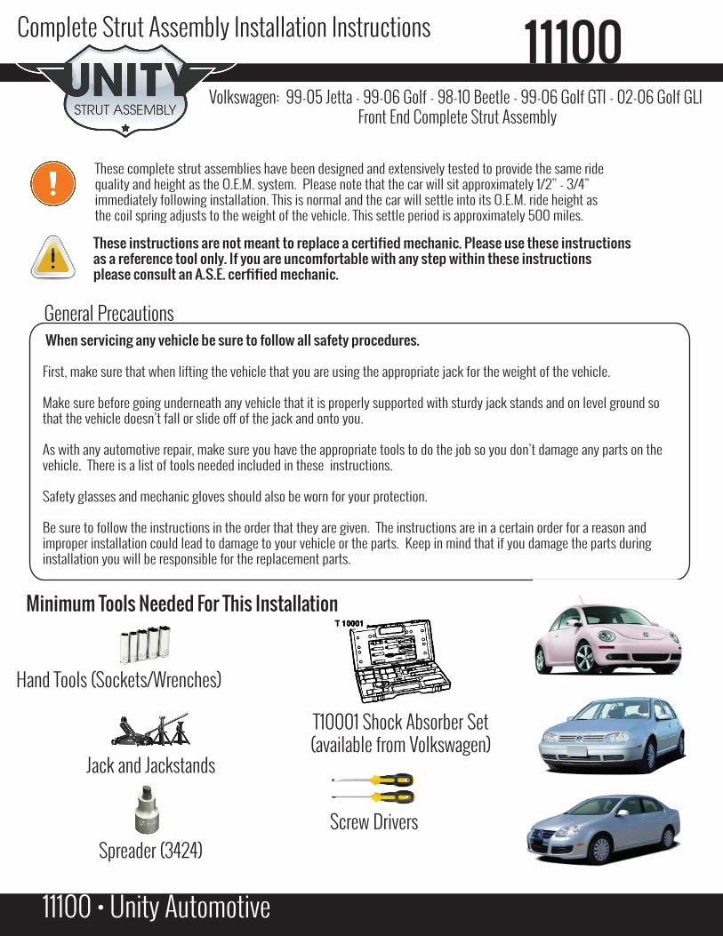
5. Take off heat shield (1) - Push lip - arrow A - with a screwdriver whilewhile pushing at the same time upward (as shown with arrow) (Image #2)
6. If car has brake wear pad indicator, remove bolt B (Image #2)
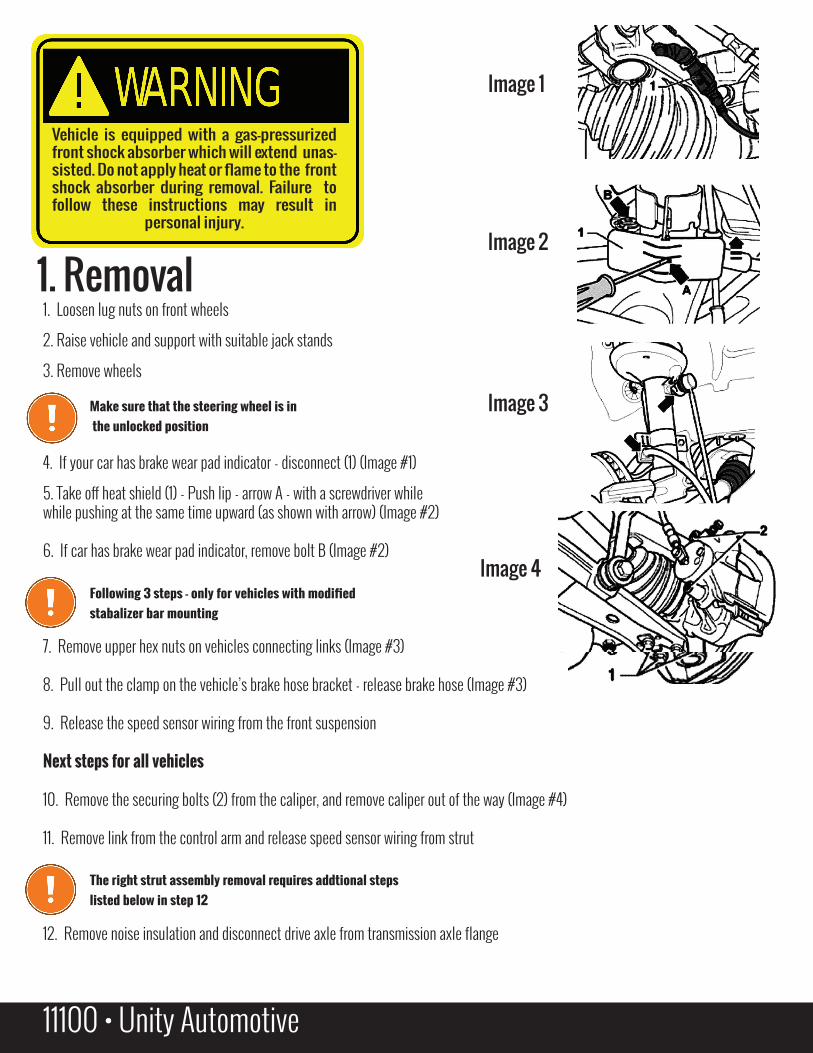
7. Remove upper hex nuts on vehicles connecting links (Image #3)
8. Pull out the clamp on the vehicle’s brake hose bracket - release brake hose (Image #3)
9. Release the speed sensor wiring from the front suspension
Next steps for all vehicles
10. Remove the securing bolts (2) from the caliper, and remove caliper out of the way (Image #4)
11. Remove link from the control arm and release speed sensor wiring from strut
12. Remove noise insulation and disconnect drive axle from transmission axle flange
1. Removal
Vehicle is equipped with a gas-pressurized front shock absorber which will extend unas-sisted. Do not apply heat or flame to the front shock absorber during removal. Failure to follow these instructions may result in
personal injury.
Make sure that the steering wheel is in the unlocked position
11100 • Unity Automotive
Image 1
Image 2
Image 3
Image 4 Following 3 steps - only for vehicles with modified
stabalizer bar mounting
The right strut assembly removal requires addtional stepslisted below in step 12

1. Loosen lug nuts on front wheels
2. Raise vehicle and support with suitable jack stands
3. Remove wheels
4. If your car has brake wear pad indicator - disconnect (1) (Image #1)
5. Take off heat shield (1) - Push lip - arrow A - with a screwdriver whilewhile pushing at the same time upward (as shown with arrow) (Image #2)
6. If car has brake wear pad indicator, remove bolt B (Image #2)
7. Remove upper hex nuts on vehicles connecting links (Image #3)
8. Pull out the clamp on the vehicle’s brake hose bracket - release brake hose (Image #3)
9. Release the speed sensor wiring from the front suspension
Next steps for all vehicles
10. Remove the securing bolts (2) from the caliper, and remove caliper out of the way (Image #4)
11. Remove link from the control arm and release speed sensor wiring from strut
12. Remove noise insulation and disconnect drive axle from transmission axle flange
11100 • Unity Automotive
Following steps is for both sides of the vehicle
13. Seperate wheel bearing housing - suspension strut bolted connector (Image #5)
14. Insert spreader 3242 tool into slot (Image #6)
15. Ratchet handle and pull off spreader 3242.
16. Move the brake disc towards the strut by hand to avoid shock getting caught
in the wheel bearing housing
17. Pull the wheel bearing housing off shock downward
18. Remove the hex nut from top mount using special tool T10001 (Image #7)
19. Remove the strut assembly from the housing
1. Install your new strut assembly
2. Remove the spreader 3424 and tighten the bolt for the wheel bearing
and strut
3. Further installtion is the reverse of the removal
Image 5
Image 6
Image 7
2. Installation
3. Torque specifications 12 point nut for upper spring plate 60 Nm - 44 ft/lbsHex nut for wheel bearing housing 60 Nm - 44 ft/lbs (plus an additional 1/4 turn)
Coupling rod to strut 50 Nm - 36 ft/lbs (plus an additional 1/4 turn)
Top Related