BentleyPublishers.com VW MKIV Golf-Jetta 1.8T EVAP System Servicing

Edition 12.04
Wiring diagram
97-14163
Golf/Jetta No. 91/1
2.0L - Engine - Motronic Multiport Fuel Injection (MFI)/85 kW, code BEV,
from June 2004
Additional Fuse, Relay, Control Module and Connector locations ⇒ Compontent Locations
Troubleshooting Procedures ⇒ Guided Fault Finding using VAS 5051/5052
Relay location on the thirteenfold auxiliary relay panel, aboverelay panel:
Relay panel:
2 J52 - Load Reduction Relay (100)
4 J17 - Fuel Pump (FP) Relay (409)

1 2 3 4 5 6 7 8 9 10 11 12 13 1497-36994
5/31
J593
9
2
T
bl0,5
ro6,0
7/30
ro16,0
500 502
139
ro6,0
A/+
bl0,35
208
T2e/2
4/2
sw16,0
2
S16350A
4
S176110A
5
S177110A
1
S16250A
ro16,0
B
5030
M
ro/sw2,5
A/+
sw35,0
T6/3
226 /8
ro/sw2,5
31a
207 /8
ro/sw2,5
L
G C
C1
B1+
b
DFM
br/ro0,5
TT2e/1
4/1
43
br/ro0,5
D/50b
207 /2
ro/gr2,5
ro/sw1,0
226 /6J JJ J
Edition 12.04
Wiring diagram
ws = whitesw = blackro = redbr = browngn = greenbl = bluegr = grey
ge = yellowor = orange
li = lilac
Golf/Jetta No. 91/2Generator (GEN), starter
A - BatteryB - StarterC - Generator (GEN)C1 - Voltage Regulator (VR)D - Ignition/Starter SwitchJ59 - Load Reduction RelayJ207 - Starting Interlock RelayJ226 - Park/Neutral Position (PNP) RelayS162 - Fuse -1- (30) in fuse bracket/batteryS163 - Fuse -2- (30) in fuse bracket/batteryS176 - Fuse -4- (30) in fuse bracket/batteryS177 - Fuse -5- (30) in fuse bracket/batteryT2e - Double Connector, near starter (vehicles
without air conditioning)T4 - 4-Pin Connector, near starter (vehicles with air
conditioning only)T6 - 6-Pin Connector, brown, in protective housing
for connectors, in plenum chamber, left
500 - Threaded connection -1- (30) on the relay plate
502 - Threaded connection -1- (30a) on the relay plate
- Manual transmission only
- - - Automatic transmission only

15 16 17 18 19 20 21 22 23 24 25 26 27 28
A104
ro6,0
501
A98
D/30
ro2,5
ro6,0
ro2,5
S23720A
37
37a
S22915A
sw1,0
sw1,5
161
A2
sw2,5
29
29a
D/15
186
sw2,5
sw/li1,5
ro/gn1,5
T6/4
97-93800
D78
31a
31a
b
2/87 5/85
271
3/86
sw/li4,0
J
1/30
li0,35
c
ro/gn2,5
c
ro/gr1,5
ro/gn2,5
148
ro6,0
D78
A104
sw/li1,5
T14a/8
56
A32
113
ro1,5
Edition 12.04
Wiring diagram
ws = whitesw = blackro = redbr = browngn = greenbl = bluegr = grey
ge = yellowor = orange
li = lilac
Golf/Jetta No. 91/3Power supply relay
D - Ignition/Starter SwitchJ271 - Motronic engine control module (ECM) power
supply relay, in protective housing, in enginecompartment, left, production control number(428)
S229 - Fuse 29 in fuse holderS237 - Fuse 37 in fuse holderT6 - 6-Pin Connector, brown, in protective housing
for connectors, in plenum chamber, leftT14a - 14-Pin Connector, near battery
501 - Threaded connection -2- (30) on the relay plate
A2 - Plus connection (15), in instrument panel wiringharness
A32 - Plus connection (30), in instrument panel wiringharness
A98 - Plus connection -4- (30), in instrument panelwiring harness
A104 - Plus connection -2- (15), in instrument panelwiring harness
D78 - Plus connection -1- (30a), in enginecompartment wiring harness
- - - Automatic transmission only
97-9380129 30 31 32 33 34 35 36 37 38 39 40 41 42
31a
31a
85
T121/95
li/bl0,35
T121/103
bl/ge0,35
T121/94
li/ro0,35
PQ
T6d/1N70
c
85
T121/102
bl/gn0,35
T6d/2
PQ
T6d/3
PQ
T6d/4
PQ
T6d/5T6d/6
br2,5
J220
N127 N291 N292
D78
T121/62
ro/gn0,35
D78
A104
T121/3
li/sw0,35T6/1
sw/li1,5
A104
T2/1
sw/li4,0
sw/li2,5
Edition 12.04
Wiring diagram
ws = whitesw = blackro = redbr = browngn = greenbl = bluegr = grey
ge = yellowor = orange
li = lilac
Golf/Jetta No. 91/4Motronic engine control module (ECM), ignitionsystem
J220 - Motronic Engine Control Module (ECM), inplenum chamber, center
N70 - Ignition Coil 1 with Power Output StageN127 - Ignition Coil 2 with Power Output StageN291 - Ignition Coil 3 with Power Output StageN292 - Ignition Coil 4 with Power Output StageP - Spark Plug ConnectorsQ - Spark PlugsT2 - 2-Pin Connector, in engine compartment, leftT6 - 6-Pin Connector, brown, in protective housing
for connectors, in plenum chamber, leftT6d - 6-Pin ConnectorT121 - 121-Pin Connector
85 - Ground connection -1-, in engine compartmentwiring harness
A104 - Plus connection -2- (15), in instrument panelwiring harness
D78 - Plus connection -1- (30a), in enginecompartment wiring harness

97-93802
31a
31a
J217T68/3
or/br0,35
T10w/3 T10w/2
or/br0,5
T68/25
or/sw0,5
or/sw0,35
A122
or/br0,35
ws0,5
A121
sw0,5
T121/60T121/58
211 213
or/br0,35
or/sw0,35
85
608
T14a/7br2,5
85
609
135
br4,0
43 44 45 46 47 48 49 50 51 52 53 54 55 56
T121/30
ws/gn0,35
T121/28
br/ro0,5
4
bl/li0,35
T10w/5 T10w/7
189
br0,5
J104
or/sw0,35
J104
can-l can-h
T47a/11T47a/15
J220
J217
T121/21
li0,35
28
T121/47
li/ge0,35
T10w/10
T121/48
ws/ro0,35
T10w/8
Edition 12.04
Wiring diagram
ws = whitesw = blackro = redbr = browngn = greenbl = bluegr = grey
ge = yellowor = orange
li = lilac
Golf/Jetta No. 91/5Motronic engine control module (ECM)
J104 - ABS Control Module (w/EDL), in enginecompartment, left
J217 - Transmission Control Module (TCM)J220 - Motronic Engine Control Module (ECM), in
plenum chamber, centerT10w- 10-Pin Connector, white, in protective housing
for connectors, in plenum chamber, leftT14a - 14-Pin Connector, near batteryT47a - 47-Pin Connector, on ABS Control ModuleT68 - 68-Pin Connector, on Transmission Control
Module (TCM)T121 - 121-Pin Connector
85 - Ground connection -1-, in engine compartmentwiring harness
608 - Ground connection (in center plenum chamber)
609 - Ground connection (in right plenum chamber)
A121 - Connection (high bus), in instrument panelwiring harness
A122 - Connection (low bus), in instrument panelwiring harness
- - - Automatic transmission only
gn/ge0,35
220
12
3
T121/98
T121/86
gn/li0,35
br/bl0,35
31a
31a
T121/108
br/bl0,35
G40
97-93803
220
57 58 59 60 61 62 63 64 65 66 67 68 69 70
T10h/1
T10h/2
T10h/6
T10h/3
T10h/5
gn/ws0,35
gr/ro0,35
ws/bl0,35
ge/gn0,35
gr/bl0,35
T121/72
T121/33
T121/73
T121/35
T121/36
T10h/4
T121/34
T6b/6
br/ws0,35
T6b/1 T6b/5 T6b/2 T6b/4 T6b/3
G185
gr/ws0,5
gr/ro0,5
ws/bl0,5
ge/gn0,5
gr/bl0,5
br/bl1,0
T121/43W
gr/ws0,35
gr/ws0,35
215
T10/1
G79
J220
Edition 12.04
Wiring diagram
ws = whitesw = blackro = redbr = browngn = greenbl = bluegr = grey
ge = yellowor = orange
li = lilac
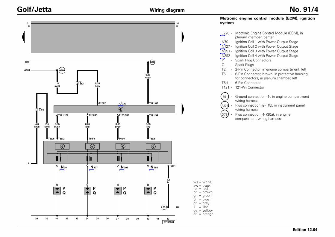
Golf/Jetta No. 91/6Motronic engine control module (ECM), throttleposition (TP) sensor, camshaft position (CMP) sen-sor
G40 - Camshaft Position (CMP) SensorG79 - Throttle Position (TP) SensorG185 - Sender -2- for accelerator pedal positionJ220 - Motronic Engine Control Module (ECM), in
plenum chamber, centerT6b - 6-Pin ConnectorT10 - 10-Pin Connector, orange, in protective housing
for connectors, in plenum chamber, leftT10h - 10-Pin Connector, blue, in protective housing
for connectors, in plenum chamber, leftT121 - 121-Pin Connector
220 - Ground connection (sensor ground), in enginecompartment wiring harness
220
li/ws1,0
T121/118
T6a/5 T6a/3 T6a/2 T6a/1T6a/6
M
T6a/4
li1,0
li/ro0,35
li/ws0,35
li/ge0,35
G186
31a
31a
220
ws0,35
T121/117
T121/83
T121/92
T121/91
71 72 73 74 75 76 77 78 79 80 81 82 83 8497-93804
V144
2 1
M
3
ge/br0,35
gn/li0,35
T10h/7
T10h/9
gn/li0,5
169
bl/ge1,0
li0,5
T14a/4
sw0,5
gn0,35
li0,35
200
3 1
4 2
br/ws0,5
178
G62 G2
T121/84
T121/25
T121/80
T121/93
J220
G187 G188 J338
ge/gn0,5
ge/br0,5
Edition 12.04
Wiring diagram
ws = whitesw = blackro = redbr = browngn = greenbl = bluegr = grey
ge = yellowor = orange
li = lilac
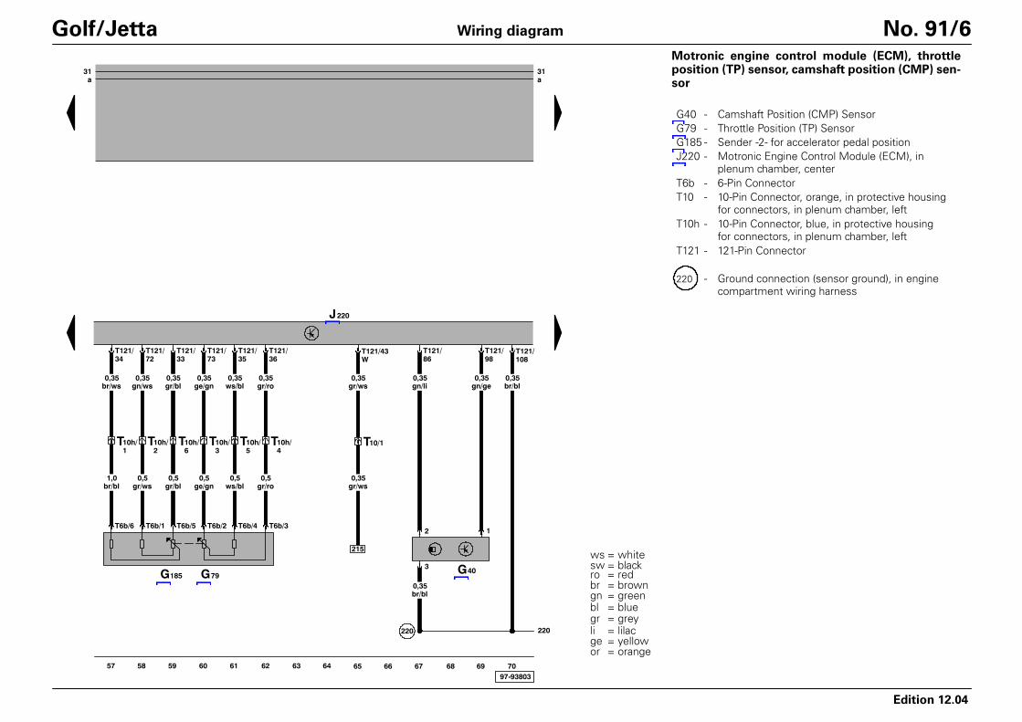
Golf/Jetta No. 91/7Motronic engine control module (ECM), throttlevalve control module, engine coolant temperature(ECT) sensor, leak detection pump (LDP)
G2 - Engine Coolant Temperature (ECT) SensorG62 - Engine Coolant Temperature (ECT) SensorG186 - Throttle drive (power accelerator actuation)G187 - Angle sensor -1- for throttle drive (power
accelerator actuation)G188 - Angle sensor -2- for throttle drive (power
accelerator actuation)J220 - Motronic Engine Control Module (ECM), in
plenum chamber, centerJ338 - Throttle Valve Control ModuleT6a - 6-Pin ConnectorT10h - 10-Pin Connector, blue, in protective housing
for connectors, in plenum chamber, leftT14a - 14-Pin Connector, near batteryT121 - 121-Pin ConnectorV144 - Leak detection pump (LDP)
- Jetta only- Golf only
220
G28
ws0,35
br0,35
T3f/1 T3f/2 T3f/3
sw0,35
T121/41
gn/gr0,35
T121/40
bl/ro0,35
31a
31a
T10/7 T10/8
220
T121/107
G66
gr0,35
bl0,35
T121/82
139
97-9380585 86 87 88 89 90 91 92 93 94 95 96 97 98
J217T68/12
gn0,5
T121/106
G61
gn0,35
sw0,35
ge0,35
T121/99
bl0,35
gn0,35
1 2 2 1
sw0,35
J220 T121/81
gn/ro0,35
T10/2
T121/90
Edition 12.04
Wiring diagram
ws = whitesw = blackro = redbr = browngn = greenbl = bluegr = grey
ge = yellowor = orange
li = lilac
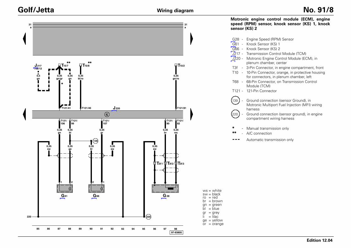
Golf/Jetta No. 91/8Motronic engine control module (ECM), enginespeed (RPM) sensor, knock sensor (KS) 1, knocksensor (KS) 2
G28 - Engine Speed (RPM) SensorG61 - Knock Sensor (KS) 1G66 - Knock Sensor (KS) 2J217 - Transmission Control Module (TCM)J220 - Motronic Engine Control Module (ECM), in
plenum chamber, centerT3f - 3-Pin Connector, in engine compartment, frontT10 - 10-Pin Connector, orange, in protective housing
for connectors, in plenum chamber, leftT68 - 68-Pin Connector, on Transmission Control
Module (TCM)T121 - 121-Pin Connector
139 - Ground connection (sensor Ground), inMotronic Multiport Fuel Injection (MFI) wiringharness
220 - Ground connection (sensor ground), in enginecompartment wiring harness
- Manual transmission only- A/C connection
- - - Automatic transmission only
31a
31a
li0,35
li/gn0,35
li/ro0,35
li/bl0,35
ro/li1,0
ro/li1,0
ro/li1,0
ro/li1,0
T121/88T121/96 T121/97T121/89
T14a/5
D95
ro/li1,0
97-3700199 100 101 102 103 104 105 106 107 108 109 110 111 112
ro/li1,5
S23210A
32a
32
169
bl4,0
A101
ro/li1,5
T121/2
br/ro2,5
608
T121/1
br/ro2,5
br/ro2,5
br/ro1,0
131
2
1
N79
172
ge/sw1,0
J220
1
N30
2
1
N31
2
1
N32
2
1
N33
2
Edition 12.04
Wiring diagram
ws = whitesw = blackro = redbr = browngn = greenbl = bluegr = grey
ge = yellowor = orange
li = lilac
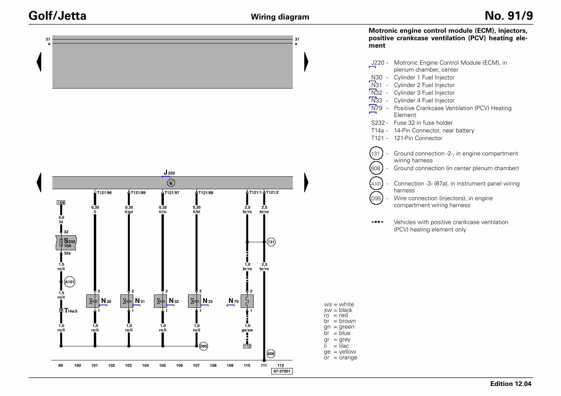
Golf/Jetta No. 91/9Motronic engine control module (ECM), injectors,positive crankcase ventilation (PCV) heating ele-ment
J220 - Motronic Engine Control Module (ECM), inplenum chamber, center
N30 - Cylinder 1 Fuel InjectorN31 - Cylinder 2 Fuel InjectorN32 - Cylinder 3 Fuel InjectorN33 - Cylinder 4 Fuel InjectorN79 - Positive Crankcase Ventilation (PCV) Heating
ElementS232 - Fuse 32 in fuse holderT14a - 14-Pin Connector, near batteryT121 - 121-Pin Connector
131 - Ground connection -2-, in engine compartmentwiring harness
608 - Ground connection (in center plenum chamber)
A101 - Connection -3- (87a), in instrument panel wiringharness
D95 - Wire connection (injectors), in enginecompartment wiring harness
- - Vehicles with positive crankcase ventilation(PCV) heating element only
31a
31a
97-93806
J220
M
T6k/5 T6k/2
V192
1
S28320A
2
18
ro1,5
ro1,5
T10/3
bl/gn0,5
T121/22
T6k/1
br/ro1,5
177
114 115 116 117 118 119 120 121 122 123 124 125 126113
E7
T121/5
T121/52
T121/71
sw0,35
T121/51
ws1,0
gn0,35
G39
T121/70
ws0,35
bl/ge1,5
T6c/6 T6c/2 T6c/5 T6c/1 T6c/4 T6c/3
gn0,35
E7
bl/gn0,35
Edition 12.04
Wiring diagram
ws = whitesw = blackro = redbr = browngn = greenbl = bluegr = grey
ge = yellowor = orange
li = lilac
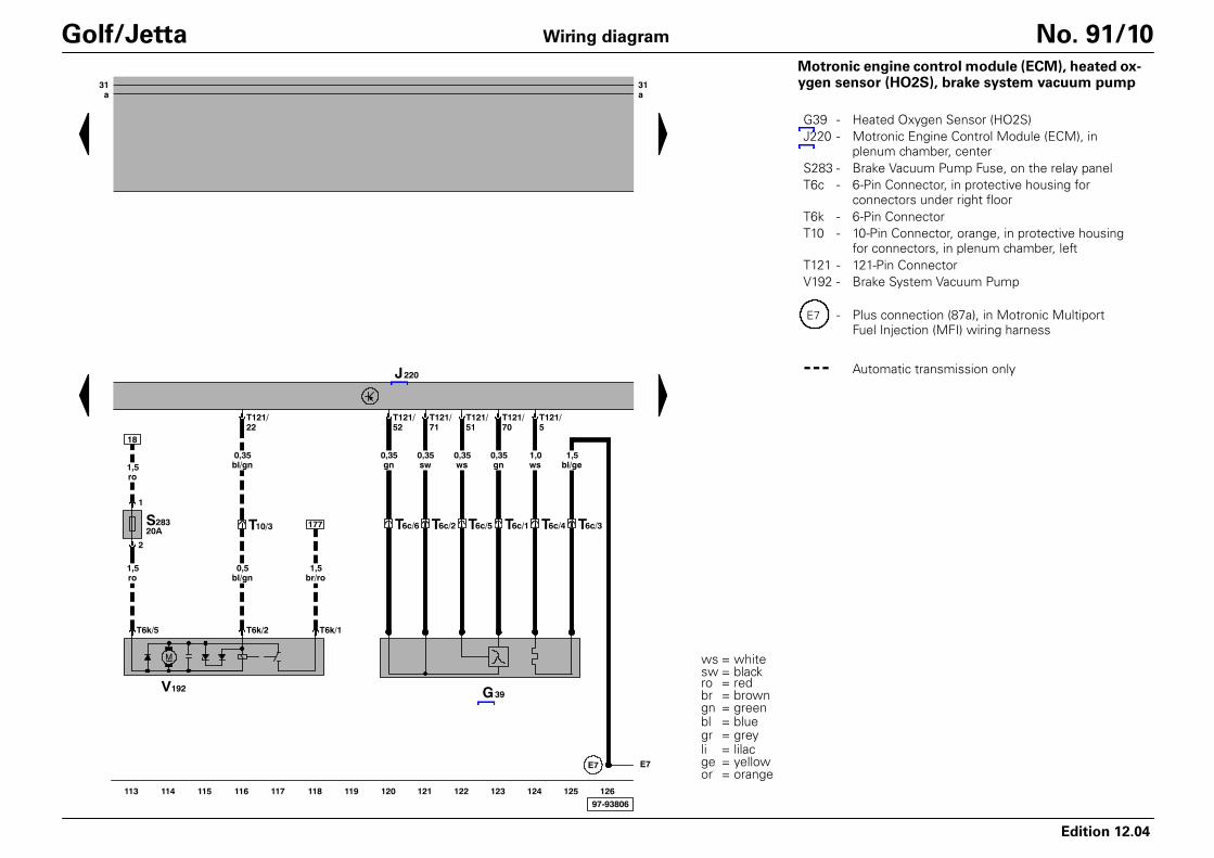
Golf/Jetta No. 91/10Motronic engine control module (ECM), heated ox-ygen sensor (HO2S), brake system vacuum pump
G39 - Heated Oxygen Sensor (HO2S)J220 - Motronic Engine Control Module (ECM), in
plenum chamber, centerS283 - Brake Vacuum Pump Fuse, on the relay panelT6c - 6-Pin Connector, in protective housing for
connectors under right floorT6k - 6-Pin ConnectorT10 - 10-Pin Connector, orange, in protective housing
for connectors, in plenum chamber, leftT121 - 121-Pin ConnectorV192 - Brake System Vacuum Pump
E7 - Plus connection (87a), in Motronic MultiportFuel Injection (MFI) wiring harness
- - - Automatic transmission only

97-93807
31a
31a
E30
G130
T4f/2
1,0 ws
T4f/4
T121/63
T121/69
bl0,35
sw0,35
T121/68
ws1,0
sw1,0
gr1,0
T4f/1
1,5 bl/ro
T4f/3
br0,35
li/ro0,35
1
N80
2
T121/64
bl/ge1,5
J220
128 129 130 131 132 133 134 135 136 137 138 139 140127
E7
2/87
3/85
299V101
4/86
bl/ge1,5
J
ws/ro4,0
1
br4,0
52
gr/br1,0
gr/br0,35
T121/9
D103
1/30
ro6,0
8
2
M
bl/ro2,5
E7 E30
Edition 12.04
Wiring diagram
ws = whitesw = blackro = redbr = browngn = greenbl = bluegr = grey
ge = yellowor = orange
li = lilac
Golf/Jetta No. 91/11Motronic engine control module (ECM), secondaryair injection (AIR) pump motor, secondary air injec-tion (AIR) pump relay, oxygen sensor (O2S) behindthree way catalytic converter (TWC), evaporativeemission (EVAP) canister purge regulator valve
G130 - Oxygen Sensor (O2S) behind Three WayCatalytic Converter (TWC)
J220 - Motronic Engine Control Module (ECM), inplenum chamber, center
J299 - Secondary Air Injection (AIR) Pump Relay, inprotective housing, in engine compartment,left, production control number (100)
N80 - Evaporative Emission (EVAP) Canister PurgeRegulator Valve
T4f - 4-Pin Connector, in protective housing forconnectors under right floor
T121 - 121-Pin ConnectorV101 - Secondary Air Injection (AIR) Pump Motor
E7 - Plus connection (87a), in Motronic MultiportFuel Injection (MFI) wiring harness
D103 - Wire connection -3-, in engine compartmentwiring harness
E30 - Connection (87a), in wiring harness engine

31a
31a
97-37004
3
2
F47
ro/sw1,0
1
4
F
A18
S1310A
13a
ro/br1,0
13
ro6,0
15
sw/ro0,35
T121/56
T10e/4
ws/ge1,0
T10e/5
A20
ws/ge0,35
E30
sw/bl1,0
ro/sw1,0
T121/55
E30
A20
185
sw/bl0,5
J220
142 143 144 145 146 147 148 149 150 151 152 153 154141
ws/ro0,35
T10w/4
ws/ro1,0
F36
sw/bl1,0
T121/39
gn0,35
ro/li0,35
3 4
T121/27
G70
bl/ge1,5
2
sw0,35
5
T121/29
T121/53
li/gn0,35
1
T121/26
T4q/2
T4q/3
Edition 12.04
Wiring diagram
ws = whitesw = blackro = redbr = browngn = greenbl = bluegr = grey
ge = yellowor = orange
li = lilac
Golf/Jetta No. 91/12Motronic engine control module (ECM), mass airflow (MAF) sensor, brake light switch, brake vac-uum vent valve switch for cruise control, clutch va-cuum vent valve switch
F - Brake Light SwitchF36 - Clutch Vacuum Vent Valve SwitchF47 - Brake Vacuum Vent Valve Switch for cruise
controlG70 - Mass Air Flow (MAF) SensorJ220 - Motronic Engine Control Module (ECM), in
plenum chamber, centerS13 - Fuse 13 in fuse holderT4q - 4-Pin ConnectorT10e - 10-Pin Connector, black, in protective housing
for connectors, in plenum chamber, leftT10w- 10-Pin Connector, white, in protective housing
for connectors, in plenum chamber, leftT121 - 121-Pin Connector
A18 - Wire connection (54), in instrument panel
A20 - Wire connection (15a), in instrument panelwiring harness
- Manual transmission only

97-37005
E30E30
T121/76
sw/ws0,35
T121/38
ws0,35
T121/75
bl/gr0,35
T10e/3 T10e/9
T10e/1
sw/ge0,35
sw/ge0,35
ws0,35
bl0,35
sw/bl0,35
T10s/7
T10s/5
T10s/4
T10s/2
T10s/6
3 2 0 1
T121/57
T10e/2
T10s/3
ro/ge0,35
A20
ro/ge0,35
A20
17/30
23/87
J1718/C
21/31
S2/5
24/TK 19/86
16/85
T121/65
li/ws0,5
T6/2
S3/6
sw1,0
S3/3
21
li/ws0,5
S3/5
br/ge0,5
S3/1
210
li/ws0,5
A125
T75/72
li/ws0,35
T121/54
A27
T10/6
bl/ws0,35
0,35 bl/ws
A27
31
d
31a
J220
J234
S3/4
20
4
22/50
S3/2
156 157 158 159 160 161 162 163 164 165 166 167 168155
gn/br0,35
T121/37
T10/9
E45 E227
Edition 12.04
Wiring diagram
ws = whitesw = blackro = redbr = browngn = greenbl = bluegr = grey
ge = yellowor = orange
li = lilac
Golf/Jetta No. 91/13Motronic engine control module (ECM), cruise con-trol switch, fuel pump (FP) relay
E45 - Cruise Control SwitchE227 - Cruise Control Push Button (SET)J17 - Fuel Pump (FP) RelayJ220 - Motronic Engine Control Module (ECM), in
plenum chamber, centerJ234 - Airbag Control ModuleT6 - 6-Pin Connector, brown, in protective housing
for connectors, in plenum chamber, leftT10 - 10-Pin Connector, orange, in protective housing
for connectors, in plenum chamber, leftT10e - 10-Pin Connector, black, in protective housing
for connectors, in plenum chamber, leftT10s - 10-Pin Connector, near steering columnT75 - 75-Pin ConnectorT121 - 121-Pin Connector
A20 - Wire connection (15a), in instrument panelwiring harness
A27 - Wire connection (vehicle speed signal), ininstrument panel wiring harness
A125 - Connection (crash signal) in instrument panelwiring harness
- Vehicles with cruise control only.Vehicles with Multi-function steering wheel ⇒Wiring diagram Multi-function steering wheelfor cruise control and radio

97-37006
bl4,0
504
A27
G6
1 3
4 2
GM
S22815A
28a
bl/ro1,5
G32
1
2
269
li/sw0,35
br/ws0,35
T14a/9
84
br/ws0,5
br/ws1,0
br/ws0,5
li/ro0,35
br/ws0,5
10A
34a
34
bl4,0
A100
S234
A99
ge/sw1,0
28
223
br/ws0,35
218
br/ws0,35
E30
10A
43a
43
bl/ge2,5
S243
bl4,0
E30
T6/5
99
bl4,0
bl4,0
ge/sw1,0
bl/ge2,5
A27
ef
g
br1,5
br2,5
S1/1
42
br4,0
135
31
d
49
br1,5
ge/sw1,0
T14a/6
118
1,5 br/ro
bl/ge1,0
A151
78
170 171 172 173 174 175 176 177 178 179 180 181 182169
T6/6
ge/sw1,0
110
Edition 12.04
Wiring diagram
ws = whitesw = blackro = redbr = browngn = greenbl = bluegr = grey
ge = yellowor = orange
li = lilac
Golf/Jetta No. 91/14Fuel pump (FP), fuel level sensor, engine coolantlevel (ECL) sensor
G - Fuel Level SensorG6 - Fuel Pump (FP)G32 - Engine Coolant Level (ECL) SensorS228 - Fuse 28 in fuse holderS234 - Fuse 34 in fuse holderS243 - Fuse 43 in fuse holderT6 - 6-Pin Connector, brown, in protective housing
for connectors, in plenum chamber, leftT14a - 14-Pin Connector, near battery
42 - Ground connection, beside steering column
49 - Ground connection, on steering column
135 - Ground connection -2-, in instrument panelwiring harnes
269 - Ground connection (sensor ground) -1-, ininstrument panel wiring harness
504 - Threaded connection -1- (87) on the relay plate
A99 - Connection -1- (87), in instrument panel wiringharness
A100 - Connection -2- (87), in instrument panel wiringharness
A151 - Connection -4- (87), in instrument panel wiringharness
E30 - Connection (87a), in wiring harness engine
- Vehicles with Multi-Function Indicator (MFI)only
- - - Automatic transmission only
- - Vehicles with positive crankcase ventilation(PCV) heating element only

97-37007
T32/28
J285
gn0,35
T32/10
gn/sw0,35
7a
F1
2
T14a/2
sw/gn1,0
S710A
T14a/3
ws/bl0,5
gn0,35
sw2,5
7
gn/sw0,5
23
B163 K3
T14a/1
sw/ws1,0
1
S57,5A
5
G22
5a
sw/bl0,5
br0,5
3
sw/gn1,0
152
43
184 185 186 187 188 189 190 191 192 193 194 195 196183
A27
ef
g
A27
ef
g
Edition 12.04
Wiring diagram
ws = whitesw = blackro = redbr = browngn = greenbl = bluegr = grey
ge = yellowor = orange
li = lilac
Golf/Jetta No. 91/15Instrument cluster, oil pressure switch, speedome-ter vehicle speed sensor (VSS), oil pressure warninglight
F1 - Oil Pressure SwitchG22 - Speedometer Vehicle Speed Sensor (VSS)J285 - Control module with indicator unit in instrument
panel insertK3 - Oil Pressure Warning LightS5 - Fuse 5 in fuse holderS7 - Fuse 7 in fuse holderT14a - 14-Pin Connector, near batteryT32 - 32-Pin Connector, blue
B163 - Plus connection -1- (15) in wiring harnessinterior
97-37008
K105
3G K2
J285
1G
H3
G5 G21
K28
A27
bl/ws0,35
li/sw0,35
li0,35
84 2
bl0,35
T32/5T32/8 T32/3 T32/12T32/7T32/22
li/ro0,35
br/ws0,35
br/ge0,5
T32/21
A13
br/ge0,35
160A27
ef
g
198 199 200 201 202 203 204 205 206 207 208 209 210197
Edition 12.04
Wiring diagram
ws = whitesw = blackro = redbr = browngn = greenbl = bluegr = grey
ge = yellowor = orange
li = lilac
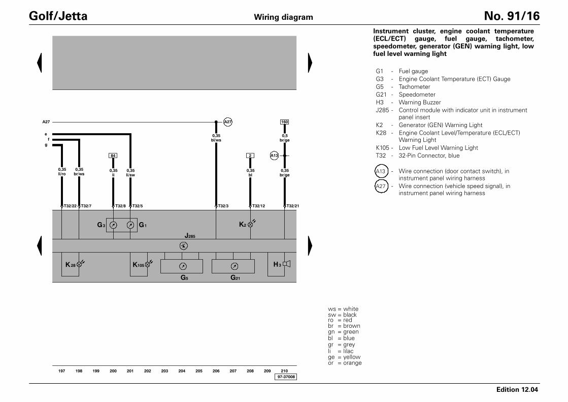
Golf/Jetta No. 91/16Instrument cluster, engine coolant temperature(ECL/ECT) gauge, fuel gauge, tachometer,speedometer, generator (GEN) warning light, lowfuel level warning light
G1 - Fuel gaugeG3 - Engine Coolant Temperature (ECT) GaugeG5 - TachometerG21 - SpeedometerH3 - Warning BuzzerJ285 - Control module with indicator unit in instrument
panel insertK2 - Generator (GEN) Warning LightK28 - Engine Coolant Level/Temperature (ECL/ECT)
Warning LightK105 - Low Fuel Level Warning LightT32 - 32-Pin Connector, blue
A13 - Wire connection (door contact switch), ininstrument panel wiring harness
A27 - Wire connection (vehicle speed signal), ininstrument panel wiring harness

97-37009
T16/7
gr/ws0,5
T32/25K
A76
gr/ws0,35
49
or/br0,35
or/sw0,35
54
gr/ws0,35
65
T32a/5W
J285
bl/gn0,35
bl0,35
T32a/25
bl/gr0,35
T32a/23
T32a/24
180
br/ws0,35
J119
K132
J533
K31
K83
T32a/19can-l can-hT32a/20
T6e/3
E86 E109
T6e/1 T6e/2 T6e/4
212 213 214 215 216 217 218 219 220 221 222 223 224211
G17ϑ
2
1
178
br/ws0,35
br/ge0,35
T32a/26
Edition 12.04
Wiring diagram
ws = whitesw = blackro = redbr = browngn = greenbl = bluegr = grey
ge = yellowor = orange
li = lilac
Golf/Jetta No. 91/17Instrument cluster, multi-function indicator (MFI),outside air temperature sensor, electronic powercontrol (EPC) warning lamp, cruise control indicatorlight, malfunction indicator lamp
E86 - Multi-Function Indicator Mode Select SwitchE109 - Multi-Function Indicator Memory SwitchG17 - Outside Air Temperature SensorJ119 - Multi-function Indicator (MFI)J285 - Control module with indicator unit in instrument
panel insertJ533 - Data Bus On Board Diagnostic InterfaceK31 - Cruise Control Indicator LightK83 - Malfunction Indicator Lamp (MIL)K132 - Electronic Power Control (EPC) Warning LampT6e - 6-Pin ConnectorT16 - Data Link Connector (DLC), below instrument
panel, leftT32 - 32-Pin Connector, blueT32a - 32-Pin Connector, green
A76 - Connection (K-diagnosis wire), in instrumentpanel wiring harness
- Vehicles with Multi-Function Indicator (MFI)only