


Languages
Pages
Legal

USER’S MANUAL – Part 1
Configurator
VERSION: 0.2.2.1


NEO Configurator User’s Manual
VERSION 0.2.2.1
LDA Audio Tech. 31 Severo Ochoa, Malaga, Spain - www.lda-audiotech.com 1
CONTENT
PART 1
1. INTRODUCTION ............................................................................................................... 3
1.1. Installation .................................................................................................................. 3
1.2. Login ........................................................................................................................... 4
2. OVERVIEW AND PREFERENCES ................................................................................... 5
2.1. User Interface Description .......................................................................................... 5
2.1.1. “Project” menu ................................................................................................... 6
2.1.2. “View” menu ...................................................................................................... 7
2.1.3. “Tools” menu ..................................................................................................... 8
2.1.4. “Help” menu ....................................................................................................... 9
2.2. Preferences .............................................................................................................. 10
2.2.1. Language preferences ..................................................................................... 10
2.2.2. Time & Date preferences ................................................................................. 11
2.2.3. Users preferences ........................................................................................... 12
2.2.4. Contact info preferences .................................................................................. 13
3. PROJECT SETUP ........................................................................................................... 15
3.1. New project ............................................................................................................... 15
3.2. Add devices .............................................................................................................. 15
3.2.1. Controller ......................................................................................................... 16
3.2.2. PA Microphones .............................................................................................. 16
3.2.3. E Microphones ................................................................................................. 18
3.2.4. PA Zone Controllers ........................................................................................ 20
3.3. Assign devices .......................................................................................................... 22
3.3.1. Assign the system controller ............................................................................ 23
3.3.2. Assign PA or E microphones ........................................................................... 25
3.4. Link System .............................................................................................................. 26
3.4.1. Import System ................................................................................................. 26
3.4.2. Export System ................................................................................................. 26
3.4.3. Unlink system .................................................................................................. 27
3.5. Update devices firmware .......................................................................................... 27
NEO Configurator User’s Manual
VERSION 0.2.2.1
LDA Audio Tech. 31 Severo Ochoa, Malaga, Spain - www.lda-audiotech.com 2
4. SYSTEM CONFIGURATION ........................................................................................... 29
4.1. System Devices View ............................................................................................... 31
4.1.1. Root ................................................................................................................. 31
4.1.2. Microphones .................................................................................................... 33
4.1.3. Controllers ....................................................................................................... 33
4.1.4. Extensions ....................................................................................................... 41
4.1.5. Accessories ..................................................................................................... 41
4.2. Public Address System View .................................................................................... 43
4.2.1. Root ................................................................................................................. 43
4.2.2. Sources ........................................................................................................... 44
4.2.3. Matrix .............................................................................................................. 47
4.2.4. Zones .............................................................................................................. 48
4.3. Voice Alarm System View ......................................................................................... 52
4.3.1. Root ................................................................................................................. 52
4.3.2. Sources ........................................................................................................... 53
4.3.3. Matrix .............................................................................................................. 56
4.3.4. Zones .............................................................................................................. 57
PART 2
5. EVENTS ..............................................................................................................................
5.1. Triggers ......................................................................................................................
5.2. Conditions ..................................................................................................................
5.3. Actions .......................................................................................................................
5.4. Event creation ............................................................................................................
5.5. Examples ...................................................................................................................
5.5.1. Sequence of evacuation: alternating EVAC and ALERT ......................................
5.5.2. Integration with a Fire Alarm Panel ......................................................................
5.5.3. Scheduled announcements .................................................................................
5.5.4. Route sources and play messages from MPS-8Z ................................................

NEO Configurator User’s Manual
VERSION 0.2.2.1
LDA Audio Tech. 31 Severo Ochoa, Malaga, Spain - www.lda-audiotech.com 3
1. INTRODUCTION
NEO Configurator is a simple and intuitive computer interface that allows to configure the
most advanced and powerful parameters of NEO system. NEO Configurator is intended mainly
for installers and distributors, however, thanks to the possibility of configure different user profiles,
it is also a good tool for basic operation of the system from remote computers.
The instructions and screenshots included in this user’s manual correspond to NEO
Configurator version 0.2.2.1.
1.1. Installation
LDA Audio Tech provides the installer for NEO Configurator in an executable file. Simply
follow the instruction of the setup wizard to install the software in the computer.
Compatible operating systems:
▪ Windows XP
▪ Windows Vista
▪ Windows 7
▪ Windows 8
▪ Windows 8.1
▪ Windows 10
NOTE: It is recommended to run NEO Configurator always as Administrator.
NEO Configurator User’s Manual
VERSION 0.2.2.1
LDA Audio Tech. 31 Severo Ochoa, Malaga, Spain - www.lda-audiotech.com 4
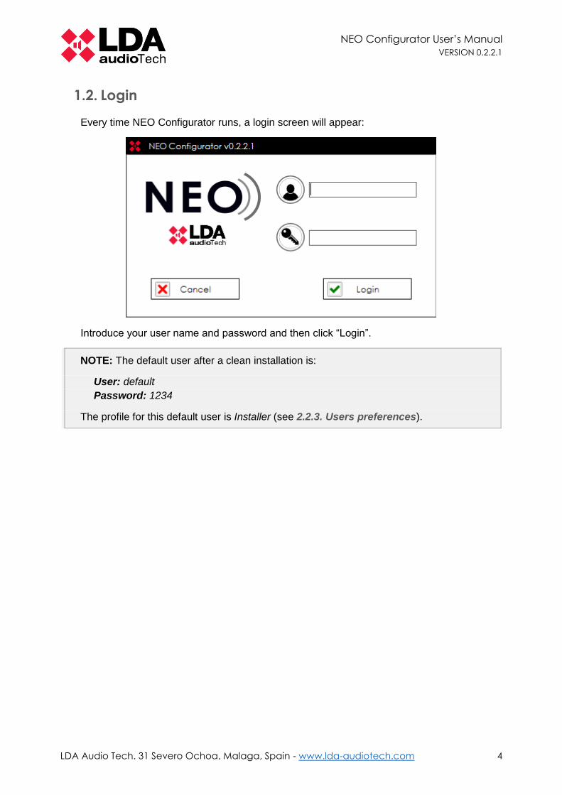
1.2. Login
Every time NEO Configurator runs, a login screen will appear:
Introduce your user name and password and then click “Login”.
NOTE: The default user after a clean installation is:
User: default
Password: 1234
The profile for this default user is Installer (see 2.2.3. Users preferences).

NEO Configurator User’s Manual
VERSION 0.2.2.1
LDA Audio Tech. 31 Severo Ochoa, Malaga, Spain - www.lda-audiotech.com 5
2. OVERVIEW AND PREFERENCES
2.1. User Interface Description
After NEO Configurator is opened, you get a blank window with no project loaded as shown
below:
The menu bar at the top contains 4 menus: Project, View, Tools and Help. They are all
described in the sections 2.1.1 to 2.1.4.
At the top right hand corner is shown the user name and user profile:
The status bar at the bottom includes the following status indicators:
▪ SYSCTRL: This status has 3 indicators:
o Indicator 1: The system (project in NEO Configurator) has a
Controller.
o Indicator 2: The Controller in NEO Configurator is assigned
to a physical controller.
o Indicator 3: NEO Configurator can “see” the assigned physical
controller in the network (so it is possible to live link to the device).
▪ SYSLINK: The system (NEO Configurator) is live linked with the physical
system. Every change made in NEO Configurator is updated instantly in the physical
system and vice versa.

NEO Configurator User’s Manual
VERSION 0.2.2.1
LDA Audio Tech. 31 Severo Ochoa, Malaga, Spain - www.lda-audiotech.com 6
▪ SYSDATA: The project in NEO Configurator is synchronized with the
physical system, so all the parameters are the same in NEO Configurator and the
device. NEO Configurator must be live linked (SYSLINK on) in order to check the sync
status. After a change is made in either side, the indicator will turn black briefly until
the change is updated in both ends (NEO Configurator and the physical device).
NOTE: Some short blinking of SYSDATA may happen during normal operation.
▪ EMG: It reports NEO is in emergency state.
▪ FLT: It reports NEO is reporting any fault.
▪ DIS: It reports one or many zones in NEO are disarmed.
▪ UPDATING: It indicates when NEO Configurator is sending data to the
physical device when exporting a project (see 3.4. Link System).
2.1.1. “Project” menu
▪ NEW: Creates a new Project with its corresponding views (see 3.1. New project). The
default name for the new project is “newProject.neo”.
▪ OPEN: Opens an existing project. If the project already had added devices, they will
appear in the “Devices view”.
▪ CLOSE: Closes the current project.
▪ SAVE: Saves the complete project with the current name and location. For new
projects the “SAVE AS” window will appear instead.
▪ SAVE AS: Saves the complete project with a name and location chosen by the user.
NOTE: You can only save a project if your user profile is Installer (see 2.2.3. Users
preferences).

NEO Configurator User’s Manual
VERSION 0.2.2.1
LDA Audio Tech. 31 Severo Ochoa, Malaga, Spain - www.lda-audiotech.com 7
▪ PRINT: Automatically generates a system report with all the configurations and
parameters of the system and prompt you to print it with a system printer. The detail
level of this report will depend on the user profile (see 2.2.3. Users preferences).
▪ PRINT TO FILE: Automatically generates a system report with all the configurations
and parameters of the system and prompt you to save it as PDF in the computer. The
detail level of this report will depend on the user profile (see 2.2.3. Users
preferences).
▪ EXIT: Exits the software.
NOTE: Adobe Acrobat Reader is required to ensure the proper operation of the PRINT
function.
2.1.2. “View” menu
From this menu, you can select any of the 3 System Views:
▪ Voice Alarm System
▪ Public Address System
▪ System Devices
The System Views allows configuring and setting up all the parameters of the system. It is
the main functional area of NEO Configurator. Each one of these views are shown in the left panel
of the main window (see screenshots below).
A detailed description of every System View is explained in chapter 4. SYSTEM
CONFIGURATION.
NOTE: View menu is only active when there is an open project.

NEO Configurator User’s Manual
VERSION 0.2.2.1
LDA Audio Tech. 31 Severo Ochoa, Malaga, Spain - www.lda-audiotech.com 8
2.1.3. “Tools” menu
▪ IMPORT / EXPORT / UNLINK SYSTEM: These tools are used to live link and unlink
NEO Configurator to the physical system (see 3.4. Link System).

NEO Configurator User’s Manual
VERSION 0.2.2.1
LDA Audio Tech. 31 Severo Ochoa, Malaga, Spain - www.lda-audiotech.com 9
▪ SEARCH DEVICES: Loads the NEO Discovery tool that allows assigning a NEO
Configurator project to a physical system (see 3.3. Assign devices).
▪ UPDATE DEVICES: Loads a tool to update the firmware of NEO devices (see 3.5.
Update devices).
▪ EXPORT / IMPORT EVENTS FROM / TO FILE: Saves into a computer file all the
events created in the system (see chapter 5. EVENTS to know more about events).
▪ PREFERENCES: Edit the general preferences of NEO Configurator software (see 2.2.
Preferences). These preferences are common to all the projects opened from the
same computer.
▪ EXPORT / IMPORT PREFERENCES: Saves into a computer file all the preferences
of NEO Configurator software.
NOTE: Some tools may be restricted depending on your user profile (see 2.2.3. Users
preferences).
2.1.4. “Help” menu
▪ HELP: Displays the help documents of the project. This option is not yet implemented
in this version.
▪ SUPPORT: Displays contact information for the user. Additional support information
can be added in this window from Contact info preferences (see 2.2.4). Only the
Installer can edit this information (see 2.2.3).
▪ ABOUT: Displays version number and manufacturer information.
▪ UPDATE: Check with LDA Audio Tech servers if a new version of NEO Configurator
is available. This option is not implemented yet in this version.

NEO Configurator User’s Manual
VERSION 0.2.2.1
LDA Audio Tech. 31 Severo Ochoa, Malaga, Spain - www.lda-audiotech.com 10
2.2. Preferences
From the Tools menu you can open the Preferences window to configure NEO Configurator
software. This window contains 4 tabs: Language, Date & Time, Users, Contact Info.
NOTE: You can only access to Preferences if your user profile is Installer or Maintainer
(see 2.2.3. Users preferences).
2.2.1. Language preferences
From this tab, you can change the user interface language of NEO Configurator:
1. Select the language from the panel “Available languages”.
2. Click on “Load”.
3. NEO Configurator will prompt if you want to restart the application in order to apply the
new language. Click “Yes”.
NOTE: All unsaved changes in the project will be lost.
4. NEO Configurator will be closed.
5. Open again NEO Configurator. The new language will be applied.

NEO Configurator User’s Manual
VERSION 0.2.2.1
LDA Audio Tech. 31 Severo Ochoa, Malaga, Spain - www.lda-audiotech.com 11
2.2.2. Time & Date preferences
In this tab, you can check the time that is using both NEO Configurator and the physical
system.
NOTE: NEO Configurator’s time and date is taken directly from the computer’s clock and
it is automatically synced to the physical system every time the system is live linked with
NEO Configurator.
You can also change the date format displayed within NEO Configurator:
1. Select the desired date format from the panel “Available date formats”.
2. Click on “Load”.
3. NEO Configurator will prompt if you want to restart the application in order to apply the
new date format. Click “Yes”.
NOTE: All unsaved changes in the project will be lost.
4. NEO Configurator will be closed.
5. Open again NEO Configurator. The new date format will be applied.

NEO Configurator User’s Manual
VERSION 0.2.2.1
LDA Audio Tech. 31 Severo Ochoa, Malaga, Spain - www.lda-audiotech.com 12
2.2.3. Users preferences
In this tab, you can add or edit many different users for NEO Configurator. Every user can
optionally have a password.
Each user will have a profile assigned: Reporter, Operator, Maintainer or Installer. Every
profile has different permissions for the System Views and for some NEO Configurator Tools:
REPORTER OPERATOR MAINTAINER INSTALLER
SYSTEM VIEWS
Voice Alarm Only view Only view Only view Configuration
Public Address Only view Configuration Configuration Configuration
Devices Only view Only view Configuration Configuration
NEO Configurator
Tools
Save Project Disabled Disabled Disabled Enabled
Preferences Disabled Disabled Enabled * Enabled
Export / Import Preferences
Disabled Disabled Enabled Enabled
Export System Disabled Disabled Enabled Enabled
* Maintainer cannot create new users with Installer profile.
The lower panel “Available users” indicate all the users that are currently configured in NEO
Configurator.
The upper panel “Users” is used to create a new user or to edit an existing user.

NEO Configurator User’s Manual
VERSION 0.2.2.1
LDA Audio Tech. 31 Severo Ochoa, Malaga, Spain - www.lda-audiotech.com 13
CREATE A NEW USER
1. Click “New” to clean the “Users” panel.
2. Edit every field in the “Users” panel. Both “Name” and “Profile” are mandatory fields.
3. Click on “Save”.
4. The new user will appear in the “Available technicians” panel.
EDIT AN EXISTING USER
1. Select the existing user from the “Available users” panel.
2. Click on “Edit”. The user details will appear in the “Users” panel.
3. Modify the corresponding fields in “Users” panel.
4. Click on “Save”.
DELETE AN EXISTING USER
1. Select the existing user from the “Available users” panel.
2. Click on “Delete”.
2.2.4. Contact info preferences
This tab is intended to edit support information that will appear in the “Support” window (see
2.1.4. “Help” menu):
The lower panel “Available technicians” indicate all the contact details that are currently saved
in NEO Configurator.
The upper panel “Contact Info” is used to create a new contact or to edit an existing contact.

NEO Configurator User’s Manual
VERSION 0.2.2.1
LDA Audio Tech. 31 Severo Ochoa, Malaga, Spain - www.lda-audiotech.com 14
CREATE A NEW CONTACT
1. Click “New” to clean the “Contact Info” panel.
2. Edit every field in the “Contact Info” panel. The only mandatory field is “Technician name”.
3. Click on “Save”.
4. The new contact will appear in the “Available technicians” panel.
EDIT AN EXISTING CONTACT
1. Select the existing contact from the “Available technicians” panel.
2. Click on “Edit”. The contact details will appear in the “Contact Info” panel.
3. Modify the corresponding fields in “Contact Info” panel.
4. Click on “Save”.
DELETE AN EXISTING CONTACT
1. Select the existing contact from the “Available technicians” panel.
2. Click on “Delete”.

NEO Configurator User’s Manual
VERSION 0.2.2.1
LDA Audio Tech. 31 Severo Ochoa, Malaga, Spain - www.lda-audiotech.com 15
3. PROJECT SETUP
3.1. New project
In NEO Configurator, a project is a complete NEO system with all their parameters and events
configurations.
In order to start using NEO Configurator, you should either:
▪ Create a new project (Project -> New).
▪ Open an existing project (Project -> Open).
If you have a previously installed NEO system, but you do not have the corresponding project
file, you can import this system into NEO Configurator by following these steps:
1. Create a new project (Project -> New).
2. Search the main controller of that system (see 3.3. Assign devices).
3. Add the controller to the NEO Configurator project (see 3.3. Assign devices).
4. Import the system (see 3.4. Link System).
3.2. Add devices
A NEO system is composed of at least one NEO Controller (NEO 8060). Additionally, a NEO
system can contain any of the following devices:
▪ Microphones:
o MPS-8Z paging microphones (PA Microphones)
o VAP-1 voice alarm panels (E Microphones)
▪ NEO Extensions:
o NEO 8120E
o NEO 4250E
▪ Accesories:
o VCC-64 volume and channel controller (PA Zone Controller)
NOTE: Every project can contain just 1 single controller. If you have more than 1
controller, it means you have many different systems. Each one of these systems will be
a separate NEO Configurator project.
There are 2 ways of adding devices into a system:
▪ Manually as virtual devices (see sections 3.2.1 to 3.2.4).
▪ From an existing physical system connected to the same network as the computer
(see 3.3. Assign devices).
NOTE: If you add virtual devices as described below, these virtual devices can later be
assigned to physical devices (see 3.3. Assign devices) and thus export all the
configurations to that system (see 3.4.2. Export System).

NEO Configurator User’s Manual
VERSION 0.2.2.1
LDA Audio Tech. 31 Severo Ochoa, Malaga, Spain - www.lda-audiotech.com 16
3.2.1. Controller
ADD A VIRTUAL CONTROLLER
In order to add a virtual controller in a blank project, follow the steps below:
1. In System Devices view, right-click on “Controllers”
2. Click on “Add Controller”:
REMOVE A CONTROLLER
To remove a controller simply right-click on the added controller and then click on “Remove
Device”:
NOTE: In order to add or remove controllers your user profile must be Installer or
Maintainer (see 2.2.3. Users preferences).
3.2.2. PA Microphones
ADD A VIRTUAL PA MICROPHONE
Before adding any microphone, you need to make sure you already have a controller in your
system. To add a virtual PA Microphone, follow the steps below:
1. In Public Address View, click on “Microphones”:
2. In the Tabs panel (middle) click on “General”:

NEO Configurator User’s Manual
VERSION 0.2.2.1
LDA Audio Tech. 31 Severo Ochoa, Malaga, Spain - www.lda-audiotech.com 17
3. In the Edition panel (right) you can configure the ACSI Direction of the PA Microphone
you want to add. Click on this field to select the desired ACSI Direction/Priority:
NOTE: The ACSI Direction or Priority corresponds to the priority level of the device
in relation to all the ACSI devices (MPS-8Z or VAP-1) of the system. See the devices
user’s manuals for further information.
4. Click on “Add”.
5. The new PA Microphone will appear below:
6. Now you can optionally edit the “Description” of the PA Microphone by double clicking in
the corresponding field.
REMOVE A PA MICROPHONE
To remove a PA Microphone you have 2 options:
Option 1: From Public Address View
1. In Public Address View, click on “Microphones”.
2. In the Tabs panel (middle) click on “General”.
3. In the Edition panel (right) click on “Delete” on the PA Microphone you want to remove.
Option 2: From System Devices View
1. In System Devices View, right-click on the PA Microphone you want to remove.
2. Click on “Remove Device”.
NOTE: In order to add or remove PA Microphones your user profile must be Installer or
Maintainer (see 2.2.3. Users preferences).

NEO Configurator User’s Manual
VERSION 0.2.2.1
LDA Audio Tech. 31 Severo Ochoa, Malaga, Spain - www.lda-audiotech.com 18
3.2.3. E Microphones
ADD A VIRTUAL EMERGENCY MICROPHONE
Before adding any emergency microphone, you need to make sure you already have a
controller in your system. To add a virtual E Microphone, follow the steps below:
1. In Voice Alarm View, click on “E Microphones”:
2. In the Tabs panel (middle) click on “General”:
3. In the Edition panel (right) you can configure the ACSI Direction of the E Microphone you
want to add. Click on this field to select the desired ACSI Direction/Priority:
NOTE: The ACSI Direction or Priority corresponds to the priority level of the device
in relation to all the ACSI devices (MPS-8Z or VAP-1) of the system. See the devices
user’s manuals for further information.
4. Click on “Add”.
5. The new E Microphone will appear below:

NEO Configurator User’s Manual
VERSION 0.2.2.1
LDA Audio Tech. 31 Severo Ochoa, Malaga, Spain - www.lda-audiotech.com 19
6. Now you can optionally edit the “Description” of the E Microphone by double clicking in
the corresponding field.
REMOVE AN EMERGENCY MICROPHONE
To remove an E Microphone you have 2 options:
Option 1: From Voice Alarm View
1. In Voice Alarm View, click on “E Microphones”.
2. In the Tabs panel (middle), click on “General”.
3. In the Edition panel (right), click on “Delete” on the E Microphone you want to remove.
Option 2: From System Devices View
1. In System Devices View, right-click on the E Microphone you want to remove.
2. Click on “Remove Device”.
NOTE: In order to add or remove Emergency Microphones your user profile must be
Installer (see 2.2.3. Users preferences).

NEO Configurator User’s Manual
VERSION 0.2.2.1
LDA Audio Tech. 31 Severo Ochoa, Malaga, Spain - www.lda-audiotech.com 20
3.2.4. PA Zone Controllers
PA Zone Controllers are devices that manage the volume level and the source routed in a
single zone. When a VCC-64 Volume and Channel Controller is connected to the system, NEO
automatically detects it and adds it as a PA Zone Controller. This PA Zone Controller will appear
directly in NEO Configurator if you were live linked or after importing the system.
NOTE: PA Zone Controllers cannot be added from the Search device window as
described in 3.3. Assign devices. They are added automatically by NEO after they are
connected to the system.
You can also add PA Zone Controllers manually as virtual PA Zone Controllers that will be
automatically assigned to the physical VCC-64 as long as they have the same physical address.
ADD A VIRTUAL PA ZONE CONTROLLER
Before adding a PA Zone Controller, you need to make sure you already have a controller in
your system. To add a virtual PA Zone Controller, follow the steps below:
1. In System Devices View, click on “PA Zone Controllers”:
2. In the Tabs panel (middle) click on “General”:

NEO Configurator User’s Manual
VERSION 0.2.2.1
LDA Audio Tech. 31 Severo Ochoa, Malaga, Spain - www.lda-audiotech.com 21
3. In the Edition panel (right) you can configure the physical address that the PA Zone
Controller will have, as well as the zone which will be assigned to that physical address.
Click on these fields to select the desired values:
NOTE: The physical addresses 0 to 7 correspond with the 8 possible deep switch
configurations you can select in the VCC-64. See VCC-64 user’s manual for further
information.
4. Click on “Add”.
5. The new PA Zone Controller will appear below:
6. You can optionally edit the “Description” of the PA Zone Controller by double clicking in
the corresponding field.
REMOVE A PA ZONE CONTROLLER
To remove a PA Zone Controller you have 2 options:
Option 1: From Edition panel (right)
1. In System Devices View, click on “PA Zone Controller”.
2. In the Tabs panel (middle), click on “General”.
3. In the Edition panel (right), click on “Delete” next to the PA Zone Controller you want to
remove.
Option 2: From System Devices tree
1. In System Devices View tree (left panel), right-click on the PA Zone Controller you want
to remove.
2. Click on “Remove Device”.
NOTE: In order to add or remove PA Zone Controllers your user profile must be Installer
or Maintainer (see 2.2.3. Users preferences).

NEO Configurator User’s Manual
VERSION 0.2.2.1
LDA Audio Tech. 31 Severo Ochoa, Malaga, Spain - www.lda-audiotech.com 22
3.3. Assign devices
The devices within a project of NEO Configurator can be assigned to physical devices
connected to the same LAN network.
The assignation of NEO Configurator devices with physical devices is always done with the
tool Search device, located in the Tools menu:
Search Device can search all the devices which are connected within the same network
range as the computer’s IP configuration.
With the option “Search only for this IP” you can filter the results to show only the IP of a
specific NEO device:
NOTE: You can only modify the IP address to search while the box “Search only for this
IP” is unmarked.

NEO Configurator User’s Manual
VERSION 0.2.2.1
LDA Audio Tech. 31 Severo Ochoa, Malaga, Spain - www.lda-audiotech.com 23
We can assign manually the system controller and the microphones. PA Zone Controllers
are always assigned automatically as described in section 3.2.4.
3.3.1. Assign the system controller
CASE 1: The project is blank and no controller was previously added
From the Search Devices tool, we can add and assign a controller in one step, so there is no
need to previously add a virtual controller as described in section 3.2.1.
1. In the upper part of the window, select the controller you want to add and assign.
2. Click on “Add”.
3. The controller will appear in the lower panel “System Devices” and will automatically be
assigned) to your NEO Configurator project.
The 3 indicators in SYSCTRL will be on: because NEO Configurator (1 ON)
has a controller, (2 ON) has a physical device assigned to that controller and (3 ON) that physical
device is visible in the LAN.
CASE 2: The project had already a controller
The previously added controller could be either virtual (not assigned to any device) or could
have been assigned to another device (with a different MAC).
NOTE: It does not matter if the previously assigned device and the new one share the
same IP address. As long as they have a different MAC, it is required to re-assign the
controller to the new device.
A previously added controller (either virtual or already assigned) can be assigned to a
particular physical device by following these steps:
1. In the upper part of the window, select the new physical controller you want to assign.
2. Click on “Assign”.

NEO Configurator User’s Manual
VERSION 0.2.2.1
LDA Audio Tech. 31 Severo Ochoa, Malaga, Spain - www.lda-audiotech.com 24
3. The following windows will appear:
4. Click “Yes”.
5. You will have the new device assigned to the NEO Configurator project. SYSCTRL will
be like this: .
NOTE: There is no need to unassign the previous device before assigning the new
device.
UNASSIGN A CONTROLLER
If you click on “Unassign”, the physical controller will be unassigned from the project and it
will appear in red:
Moreover, the 3 indicators in SYSCTRL will be like this: , showing that (2 OFF)
there is no physical device assigned to the controller in the current project, but (3 ON) the
previously assigned device is still visible.

NEO Configurator User’s Manual
VERSION 0.2.2.1
LDA Audio Tech. 31 Severo Ochoa, Malaga, Spain - www.lda-audiotech.com 25
3.3.2. Assign PA or E microphones
Both PA microphones (MPS-8Z) and Emergency microphones (VAP-1) are ACSI devices,
therefore the way they are assigned into a NEO Configurator project is the same.
ACSI microphones share the same IP address as the system controller with an additional
number that indicates the ACSI address they have set. For example, 192.168.3.62@1 is a
microphone connected to the NEO Controller 192.168.3.62 at the ACSI address number 1.
In any NEO system, it is only possible to have 1 microphone installed per ACSI address. The
ACSI address of a physical microphone is set up from the device itself (see MPS-8Z or VAP-1
User’s Manual). Likewise, in a virtual microphone the ACSI address is specified from the moment
it is created (see sections 3.2.2 and 3.2.3).
After we assign a NEO Controller (see 3.3.1), we can have any of the following 3 cases:
CASE 1: A physical microphone shares the same ACSI address as a virtual
microphone
In this case, the physical microphone will be automatically assigned to the virtual microphone.
No further action required.
CASE 2: A physical microphone has a unique ACSI address (not in the software
project)
The physical microphone will remain unadded and unassigned in the NEO Configurator
project. This means that NEO Configurator will not be able to configure or operate them.
In order to add and assign it, follow the steps below:
1. In the Tools menu click on Search Devices.
2. In the upper part of the window, select the microphone you want to add and assign.
3. Click on “Add”.
4. The device will appear in the lower panel “System Devices” and will automatically be
assigned in your NEO Configurator project.
CASE 3: A virtual microphone has a unique ACSI address (not in the physical
system)
The virtual microphone will remain in the NEO Configurator project and it will be possible to
configure them virtually.
If a physical microphone with that same ACSI address is connected in the future, it will be
automatically assigned to the system and will adopt the configurations from this virtual
microphone.
NOTE: Microphones cannot be unassigned from a project. They just can be added or
removed from the project.

NEO Configurator User’s Manual
VERSION 0.2.2.1
LDA Audio Tech. 31 Severo Ochoa, Malaga, Spain - www.lda-audiotech.com 26
3.4. Link System
NEO Configurator can be live linked to the physical system and thus, all changes made in
NEO Configurator are updated immediately in the device and vice versa.
When we link the system, we have to choose what configuration we want to preserve: the
current configuration in the physical device or the current configuration in NEO Configurator
project.
3.4.1. Import System
Import System means that we will download the current configuration from the physical
system to the NEO Configurator project.
1. Before importing a system, we always have to assign the controller where we want to
import from (see 3.3.1. Assign the system controller).
2. In the “Tools” menu select “Import System”.
3. A message will appear telling that all the configuration in the current project will be lost
and substituted by the configuration of the physical system.
4. Click “Yes”.
NEO Configurator and the physical system will be live linked.
▪ The left panel background will turn green.
▪ A green spot will appear next to all the linked devices.
▪ The status bar indicator will turn green.
Import System can be used to load in NEO Configurator the current parameters of the
physical device so we can simply check them or start to work with them. We can also continue
working offline or unlinked as explained in 3.4.3. Unlink system.
3.4.2. Export System
Export System means that we will upload the current configuration from the NEO Configurator
project to the physical system.
1. Before exporting a system, we always have to assign the controller where we want to
export (see 3.3.1. Assign the system controller).
2. In the “Tools” menu select “Export System”.
3. A message will appear telling that all the configuration in the physical device will be lost
and substituted by the configuration of the NEO Configurator Project.
4. Click “Yes”.
NEO Configurator and the physical system will be live linked.
▪ The left panel background will turn green.
▪ A green spot will appear next to all the linked devices.
▪ The status bar indicator will turn green.

NEO Configurator User’s Manual
VERSION 0.2.2.1
LDA Audio Tech. 31 Severo Ochoa, Malaga, Spain - www.lda-audiotech.com 27
NOTE: If NEO system is in emergency state, it is not possible to export a NEO
Configurator project to the physical system.
Export System can be used to reset a system to the Installer’s custom configuration. Simply
open the project the Installer has created for the system (section 3.1), assign the physical system
(section 3.3) and export the system as described above.
3.4.3. Unlink system
If you want to work offline after importing or exporting the system, you can simply unlink the
system by clicking in “Unlink System” within the “Tools” menu.
▪ The left panel green background will switch off.
▪ The green spot next to the linked devices will disappear.
▪ The status bar indicator will turn black.
3.5. Update devices firmware
The “Update Devices Firmware” tool allows to update the firmware of any NEO device
connected to the network. After clicking in this tool, a Search Device window similar to the one
described in 3.3. Assign devices will appear:
You can update any device in the same network IP ranges as your computer, even though
the device belongs to a different system than the current NEO Configurator project.
NOTE: In order to use the “Update devices” tool, you must load a project first (see 3.1).

NEO Configurator User’s Manual
VERSION 0.2.2.1
LDA Audio Tech. 31 Severo Ochoa, Malaga, Spain - www.lda-audiotech.com 28
LOAD THE FILE OF FIRMWARE UPDATE INTO NEO CONFIGURATOR
1. Click “Browse” button.
2. Select the folder in your computer where the firmware update files are located.
3. The firmware update files and the file folder will appear in the lower part of the window
“Firmware files found in … “.
UPDATE THE SELECTED FIRMWARE IN THE SELECTED DEVICE
1. Click the device to update in the upper part.
2. Click the firmware file to apply in the lower part.
3. Click “Update” buttom.
The update file will transfer to the NEO device and when it is finished, the device will
automatically restarted with the new version of the firmware.
NOTE: Make sure the devices are not disconnected or powered off while the update
process is being applied.

NEO Configurator User’s Manual
VERSION 0.2.2.1
LDA Audio Tech. 31 Severo Ochoa, Malaga, Spain - www.lda-audiotech.com 29
4. SYSTEM CONFIGURATION
NEO Configurator has 3 different System Views:
▪ SYSTEM DEVICES
▪ PUBLIC ADDRESS SYSTEM
▪ VOICE ALARM SYSTEM
These System Views allows configuring and setting up all the parameters of the system. It is
the main functional area of NEO Configurator.
Every NEO Configurator System View is divided into 3 panels:
▪ TREE PANEL (Left): The tree represents all the devices in the system (for System
Devices view) or the function families (for PA System and VA System views).
▪ TABS PANEL (Middle): This panel includes many tabs that show different parameters
of the item selected in the tree panel. These tabs are divided into 2 categories:
o “View” filter: These tabs allow to check and verify the current configuration
and status of the selected item.
o “Configuration” filter: These tabs allow to edit the configuration of the
selected item. These tabs are only shown to the user profiles with the
appropriate permissions (see 2.2.3. Users preferences).
▪ EDITION PANEL (Right): In this panel you can either see the current configuration
(with “View” tabs) or edit the configuration (with “Configuration” tabs). Every row
represents an item and every column represents the attributes of that item. The last
columns may include some buttons with more editable parameters.
TREE EDITION TABS

NEO Configurator User’s Manual
VERSION 0.2.2.1
LDA Audio Tech. 31 Severo Ochoa, Malaga, Spain - www.lda-audiotech.com 30
The icons appearing in the System Views are color coded as follows:
▪ Grey edge : System devices (except those with exclusive PA or VA functionality).
▪ Blue edge : PA System functions and exclusive PA devices.
▪ Yellow edge : VA System functions and exclusive VA devices.
▪ Red edge : Voice Alarm Panels.

NEO Configurator User’s Manual
VERSION 0.2.2.1
LDA Audio Tech. 31 Severo Ochoa, Malaga, Spain - www.lda-audiotech.com 31
4.1. System Devices View
The System Devices view shows all the devices in a system. There are 4 devices families:
▪ Microphones
▪ Controllers
▪ Extensions
▪ Accesories
When the NEO Configurator project is live linked to a physical system (see 3.4. Link
System), a green spot indicates all the physically connected devices in the system.
The red spot indicates the devices that are not physically connected to the system,
although they are included in the NEO Configurator project.
4.1.1. Root
When you click over the root of the System Devices view, you get this tab:

NEO Configurator User’s Manual
VERSION 0.2.2.1
LDA Audio Tech. 31 Severo Ochoa, Malaga, Spain - www.lda-audiotech.com 32
Tab LOGS
The items of this tab are the following system logs:
▪ Emergency log file
▪ Fault log file
▪ Disarmed log file
▪ Device log file
The Device log file cannot be viewed from NEO Configurator, but it can be downloaded as
a BIN file so it can be sent to LDA Audio Tech for troubleshooting.
ATTRIBUTES AND BUTTONS
▪ DURATION: Indicates the number of log days that will be shown when clicking on
“View” button.
▪ VIEW button: Shows the corresponding log in an emerging window:
From this window you can do the following:
o “View” the log from the live linked system.
o “Browse” a folder in your computer with saved logs. After browsing the folder, all
the log files will appear in the lower part of the window.
o “Save” the current log from the live linked system. It will save only the days
specified in the field .
o “Load” will load the log file selected in the lower part of the window.

NEO Configurator User’s Manual
VERSION 0.2.2.1
LDA Audio Tech. 31 Severo Ochoa, Malaga, Spain - www.lda-audiotech.com 33
4.1.2. Microphones
Clicking on “Microphones” in the System Devices View will show this tab:
This tab shows some information about the microphones:
Microphones cannot be added or edited in the System Devices View. Edition of Microphone
is done in PA View or VA View. However, removal of microphones can only be done from System
Devices View as described in sections 3.2.2 and 3.2.3.
4.1.3. Controllers
Every NEO system allows only 1 Controller. When you click in the controller, you obtain these
tabs:
NOTE: The configuration tabs of this section will only be shown if your user profile is
Installer or Maintainer (see 2.2.3. Users preferences).

NEO Configurator User’s Manual
VERSION 0.2.2.1
LDA Audio Tech. 31 Severo Ochoa, Malaga, Spain - www.lda-audiotech.com 34
a. Tab LOG
From this tab you can download the Device Log File as a BIN file so it can be sent to LDA
Audio Tech for troubleshooting.
It is the same log file appearing in the System Devices root 4.1.1. and the Voice Alarm System
root 4.2.1.
b. Tab INFO
It shows detailed information of the system controller.
The attribute “Place” can be edited.
c. Tab AUDIO INPUTS
In this tab you can check all the currently loaded audio inputs of the system and configure
their paramenters. The audio inputs can be from these types:
▪ Built-in PTT Microphone in the frontal panel of NEO (Local): EMIC.
▪ Internal pre-recorded messages player (Local): MSG
▪ Analog input sources (Local): 0001 to 0005.
▪ Digital Cobranet sources (Remote): from 0009.
NOTE: Local Source 0005 is disabled if an ACSI device is connected to the system (a
PA Microphone or an Emergency Microphone).
ATTRIBUTES AND BUTTONS
▪ ID internally assigned.
▪ TYPE: Can be local or remote.
▪ NAME and DESCRIPTION are editable.

NEO Configurator User’s Manual
VERSION 0.2.2.1
LDA Audio Tech. 31 Severo Ochoa, Malaga, Spain - www.lda-audiotech.com 35
▪ VOLUME level of the audio input (0dB is the maximum level).
▪ MUTE.
▪ LEVEL shows the current audio input level (0dB is the maximum level). It is shown
only if the system is live linked.
▪ LSE stands for "LDA Sound Enhancer". LSE only applies to input sources and acts as
an audio compressor that improves the relation between loud and soft sounds. This
way the audio output is more uniform and with less distortion. The final effect is similar
to an audio normalizer.
▪ EQ enables or disables the current equalization setting in that input.
▪ EDIT EQ button opens a window to configure the equalization setting for that input:
The equalization can be made in 7 bands. For each band, you can configure:
o Freq: the central frequency.
o Q factor.
o Gain level (from -10 to 10).
The equalization setting can be saved using the top buttons:
o “Save as” saves the equalization setting as file in your computer.
o “Browse” recovers all the equalization files from a computer folder and shows
them in the lower part of the window “Equalization Presets Available”.
o “Load” will load the equalization preset selected in the lower part of the window.
o “Apply” will apply the new equalization setting and close the window.

NEO Configurator User’s Manual
VERSION 0.2.2.1
LDA Audio Tech. 31 Severo Ochoa, Malaga, Spain - www.lda-audiotech.com 36
d. Tab POWER AMPLIFIER OUTPUTS
This tab shows all the amplifier outputs of the systems. These are not necessarily the system
zones, but the physical outputs of the system. Many outputs can be grouped in a single zone as
explained in section 4.2.4. Zones.
ATTRIBUTES AND BUTTONS
The attributes of this tab are the same as the Tab AUDIO INPUTS. The only differences are
the following attributes:
▪ SPARE CHANNEL: You can select that any of all the outputs #1 to #7 are using the
8th amplifier as a backup amplifier:
In case of failure of the amplifier channel, NEO will automatically switch from the failed
amplifier to the amplifier #8 to grant that the audio keeps broadcasting.
▪ LOUDNESS: the standard Loudness Compensation equalization. It applies to output
sources and it follows the Equal-Loudness Contour in order to make the recorded
music sound more natural when played at a lower sound pressure level.
e. Tab COBRANET - SOURCES
Cobranet Sources can be manually added or deleted from this tab. You need to know
beforehand the bundle and channel where each Cobranet source is being broadcasted.
NEO Configurator User’s Manual
VERSION 0.2.2.1
LDA Audio Tech. 31 Severo Ochoa, Malaga, Spain - www.lda-audiotech.com 37
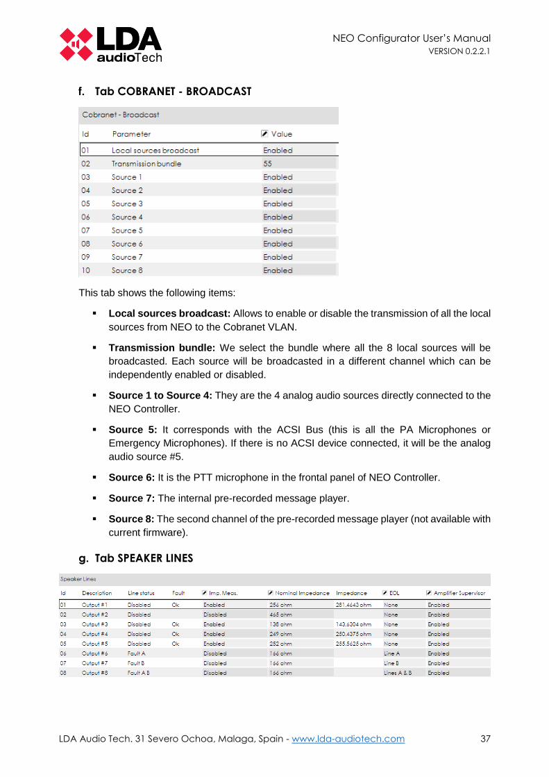
f. Tab COBRANET - BROADCAST
This tab shows the following items:
▪ Local sources broadcast: Allows to enable or disable the transmission of all the local
sources from NEO to the Cobranet VLAN.
▪ Transmission bundle: We select the bundle where all the 8 local sources will be
broadcasted. Each source will be broadcasted in a different channel which can be
independently enabled or disabled.
▪ Source 1 to Source 4: They are the 4 analog audio sources directly connected to the
NEO Controller.
▪ Source 5: It corresponds with the ACSI Bus (this is all the PA Microphones or
Emergency Microphones). If there is no ACSI device connected, it will be the analog
audio source #5.
▪ Source 6: It is the PTT microphone in the frontal panel of NEO Controller.
▪ Source 7: The internal pre-recorded message player.
▪ Source 8: The second channel of the pre-recorded message player (not available with
current firmware).
g. Tab SPEAKER LINES

NEO Configurator User’s Manual
VERSION 0.2.2.1
LDA Audio Tech. 31 Severo Ochoa, Malaga, Spain - www.lda-audiotech.com 38
This tab manages the supervision of the speaker lines and the internal amplifiers.
There are 2 modes of speaker lines supervision:
▪ EOL device
▪ Impedance Measurement
It is recommended to use only one mode of speaker line supervision.
ATTRIBUTES
▪ ID and DESCRIPTION: are the same as specified in the Tab POWER AMPLIFIER
OUTPUTS. They cannot be modified in this tab.
▪ LINE STATUS: It shows the supervision status if supervised with an EOL device.
Possible values:
o Disabled
o Ok
o Fault A
o Fault B
o Fault A B
▪ FAULT: It shows the supervision status if supervised with Impedance Measurement.
Possible values:
o Blank (in case Impedance Measurement supervision disabled)
o Ok
o CA: Open Circuit (measured value is above the nominal value + tolerance).
o CC: Short Circuit (measured value is below the nominal value + tolerance).
o Invalid (measured value is below the nominal value + tolerance)
NOTE: Default tolerance is 15%.
▪ IMP. MEAS. Enables or disables Impedance Measurement line supervision.
▪ NOMINAL IMPEDANCE: Shows the current Nominal Impendance set as reference
value.
▪ IMPEDANCE: Shows the current impendance of the line. There is an impedance
checkup every 45 seconds.
▪ EOL: Selects which output lines are to be supervised with EOL devices. Every
Amplifier Output has 2 output lines available. Options to choose:
o None (it disables EOL device line supervision)
o Line A
o Line B
o Lines A & B
▪ AMPLIFIER SUPERVISOR: Enables or disables the amplifier supervision. If the
amplifier supervision is enabled, NEO will report a fault in the amplifier and will be able
to switch over to the backup amplifier (if it is configured). By default this attribute is
disabled. For EN54-16 certified installations it should be switched to enabled.
NEO Configurator User’s Manual
VERSION 0.2.2.1
LDA Audio Tech. 31 Severo Ochoa, Malaga, Spain - www.lda-audiotech.com 39
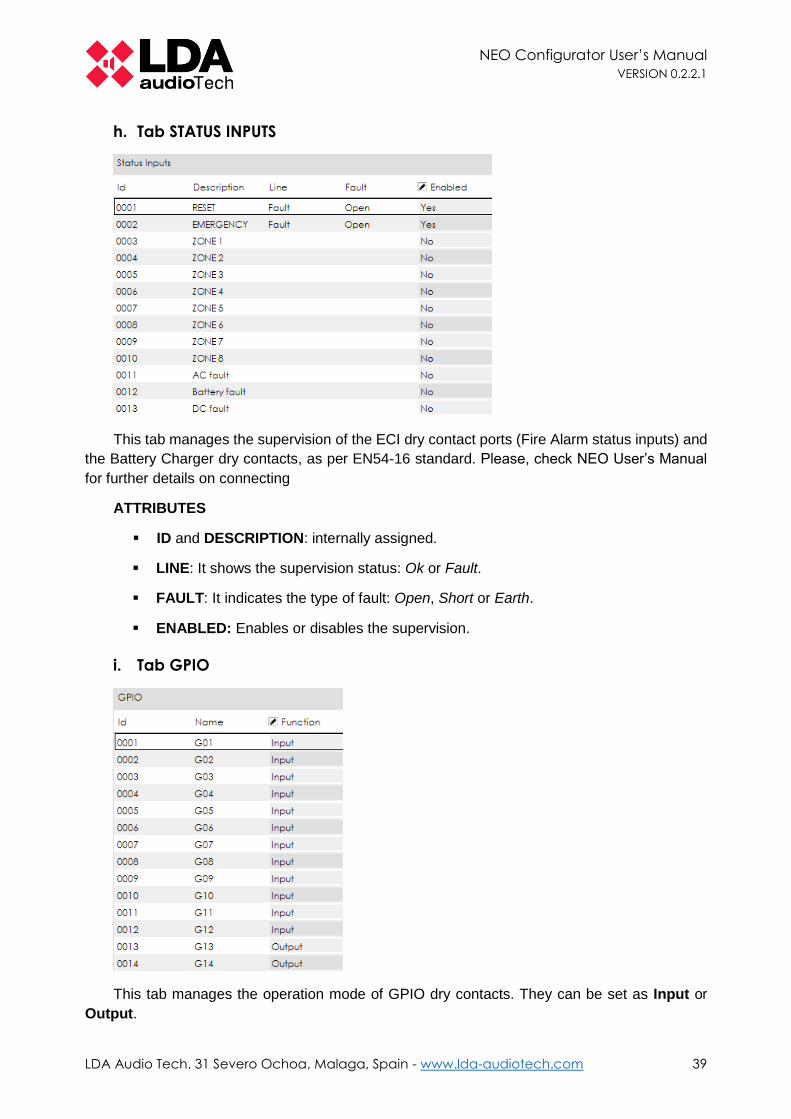
h. Tab STATUS INPUTS
This tab manages the supervision of the ECI dry contact ports (Fire Alarm status inputs) and
the Battery Charger dry contacts, as per EN54-16 standard. Please, check NEO User’s Manual
for further details on connecting
ATTRIBUTES
▪ ID and DESCRIPTION: internally assigned.
▪ LINE: It shows the supervision status: Ok or Fault.
▪ FAULT: It indicates the type of fault: Open, Short or Earth.
▪ ENABLED: Enables or disables the supervision.
i. Tab GPIO
This tab manages the operation mode of GPIO dry contacts. They can be set as Input or
Output.

NEO Configurator User’s Manual
VERSION 0.2.2.1
LDA Audio Tech. 31 Severo Ochoa, Malaga, Spain - www.lda-audiotech.com 40
j. Tab VLAN
NEO operates with 2 VLAN for transmitting Data and Audio (using Cobranet protocol). By
default the address of this VLAN is set as:
▪ VLAN Data: 1
▪ VLAN Audio: 2
The VLAN addresses can be modified to adapt to the network configuration from this tab.
k. Tab ACCESS CONTROL
This tab permits to specify and modify the PIN numbers that allow access to the different
levels of the menus within NEO touch screen. These access levels are described in NEO User’s
Manual.
By default, no PIN is requested to access every level. For EN54-16 installations a PIN should
be set for every access level.
l. Tab SCREENSAVER
NEO touch screen can be set to be dimmed and save energy after a period of 90 seconds
from the last action or message displayed in the touch screen.
In this tab, this option can be enabled and the brightness levels can be customized.
If the screensaver is disabled, the brightness level of the touch screen will always remain
100%.

NEO Configurator User’s Manual
VERSION 0.2.2.1
LDA Audio Tech. 31 Severo Ochoa, Malaga, Spain - www.lda-audiotech.com 41
m. Tab PTT CONFIG
By default, NEO frontal PTT microphone is supervised and don’t produce any ding-dong or
chime before broadcasting the voice. This is an EN54-16 requirement. Optionally, these settings
can be modified from this tab.
n. Tab ADVANCED
From this tab, NEO can be hard reset and load all the factory configurations. In order to do
so, just click on the button “Exe”.
By default, this reset will apply as well to the Ethernet configuration and thus the IP address
of the device will be set back to 192.168.0.3.
In order to save the Ethernet configuration (IP address) of the device, just switch the Value
attribute to “Don't reset Ethernet config”. The IP address, Network Mask and Gateway
parameters will be saved while the rest of the configuration will be reset to factory defaults.
4.1.4. Extensions
In the current version of NEO Configurator is not possible to configure NEO Extensions.
4.1.5. Accessories
In Accessories is where we can find PA Zone Controllers. Clicking on this device will show
the following tabs:
NOTE: The configuration tabs of this section will only be shown if your user profile is
Installer or Maintainer (see 2.2.3. Users preferences).

NEO Configurator User’s Manual
VERSION 0.2.2.1
LDA Audio Tech. 31 Severo Ochoa, Malaga, Spain - www.lda-audiotech.com 42
a. Tab STATE
This tab shows the current configuration of the PA Zone Controllers.
b. Tab GENERAL
In this tab you can add new PA Zone Controllers, change the Zone Id or delete existing PA Zone
Controllers. See section 3.2.4. PA Zone Controllers for detailed instructions.

NEO Configurator User’s Manual
VERSION 0.2.2.1
LDA Audio Tech. 31 Severo Ochoa, Malaga, Spain - www.lda-audiotech.com 43
4.2. Public Address System View
The Public Address System view shows the following function families:
▪ Sources
o Microphones
o Messages
o Audio Sources
▪ Matrix
▪ Zones
▪ Events
Events functions are described in 5. EVENTS.
4.2.1. Root
When you click over the root of the Public Address System view, you get these tabs:
NOTE: The configuration tabs of this section will only be shown if your user profile is
Installer, Maintainer or Operator (see 2.2.3. Users preferences).
a. Tab LOGS
The items of this tab are the following system logs:
▪ Public Address log file
▪ Device log file

NEO Configurator User’s Manual
VERSION 0.2.2.1
LDA Audio Tech. 31 Severo Ochoa, Malaga, Spain - www.lda-audiotech.com 44
The Device log file cannot be viewed from NEO Configurator, but it can be downloaded as
a BIN file so it can be sent to LDA Audio Tech for troubleshooting.
The operation of this tab is the same as described in System Devices view (see 4.1.1. Root).
b. Tab PRESETS
The items in this tab are NEO presets. A preset includes the configuration of the following
items:
▪ Input sources volume levels and equalization parameters.
▪ Zones volume levels and equalization parameters.
▪ Outputs volume levels and equalization parameters.
▪ Routing state of zones and sources.
Presets do not save other parameters like zoning, microphone settings, messages or events.
These presets can be loaded either from this tab or from the physical NEO touch. You can
also create (save) new presets from NEO Configurator or delete old presets.
4.2.2. Sources
The Sources function family is divided in 3 subfamilies: Microphones, Messages and Audio
Sources. Clicking directly on “Sources”, will show a list of all the tabs contained within every
subfamily. All these tabs are the same that are contained in every subfamily separately:

NEO Configurator User’s Manual
VERSION 0.2.2.1
LDA Audio Tech. 31 Severo Ochoa, Malaga, Spain - www.lda-audiotech.com 45
a. Tab MICROPHONES
The tab “View/Microphones” in Sources is the same as the tab “View/State” in Microphones.
The tab “Configuration/Microphones” in Sources is the same as the tab
“Configuration/General” in Microphones.
The configuration tab is the same as the view tab, but with editing capabilities:
ATTRIBUTES AND BUTTONS
▪ ID and NAME are internally assigned.
▪ DESCRIPTION can be edited.
▪ ACSI Dir/Prio: It indicates the direction of that microphone within the ACSI bus. This
direction also corresponds with the priority of this microphone. A NEO system can
contain a maximum of 8 ACSI devices, each of them with a unique ACSI
direction/priority.
NOTE: It is not possible to have a PA Microphone and an Emergency Microphone
with the same ACSI direction/priority, because they both use the same ACSI bus.
The ACSI direction/priority within NEO Configurator must correspond to the ACSI
direction/priority configured in the physical device (see MPS-8Z User’s Manual).
NOTE: If there is a PA Microphone with an ACSI direction/priority that does not
correspond to any MPS-8Z physically connected to NEO, it will appear as a
disconnected PA Microphone.
▪ STATE, TOKEN, FIRMWARE and UPDATE show additional info from the physical
PA Microphones when the system is live linked.
▪ ADD and REMOVE buttons are used to manually add or remove the PA Microphone
from the project (see 3.2.2. PA Microphones).
NOTE: It is not possible to change the ACSI Direction/Priority of a PA Microphone
from NEO Configurator after it has been added to the project.
NOTE 2: If you manually change the ACSI Direction/Priority from a physical MPS-
8Z, it will be disconnected from the NEO project: a new PA Microphone with the
new ACSI direction/priority should be added to NEO Configurator and the old one
(with the old ACSI direction/priority) should be removed.

NEO Configurator User’s Manual
VERSION 0.2.2.1
LDA Audio Tech. 31 Severo Ochoa, Malaga, Spain - www.lda-audiotech.com 46
b. Tab MESSAGES
The tab “View/Messages” in Sources is the same as the tab “View/State” in Messages.
The tab “Configuration/Messages” in Sources is the same as the tab “Configuration/Message
Transfer” in Messages.
The configuration tab is the same as the view tab, but with editing capabilities:
NOTE: The content of these tabs (i.e. the list of messages) can only be shown when the
system is live linked.
ATTRIBUTES AND BUTTONS
▪ ID is internally assigned.
▪ NAME and DESCRIPTION can be edited.
▪ SIZE and DURATION show additional info from the messages.
▪ ADD button: It is used to upload a new pre-recorded message to the NEO device. It
is possible to upload audio from 2 different file formats: WAV and MP3. In the case of
uploading an MP3 file, NEO Configurator will first convert it into WAV and then will
upload it to the NEO device.
▪ BACKUP button: It allows to download from NEO device to the computer the
message selected.
▪ REMOVE button: It removes the message in the NEO device.
NEO can store a maximum of 99 pre-recorded messages. The total capacity for all the
messages is 2GB (over 6 hours of audio). In the lower part of NEO Configurator window is shown
the total storage capacity used and available for pre-recorded messages:

NEO Configurator User’s Manual
VERSION 0.2.2.1
LDA Audio Tech. 31 Severo Ochoa, Malaga, Spain - www.lda-audiotech.com 47
c. Tab AUDIO SOURCES
The tab “View/Audio Sources” in Sources is the same as the tab “View/State” in Audio
Sources.
The tab “Configuration/Audio Sources” in Sources is the same as the tab
“Configuration/Audio Sources” in Audio Sources.
The configuration tab is the same as the view tab, but with editing capabilities:
This tab shows all the local analog audio sources (see c. Tab AUDIO INPUTS) as well as
the remote sources (see e. Tab COBRANET - SOURCES).
The name and description are the same that are shown in the System Devices tabs: c. Tab
AUDIO INPUTS and e. Tab COBRANET - SOURCES.
4.2.3. Matrix
The Matrix function family includes the following tabs:
The Configuration/Routing tab is the same as the View/State tab, but with editing capabilities:

NEO Configurator User’s Manual
VERSION 0.2.2.1
LDA Audio Tech. 31 Severo Ochoa, Malaga, Spain - www.lda-audiotech.com 48
This tabs show all the system zones and the source that is routed in every zone. The source
can be changed also from here. Only analogue audio sources and remote sources can be
selected.
4.2.4. Zones
The Zones function family includes the following tabs:
The Configuration/Zones tab is the same as the View/State tab, but with editing capabilities:
Every zone is a group of physical outputs. By default, 1 output = 1 zone, but this can be modified
as per the project requirement within this tab.
ATTRIBUTES AND BUTTONS
▪ ID is internally assigned.
▪ NAME and DESCRIPTION can be edited.
▪ VOLUME and MUTE: These parameters are modified independently from the volume
level of the outputs that belong to a zone. These adjustments affect to all the outputs
within the zone as a group.
▪ OVERRIDE shows whether the override function associated to that zone is activated.
Override are usually activated from an event (see chapter 5. EVENTS).
▪ SOURCE shows the current audio source routed to that zone. The routing state can
be modified from 4.2.3. Matrix function family.
▪ ADD and REMOVE buttons: They allow to add or remove zones in the system.

NEO Configurator User’s Manual
VERSION 0.2.2.1
LDA Audio Tech. 31 Severo Ochoa, Malaga, Spain - www.lda-audiotech.com 49
▪ CHANNELS button opens a window to configure the Audio Outputs within a zone:
Several Audio Outputs can be added to one zone, so that a group of outputs will
operate as a single zone. Every Audio Output can only be included in one zone; it is
not possible to include the same Audio Output in many zones.
ADD AN OUTPUT TO THE ZONE:
1. Select the Audio Output from the lower “Amplifier Channels” panel.
2. Click on “Add”.
3. Click on “Apply” to save the changes.
NOTE: If you add an Audio Output which was previously assigned to a different
zone, that output will be removed from that zone.
REMOVE AN OUTPUT FROM THE ZONE:
1. Select the Audio Output from the upper “Zone #000X - Amplifier Channels” panel.
2. Click on “Delete”.
3. Click on “Apply” to save the changes.
NOTE: When you remove an Audio Output which was already assigned to the
zone, that output will become unassigned and will not belong to any zone. In order
to ensure that that audio channel can be used, make sure that the unassigned
output is readded to another zone.

NEO Configurator User’s Manual
VERSION 0.2.2.1
LDA Audio Tech. 31 Severo Ochoa, Malaga, Spain - www.lda-audiotech.com 50
▪ OVERRIDE button opens a window to configure the Override Outputs within a zone:
The Override Outputs in NEO can be launched under 2 conditions:
a. When NEO receives a dry contact in one of the Status Inputs for the Fire Alarm
(ECI 1-8 or Z1-Z8).
b. When it is launched by an event (see chapter 5. EVENTS).
In this button can be configured what Override Outputs are activated when NEO
receives the Fire Alarm dry contact in a specific zone (case a).
The assignation of Override Outputs with a specific zone can be made independently
of the Audio Outputs assigned to that same zone. For example, Zone 3 can have Audio
Outputs #3, #5 and #6 while at the same time have Override Outputs #2, #3, #4, #5
and #6.
It is also possible to have a zone with no Override Output or a zone only with Override
Outputs and no Audio Output.
Every Override Output can only be included in one zone. It is not possible to include
the same Override Output in many zones.
ADD AN OUTPUT TO THE ZONE:
1. Select the override output from the lower “Override” panel.
2. Click on “Add”.

NEO Configurator User’s Manual
VERSION 0.2.2.1
LDA Audio Tech. 31 Severo Ochoa, Malaga, Spain - www.lda-audiotech.com 51
3. Click on “Apply” to save the changes.
NOTE: If you add an Override Output which was previously assigned to a different
zone, that output will be removed from that zone.
REMOVE AN OUTPUT FROM THE ZONE:
1. Select the output from the upper “Zone #000X - Override” panel.
2. Click on “Delete”.
3. Click on “Apply” to save the changes.
NOTE: When you remove an Override Output which was already assigned to the
zone, that Override Output will become unassigned and will not belong to any
zone.

NEO Configurator User’s Manual
VERSION 0.2.2.1
LDA Audio Tech. 31 Severo Ochoa, Malaga, Spain - www.lda-audiotech.com 52
4.3. Voice Alarm System View
The Public Address System view shows the following function families:
▪ Sources
o E Microphones
o Messages
o Audio Sources
▪ Matrix
▪ Zones
▪ Events
Events functions are described in chapter 5. EVENTS.
4.3.1. Root
When you click over the root of the Voice Alarm System view, you get these tabs:
NOTE: The configuration tabs of this section will only be shown if your user profile is
Installer (see 2.2.3. Users preferences).
a. Tab LOGS

NEO Configurator User’s Manual
VERSION 0.2.2.1
LDA Audio Tech. 31 Severo Ochoa, Malaga, Spain - www.lda-audiotech.com 53
The items of this tab are the following system logs:
▪ Emergency log
▪ Fault log
▪ Disarmed log
The operation of this tab is the same as described in System Devices view (see 4.1.1. Root).
b. Tab GENERAL
This tab allows to enable or disable the following functionalities:
▪ PA Mics can be used in VA state.
▪ PA Zones can be used in VA state: it allows to route PA sources to the zones while
the device is in VA state.
c. Tab PRESETS
This tab is exactly the same that appears in Public Address System view (see b. Tab
PRESETS in 4.2.1. Root).
4.3.2. Sources
The Sources function family is divided in 3 subfamilies: E Microphones, Messages and
Microphones. Clicking directly on “Sources”, will show a list of all the tabs contained within every
subfamily, except the Message Transfer tab.. All these tabs are the same that are contained in
every subfamily separately:

NEO Configurator User’s Manual
VERSION 0.2.2.1
LDA Audio Tech. 31 Severo Ochoa, Malaga, Spain - www.lda-audiotech.com 54
a. Tab E MICROPHONES
The tab “View/EMicrophones” in Sources is the same as the tab “View/State” in
EMicrophones.
The tab “Configuration/EMicrophones” in Sources is the same as the tab
“Configuration/General” in EMicrophones.
The configuration tab is the same as the view tab, but with editing capabilities:
ATTRIBUTES AND BUTTONS
▪ ID and NAME are internally assigned.
▪ DESCRIPTION can be edited.
▪ ACSI Dir/Prio: It indicates the direction of that microphone within the ACSI bus. This
direction also corresponds with the priority of this E Microphone. A NEO system can
contain a maximum of 8 ACSI devices, each of them with a unique ACSI
direction/priority.
NOTE: It is not possible to have an E Microphone and a PA Microphone with the
same ACSI direction/priority, because they both use the same ACSI bus.
The ACSI direction/priority within NEO Configurator must correspond to the ACSI
direction/priority configured in the physical device (see VAP-1 User’s Manual).
NOTE: If there is an E Microphone with an ACSI direction/priority that does not
correspond to any MPS-8Z physically connected to NEO, it will appear as a
disconnected E Microphone.
▪ STATE, TOKEN, FIRMWARE and UPDATE show additional info from the physical
E Microphones when the system is live linked.
▪ ADD and REMOVE buttons are used to manually add or remove the E Microphone
from the project (see 3.2.2. PA Microphones).
NOTE: It is not possible to change the ACSI Direction/Priority of a E Microphone
from NEO Configurator after it has been added to the project.
NOTE 2: If you manually change the ACSI Direction/Priority from a physical VAP-
1, it will be disconnected from the NEO project: a new E Microphone with the new
ACSI direction/priority should be added to NEO Configurator and the old one (with
the old ACSI direction/priority) should be removed.

NEO Configurator User’s Manual
VERSION 0.2.2.1
LDA Audio Tech. 31 Severo Ochoa, Malaga, Spain - www.lda-audiotech.com 55
b. Tab MESSAGES
The tab “View/Messages” in Sources is the same as the tab “View/State” in Messages.
The tab “Configuration/Messages” in Sources is the same as the tab “Configuration/General”
in Messages.
The configuration tab is the same as the view tab, but with editing capabilities:
NOTE: The content of these tabs (i.e. the list of messages) can only be shown when the
system is live linked.
ATTRIBUTES AND BUTTONS
▪ ID can be either:
o EVAC for the Evacuation Message.
o ALERT for the Alert Message.
▪ NAME and DESCRIPTION can be edited.
▪ SIZE and DURATION show additional info from the messages.
▪ BACKUP button: It allows to download from NEO device to the computer the
message selected.
▪ EDIT button opens the following window:
This windows allows to define the EVAC (or ALERT) message in NEO. It must be
selected from one of the previously uploaded messages. In c. Tab MESSAGE
TRANSFER is explained how to upload new messages.

NEO Configurator User’s Manual
VERSION 0.2.2.1
LDA Audio Tech. 31 Severo Ochoa, Malaga, Spain - www.lda-audiotech.com 56
▪ BACKUP button: It allows to download from NEO device to the computer the
message selected.
NOTE: EVAC or ALERT messages can never be deleted because they are essential for
the basic operation of NEO during an emergency. These 2 emergency message types
are mandatory as per EN54-16.
c. Tab MESSAGE TRANSFER
In the “Messages” subfamily there is an additional tab that does not appears when clicking
directly on “Sources”:
This tab is exactly the same that appears in the Public Address System view (see b. Tab
MESSAGES in 4.2.2. Sources).
It can be used as shortcut to manage all the pre-recorded messages in NEO before or after
assign them as EVAC or ALERT message in the tab “General”.
d. Tab MICROPHONES
This tab is exactly the same that appears in the Public Address System view (see a. Tab
MICROPHONES in 4.2.2. Sources).
4.3.3. Matrix
This function family is practically the same as explained in Public Address System view (see
4.2.3. Matrix). The only difference is a new attribute called “State”:

NEO Configurator User’s Manual
VERSION 0.2.2.1
LDA Audio Tech. 31 Severo Ochoa, Malaga, Spain - www.lda-audiotech.com 57
The attribute “State” can have the following values:
o Emergency: when that zone is in emergency mode (i.e. it is broadcasting an EVAC/
ALERT message or an Emergency Microphone).
o Fault: when a speaker line or amplifier within that zone reports a fault (see g. Tab
SPEAKER LINES).
o Disarmed: when that zone has been manually disarmed.
o Quiesence: when none of the other states is active (i.e. that zone is operating normally
in PA mode).
4.3.4. Zones
This function family is practically the same as explained in Public Address System view (see
4.2.4. Zones). The only difference are 2 new attributes, “Disarmed” and “State”:
The attribute “Disarmed” is used to manually disarm or rearm a specific zone.
The attribute “State” can have the following values:
o Emergency: when that zone is in emergency mode (i.e. it is broadcasting an EVAC/
ALERT message or an Emergency Microphone).
o Fault: when a speaker line or amplifier within that zone reports a fault (see g. Tab
SPEAKER LINES).
o Disarmed: when that zone has been manually disarmed.
o Quiesence: when none of the other states is active (i.e. that zone is operating normally
in PA mode).
Top Related