


Languages
Pages
Legal


User Manual Contents
1. Introduction
In-Cab Decals
2. Application Recommendations
3. Safe Working Load
4. Safety Related Measures
5. Operating Instructions
a. Hydraulic Coupler
b. Manual Coupler
6. Maintenance Guide
7. Parts List
8. Removing Parts from QC Model
9. Troubleshooting Guide
10. Warranty

1. Introduction
Thank you for purchasing a Geith Quick Coupler. By doing so
you have chosen a tried and tested system which we trust will
provide you with many years of trouble free performance. In
common with all Geith attachments it is manufactured to the
highest quality and backed up by the Geith commitment to
service that cannot be beaten.
Only proficiently trained and skilled
personnel should install and operate the Quick
Coupler. To help ensure Safety For All Please
ensure that you take the time to read this manual
fully and carefully.
It is vitally important to the correct
operation and safe work practices that all
users/operators are familiar with and fully understand all
aspects of the information contained in this publication.
All operators must be properly trained in the use of the
specific model of quick hitch intending to be used.
It is the responsibility of the machine owner to ensure
only competent operators use the quick coupler.
Failure to operate equipment correctly can result in
serious injury or death.

In-cab Decals
Safety Decal stickers are supplied with this Quick Coupler.
They must be fitted onto the inside of the cab window where
they can easily be seen.

2. Application Recommendations
The Geith range of Hydraulic Excavator Quick Couplers is
designed for use with all makes of Excavators, combined with a
wide range of attachments, to suit a wide range of work
applications. Owners and operators please take note however
that all possible applications, operations and uses for the quick
coupler cannot be predicted or anticipated. It is therefore the
responsibility of the owner and operators of the quick coupler to
ensure that the quick coupler is used and maintained in a safe
and appropriate manner that will not cause damage to or make
unsafe in any way, the operation of the quick coupler or
equipment being used.
Safe Use
Pin grabber type couplers are primarily
designed to withstand loading situations
that direct and transmit the working
forces of the excavator and attachment
through key load points on the quick coupler (see Fig. 1).
Failure by the owner or operator to use the coupler appropriately
may result in premature wear and tear of the coupler and may
lead to premature failure.
Fig. 1

Operations that are compatible with quick
couplers are general excavating tasks such as
digging, handling using grabs/grapples (use
suitable 2 pin adapter plates at all times) and
also crushing and breaking of rock/debris.
When used in accordance with the
manufacturers instructions the use of rock
breakers is recommended for use with the Geith
Quick Coupler.
On no account should the rock breaker be
used as a leveraging tool (see Fig. 2) as this not
only damages the rock breaker but will also
lead to damage of the quick coupler. In the
event of sustained use of this type of equipment
and where change of attachments is infrequent,
it may be more appropriate to temporarily remove the quick
coupler from the excavator for the duration of the sustained task
which in the longer term will reduce maintenance costs and in
some instances also improve the performance and productivity
of the attachment.
It should be appreciated that as with all equipment, the
more severe and arduous the application, the greater the wear
and tear that will be experienced by the quick coupler and hence
the expected working life of the coupler will vary. Used and
maintained correctly and safely, the Geith Auto-Lock Coupler
will give many years of unbeatable performance across a wide
range of tasks and applications.
Fig. 2

All attachments to be connected to
the Quick Coupler MUST be
connected using the two attachment
pins (see fig. 3). On no account must
any attachment be connected using
only one of the attachment pins.
Typical examples where this might
occur are with some types of material
handling grab and piling hammers. In
these cases a two pin adapter bracket
designed for the purpose must be
used. See (Fig. 3) for example.
To increase the life span of the quick hitch, callipers should be
fitted to pick up the desired dipper width of the attachments
where possible. This will prevent any sideways movement and
subsequent wear issues with the hitch or its internal parts.
Other operations that may have a negative affect on the coupler
are:
Extensive face shovelling applications
Post driving
It is the responsibility of the owner and or the operator to
assess each task and determine the safest procedure to be
followed taking account of the personnel and the equipment
being used.
Fig. 3

A
Bucket
Drill
Stump
Jaw Bu
Exbe
Civi
Angle tilt
t & Klamps
ing Rigs
p Grinders
cket
xamples of e used with
l and Const
Digging bu
Adapter Br
Compac
High Capaci
G‐ Prof
equipment Geith Quic
truction wo
uckets G
racket R
ctors Com
ity bucket
file Trap
t that can ck Hitches
rk
Grading Buck
Riddle Bucke
mpactor Whe
Pallet For
pezoidal Buc
kets
et
eels
rks
cket

Demolition and Quarry work
Rock Breaker Ripper Hook
Crushers RF & XF Buckets
Grapple Shears
Examples of equipment that can be used with Geith Quick Hitches

Rail work
Flail Ballast Broom Rail Lifting Beam
Rock Wheel Sleeper Grab Vibratory hammer
Examples of equipment that can be used with Geith Quick Hitches

Please take note of and be aware of the Safe Working Load for
the Coupler integrated lift eye that is
marked on the Information plate
fixed to the Quick Coupler body.
This is the limiting lift capacity when
using a coupler for lifting.
Before carrying out a lift operation
using the coupler integrated lift eye,
please remove any attachment that is
connected to the Quick Coupler.
Using the suggested operating method as shown, the lift eye
should only be used for lifting if the excavator to which it is
fitted is rated and equipped for lifting duties as required by
lifting equipment regulations and has a current report of
thorough examination. Be aware of the maximum machine lift
capacity for your machine configuration and for the lift cycle
and envelope of movement you are about to undertake. The
rated lift capacity of the quick coupler may be less than the rated
capacity of the excavator or vice versa. It is important that the
lower of the two values is used to determine the rated lift
capacity of the combination.
If necessary, make allowances for the weight of the Quick
Coupler that is fitted to the excavator (the weight of the Quick
Coupler can be found on the Information Plate fixed to the
Quick Coupler body and in this operator manual. See Fig. 4).
Ensure all personnel and unnecessary equipment is moved clear
of the operation site and cordon off the area to prevent
encroachment during the lifting operation.
3. Safe Working Load
Fig. 4

Use only the specified lift eye position for lifting slung loads.
Never use the attachment pin connection hooks of the Quick
Coupler for lifting slung loads.
Lifting with a quick coupler should always be carried out with
the quick coupler vertical so that the load and lifting accessories
can hang free without contacting the coupler body. Failure to
follow the suggested lifting procedure may result in equipment
failure and the loss of the supported load.

4. Safety Related Measures
The Geith Auto-Lock range of Quick Hitches/Couplers have
been developed with safety of use as the number one priority.
Since our first Auto-lock coupler, launched in 2001 we have
continually improved on the performance of the system, making
it one of the most reliable and respected products of its kind on
the market today.
The following information provides Safety
Notices and information relating to the Safe
Installation and use of the Geith Auto-Lock
CLAW quick coupler. It is not a conclusive
document and recommendations contained
within the document should be considered in
conjunction with any additional safe working
practices and inspection requirements that may
apply, either due to specific company
requirements and regulations or on site best
practice instructions.

Installation of the Geith Auto-Lock coupler should be
carried out by suitable trained and qualified personnel
only. Failure to comply with this requirement may result in
a risk to safety.
Only use the installation kit supplied with the Quick hitch
to ensure that the quick hitch operates as intended and in a
safe manner.
Should the Quick Coupler be installed
with a non Geith control system, you
must ensure that the Quick Coupler
operates as per Geith recommended
instructions.
Always wear appropriate PPE clothing
and equipment for working with
hydraulic equipment.
When installing the quick coupler you
must use only suitable approved/certified
lifting equipment. Please refer to Quick
Coupler CE badge for guidance weights
on each model.

Exercise extreme caution when carrying out
maintenance procedures on the Quick Coupler,
particularly when working with pressurized
fluids such as hydraulic oil.
Before commencing any examination or
maintenance work.
Always ensure the coupler and attachment
is supported in a stable position.
All power to the coupler and machine is cut
(in order to prevent any unintentional or
unexpected movement of coupler or attachment).
Be aware of residual oil pressure in the
hydraulic system when loosening or
removing any hose or pipe connections.
Always depressurize the system before
starting maintenance work on the quick
coupler.
Never search for oil leaks with bare hands as
pressurized oil can penetrate the skin and
cause serious health risk.

There is the potential for great risk to safety while
operating machinery and equipment. Extreme
care must be taken when operating the Auto-
Lock Coupler and attachments in proximity to
ground workers. Ensure that there are no
personnel within the operating radius of the
machine while carrying out work practices.
Never pass an attachment over the heads
of persons.
When working with Hydraulic Oil, every
precaution should be taken to prevent oil spillage
on the equipment or ground. Oil can seep into
drains, and waterways through run off systems or
through ground soakage causing danger to people
and the environment. Oil spillage on equipment
or ground can cause risk of slippage which may
lead to serious or fatal injury.
Use collection vessels to collect and retain any oil being
released from the system. Dispose of unwanted oil and oily
rags/materials safely as per Environmental regulations that
apply.
The maintenance of quick couplers is critical to the
ongoing safe operation of the equipment and should be carried
out by competent persons only. Inspections should be carried
out on a scheduled basis to assist early identification of issues
that may develop into more serious problems.

5.a Operating Instruction (Hydraulic Coupler)
CONNECTING AN ATTACHMENT
1. On the Quick Coupler operation control panel press the
system ‘ON’ (0 denotes OFF and I denotes ON) button and then
press button ‘A’. Note: Button ‘A’ must be pressed within five
seconds of pressing the ‘ON’ button or the system will not
operate. If this occurs press the ‘ON’ / ’OFF’ button to the OFF
position to reset, then start the sequence again. See fig. 5 and
fig. 6.
When button ‘A’ is pressed outstroke the bucket ram fully to
crowd the quick Coupler. This will enable the auto lock to open
fully.
Fig. 5 Fig. 6

. When the Auto-Lock is open, crowd the Quick Coupler to the
open digging position and lower the Quick Coupler hooks down
onto the front pin. Crowd the Quick Coupler around until the
Quick Coupler contacts the bucket back pin and raise the bucket
off the ground while continuing to crowd the Quick Coupler
fully inwards to the closed position. See fig. 7 and fig. 8.
7
3. With the Quick Coupler crowded fully inwards press the
ON/OFF button on the control panel to the OFF position while
continuing to crowd the Quick Coupler
inwards. The Auto-Lock will close
around the attachment pin (this will be
visible from the operator position in
the cab.)
While the rear pin engaging wedge will
lock the back pin into position. See fig. 9.
Fig. 7 Fig. 8

At this point it is most important to crowd out the Quick
Hitch and shake vigorously and/or bump the attachment off
the ground to ensure the attachment is secured to the Quick
Coupler. See fig. 10 or fig. 11. If the Auto-Lock is not visibly
in position in front of the attachment pin then the Quick
Coupler must not be operated to carry out work. The
excavator should be switched off and the Quick Coupler
should be examined for signs of damage. Contact your
supplier, or Geith International immediately should you
require assistance.
If the Auto Lock is engaged and the attachment is secured safely
to the Quick Coupler it is safe to operate the attachment to carry
out the intended work.
Fig. 9 Fig. 10 Fig. 11

RELEASING AN ATTACHMENT:
1. With Quick Coupler and attachment at ground level, position
attachment in a curled position with hooks pointing upwards as
per fig. 12, with the pressure built up in the machine bucket
digging/crowd cylinder.
2. Ensure that all personnel are standing clear of quick hitch and
machine swing radius.
3. To enable the Quick Coupler Control system to operate
Crowd the Quick Coupler fully inwards so that a
pressure is built up in the Quick Coupler Hydraulic
control system from the outstroke of the machine
bucket digging/crowd cylinder.
When the Quick Coupler is fully crowded inwards,
press the control panel ‘ON/OFF’ switch to the ‘ON’
position. (See fig. 13.)
Then press the button on the control panel marked
‘A’ (See fig. 14) while continuing to operate the
crowd lever to maintain the Quick Coupler in the
crowded in position.
Note: Button ‘A’ must be pressed within five
seconds of pressing the ‘ON’ button or the system
will not operate.
Safety Lock
in position
Fig. 12

If this occurs press the ‘ON’ / ‘OFF’ button to the
OFF position to reset. Then start the sequence again.
See fig. 13. and fig. 14.
Continue to crowd the Quick Coupler inwards until
the AutoLock has fully opened.
4. Lower the attachment to the ground and release it from the
Quick Coupler by crowding the Quick Coupler outwards away
from attachment pins. See fig.15 and fig. 16.
5. You should now be free to raise Quick Coupler up and clear
of attachment ready to pick up other attachment as necessary.
Fig. 13 Fig. 14
Fig. 15 Fig. 16

5.b Operating Instruction (Manual Coupler)
CONNECTING AN ATTACHMENT:
1. When the Auto-Lock is open, crowd the Quick Coupler to
the open digging position and lower the Quick Coupler
hooks down onto the front pin. Crowd the Quick Coupler
around until the Quick Coupler contacts the bucket back
pin and raise the bucket off the ground while continuing to
crowd the Quick Coupler fully inwards to the closed
position. See fig. 17 and fig. 18.
2. Attach the drive bar supplied with the Manual Auto-Lock
Quick Coupler to the cylinder drive shaft at the back of the
engaging plate and proceed to tighten. At initial tightening
the Auto-Lock clasp will close over the front pin thus
securing the attachment to the Quick- Coupler. Continuous
tightening of the bar will engage the link pin engaging
plate under the attachment link pin.
Fig. 17 Fig. 18

3. Continue to tighten the drive bar until no further tightening
is possible. See fig. 19. Warning: Do not extend drive bar
(by use of extension tube etc) when tightening as over-
tightening may result in difficulty releasing the attachment,
or damage to the mechanism.
4. Remove the drive bar and store in excavator cab for reuse
when next changing attachment.
At this point it is most important to crowd out the Quick
Coupler and shake the attachment vigorously and / or carry
out a bump test to ensure the attachment is secured to the
Quick Coupler. See fig. 21 or fig. 22. If the Auto-Lock (fig.
20) is not visibly in position in front of the attachment pin
then the Quick Coupler must not be operated to carry out
work. The excavator should be switched off and the Quick
Coupler should be examined for signs of damage. Contact
your supplier, or Geith International immediately should
you require assistance.
If the Auto Lock is engaged and the attachment is secured safely
to the Quick Coupler it is safe to operate the attachment to carry
out the intended work.
Fig. 20 Fig. 21 Fig. 22
Fig. 19
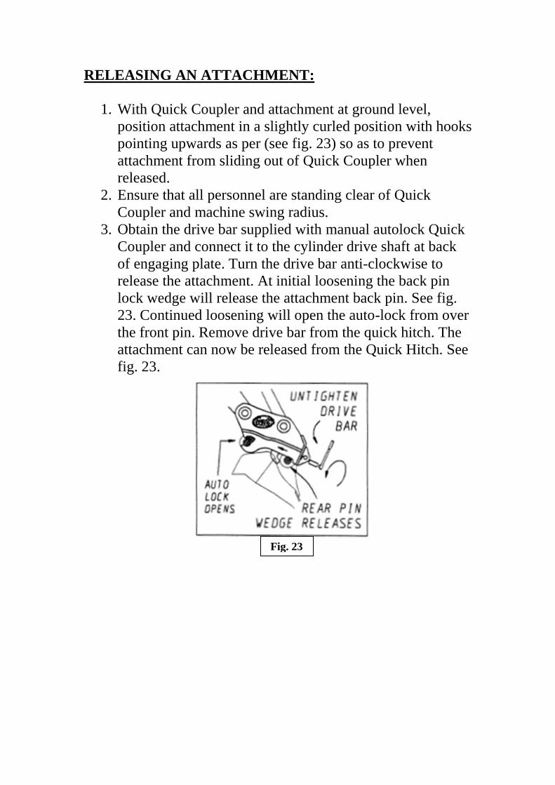
RELEASING AN ATTACHMENT:
1. With Quick Coupler and attachment at ground level,
position attachment in a slightly curled position with hooks
pointing upwards as per (see fig. 23) so as to prevent
attachment from sliding out of Quick Coupler when
released.
2. Ensure that all personnel are standing clear of Quick
Coupler and machine swing radius.
3. Obtain the drive bar supplied with manual autolock Quick
Coupler and connect it to the cylinder drive shaft at back
of engaging plate. Turn the drive bar anti-clockwise to
release the attachment. At initial loosening the back pin
lock wedge will release the attachment back pin. See fig.
23. Continued loosening will open the auto-lock from over
the front pin. Remove drive bar from the quick hitch. The
attachment can now be released from the Quick Hitch. See
fig. 23.
Fig. 23

4. Lower the attachment to the ground and release it from the
Quick Hitch by crowding the Quick Coupler outwards
away from attachment pins. See fig. 25.
5. You should now be free to raise Quick Coupler up and
clear of attachment ready to pick up other attachment as
necessary.
Please Note: when changing a Hydraulic Coupler to a
Manual Coupler please refer to section 7 of the user manual
for instruction on changing out parts.
Fig. 24 Fig. 25
6. Maintenance Guide
NOTE:
The effective maintenance of a Quick Coupler is critical in
ensuring that the Quick Coupler is working in the correct
manner and prevents degradation of the Quick Coupler under
normal wear patterns. Ensure any latent pressure in the
hydraulic system is released and machine is turned off before
any work is carried out on the Quick Coupler.
1. Routine Inspection/Maintenance Checks
Construction attachments operate in difficult and severe
environment where there can be unpredictable loading situations
applied to the equipment many times during the day. On rare
occasions, over time, ongoing exposure to such a work cycle
may lead to changes in the equipment structure and
performance. The equipment will be subjected to high stress and
fatigue loading situations which may initiate and develop
potential fault situations such as cracking, bending and
deterioration of components. These faults if undetected may
eventually lead to sudden and possibly dangerous failures.
Maintenance work must be carried out by competent
personnel in accordance to manufacturer’s guidelines.
Never use bare hands to look for hydraulic fluid leaks.
Ensure that maintenance checks are being carried out to the
correct procedures and are followed so that there is no risk to
anyone completing the maintenance checks or in the
immediate area.

2. General Inspection and Maintenance Equipment
required
- Measuring equipment – measuring tape, vernier callipers.
- Cleaning equipment – Brush, cloths, de-greaser.
- Straight edge.
- Hose Swaging equipment.
- Selection of hand tools (spanners, vice grips, screw driver
set, hammers etc).
3. Scheduled Inspections – When and what to check
Recommended minimum maintenance checks:
- After installation – inspect hose connections after 15
minutes of work as they could loosen after machine has
heated up.
- Structure – inspect for weld cracking, damage, excess wear
to structure and parts.
- Moving components – fit up, looseness, linkages,
clearances, sticking/jamming.
- Hydraulics – hose wear/leaks, joints damage/leaks,
solenoid valve (control) for leaks of cable damage,
cylinder (signs of wear on housing) leaks.
- Electrical – control box function and general condition.
- Springs – condition, presence.
- Fit up of coupler to machine – wear in bushings.
- Fit up of coupler to attachments – correct attachment .
- Lift eye – wear or damage.
- Check for cylinder condition (cylinder
leakage, rod damage, holding capacity, pressure loss etc).

4. Daily checks
Before starting work with the excavator the operator should
carry out a thorough visual inspection of the quick coupler:
- Remove any dirt and debris from the coupler, especially
around the internal mechanisms (hydraulic cylinder,
linkage, spring mechanism).
Check coupler pin pick up
hooks to ensure there is no build up
of dirt.
- Check coupler structure for signs of
damage, especially the load bearing hooks
and hydraulic cylinder.
- Check all fixing points (bolts, nuts, clips,
pins etc) for signs of wear or damage.
- Check all hydraulic hoses and connections
for evidence of oil leakage.
- The quick coupler should not be operated until all issues
are repaired or replaced as necessary.

5. Weekly Inspection
- Clean coupler and visually inspect the structure to
ensure it is free from defects and signs of excessive
wear.
- Visually check the hydraulic cylinder for leakages at pipes
and rod seal. Replace if necessary.
- Internal piston seals can wear over time and are more
difficult to check for performance degradation. One
method of checking these seals is as follows:
Cylinder Test
o Is carried out in a secure,
controlled area.
o Connect an attachment to the
coupler and open or curl the
coupler back to load the
hydraulic cylinder with the
weight of the attachment.
o Lower the attachment to within 300mm from ground
level.
o Switch off the machine and leave machine at rest for a
nominal period of 10 minutes, while observing any
change to the position of the quick coupler engaging
plate. If the position is seen to drift inwards
(hydraulic cylinder is in-stroking) then it is an
indication of potential loss of oil over the internal piston
seals in the cylinder or a potential problem with the
cylinder check valve failing to sufficiently retain the oil in
the cylinder.
WARNING!

o Should drifting occur:
Outstroke Quick Coupler cylinder to engage the
attachment pins.
Lower attachment and coupler on to the ground and
Switch off machine.
Remove the hose from quick coupler cylinder port
‘V2’ and plug the removed hose to prevent loss of oil.
Clean away oil residue from cylinder port.
Start machine and repeat the above procedure.
Observe the cylinder port for further or continued oil
flow/seep.
If oil flow is evident then there is an indication that the
piston seals need replacement.
Replace the piston seals and repeat the test procedure
once more.
If there is continued drift then the cylinder check valve
should be replaced and again a re-test should be carried
out to confirm resolution of the problem and the
cylinder functions correctly.
- Review any previous maintenance history on
the product
- Look for evidence of previous repair or re-
work
WARNING!

7. P
art
s L
ist

8. Removing Parts from QC Model
Before you start you will need the follow tools to complete
the procedure
1. Flat-head Screw driver
2. Large bolt/punch (20mm or 10mm)
3. Hammer
4. Punch tool (check Quick Coupler for correct size)
5. 2 X Wrenches (check Quick Coupler for correct size)
1. Partially curl in the Quick Coupler (link pin lower than dipper
pin). This is for ease of removing the small roll pin.
2. Instroke the coupler cylinder.
3. Using the punch tool and hammer remove the safety clasp
roll pin.
4. Place the Coupler on the ground.

5. Remove machine link pins from the Quick Coupler.
6. Lift the machine linkage out of the way by retracting the
machine bucket cylinder.
7. Turn off the machine.
8. Remove the hoses from the cylinder.
9. Tighten the spring retaining bolt until you are able to
remove it. Note: make sure the flats of the spring retainers
are in line with retaining brackets so that it will fit into
place.

10. Remove the Spring assembly.
11. Remove the safety clasp main pivot pin.
12. Remove the safety Clasp from the Quick Coupler.
13. Using the punch tool and hammer to remove the stopper
roll pins and engaging plate retaining roll pins.

14. Using flat head screw driver remove the rubber bungs.
15. Remove the cylinder by rotating it fully upright (1)
before lifting out (2).
16. To fit parts repeat steps in reverse.
2. 1.

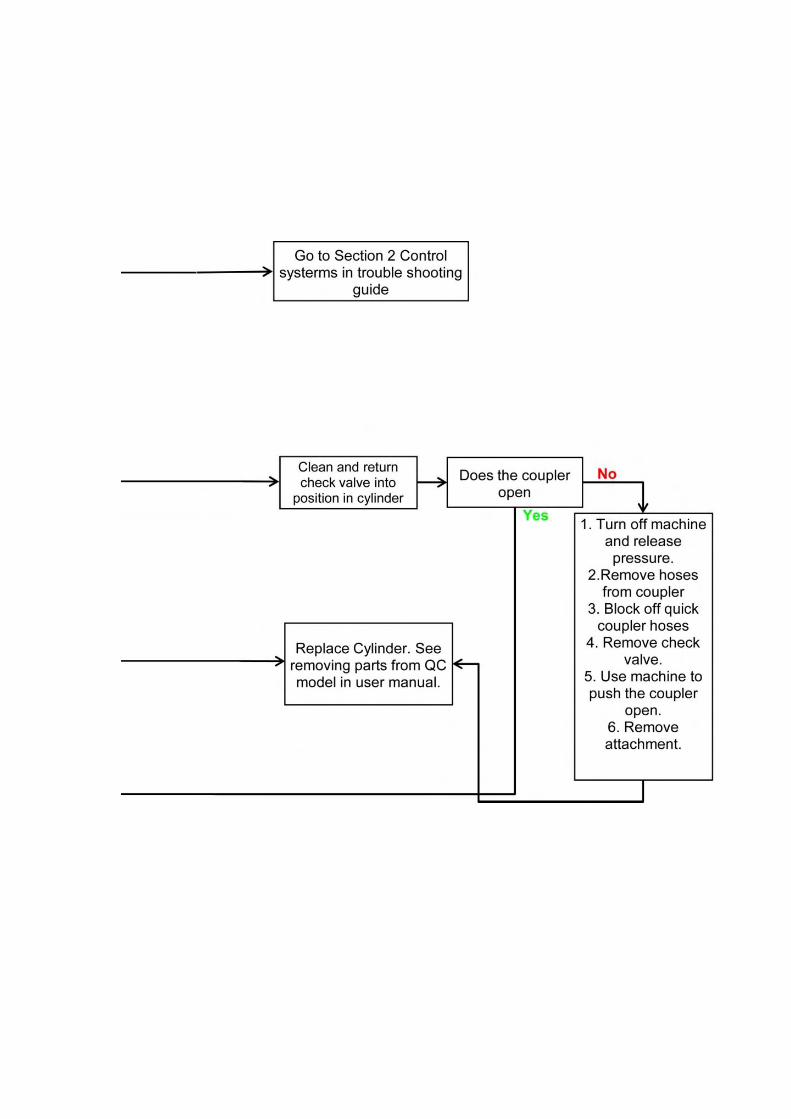
8. Trouble Shooting Guide
These flow charts are a representation of how the Geith system
works and can be used to assist in the Trouble Shooting process.
Please contact your local Geith representative for assistance if
problems persist.


9. Warranty Program
The Company warrants the Equipment (except for parts) sold by it to
the Purchaser to be
Free of defects in material and workmanship for a period of twelve
(12) months (maximum of 2000 hours of use) from the date of
shipment or 18 months from shipment to dealer.
The applicable warranty time period for parts shall be six (6) months
from the date of shipment and for reconditioned parts shall be three (3)
months from the date of shipment.
No warranty will be accepted for wear/damage on products or
components thereof.
The company will provide a new part or repaired part, at its election,
in place of any part which is found upon its inspection to be defective
in material or workmanship during the periods described above.
Such part will be repaired or replaced without charge to the purchaser
during normal working hours at the place of business of a distributor
of the company authorised to sell the type of equipment involved or
other establishment authorized by the company. Purchaser must
present proof of purchase (and purchase date) at the time of making a
claim under this warranty.
This warranty does not apply to failures occurring as a result of
abuse, misuse, negligent repairs, corrosion, erosion, normal wear and
tear, alterations or modifications made to the equipment without
express written consent of the company, or failure to follow the
recommended operating practices, or service and maintenance
procedures as provided in the equipment’s operating and maintenance
publications.

The warranty provided herein does not apply to engines and motors
which are manufactured by others as they are warranted by their
respective manufacturers directly to the purchaser.
Geith recommend that you install the Geith Quick Coupler control
system as supplied with every new Geith Quick Coupler. The Geith
Quick Coupler control system is a market leading tried and tested
solution.This system is designed to greatly simplify the installation
process, requiring no onboard computer configuration therefore
minimum user training is required. However if you choose to use an
alternative control system you must ensure that the control system
complies with Health and Safety requirements and is compatible with
your Geith Quick Coupler functionality. Failure to do so may result
in unintended operation of the coupler and will invalidate both your
warranty and any liability by Geith or any of its associated
companies.
A detailed description of terms and conditions of sale can be
found on QR39 Geith terms and conditions of sale which was
attached to your order acknowledgement. If you do not have a
copy you can contact your nearest Geith Distributor.


Finish and test procedure
Quick coupler to be worked through several cycles of opening and closing the hitch.
Machine to be left running for a number of minutes to show any leaks after start up.
Load test procedure as shown below to be completed before final sign off.
Any problems with fitting the kit or with the operations of the hitch to be reported back
to Geith International.
- Visually check the hydraulic cylinder for leakages at pipes and rod seal. Replace if necessary. - Internal piston seals can wear over time and are more difficult to check for performance
degradation. One method of checking these seals is to
o Ensure test is carried out in a secure, controlled area and is clear of people. o Connect an attachment to the coupler and open
or curl the coupler back to load the hydraulic cylinder with the weight of the attachment.
o Lower the attachment to within 300mm from ground level.
o Switch off the machine and leave machine at
rest for a nominal period of 10 minutes,
while observing any change to the position of the quick coupler engaging plate. If the position is seen to drift inwards (hydraulic cylinder is in-stroking) then it is an indication of potential loss of oil over the internal piston seals in the cylinder or a potential problem with the cylinder check valve failing to sufficiently retain the oil in the cylinder.
o Should drifting occur: Outstroke Quick Coupler cylinder to engage the attachment pins.
Lower attachment and coupler on to the ground and Switch off machine.
Remove the hose from quick coupler cylinder port ‘V2’ and plug the removed hose to prevent loss of oil.
Clean away oil residue from cylinder port. Start machine and repeat the above procedure.
Observe the cylinder port for further or continued oil flow/seep. If oil flow is evident then there is an indication that the piston seals need replacement. Replace the piston seals and repeat the test procedure once more. If there is continued drift then the cylinder check valve should be replaced and again a
re-test should be carried out to confirm resolution of the problem and the cylinder functions correctly.
- Review any previous maintenance history on the product - Look for evidence of previous repair or re-work - Document and hand to senior site supervisor, all noticeable issues resulting
from the inspection
WARNING!
WARNING!

FFit up arran
geement for solen
oid valve

EElectrical insttallation
procced
ure

C Circuit in
stallation map

Explod
ed bom
of hyd kit for p
repiped mach
ine
Control System Used
to activate the Hitch.

E Explod
ed BOMM of h
yd kit

Installation kit bill of materials
Compatible with "Coupler Circuit Diagram with Pressure Switch and 4 port valve" 823000053248A
Quick-Hitch Kit for Enter Machine make
and Model
ItemDescriptionPart NumberQuantityCheckUnit CostTotal Cost
1BOOM HOSE11ABOOM HOSE12LINK HOSE1
2ALINK HOSE13PUMP HOSE1
3ATANK HOSE14Relay Enclosure assembly c/w Pressure Switch154-port solenoid operated valve assembly70100005325416Geith Control Box57696171/4" x 1/4" Male-Male Adaptor1181/4" Bonded Seal1491/4" Barrel Adaptor7B/4-42101/4" Banjo BoltRX04MBMG2111/4"x1/4" restrictor112In Line Check ValveVU14M1132 Core Cable c/w DIN connector (assembled)6 mtrs14 PUMP ADPT
14ABonded Seal15Tank Tee 16Bucket Adaptor
16AAdaptor16BBonded Seal17Double 1/4" Hose Clamp
17ASINGLE 1/4" Hose Clamp18Instruction Sticker65006119Warning Sticker56311120Warning Sticker563121217mm Cable Ties5022M6 x 50 Hex Head bolt c/w nut and washer223Bucket Adaptor Optional TN/A24Optional Pump ADPT.Optional T125Pilot Operated Check Valveneed serial no.126Hydraulic Cylinder Seal Kitneed serial no.127Pressure Switchas per item 4128Hydraulic Cylinderneed serial no.129Valve mounting Bracket 701000053255130M12 x 60 Hex Head bolt c/w lock nut and washer131H.A. 3000mm x Europulse-04S c/w ST/90sBUCKET132DIN FEMALE CONNECTOR C/W SCREW AND SEAL1

36. The hose from the quick coupler cylinder outstroke port is connected to valve port `A’.
The hose from the quick coupler cylinder instroke port is connected to valve port `B’.
Connect the hose from the bucket supply line `T’ piece to the valve port `X’.
37. Secure hosed solenoid valve to the panel wall using bolts supplied.
At this point it is advantageous to attach an earth wire with ring terminal to one of the connecting bolts. The other end of the earth wire is to be connected to the solenoid valve plug.
38. Using the electrical cable supplied, make connections to the solenoid plug terminals and connect the plug to the solenoid valve.
39. Secure the plug to the solenoid valve as shown.

Option 2 – 5 Port Solenoid Valve
33. Insert `T’ piece at join of flexible hose to steel pipework at base of boom, once again checking that it is on dipper bucket ram outstroke port supply line that you are making the connection to.
Connect the hose end to the `T’ piece branch and run the hose through the panel opening to the pump compartment as was done with the previous hoses. This hose is then connected to valve port `X’.
34. Connect the hose to the pump test port. On twin pump systems this is typically pump No. 1. This should always be confirmed by ensuring that it is the same pump that operates the dipper bucket ram. It is always good practice to fit a `T’ piece to the pump port as this allows the test port facility to be retained.
35. Connect the hoses to the ports of the solenoid valve at this stage as follows.
The hose fitted to the tank connection `T’ piece is connected to the valve port marked `T’.
The hose from the pump is connected to valve port `P’.

Using the electrical cable supplied, make connections to the relay box assembly and then using the cable from the relay box connect the plug to the solenoid valve.
Secure the plug to the solenoid valve as shown.

It is recommended that you connect the hoses to the ports of the solenoid valve at this stage as follows.
The hose fitted to the tank connection `T’ piece is connected to the valve port marked `T’.
The hose from the pump is connected to valve port `P’.
The hose from the quick coupler cylinder outstroke port is connected to valve port `A’.
The hose from the quick coupler cylinder instroke port is connected to valve port `B’.
Connect the hose from the bucket supply line `T’ piece to the pressure switch.
Cable tie the relay box assembly and pressure switch to the hoses coming from the solenoid valve.
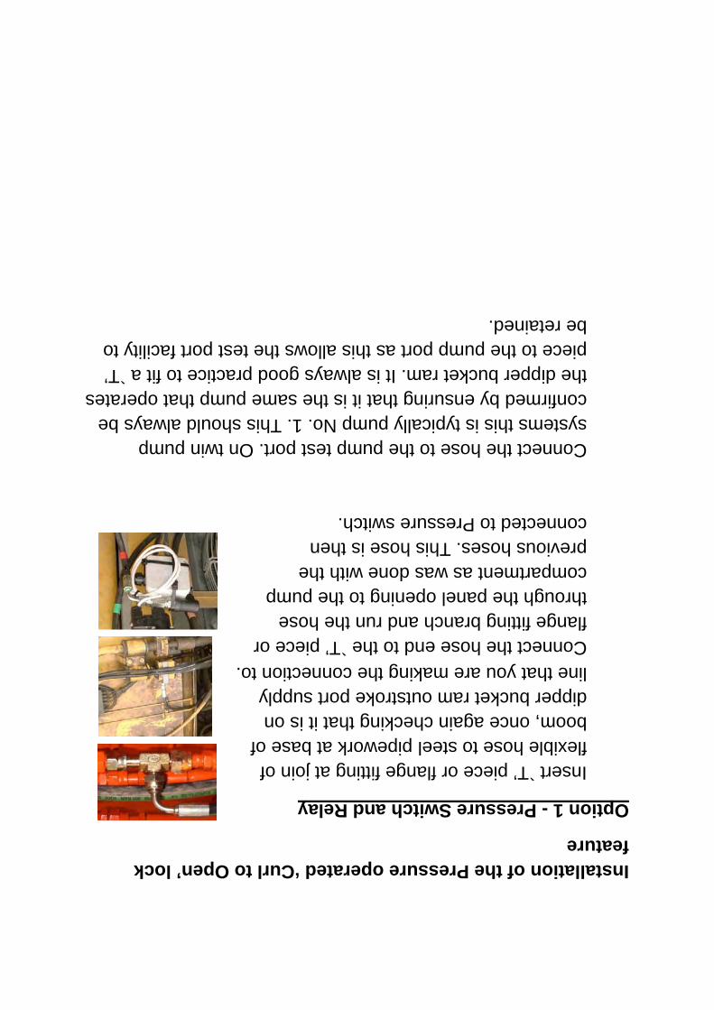
Installation of the Pressure operated ‘Curl to Open’ lock feature
Option 1 - Pressure Switch and Relay
Insert `T’ piece or flange fitting at join of flexible hose to steel pipework at base of boom, once again checking that it is on dipper bucket ram outstroke port supply line that you are making the connection to.
Connect the hose end to the `T’ piece or flange fitting branch and run the hose through the panel opening to the pump compartment as was done with the previous hoses. This hose is then connected to Pressure switch.
Connect the hose to the pump test port. On twin pump systems this is typically pump No. 1. This should always be confirmed by ensuring that it is the same pump that operates the dipper bucket ram. It is always good practice to fit a `T’ piece to the pump port as this allows the test port facility to be retained.

31. Obtain the Bucket ram `T’ piece fitting from kit. This fitting is dependent on machine make and model and may not look exactly like the samples shown opposite.
32. Identify the dipper arm bucket ram outstroke port supply line and follow this line back to the base of the boom. Take care to account for any crossover lines that the piping may take along the route.

27. Locate suitable position for fixing of solenoid valve in the pump housing compartment, typically on a compartment wall as shown or use mounting bracket supplied. Mark location of valve retaining holes for drilling.
28. Drill fixing holes in marked position as shown, taking care not to drill into any part or component that maybe located on opposite side of the compartment wall being drilled. Do not fit valve to panel at this stage.
29. You must now fit remaining hoses to the tank, pump and bucket ram supply hose as follows.
Make sure that the tank pressure has been released by pushing vent button on tank.
30. Connect tank `T’ piece fitting to tank port and connect hose to branch as shown. Feed hose end through compartment panel to pump compartment.

23. Continue this process until the hose is fully attached along existing pipework up to the end of the boom.
24. Snip off end of cable ties to leave a neat finish to hose installation.
25. Continue to run the supply hoses along the existing pipework and secure in place with supplied cable ties. Snip off cable tie ends to leave neat finish.
26. Continue to run the quick coupler supply hoses from base of boom in through compartment wall inlet to main pump compartment ready for connection to pump and supplied coupler solenoid valve.

19. If using manifold block option, attach supply hoses to remaining two centre ports in block and run hoses up dipper to top hose clamp block. Secure hoses in clamp as before.
20. At this point you should check the manifold hose arrangement throughout the working cycle, to ensure adequate hose clearance and movement especially in the curled out position as shown. It is important that the hoses do not get trapped in the arm linkages as this will cause wear and hose burst problems.
21. With hoses secured to dipper arm you must now run the hoses along the existing dipper ram supply hose line and cable tie in place along the full length of the boom.
22. Secure to existing hose at approximately 300mm centres between cable ties.

Option B.
15. If the hose manifold block option is supplied the two single hose block clamps will not be required, as the manifold block is used to route the hoses by an alternative method.
16. If the optional hose manifold block is supplied in the kit, then prior to welding the block base to the dipper arm you must first connect the quick hitch jumper hose to the block outside ports as shown.
17. Then with quick coupler fully curled inwards as shown, position manifold block on dipper arm with hose connections pointing up the dipper arm towards the excavator cab.
18. Position the manifold block so that the jumper hoses to the quick coupler have freedom of movement through full quick coupler rotation cycle. Follow the procedure from previous steps to securely locate the block base plate to the dipper arm in the selected location.

12. Run the unsecured portion of the jumper hoses up to the next hose clamp block previously fixed to the dipper and secure hoses in place as shown. Fit male/male hydraulic adapters supplied to hose ends ready to join remaining supply hoses in place.
13. Join supply hoses in place and tighten to secure.
14. Pull hoses along dipper and secure to top hose clamp block as shown.
Go to section 21.
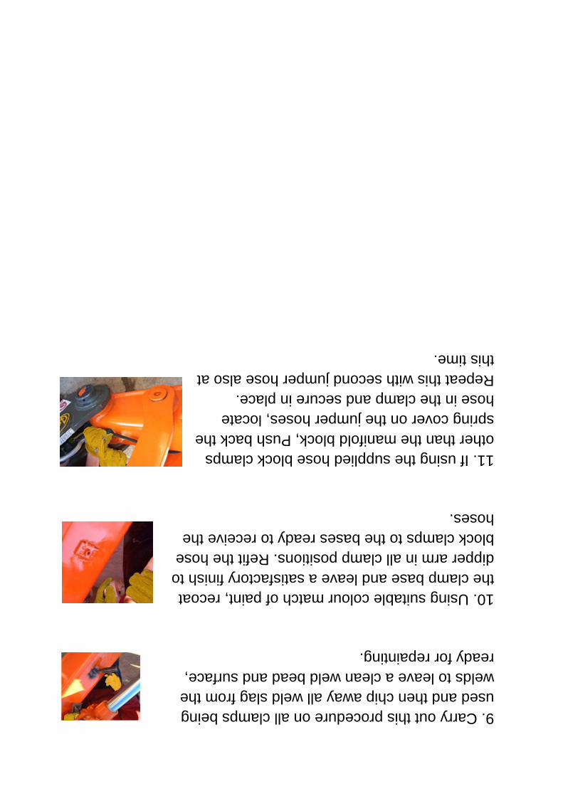
9. Carry out this procedure on all clamps being used and then chip away all weld slag from the welds to leave a clean weld bead and surface, ready for repainting.
10. Using suitable colour match of paint, recoat the clamp base and leave a satisfactory finish to dipper arm in all clamp positions. Refit the hose block clamps to the bases ready to receive the hoses.
11. If using the supplied hose block clamps other than the manifold block, Push back the spring cover on the jumper hoses, locate hose in the clamp and secure in place. Repeat this with second jumper hose also at this time.

Option A.
5. Note there are two double hose block clamps and two single hose block clamps supplied for fitting to the dipper arm. The two single clamps are for fitting to the end of the dipper at the quick hitch and are separated so as to route the hoses to each side of the quick hitch cylinder.
6. Using the corresponding hose block clamps supplied in the kit, mark the shape of the base of the clamp at each of the previously marked positions on the dipper. Ensure top clamp is located to one side and angled slightly to direct hoses along the side of the boom.
7. Using a sharp edged tool, scrape off paint cover at edge of marked areas to allow good contact to metal for welding of the hose clamp bases.
8. WARNING it is critical that machine is properly grounded to the welding plant before welding begins. Serious damage may be done to the excavator if not correctly grounded. Position the hose clamps in their pre-marked position and weld along top and bottom edges of the clamp base plates to secure in position.

QH & Boom hose installation procedure
(NOTE: this is a generic fit up of a machine and is a representation as to how to fit up all machines. Some variations in fit up may need to take place.)
1. Open kit box and remove all components. Lay all components out on a clean workbench or work area, taking care to avoid dirt that may contaminate the hydraulic system when connecting the hoses and fittings.
2. Obtain the quick coupler hoses (part 2 and 2A) in exploded BOM of hose kit and attach to the quick coupler hydraulic cylinder (one on either side of the port block) as shown in fig. 1. Tighten to secure in place.
3. Fit the quick coupler to the excavator before any further installation commences. Ensure that any `O’ ring seals required are fitted to the quick hitch as shown in fig. 2 on both link and dipper positions.
4. Using a suitable straight edge square and a marking tool, mark the position for the supply hose clamp blocks on the dipper arm of the excavator as shown in fig. 3. These positions approximate to the bottom, middle and top of the dipper.
Fig. 1
Fig. 2
Fig. 3

Place safety / maintenance decals close to the control box where they can be read easily.
Locate a suitable 12/24V fused appliance, such as a cigarette lighter circuit. Establish the positive supply wire, using a DC tester.
Connect the electrical box into the chosen existing circuit as shown in the Electrical installation procedure drawing (section 6 in manual).
Connect the two-core wire supplied as shown, and run it down though the engine compartment to where the solenoid valve will be fitted.
With the control box fully connected, ensure that all wiring is fully secured and that there are no trailing or loose wires is left that the driver that may be snagged and damage the connections.
Using the tie wraps supplied, secure the two-core wire or conduit as the case may be, the entire way along to the existing wiring in the engine compartment.

Installation
Before starting the installation of the Quick Coupler Hydraulic kit, please ensure that you have read this installation guide/instruction fully and understand the fit up process.
Schematics of electrical and hydraulic systems are included to give better understanding of how the system is intended to function and how to fit it correctly.
Fitting of in-cab decals and control box Note: Please follow the preparation and fitting instructions as per adhesive manufacturer guidelines as outlined below. Failure to do so will result in poor adhesion and will result in decals and control system becoming detached from cab window.
Preparation and fitting instruction:
Select area that control box is easily accessible but not in risk of being impacted or bumped and knocked off the window.
Window must be cleaned with an isopropyl alcohol wipe, supplied in kit.
Heat the machine cab up until it reaches 20ºC / 68ºF to dry excess moisture and heat the window.
Remove adhesive cover on back of control box and press firmly onto the window.

Installation Guide Contents
1 Installation
1.1 Fitting of incab decals and control box
1.2 QH & Boom hose installation procedure
2 Installation Kit Bill of Materials (BOM).
3 Exploded BOM of hydraulic kit
4 Exploded BOM of hydraulic kit for prepiped machine
5 Circuit installation map
6 Electrical installation fitup
7 Fit up arrangement for solenoid valve
8 Finish and test procedure

Top Related