


Languages
Pages
Legal


r THE GENERAL RADIO
Experimenter
This Issue:
All Bol1d..at.a.t.e, Low-·Distortion Osc1llator
B1ne-Squared. P'I,lese
VOLUME 40. NUMBER 3 I MARCH 1966
IET LABS, Inc in the GenRad tradition
534 Main Street, Westbury, NY 11590 www.ietlabs.com
TEL: (516) 334-5959 • (800) 899-8438 • FAX: (516) 334-5988
2
the [;!Expe t'i ITl e nte t'
10 Hz TO 100 kHz
ALL-SOLID-ST ATE, LOW-DISTORTION OSCILLATOR
SINE- OR SQUARE-WAVE
The Type 1309-A is the secood in our new line of general-purpose variable-capacitance-tuned RC 05-
ciliatars, recently introduced with the Type 1310-A Osciliator.1 It con· tinues the modern, all-solid-slale design used in the Type 1308·A ond Type 1311-A Audio Oscillators.
The ('ontinuing need for greater atcurucy in rlectrical measurements, til(' improvements in sound-1'('cording and reproduction equipmcnt, and th(' increullingiy stringent requirements all
communit'ation sYbtems have alt lowered the [evel.., of distortion acceptable in new equipment. To design and to test this equipment, uceurat<' distortion measurements must be made, und an 'ROMrl 1::. O ... ~n. "' \ \I".JMn. W,d .. fla.nte Re 0..,11.· lOr."' G.~"nl Rnd,~ E~/H"_~I ... \".",,1191\5.
csscntiu l part of any harmonic distortion measurement. i ~ :~ low-distortion souree.
.\ s distorLion spcrifi<"tltions h:we tightened, generators with lowN and lower d istortion levels h:1\"e become available. but most of them hav(' been quite expcnl$i\'e owing to:1 concomitant emphash~ on extreme amplitude stability and a flat. frequency eharn<"icristir. In lower-cost, gencral-purpose oscillators, on the other hand, the tran.<;.itioll from \'tJ.ctlum tubes to transi"tors has led to higher, rather thall lower, di.stortion levcls. as a result of thc techniques u"ed 10 obtain these additional ('harncteristics.
The new Typ~; I:!OO-A Oscillator, Ull
all-solid-st.ntc, c!1pacita llcc~tuncd oscillator, combines very low distortion with accuracy and stabilit.y ample for
@ 1M6_GENIIAL IAOIO COM~ANY, WUT CONCOlD, "'AU~ u.s.A.
IET LABS, Inc in the GenRad tradition
534 Main Street, Westbury, NY 11590 www.ietlabs.com
TEL: (516) 334-5959 • (800) 899-8438 • FAX: (516) 334-5988
O'HERO,IIAl \I/ ,EH BRIDGE AW'llFiER ~~
T
,-
gencral laboratory lISC. Output is quite constunt. over the entire frequency range of 10 Hz to 100 kHz, und an output uttcnuutor provides the low signal le"els ncccss.'lry for testing active devices. As with other General Radio Re Oscillators, there is an input.-out.put. synchronization jack. An added feature. is ll. square-wave output for transientresponse me:lsurements. This output. has a 'symmetrical waveform and an unusually short rise ti me.
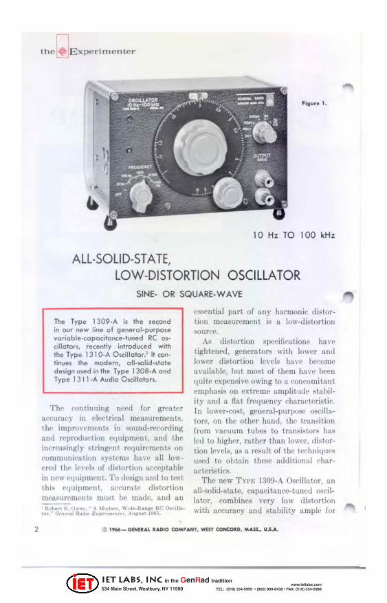
l;'igure 1 is a panel vie.w of the oscillator, and Figure 2 shows the t.hree m~dor elements: a low-distortion Wien bridge oscillator, a Schmitt. squaring circuit, and an output attenuutor.
DISTORTION
The low distortion is achieved through the usc of II high degree of negative feedback and a thermistor of , Hobo.t K O"'tn. "SoIi,I·StMe EtC O.ciliAto. DNiK" lot Audio Ule" . .Io .. r~nl ojlh Audio J..'nlli"u,inQ &':i.I~. Vol 11. January. 1!lOO.
,
,"-"-
, l'
, •
1"-f'.,
,
Sf'[C,F,CAlION
l',>CAl ~oo •• ,,, 2
f ll(OU( ~ C'
Ma,.c:h 1966
Figure 2. Blo~k diagram of Type 1309·" Oscillolor.
SC"MITT .2......C'Rcu,t
__ "T" _____ -,
, 60-G8
STEP ATTENUATOR
20 .... 8 ~_RIABlE ~lIENUATOR
OUtPUl .,'"
special design for amplitude cont.ro!.: The distortion at full output ii; approximately cOllstnn l, with load impedance for all)' linear load of noo ohms or greah'T. WhclI thl' opclI-circuit output is olle volt or less, the distortion is indepcndent of the sizc of thc load . The d istortion is t,ypica lly less than 0.01% for frequencies ncar I kHz , often below wha t ('un be ~'onvenielltJy mcasured. ~ote that the shape of the d istortion cun'e (Figurc :J) is typical of most audio-frequen cy dcvices, so that the margin between the source cltstor· t ion and a de\' ice undel' test remains approxi mately constant with frequency.
Low levels of hum nnd noise arc always desirable, but to be uscful for broadband distortion measurements all oscillator must ha ve noise and hum that nre at least as low as the distortion. The I-k Hz output of the Tn'[; nW!J-A has noise typically less than 0.005% ill a bandwid th of !i H z to .-)00 kHz, and
/
1/
, " ro
/
V fll1ur . 3. O •• il . loto, dls tort lo .. for 600.ohm load or op . .. ,i,cull.
3
IET LABS, Inc in the GenRad tradition
534 Main Street, Westbury, NY 11590 www.ietlabs.com
TEL: (516) 334-5959 • (800) 899-8438 • FAX: (516) 334-5988

the[;jExpel'imenter
l:~t I III III III I < '0'" zo ~o tOO ZOO ~oo t_H. 2 ~ 10 20 $0 100
FIIEQUENCY I!!!'!:m
flgur. 4. TypIcal a.clllata. outpul ... ollog ....... u. fr.q .... ncy .
hum is l('SlI t.han 0.001 % (-100 dB) of the full output.
ATIENUATOR
The sinusoidal opcn-tireuit output voltage can be varied continuously between;' volts and less than 011 millivolt by means of the output attcnuator. An additionnl pos.ition, labeled zero volts. discoJlllect.~ the oseillator output from tbe terminals yet maiJltains the 600-0bm output impedallce. Tbis provides 0. convenient transient-free means of reducing the output to zero without disturbing the continuous attenuator sctting or shorting or disconnecting a carefully shielded system. Furthcr, it aids in loea ling ground loops Ilnd other sources of extraneous signals when one is working with small signal levels. With the oscillator output removed , the extraneous signals are not maskcd, so that they nrc easier to measure and to eliminate. This technique offers considerable advantage over the of tenused one of short-circuiting the output. Shorting drastically ehanges the im-
pcdance levels and can, in cffect, change the whole circuit, po.r;sibly climinating the very sQurce that one is trying to isolaLe.
The variation of the output of any oscililltor at different frequenc ies is perhaps its most noticeable departure from ideaL Beeause of this, and because a constant output is convenient for response measurements, most modern transistor oscillators have relatively flat output-frequency characteristics, although this property may be accompanied by moderately high distortion, which is uniform across the frequency range. The output of the Twt: 130!J-A is constant with in ±2% over its whole frequency range a nd is typically within ±O.5% (see Figure -I ). It is stable within ±0.2% for one hour, typically, under normalluboratory conditions and after warm-up.
One position on the step attenuator cOllnects the high-speed Schmitt circuit to the sinusoidal oscillator. Symmetriclll, positive-going square waves with u rise time of less than 100 nanoseconds
FIg .... 5, n.fl) l . odlng .dg. 0' 10_k Hz .q .. a .. w o .... Inla 50 _010", load. Hariunlal teal" SO n./di .... (Rlglol) DI .. cl.coupled 10-Ht Iq ... o .. w a .... hu IlallOp. Harlzonlallcal" 10 "' "/d l ....
IET LABS, Inc in the GenRad tradition
534 Main Street, Westbury, NY 11590 www.ietlabs.com
TEL: (516) 334-5959 • (800) 899-8438 • FAX: (516) 334-5988
into 50 ohms nre thell available at the output terminals. This rise time is typically 40 nallos<'Conds into .:')() ohms a.t full output, which eorl"("!;ponds to the response time of an amplHier with greater than 100MHz bandwidth. (See Figure .).J This output is grt'ater than :j volts, peak-to-pcuk, open-circuit, and is d('-{'ouplcd through the 2O-dB sttcnuntor, so that the waveform is flattopped even at the lower frequency limi~ of 10 lIz.
SYNCHRONIZATION
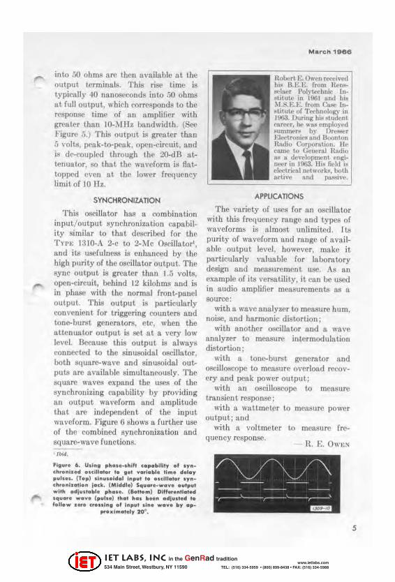
This oscillator hUB u combination ~nJlut!o~tput synehronizatioll capabilIty simIlar to that described for the TYI'~~ J:110-A 2-c to 2-l\ lc Oscillatorl a~d its usefulness is enhanced by th~ high purity of the oscillator output. The sync output is greater than 1.5 volts, open-circuit, behind 12 kilohms and is in phase with the normal front-panel output. This output is particularly convenient for t riggering counters a nd tone-burst generators, etc, when the attcnuutcr output is set at a very low le\"el. BeCAuSC this output is always connected to the sinusoidal oscillator both square-wave and sinusoidal ou~ puts are available simultaneously. The square waves expand the uses of the synchronizing capability by providing lln output waveform and umplitude that are independent of the input waveform. Figure 6 shows a further use of the combined synchronizatioll nnd square-wave functions.
'I"'''. FI" .... 6. U.ln, phclI ••• hlfl c.p.blllt~ ., I~ '" ch .... i,.d •• clll .. , •• 1. ,., " •• I .. bl . 11m. d . l .. y p .. I •••• (T.p) Il n ..... ld .. 1 In p .. ' , ...... III.' •• '~n -ch ... nl ... " ... I .. . k. (Mlddl.) Sq ....... w." • • ""p .. ' wllh .. d ]usl .. bl. ph..... "."om) Dlff ..... I1 .. ' . d .q .......... (p .. I •• ) lh .. , h .. . b ..... di ... I . d t. ,.n.w ..... cr ... r .. " .f I .. p .. ' lin. w . ... by .p_
pr.",I",.I.ly 20".
Robert E. Owen rCf't.'iVNI 1.i~ I3.E.E. from nl'n~ -",-,I!ler "olyt.cchl1k Lo@titutc in 1001 snd hiM M.S.KK from c.u.c 111-"l.itulto of T('d1110IolQ' ill 1003. During hiJo ~tud('nt car~r, he 11>118 cmployl'd lIum'T\('n by DrC!lIICr Ell'('troniCB and Boonton Radio Corrklrfltion. Ill' came to Gcncnd Hallio 8~ So dcv('lopm<·nt Nl$tinl. ... ·r in 10Ga. IInl field is cll~triCfllll1'twnrb, both Jl.rtlvc /lnd pulISivl'.
APPLICATIONS
The va.riety of uses for Ull oscillo.tor with this frequency range fl.nd types of waveforms iIi almost unlimited. I U!
purity of waveform and runge of available output level, however, make i t particularly valuable for laboratory design and measurement usc. As an example of its versatility, it can be used in audio amplifier measurements as a source:
with a wave analyzer to measure hum noise, and harmonic distortion' '
witb another oseilla tor and' a wa ve analyzer to measure intermodulutiol1 distortion;
with 11 tOlle-burst generator and oscilloscope to measure overload recovery and peak power output;
with a n oscilloscope to measure transient respon.sc;
with a wattmeter to measure power output; and
with II voltmeter to mensurc frc-(Iueney responsc.
lL E. OWEN
5
IET LABS, Inc in the GenRad tradition
534 Main Street, Westbury, NY 11590 www.ietlabs.com
TEL: (516) 334-5959 • (800) 899-8438 • FAX: (516) 334-5988

6
Figur01. Th,Typ,I30'9. A. QulllolOr olld ouodo,. d '<fUlpm.II' uud fo, '0.1· I .. g of 0 .. oudlo ompllfl ...
SPECIFICATIONS
fREQUENCY
b .... , 1011"1 W 100 kill in four decade rang .... C ... ,,,I, Continuoualy adjustahle main dial Mvel'll range in I turn, nrnier in -II ~ tunle. A.uu,,~y , ±2("; 5), .. 01"01110011011 ' An l')(u'flUII refcrence lignal (,fin he introducOO lhruul/;h I)hone jack to "hlllCl(I('k oerillator. One-volt input providMJ ± 3% 1000king rangt'o Ff"I'(luem:y diAl ran be ull'd for I)hslll" adjuetment.
OUH'UT
Si .. w . ... ro ...... , 10 mW inlo (j()()-lIloOO
Vollog .. 5,0 r ±5% open rireuit.
lrnpedoll<" tiOO II. One Wflninal grounded.
COlli .... \linimum of 2O-dB ('Untinuoual~ adjuatahl" and 00-d13 IWp alwnuaWr (20 ± 0.2 dB I){'r Itep). AlIO, II I<'l'o-volla output poaitioll with liOO-ll output impedanC't' maintainOO.
Olflorlioll ' 1..e811 than 0.0:'1% fn)fll 200 li z to 10 kllz, increasing til leu than 0.25% ilL 10 l iz and 100 kl h open riT('uit or 600 o. ~ Figun' 3.
F"<fu.II<)' Chorododltl.. *2% over .... hol" freqm"nrf range for loada of 000 II ('I' grealer, ~ I\'pi('& \'Un'''' in Figure 4
H .... " LetIII than 50 IO\' n·pnll('M of atWnuator telling (0,001% of full outl)llt)
Sy .. ~hro"'totlo .. , IIith-impt'dance (12 kfl), MilItant amphlud .. "utput of AlllltOximatel), 1.5 voila fur Ute \lith external rounWr, for tl'l!(gcring an 08CiII()8('()pe, or for Iynchronizing other necillaWts. Squ ... Wo". Vol.o"" Greater thrul +:'1 v, pCllk-l()openk, opt'n-('i rcuit. DC-OOUllloo output. Im,....oll .. ' 000 Il. Itln TI .... , Under 100 nil into 50 11. 1'yI)j('slIy 10 n. at full output.. C ... "olt :\I inimum of 20 dB ('Ontinuoully lidjuetable attenuator only. SymmOlry ' * 2'( over whole frequcncf rnnge.
O£NERM formillol. : T .... ,{) TYIH' !J:~ !linding I'OlltA, unl! grounded, AU"'''i'' S ... ppll.d , Type CAI'-22 I'o\l"r o,rd, llpare flllll'll. Au . .. ori .. A." o!lobl" Type J:'!OO. I'!l5 Adapt{)r ('abl~ (telephone plug to Type 274-:\1 Double Plug) for l't)llneetiOI1 to synchronizing jllck, relay- rack Ildslltor III't. , ....... hq ... lo.d . 100 to 12f) V, 200 to 250 V, :;0 to 400 li z, G W. M ....... i .. g: Con\"('rlibl~bench cabinet Olml .. slolll: Width 8'., height 6, de/lth 81~ inchet (210 by 1M by 2\0 mOl), o\'e r-a I. N.I W.lghl , 6' .. Ib (3. 1 kg).
/)ttcripliun l"rict
i", USA
1309.9101 1560.9695 0410.9638
typo 1309. A Ouillolor, 10 HI - I OO .. HI typo 1560. '95 Adop'" Cobl. Typ' 410_"01 Itock-Adopl.r S ..
$]25.00 3." 7."
IET LABS, Inc in the GenRad tradition
534 Main Street, Westbury, NY 11590 www.ietlabs.com
TEL: (516) 334-5959 • (800) 899-8438 • FAX: (516) 334-5988

MareI'! '966
GENERATION OF SINE-SQUARED PULSES WITH THE TONE-BURST GENERATOR
Sine-squared, or raised-cosine, pulses are useful ill testing broodbund transmission systems und , in particuhtr, ill video-bandwidth tests of television systems. J Tbe sine-S<IUi\fed pulse, for instance, resembles vcry closely the elet'trirul pulse from n telev ision camera corresponding to a I'Itunned white line. The spectrum envelope of a sinesquared pulse is shown in Figurc 1 with that of u reewngular pulse for compariSOil . Abo\'c twicc thc fu ndamentaL the sine- squared pulse has no components of appreciable magnitude. Below that frequency, howcvcr, its spectrum resembles very closply that of the rertangular pulse,'
Sine-squared pulses can easily be prodlH'ed by the TYPE 1::59G-A Tone-Burst Generator. By means of the gating COIl
trois. thc interval bet ween pulses ean be set at I, a. 7, I.j, :31 , Ga, or 127 periods, or from I millisecond to 10 seconds with 11 limed control.
To generate sin~squared pulses lI'ith the Tone- Burst Generator. proceed as follows :
1. Connect a 10 I ' -- ' 1HZ cflpnl'itor be-
tween upper term..inals of the S IGX.\!,
(lef,1 Fill y. e 2. 0 .. . · .~cI . , j .. . . w"v. bunl. (C.llle') Figure 3 , One· .~ .. . bun' lIC1ted ClI p . Clk , (Rlllhtl Fillu" 4.
Sin"'qu" .. d pub.,
:1L-1L o,~ ",
i.,f---'\"'---~----4 ,
., " ' .. "", ... ' • ~.
FIII U" I . Sp.ct.um e .. ve lop .. Clf CI ' e<'"nlluICl' pu t .. Cllld CI .1 .. . . s quCl' . d pu l ...
IXPl' T nnd TIlIIXG 1:\,I'l"T pairs. 2. Apply n s ignal of the desi red fre
quency , j , to the ::; IGl\"" .... L IXI'("T terminals.
3. Set both G .... TE OntA'T'IOX switches to 2.
.\. Set C \ ·CI.E COL'"X ','S switch to MI
X l ':; O"'E. This produces olll"cy('!c bursts ~imilar to those of FilWl'C 2 as seell 011
nn oscilloscope. S. By means of tbe Jo' I.0l'E switch and
l'fllGG t:I( LE\'EI. contml. chnngc the phuj.;(' of the pulse .so that gating occur::; at pellk points, as in Figur(>:J .
1 Nel.on . Jo,ellb K " T ele,·j.ion . nd Sjne.8Quer~ Te"" n.:. " T.I:/,oniL M",rr S~O~ . .... pri I IOO-i. 'Col, n 'h~rT)'. P wlH. ~ nd T'Bft.i •• b i. Co .... ~n>«l/iu Cin: ~iJ •• Chl'", . n nnd II_ U. LId .. London . 1 \1~ 9. PI! 171;-] 81.
7
IET LABS, Inc in the GenRad tradition
534 Main Street, Westbury, NY 11590 www.ietlabs.com
TEL: (516) 334-5959 • (800) 899-8438 • FAX: (516) 334-5988
the~Exper i ITI e nte r
{i. Add Ii dc voltage source in series with the input signal and udjust this voltage to remove the steep part.'i of the waveform and to produce the sinesquared pulse of Figu re 4.
7 . Set GATE DUHATIO~-CI,OSj,;D switch to desired (,yeles interval betwccn pulses. Alternatively. if a continuously adjustable interval is wanted , set to X 1 or X 100, and adjust Tlm:o control to give desired interval.
The value of the capacitor between the signal and timing inputs is not critical. Its purpose is to shift the phase of the timing signal relative to tbe input so that when switching occurs at the peak points the input circuits arc
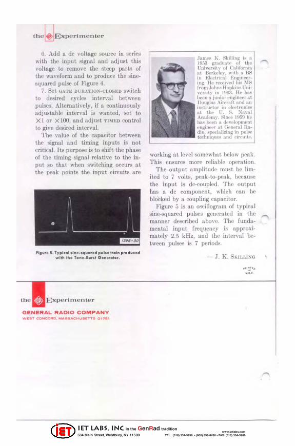
Flg u •• S. Ty p lc .. l.ln. _lq ....... d pul .. 1 ... ln p ... d ... c. d w il" ,,, . Ton._B ..... , G. nerolo •.
G ENERAL RADIO COMPANY Wl!tlT CO" COfilD. M"'SIl"C~Utlr.TTtI 01711'
.Jllmt·~ J\. i"-killing i~ II 10r13 gradual" uf till" lJllin'r~it\" of ('nliforniR at Ilerk"'tt·\,, "ilh H H." ill EI('Clrif':11 I-:nl[;n('('rin". 11(' r('('('i\'(·..:1 hi~ M:-; from John~ lIupkin~ l 'ui\'l,t~it" in HKi3. lie h:l.'l hl'l'n :i. junior ('Iljl:ineet at Douglas Air('mft :Inti lin
in,..lrut'lor in f'1('('lrnnjpl< :IL tht' l '. :-:. ;\"111'[11 Aradl'my. :-;inr" 1!J5!) Ill" hill' beNI R tll'l'elopnwnl enginf'f'r nt \'('twf!ll H:Idio, sJl"f'ialiting in Il111!lf' techlllqll('~ !lnd rif('uil~.
working at level somewbat below peak. This ensures more reliable operation.
Thc output amplitudc must be limited to 7 volts, peak-to-peak. because thc input is dc-cou pled . The output has a de component. which can be blocked by a coupling capacitor.
Figure :1 is an oscillogram of typical sine-squared pulses generated in the manner described above. Thc fundamental input frequency is approxi· mately 2.5 kHz, and the intcrval between pulses is 7 periods.
.1 . K . SKILLI~G
"':;"' . ...
IET LABS, Inc in the GenRad tradition
534 Main Street, Westbury, NY 11590 www.ietlabs.com
TEL: (516) 334-5959 • (800) 899-8438 • FAX: (516) 334-5988
Top Related