n GENERAL RADIO - Iet Labs GENERAL RADIO EXPERIMENTER ~~ ... mutual inductance lies in the in...
8
n GENERAL RADIO - EXPERIMENTER ElECTRICA L TECHNIQUE MEASUREMENTS AND ITS INDUSTRIAL APPLICATIONS VOL. XI N o.8 JANUARY , 1 93 7 THE MEASUREMENT OF MUTUAL INDUCTANC E . MUTUA L I NDUCT AN CE is olle of the most important properties of electrical circuits. By means of it the world's power is tran s mut ed from gen- erator \ 'o ltage to transmission line voltage and back to the ,'oilage s uit · a bl e for our motors and electric lights. Yet the measureme nt of mutllal in. ductance is of little impottance as co m· pared to measurements of self-induc- tance, capaci tan ce, and resistance. The major reason for this sligbting of mutual inductance li es in the in terest· ing fa ct that iron.core transformers arc nearly perfect. The mutual inductance helween the primary and second ary windings has 80 nearly its maximum va lue that no ordinary measureme nt of it could distinguish the minut e ,li f- ference. Such differences are of course of great impo rt ance and are measured by some characte ri stic of the trans- former itself, the voltage regula tion of a power transformer or its leakage re- ac tan ce, and tbe frequency character- istic of an audio transformer. The ge neral theory of coupled cir- cuits ilwolves at one ex trem e the closely coupled iron-core transformers just mentioned and at the other ex- treme the loosely coupled tuued cir- eujts of radio-fre'lucncy amplifiers, of wh ich the neutrodyne recei\ ' er of Ha z- e lt ine is an historical exa mp l e. Such loosely coupled circuits are now being used as band-pass filters al th e inler- mediate frequency of heterodyne re- ceivers. Mutual inductance is uni(lue in that il can exist onl y in the presence of self- inductance. An important measure of mutual induc tan ce is its ralio to the geometric lIlean of the two sel f· indnc- tan ces it ('"o nnects, ca ll ed the coe ffi cient of coupling, k. M k - ( J) -V Ll L2 which tUa y have any value fr om ze ro to ullit y. In loosely-coupled lUlled ci rcu it s the resonance curve has a s in gle peak for all values of coupling coe ffi cie nt ALSO IN THIS ISS UE : N ew W ave Filters A Handy Voltage D ivide r page 4 page 6 page 7 A Wide-Range R-F Choke IET LABS, Inc in the GenRad tradition 534 Main Street, Westbury, NY 11590 www.ietlabs.com TEL: (516) 334-5959 • (800) 899-8438 • FAX: (516) 334-5988
-
Upload
truongthuy -
Category
Documents
-
view
217 -
download
1
Transcript of n GENERAL RADIO - Iet Labs GENERAL RADIO EXPERIMENTER ~~ ... mutual inductance lies in the in...

n GENERAL RADIO -EXPERIMENTER
~~ ElECTRICAL TECHNIQUE
MEASUREMENTS AND ITS INDUSTRIAL APPLICATIONS
VOL. XI No.8 JANUARY, 1937
THE MEASUREMENT OF MUTUAL INDUCTANC E . MUTUA L I NDUCT AN CE is olle of the most important properties of electrical circuits. By means of i t the world's power is transmuted from generator \'oltage to transmission line voltage and back to the ,'oilage suit· able for our motors and electric lights. Yet the measurement of mu tllal in . ductance is of little impottance as com· pared to measuremen ts of self-inductance, capaci tance, and resistance.
The major reason for this sligbting of mutual inductance lies in the in terest · ing fact that iron .core transformers arc nearly perfect. The mutual ind uctance helween the primary and second ary windings has 80 nearly its maximum va lue that no ordinary measurement of it could distinguish the minute ,li fference. Such differences are of course of great importance and are measured by some characterist ic of the transformer itself, the voltage regula tion of a power transformer or its leakage reactance, and tbe frequency cha racteristic of an audio transformer.
T he general theory of coupled circuits ilwol ves at one ex treme the closely coupled iron-core transformers just mentioned and a t the other extreme the loosely coupled tuued cireujts of radio-fre'lucncy amplifiers, of wh ich the neutrod yne recei\'er of Hazelt ine is an historical example. Such loosely coupled circuits are now being used as band-pass filt ers al the inlermediate frequency of heterodyne receivers.
Mutual inductance is uni(lue in that il can exist only in the presence of selfinductance. An important measure of mutual inductance is its ralio to the geometri c lIlea n of the two sel f· ind nctances it ('"onnects, called the coeffi cient of coupling, k.
M k - ~- (J) - V Ll L2
which tUay ha ve any value from zero to
ullity. In loosely-coupled lUlled ci rcuit s the resonance curve has a sin gle peak for all values of coupling coeffi cient
ALSO IN THIS ISS UE : New Wave Filters A Handy Voltage Divide r
page 4 page 6 page 7 A Wide-Range R-F Choke
IET LABS, Inc in the GenRad tradition
534 Main Street, Westbury, NY 11590 www.ietlabs.com
TEL: (516) 334-5959 • (800) 899-8438 • FAX: (516) 334-5988
1C88 tban a so-called criti('ai coupling.' A larger coupling coefficient resuhs in a flul1cned top \\ith the s teepness of the sirles mainttlil1ed. The measurement of this small mulual induclauce is of cons iderable inlporlance in the adjwH. ment of i·f fillers.
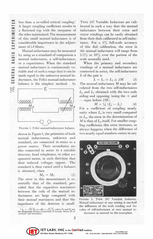
.1\ 1u tual iJlductance Illa , Le measured by using 8S a s tandard of comparison a mutllal inductance, a self-inducta nce, or a capaci tance. When the standard mutual inductance is continuously ,'ari ahle and of BLlCh a range that it can be made equal 10 t1w unknO\\ll 111111ual iuductance. the Pelici IUlltual·indllctance balance is the simplest method. As
E
J l ,
M, I Ms r
).'!Gett!! I. Felid "'ut"a l_;nd"ct.~ halance
sho\\11 in Figure I, the primaries of both lIIut\lal indm: tanees, unkno ..... n and standard. are connected in scries to u I)()\\er source. Their 5CCOll(larics are also connected in series to a suitable oete!!tor, head teJephoLle5, or other a·c 0l>crated met.er, iu II lIch (Iirectioll thai Iheir illlluced \oltages oppose. The s tandard is then \ariell until a balancc is obt ai ncd, whcll
.M \ = ,\1.~ (2) The error in this measurcnwut is e!'senlilllly that of the standard , provided thai the capaciti ve reactances betw«n the coils of the mutual ioductance!! are large L'OIUJlured \1 ith Iheir mutual reactaoces and that the impedance of the deteclor is small.
'''' - .. /li~. or .... , ... vr.L.\ ~I ... he,e 0. ... ~ DJ ~ u.. d .......... LocI ..... v-ipooeo '" "00"1' 'ac,.,.. II) 01 .,.ha..-, ... d_ •• ..,..
2
Tn-E 107 Variable Indur-tors are calibrated in such a wa y that the mutual inductance bct\lcen their rotor and sllllor windings can be ell!!.ily o!Jtaine,1 Crom their dials ('a librated in self·induc· tance. For a 1% full-scale accuracy of this dial ca libration. the error in the mutual induciance will range from 2.5% to 10% over the portion of the !wale normally used.
When the primary and secondary windings of 8. mntual inductance are connected in series. the self-ind uctance L of the pair is
L '"" L t + L2 ± 2M (3) The mulual induclatJce J\1muy he calculated from the two self·inductances La and L. ohtained "ilh the two coils Hiding and opposi ng (using the + and - si~nll berore 2M),
M s J~ (L~- L.) (4) For a coefficient of conpli ng nearly unil y where L. is very smH II compared to L ... the error in the determination of M is that of L. itself. For smnller coup· ling I'OCfficients this error increases, as ah .. a)l~ happens II hen the differcnce of 1\\0 nearly e(I'IalnlllObeNi en tcrs in an)
FIGua!!. 2. TYl' !!. 107 VariaMe Inductor. Mutual inductance at any !etting is onc.half the difference of {he .calc reading .nd tbc .. aloe of k lf·illl.loetaoce ,111 l:ef O motual in-
duc tanee &I entered on the lIan,erlue
IET LABS, Inc in the GenRad tradition
534 Main Street, Westbury, NY 11590 www.ietlabs.com
TEL: (516) 334-5959 • (800) 899-8438 • FAX: (516) 334-5988

-
-
formula . For exa mple. when K = 0.1 and L, = LEt the error .... ,ill be increased fivefold . The measurement of self·in· ductance may Le made 011 a Tn-!!! 650·A Im peda nce Bridge with 811 error of 2 j.th or 2% and 011 a TYPE 667·A Tnductance Bridge wil li an error of O. J ,uh or 0.2%. The errors \~hich occur ill in ductance measurements .... ere discussed in considerable detai l ill the General Radio Experimellter (or March, 193-LI The TYP E 293 ·1\ Universal Ilridge may also be used with resulwlIl crrors which lie between those of tbe o ther Lridgcij mentioned. In brid ges haviug a decade ratio arm, CrOIll the se ning of ' \lhicb the self.inductance is calculated, such as t be TYPE 667·A and Tn- I:: 293-A Bridges. the illcrease iu I.he error 8S the two separate bridge ba lances approach one auother is minimizcd if oTle ra tio arm i8 kept fixcd and the change in balauce taken up by minimum change8 in the other. The error is then that of thc change in resistance of the decade ratio arm.
){utual induc tance ma y be (.'Ompared with a self-induc tance on the Campbell mutual·inductance bridge sbo\\'n in Figure 5.
AL" - IJLN M - (5)
A + 11
The self-inductance Dr of the \\ indin g
FIGURE 3. TYPE 650·1\ Imped i llce Bridge
3
,-------E-------,
FIGUR K 5. Th", Carllpl", 11 l\I"\lIal·l"u"clMIce Bridge
connected inlo the bridge arm 1lI1I y bc mcasured by removing the o ther \\ illil . ing Crom the detector circuit . Denoting t hese bridge readings by primes.
U' - A - 8 A'
M ~ L,v (6) A+ IJ
B'- 8 A + B L,v
ir A ,. A' (7)
Such measuremCll ls are easil) maJc on the T\"l'E 667·A LnJucta nce Bridge by -connecting olle \\ indillg of the mutual ,..
Z inductance to (he unkno\\ II terminals c: and the olher wi nding in serie8 with ,.. lim detector. The errOfll arc slightly ::a
-<
• < o
><
z o
FICURE 4. Tn·1!. 667.'\ Inductance Bridge 00
IET LABS, Inc in the GenRad tradition
534 Main Street, Westbury, NY 11590 www.ietlabs.com
TEL: (516) 334-5959 • (800) 899-8438 • FAX: (516) 334-5988

= = -~
,-------E-------,
FIGl1RK 6. The Cfl.ccy FO!tcr \lutulll-lmluct ll l1 00 Uri<lge
less Ihnll for the pre\,jous case because for a given mutual inductance the dif-
feTCllce between the two bridge set· tings iii reduced by at least It factor of three and there is a greater chance of keeping boUI the bridge balances wit hin It single decade setting l(lwcr than the highest onc used.
A capacita nce may be llsed a8 a s tandard for comparison with an unknown mutual imluctu llce on the Carey Foster mutual-inductance hridgeshown in Fi gure 6.
(8)
The resis Lallce P includes thai of tbe \\ imling cOlUlcc led in that orlll, which is somewbat difficult to obtain. This bridge circuit may be set up on the T\TI'E 293-A Universal Bridge, using 8S a capacitance sLnlldard a suitable Tn>E 509 Mica Condenser.
- H. F. Fn;w
NEW WAVE FIL TERS • THE R E is a stead y demand for wave filters offeriug a moderate amount of diserimiuation hetween the dcgired and undcgired frequeucici and having a modcra te sharpness of cUloff. For sOUle years the General Hadjo Company has been supplying 'fYl'E 330 Fillers for general-purpose laboratory use. For 11 numlrer of uscs, ho\\ e\-cr, a sharper cutoff is required, aud afler a considerable periot.l of supplying in di vidually·de igllC"d filters for purtieular applica tions, the TYPE 830 Filter is offered 8 S a stock item.
1n Jiscussing fi lter performance the quantities of interest are usually the sharpness of clItolf or, more briefly, the "sbllrpness," and the " discrimination" or Jilferencc between the insertion loss iu decibels for the wanted and unwanled fr equencies. For certain applica tiOllS, peaks in the altenuatiOll curve are important for the suppression of particular frequencies or harmonica.
4
A filt er for general al.)ll ica tioll , howe ver, should be designed 80 that in the vallcys between the peaks the filter never gives less thall a certai n required Htlenuation. Prom tbis sta ndpoint tbe height of the lowes t vn lley measures the " discrimination," and if there is more than one va lley the best Jesign will make t.hem all of the same height. Haviug defined the " discrimi nation" as the minimullI va lley height, the "sharpness" caD be defined a8 the (requency ratio in which the discrimination is obtained. Both these (luantitie8 are indicateJ in the typical filter characteri8tic of Figure I .
Por certa in applications the Ulost important coosideration is sharpness of cutoff. For other applications a wide frequency loten -al is avai lable for the trans ition (rom the pan band to the alleuuation region, but considerable discrimioation is required bet""eell frequeucies in the two regrous. The coo-
IET LABS, Inc in the GenRad tradition
534 Main Street, Westbury, NY 11590 www.ietlabs.com
TEL: (516) 334-5959 • (800) 899-8438 • FAX: (516) 334-5988
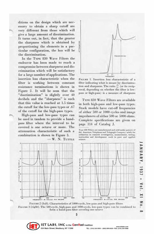
-dilioos on the design which are nccessary to obta i.n a sharp cu toff are very di lTereot (rom those which will gil·e 11 la rge amoun t of discrim ina tion. It turns out, in (act , that tbe greater the sharpness which is obt ained by proport ioning the clements in a pM ticular configuration, the less will he the discri minat ion.
I n the Tn E 830 Wave Fill ers the endeavor has bee n Illude to reach a com promise bet weeu sharpncSI! and d iscrimination which will be satisfactory for a large number of applica tioll s. The insert ion \OS8 characteristic when the fil ter is working between cons tant resistance terminations is showlI in Figure 2. Jt will be seen that the " discrimi nation" is sli ghtl y over 40 decibels aud the "sharpness" is such that this va lue is reached al 1.5 limes lhe cu torr (or the IO""pass type8 or .67 of the cutorr (or the hi gh.pass t.ypes.
High.pass and low.pass types call be used in tandem to provide a band · IlB.SS fi lter ",here tbe interval to be covered is one octa ve or more. Tbe attenua tioll characteristic of 811Ch a combination is shown in Figure 3.
- W. N. 'fUTIL E
•
, •
•
•
! •
•
· • • - - - -
I j , ,
,. f • • au""..,.
FICUMK I. In&erlion losa c1Hm,cl c ri~ , ic of a filter indicating ,,·h. 1 it I" .,au l l,)" • .liilCrimina. lion . nd sharpnetil. The ra tio r; (or ill rlldp. rocal, .Iel»ending on whethcr ,(Ie filter ill 10 .. ' l,uM or high,pIIH) i, II ",ell~ ure of ~harl'" eiWI
T"PE 830 Wa \' e Filters are available in both high.pas8 and \ov..pass types. Slock models have eut·orr frequencies of cither 500 or 1000 cycles and image im pedances of either 500 or 5000 obms. Complete specifica tions are given on page 114 of Catalog J. T,,,,, 830 Fille .... e "'Obul.«u .... ond ... M uDd .... , .. ,.", . uf 1~~ A_.ica~ T.le',bo ........ Telo-t •• ph C ..... p.n1 .., •• 11 f, .. ",m .... Moa , • ..,.. ... h In_,'p"",,. _~'. """.~. 1 • •• ..-..... ..... _10..-, ,..ot\ I. I""~ ..... oI'P11eol
""""" .... ·
" • f-
• .J\ ,
· , , ·
•
· • · - - - -........ OOCY ...... «u .. _ .. c.oo
F,GUHI: 2: ((,,/,). Charnclt:ri~ l iCil or !OOO-cyd.,. l"w-l' ~eI! ut,,1 hig h_l.a~@ mlUll FICURE 3 (rig '"). The 5O(l.f'yclc, high ' I'I' iIII and IOOO-t:ycle. 1ow-I 'uU In_ CUll I,,: com l,inl"! 10
r.)rm a Im,,, I-I,,,&ti fi lh'r (:over, ,,S one oel u,'"
5
,. Z c: ,. '" -<
< o
><
z o
IET LABS, Inc in the GenRad tradition
534 Main Street, Westbury, NY 11590 www.ietlabs.com
TEL: (516) 334-5959 • (800) 899-8438 • FAX: (516) 334-5988

= = ... '"
A HANDY VOLTAGE DIVIDER
.1 N B U I L 0 I N G speeio lizctl laboratory C(l uiplIlCII I and ill circuit developlIlellt "ork, the engineer often needs un iuexpclIsivc. com pact . and easily adjustable volLoge divider (or supplying plate Dud grid voltages to vacuum lubes. Ln several recently-developed General nadia inslrumcllts, the uni ts shown in tbe accompanying photograph have been used (or this purpose and have proved 80 useful Ihat they are 00 .... olTered for general sa le.
Tbe resistance winding and tbe moulded bakelite forms are identical in construction with those used in TnE 471·A and TWE 314-A Hhe<wllatPotentiometers. Three adjustable rOla· ry contacts are provided, each covering one-third of the total resistance. Adjustments are made by loosell ing a thumbscce\\ and movinl,{ the arm to the desired (,osi tion, after which the adjustment is locked by lightening the thumbscrew.
Ty pe 'rollli Ucsisumce
IM-\ 5,000 11 UH-A 10,000 11 151-A 20,000 11
154-8 50,000 11 154-8 100,000 11 lS-l-8 200,000 11
6
SPECifiCATIONS Power Dissipation : TYPE 154.A, 6
walls; TYPE 15·~·B, 12 walls. Accuracy of Resistance : ± 10%. Mounting: Standard 3·bole; see ac·
companying sketcb. Dimensions : TYPE lS'~·A, lYs incbes
(maximum diameter) x 1~ inches (height). TYPE 154·B, 37'8 incbes (maximum diameter) x 231 inches (height) .
Net WelEht : TYPE 154.A, 6 ouncC8; TYPE 154-B, 8 ounces.
Code Word Price
DlVIDAIOIY $6.50 OIVIDBDAT 6.50 on' locAl'g '.50
OIVIDIi:YRK 8.50 OIVlDFACT 8.50 OU'lDGIRL 8.50
IET LABS, Inc in the GenRad tradition
534 Main Street, Westbury, NY 11590 www.ietlabs.com
TEL: (516) 334-5959 • (800) 899-8438 • FAX: (516) 334-5988
A WIDE · RANG E R·F CHOKE
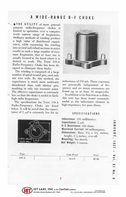
.THE UTI LITY of most general. purpose radio· frequency chokes is limited to operation o\'cr a compara. tively narrow range of frequencies. Ordinary methods of winding produce Ii high value of distrilmlcd capaci. tance, while separating the winding into 8cweral individual sectiolls in series results in such a large number of resonant frequencies that at least ooe is usually loca ted in the band where it is desired to work. The TyrE 119-/\ Radio-Frequency Choke has been designed to e limin ate these faults.
The winding is composed of a large number of spiral. wound pies, each only ODC wire wide. By this method, the capacitance is much more uniformly distributed than with tbicker pies. resulting in only one resonant point. The efTeclil'c capacitance is ex tremely
..... low, 80 that the choke is use ful at fairly hi gh radio frequencies.
The specifications for 'l'vN; 119-A Radio.Frequency Choke ure lis ted below. It will be noted that tile capacitance of 2 j.lp.f is ex tremely 10 .... for a n
11 9_A
1
in duc tance of 250 IIIh . Thcsc cons ta nt s IIrc practically indepe ndent of {reo (Iuener and no minor resonances a re found up to at least 50 megacycles.
In addi tion 10 its {unc tion as a choke. Lhis unit bas been found ex tremely useful as the inductance e leme nt In
hi gh.impedanre low.pass filters.
SPECIFICATIONS
Indu ctance : 250 millihenrys. Capacitance : 2 p.p.{ .
D· C Resistance : 450 ohms. Maximum Current : 60 milliamperes. Dimensions : Base, l~ x 1% inches;
height, IYs inchcs, o\"cr ·a ll . Mounllng : See sketch. Net Weight : 3 ounces.
Code Word
IMACE
P rice
' 1.50
-... z c: ... '" -<
• < o
z o
IET LABS, Inc in the GenRad tradition
534 Main Street, Westbury, NY 11590 www.ietlabs.com
TEL: (516) 334-5959 • (800) 899-8438 • FAX: (516) 334-5988
= = "" =
MISCELLANY .AMONG RECENT VISITORS to the General Radio Laboratories was Dr. Georg Keinath , Director of the [nst rumcnt. Lahoratories of Siemens Ilnd I-Ialske. Dr. Keinath is the author of "Die Technik E lectrische Messgeriilf'," a well-kn own lexi on electrica l measuring ins lrumenlii.
.THE " R. M. A. ENGINEER , " published by lhe Engineeri ng Division of the Radio Manufacturers' Associa tion made its first appearance with the Fa ll Meeting of the lRE at Rochester. This publicAtion, which wi ll carry s tandimlization reports and similar (lata, as .... ell as technical articles, will be issued tbrce times a year. Voio,me 1. No.1 is an achievement of which the board of editors lIlay be proud.
• PERIODICALlY it becomes necessary to revise the Experimenter and catalog mailing lis t. Shortly after you receive this issue of the E;t:peri. /IIcrller, a post card "subscription " renewal form will reach you. The re\'ised G.G mail ing list wi ll be made up from the returns received from these canis.
[0 order 1.0 insure yonr name remain· ing on the list. the return card should be filled in eomplel.ely and malled promptly.
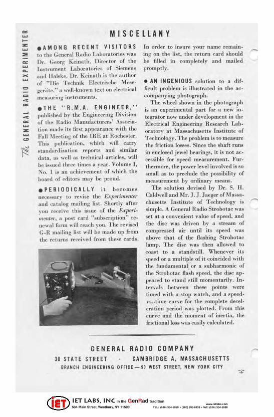
• AN INGENIOUS solution to a dif. ficult problem is illustrated ill the ac· companying photograph.
The wllee! shown in the photograph is an e~perimental part for a new in · tegrator now under development in the Electrical E ngineering Research Lab· oratory at :Massachusetla Institute of Technology. Tbe problem is 1.0 measure the friction losses. Since the shaft runs in enclosed jewel bearings. it is not accessi ble for speed measurem ent. Furtbermore, the power level involved is so small as 1.0 preclude the possibility of measurement by ordinllry means.
The solution devised by Dr. S. U . Caldwell and 1Hr. J. J. J aeger of M assa· chuselt s Institute of Technology is simplc. A General Radio Strobotac was se t at a convenient value of speed, and lbe disc was dri ven by a stream of compressed air until its speed was above that of the flashing Strobotac lamp. The disc was then allowed to coaSI to a standstill. Whenever its speed or a multiple of it coillcided with tlle rundamental or a subharmonie of the St robotac fla~h speed, the disc ap· peared to stand still momcntarily. Intervals between these points were !"illled with a SlOp watch, and a spee(lvs. -time curve for the comple te dccel· eration period was plotted. From this curve and the moment of inertia, the fri ctional loss was easily calculated.
GENERAl RADIO COMPANY 30 STATE STREET CAMBRIOGE A, MASSACHUSETTS
BRANCH ENGINEERING OFFICE-90 WEST STREET. NEW YORK CITY
-
IET LABS, Inc in the GenRad tradition
534 Main Street, Westbury, NY 11590 www.ietlabs.com
TEL: (516) 334-5959 • (800) 899-8438 • FAX: (516) 334-5988