


![002 CBB_T01_E2 Principle and Implementation of CDMA Spread Spectrum-27 [Compatibility Mode]](https://static.fdocuments.us/doc/165x107/577d27591a28ab4e1ea3b08e/002-cbbt01e2-principle-and-implementation-of-cdma-spread-spectrum-27-compatibility.jpg)


Languages
Pages
Legal


EC744 Wireless Communications Spring 2007
Mohamed Essam Khedr
Department of Electronics and Communications
Spread spectrum, CDMA, OVSF, MC-CDMA
2
Spread Spectrum Communications - Agenda� Basic principles and block diagrams of spread spectrum
communication systems� Characterizing concepts� Types of SS modulation: principles and circuits
– direct sequence (DS)– frequency hopping (FH)
� Error rates� Spreading code sequences; generation and properties
– Maximal Length (a linear, cyclic code)– Gold– Walsh
� Orthogonal Variable spreading factor � Multicarrier CDMA
3
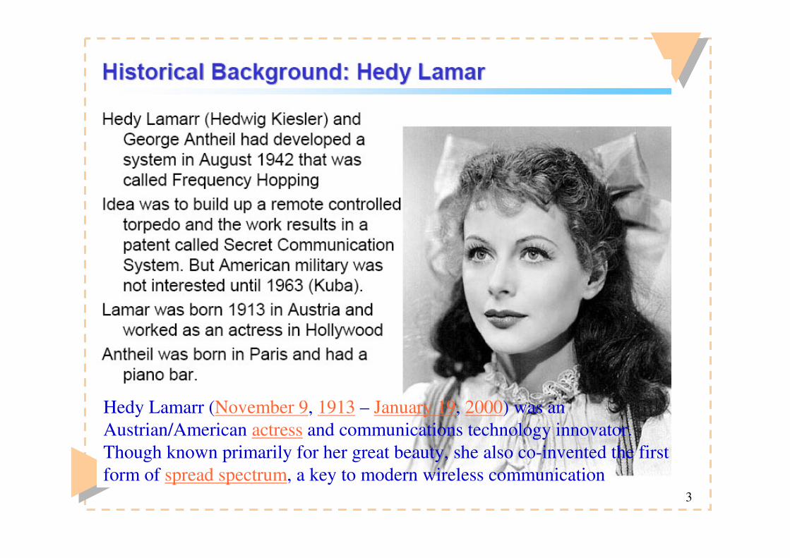
Hedy Lamarr (November 9, 1913 – January 19, 2000) was an Austrian/American actress and communications technology innovator. Though known primarily for her great beauty, she also co-invented the first form of spread spectrum, a key to modern wireless communication

4

5
Direct Sequence Spread Spectrum (DS-SS)
� This figure shows BPSK-DS transmitter and receiver (multiplication can be realized by RF-mixers)
DSCDMA is used in WCDMA, cdma2000 and IS95 systems
2
22av av
AP A P= � =
spreading
6
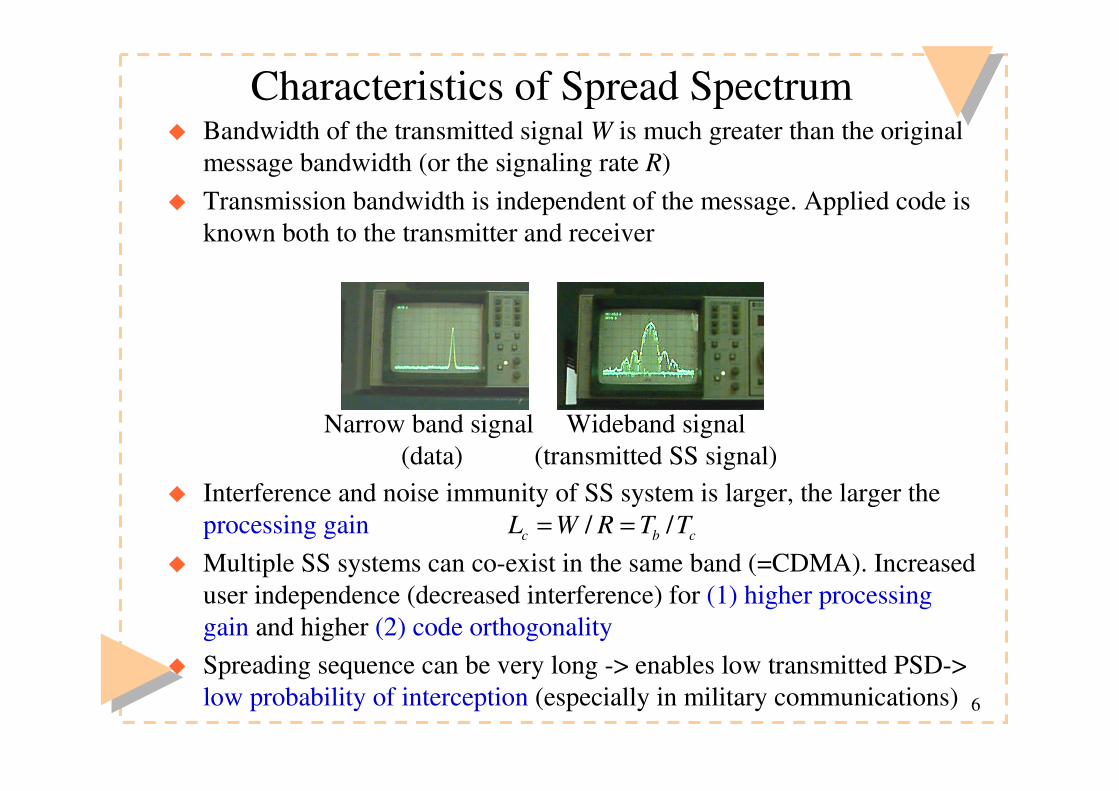
Characteristics of Spread Spectrum � Bandwidth of the transmitted signal W is much greater than the original
message bandwidth (or the signaling rate R)� Transmission bandwidth is independent of the message. Applied code is
known both to the transmitter and receiver
� Interference and noise immunity of SS system is larger, the larger the processing gain
� Multiple SS systems can co-exist in the same band (=CDMA). Increased user independence (decreased interference) for (1) higher processing gain and higher (2) code orthogonality
� Spreading sequence can be very long -> enables low transmitted PSD-> low probability of interception (especially in military communications)
Narrow band signal (data)
Wideband signal(transmitted SS signal)
/ /c b cL W R T T= =

7
Direct Sequence Spread Spectrum Using BPSK Example

8
ApproximateSpectrum of DSSS Signal

9
Characteristics of Spread Spectrum (cont.)
� Processing gain, in general
– Large Lc improves noise immunity, but requires a larger transmission bandwidth
– Note that DS-spread spectrum is a repetition FEC-coded systems
� Jamming margin
– Tells the magnitude of additional interference and noise that can be injected to the channel without hazarding system operation. Example:
, 10/ (1/ ) /(1/ ) / , 10 log ( )c c b b c c dB cL W R T T T T L L= = = =
[ ( ) ]J c sys despM L L SNR= − +
30dB,available processing gain
2dB,margin for system losses
10dB,required SNR after despreading (at the RX)
18dB,additional interference and noise can deteriorate
receive
c
sys
desp
j
L
L
SNR
M
==
=
� =
d SNR by this amount
10
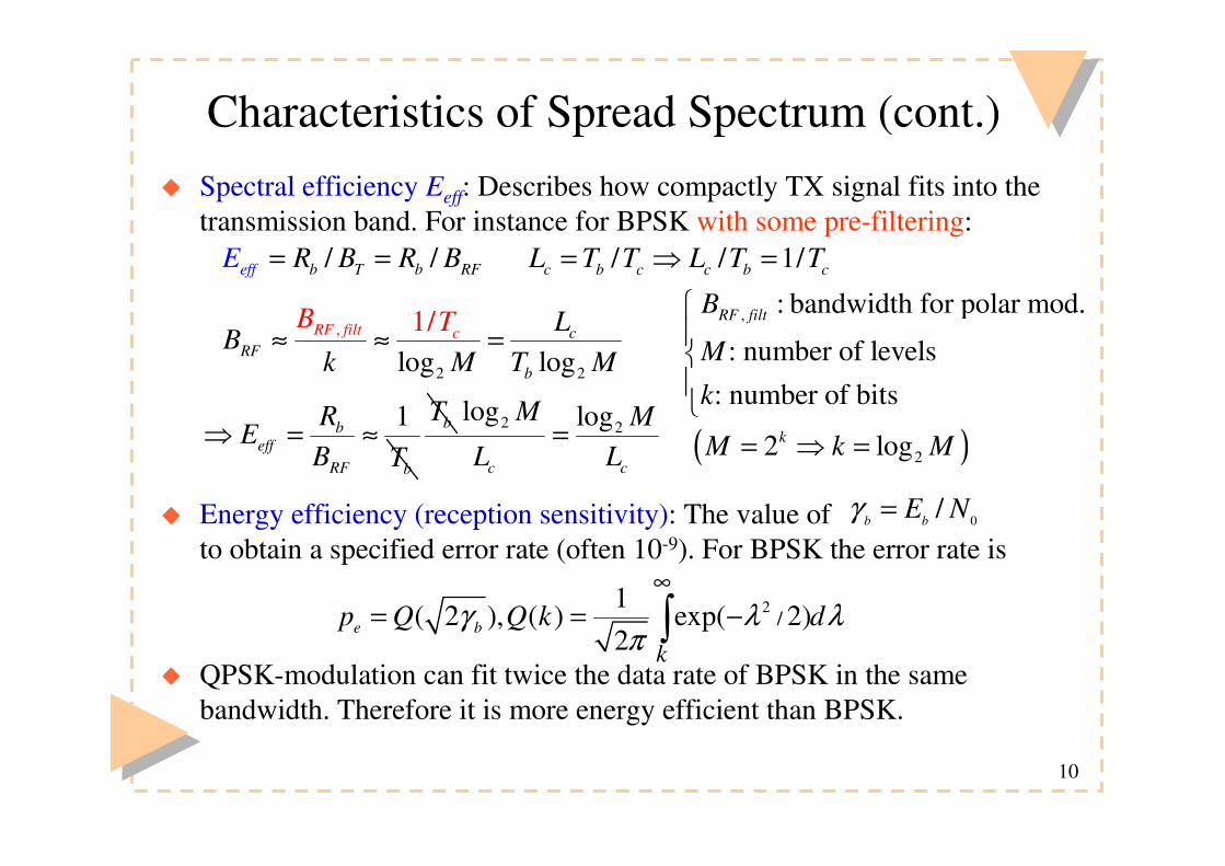
Characteristics of Spread Spectrum (cont.)� Spectral efficiency Eeff: Describes how compactly TX signal fits into the
transmission band. For instance for BPSK with some pre-filtering:
� Energy efficiency (reception sensitivity): The value of to obtain a specified error rate (often 10-9). For BPSK the error rate is
� QPSK-modulation can fit twice the data rate of BPSK in the same bandwidth. Therefore it is more energy efficient than BPSK.
/ /b T b Fff Re R B RE B= =
,
2 2log log1/RF filt c c
RFb
B T LB
k M T M≈ ≈ =
/ / 1/c b c c b cL T T L T T= � =
1beff
RF b
RE
B T� = ≈ bT 2 2
log log
c c
M ML L
=
0/b bE Nγ =
2/
1( 2 ), ( ) exp( 2)
2e b
kp Q Q k dγ λ λ
π
∞= = −�
( )22 logkM k M= � =
, : bandwidth for polar mod.
: number of levels: number of bits
RF filtB
M
k
�����

11
A QPSK-DS Modulator
� After serial-parallel conversion (S/P) data modulates the orthogonal carriers
� Modulation on orthogonal carriers spreaded by codes c1 and c2
� Spreading codes c1 and c2 may or may not be orthogonal (System performance is independent of their orthogonality, why?)
� What kind of circuit can make the demodulation (despreading)?
2 cos oP tω
2 sin oP tω
1( )c t
2 ( )c t/S P( )s t( )d t
i
q
Constellationdiagram
QPSK-modulator
2 cos( ) and 2 sin( )o oP t P tω ω

12
DS-CDMA (BPSK) Spectra (Tone Jamming)� Assume DS - BPSK transmission, with a single tone jamming (jamming
power J [W] ). The received signal is
� The respective PSD of the received chip-rate signal is
� At the receiver r(t) is multiplied with the local code c(t) (=despreading)
� The received signal and the local code are phase-aligned:
( ) ( )1 0 0( ) 2 ( )cos 2 cos( ) 'd dr t Pc t T t tt J ωω θ ϕ− + + +=
( ) ( )
{ }
2 2
0 0
0 0
1 1( ) sinc si
1( ) ( )
2
nc2 2c cr c cT TS f PT f f PT f f
J f f f fδ δ
= − + +� � � �
− + +
+
( )( )
1 0
0
( ) 2 ( ) cos ( )
2 cos '
ˆ( )
ˆ( )
d dd
d
d t Pc t T tc t T
c t T
t
J t
ω θ
ω ϕ
−− +
+ +−
=
− − = �1ˆ( ) ( ) 1d dc t T c t T ( ) ( )
( ) ( )
( ){ }
2 20 0
0
2 20 0
ˆ2 ( )cos '
1 1( ) sinc s
1 1sinc sinc
inc2
2 2
2d b b b b
d
c c c c
Jc t T t
S f PT f f T PT f
JT f f T
f
J
T
T f f T
ω ϕ− +
− + +� � � �
= − + +� � � �
+ ���������������������
F
data
Data spectraafter phase modulator
Spreading of jammer power

13
Tone Jamming (cont.)� Despreading spreads the jammer power and despreads the signal power:
14
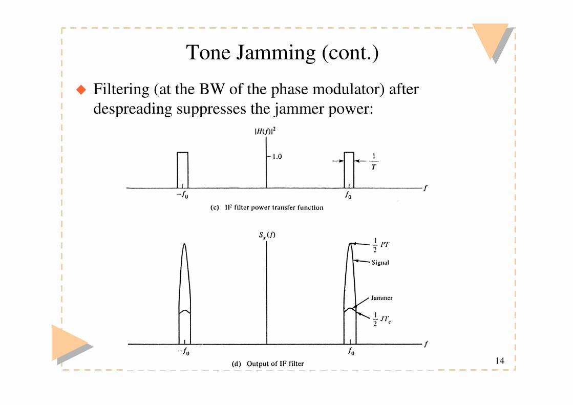
Tone Jamming (cont.)
� Filtering (at the BW of the phase modulator) after despreading suppresses the jammer power:
15
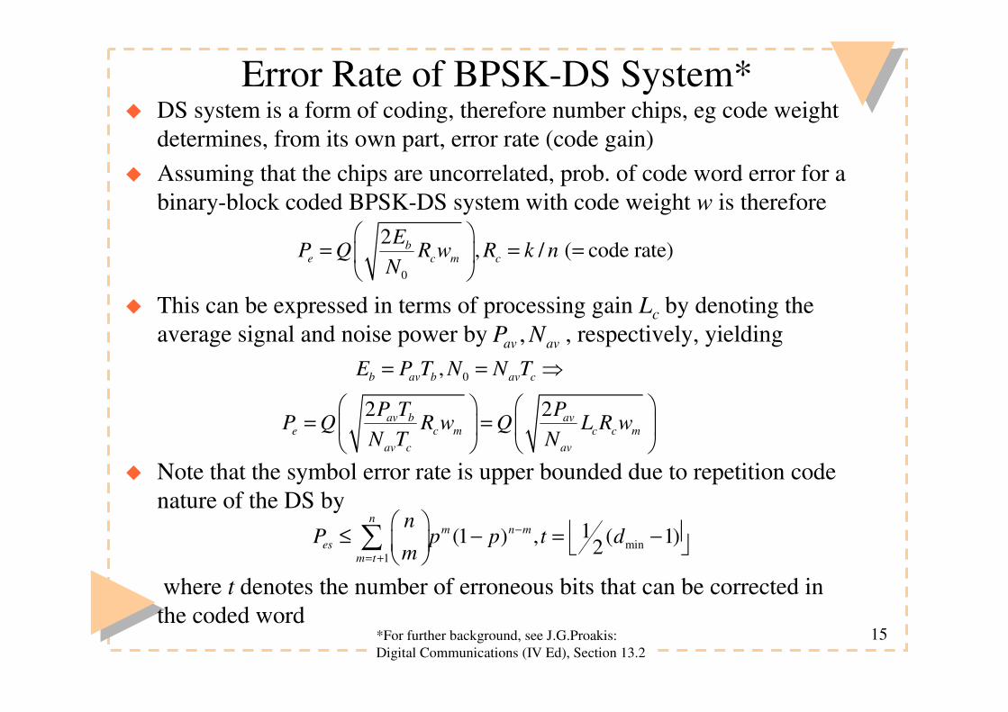
Error Rate of BPSK-DS System*� DS system is a form of coding, therefore number chips, eg code weight
determines, from its own part, error rate (code gain)� Assuming that the chips are uncorrelated, prob. of code word error for a
binary-block coded BPSK-DS system with code weight w is therefore
� This can be expressed in terms of processing gain Lc by denoting the average signal and noise power by , respectively, yielding
� Note that the symbol error rate is upper bounded due to repetition code nature of the DS by
where t denotes the number of erroneous bits that can be corrected in the coded word
0
2, / ( code rate)b
e c m c
EP Q R w R k n
N
� �= = = �
� �
0,b av b av cE P T N N T= = �
,av avP N
2 2av b ave c m c c m
av c av
P T PP Q R w Q L R w
N T N
� � � �= = � �
� � � �
min1
1(1 ) , ( 1)2n
m n mes
m t
nP p p t d
m−
= +
� � � �≤ − = − � � ��
*For further background, see J.G.Proakis: Digital Communications (IV Ed), Section 13.2

16
Example: Error Rate of Uncoded Binary BPSK-DS
� For uncoded DS w=n, thus and
� We note that and yielding
� Therefore, we note that increasing system processing gain W/R, error rate can be improved
(1/ ) 1cR w n n= =
0 0
2 2b be c m
E EP Q R w Q
N N
� � � �= = � �
� � � �
/b av b av bE P T P R= = 0 /avJ J W=
0
/ // /
b av
av av av
E P R W RJ J W J P
= =
2 //e
av av
W RP Q
J P
� �� = �
� �
17
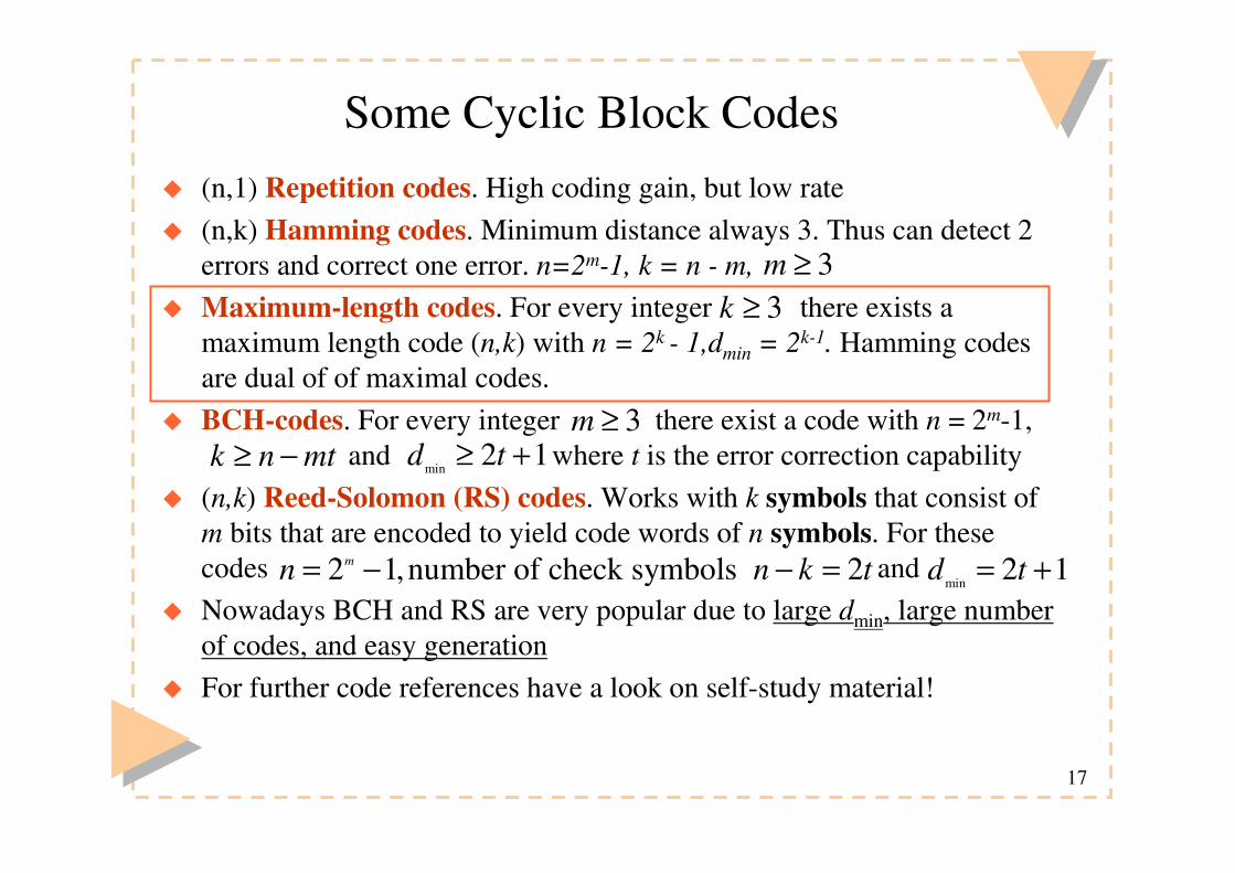
Some Cyclic Block Codes � (n,1) Repetition codes. High coding gain, but low rate� (n,k) Hamming codes. Minimum distance always 3. Thus can detect 2
errors and correct one error. n=2m-1, k = n - m, � Maximum-length codes. For every integer there exists a
maximum length code (n,k) with n = 2k - 1,dmin = 2k-1. Hamming codes are dual of of maximal codes.
� BCH-codes. For every integer there exist a code with n = 2m-1, and where t is the error correction capability
� (n,k) Reed-Solomon (RS) codes. Works with k symbols that consist of m bits that are encoded to yield code words of n symbols. For these codes and
� Nowadays BCH and RS are very popular due to large dmin, large number of codes, and easy generation
� For further code references have a look on self-study material!
3k ≥
3≥m≥ −k n mt min
2 1≥ +d t
2 1,number of check symbols 2= − − =mn n k tmin
2 1= +d t
3m ≥
18
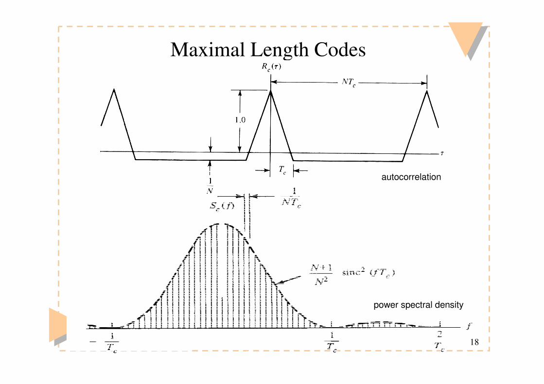
Maximal Length Codes
autocorrelation
power spectral density

19
Maximal Length Codes (cont.)� Have very good autocorrelation but cross correlation not granted� Are linear,cyclic block codes - generated by feedbacked shift registers� Number of available codes* depends on the number of shift register
stages:� Code generator design based on tables showing tap feedbacks:
5 stages->6 codes, 10 stages ->60 codes, 25 stages ->1.3x10⁶ codes
*For the formula see: Peterson, Ziemer: “Introduction to Spread Spectrum Communication”, p. 121

20
Design of Maximal Length Generators by a Table Entry
� Feedback connections can be written directly from the table:

21
Other Spreading Codes� Walsh codes: Orthogonal, used in synchronous systems, also in
WCDMA downlink� Generation recursively:
� All rows and columns of the matrix are orthogonal:
� Gold codes: Generated by summing preferred pairs of maximal length codes. Have a guarantee 3-level crosscorrelation:
� For N-length code there exists N + 2 codes in a code family and
� Walsh and Gold codes are used especially in multiple access systems� Gold codes are used in asynchronous communications because their
crosscorrelation is quite good as formulated above
=0 [0]H − −
−−
� �= � �
1 1
11
n nn
nn
H HH
H H � �� �� �=� �� �
2
0 0 0 00 1 0 10 0 1 10 1 1 0
H
� − − + − + − + ⋅ =( 1)( 1) ( 1)1 1( 1) 1 1 0
{ }− −( ) / ,1/ ,( ( ) 2) /t n N N t n N
+
+
� += �
+�
( 1) / 2
( 2) / 2
1 2 ,for odd( )
1 2 ,for even
n
n
nt n
n= −2 1 andnN
22
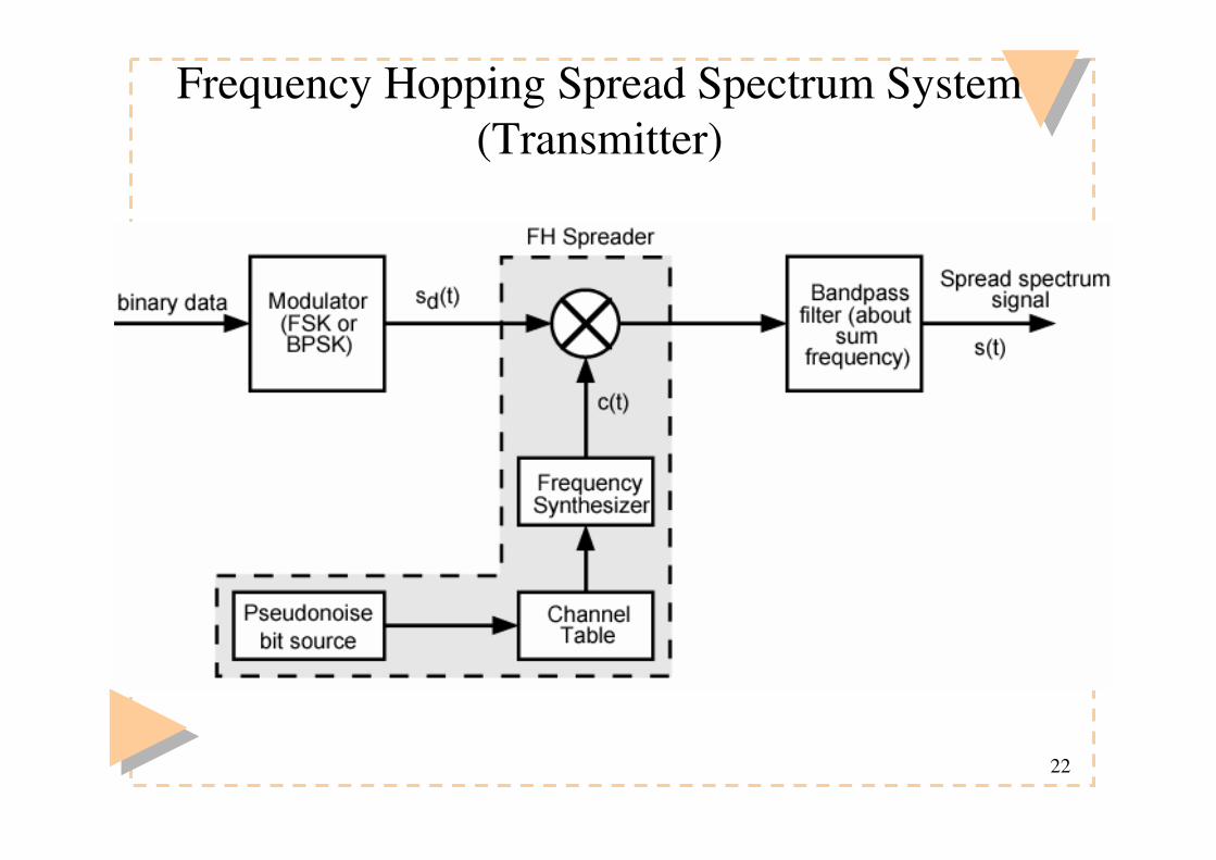
Frequency Hopping Spread Spectrum System (Transmitter)
23
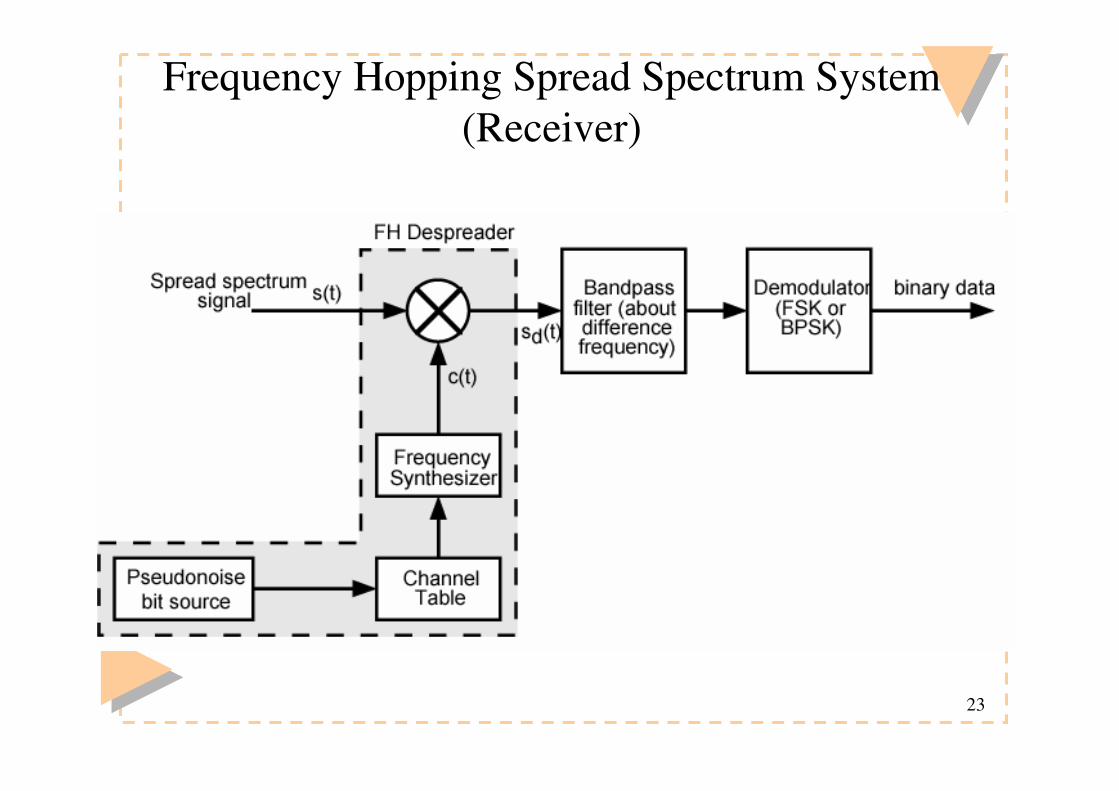
Frequency Hopping Spread Spectrum System (Receiver)

24
Slow and Fast FHSS
� Frequency shifted every Tc seconds� Duration of signal element is Ts seconds� Slow FHSS has Tc ≥ Ts
� Fast FHSS has Tc < Ts
� Generally fast FHSS gives improved performance in noise (or jamming)

25
Slow Frequency Hop Spread Spectrum Using MFSK (M=4, k=2)
26
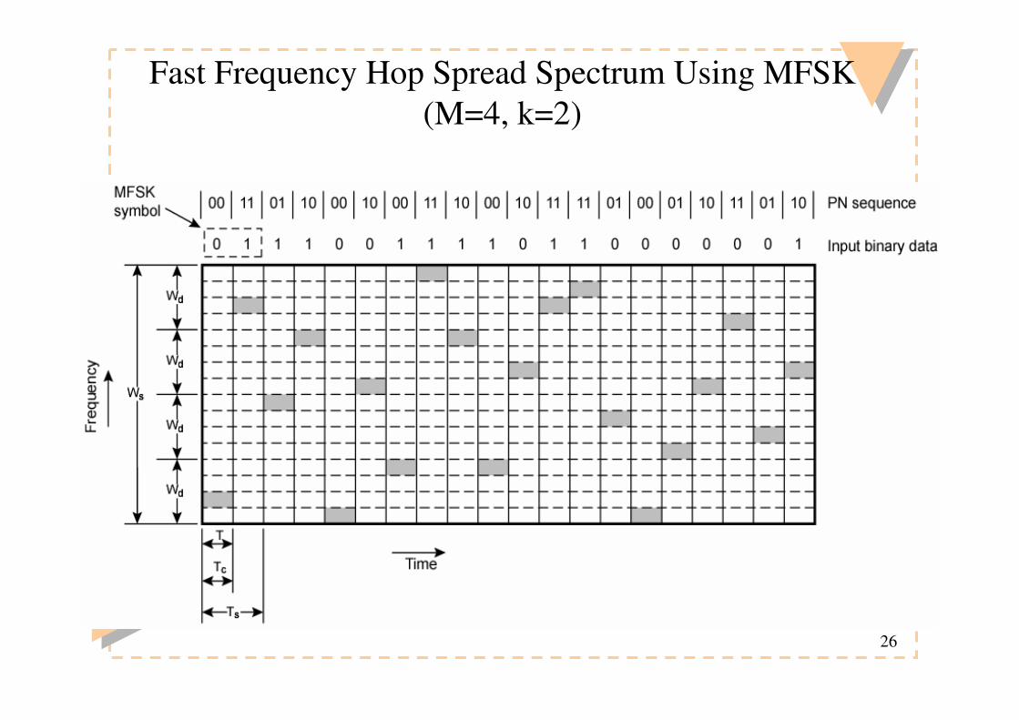
Fast Frequency Hop Spread Spectrum Using MFSK (M=4, k=2)

27
Error Rate in Frequency Hopping� If there are multiple hops/symbol we have a fast-hopping system. If
there is a single hop/symbol (or below), we have a slow-hopping system.
� For slow-hopping non-coherent FSK-system, binary error rate is
� A fast-hopping FSK system is a diversity-gain system. Assuming non-coherent, square-law combining of respective output signals from matched filters yields the binary error rate (with L hops/symbol)
(For further details, see J.G.Proakis: Digital Communications (IV Ed), Section 13.3)
( ) 01 exp / 2 , /2e b b bP E Nγ γ= − =
( ) ( )1
2 1 0
1
0
1exp / 2 / 2 ,
22 11
!
L i
e b i b b cL i
L i
i r
P K L
LK
ri
γ γ γ γ−
− =
− −
=
= − =
−� �= �� �
�
�

28
Multiple access: FDMA, TDMA and CDMA
•FDMA, TDMA and CDMA yield conceptually the same capacity
• However, in wireless communicationsCDMA has improved capacity due to
• statistical multiplexing• graceful degradation
•Performance can still be improved byadaptive antennas, multiuser detection,FEC, and multi-rate encoding

29
Example of DS multiple access waveforms
channel->
detecting A ... ->
polar sig.->
30
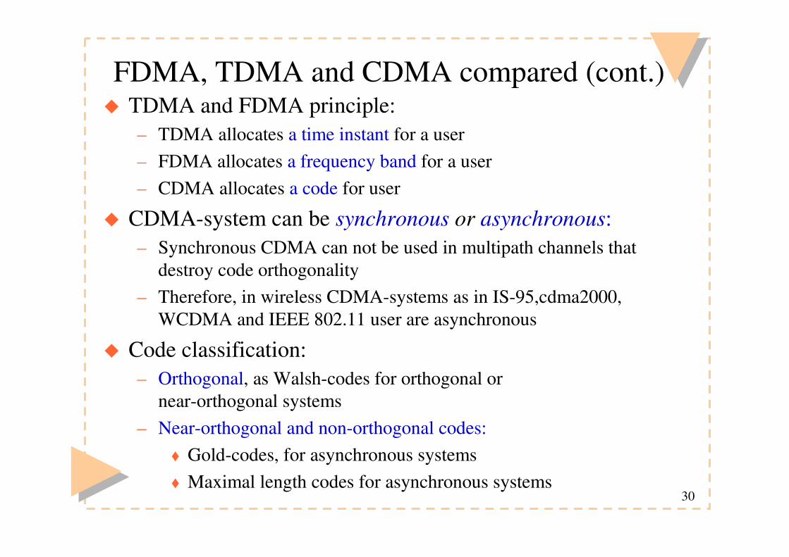
FDMA, TDMA and CDMA compared (cont.)� TDMA and FDMA principle:
– TDMA allocates a time instant for a user– FDMA allocates a frequency band for a user– CDMA allocates a code for user
� CDMA-system can be synchronous or asynchronous:– Synchronous CDMA can not be used in multipath channels that
destroy code orthogonality– Therefore, in wireless CDMA-systems as in IS-95,cdma2000,
WCDMA and IEEE 802.11 user are asynchronous
� Code classification:– Orthogonal, as Walsh-codes for orthogonal or
near-orthogonal systems – Near-orthogonal and non-orthogonal codes:
� Gold-codes, for asynchronous systems � Maximal length codes for asynchronous systems

31
Variable Data Rate Services
� Two ways to provide higher and variable data rate services:– Multi-code CDMA
� Multiple Orthogonal Constant Spreading Factor (OCSF) codes– OVSF-CDMA
� Single Orthogonal Variable Spreading Factor (OVSF) code

32
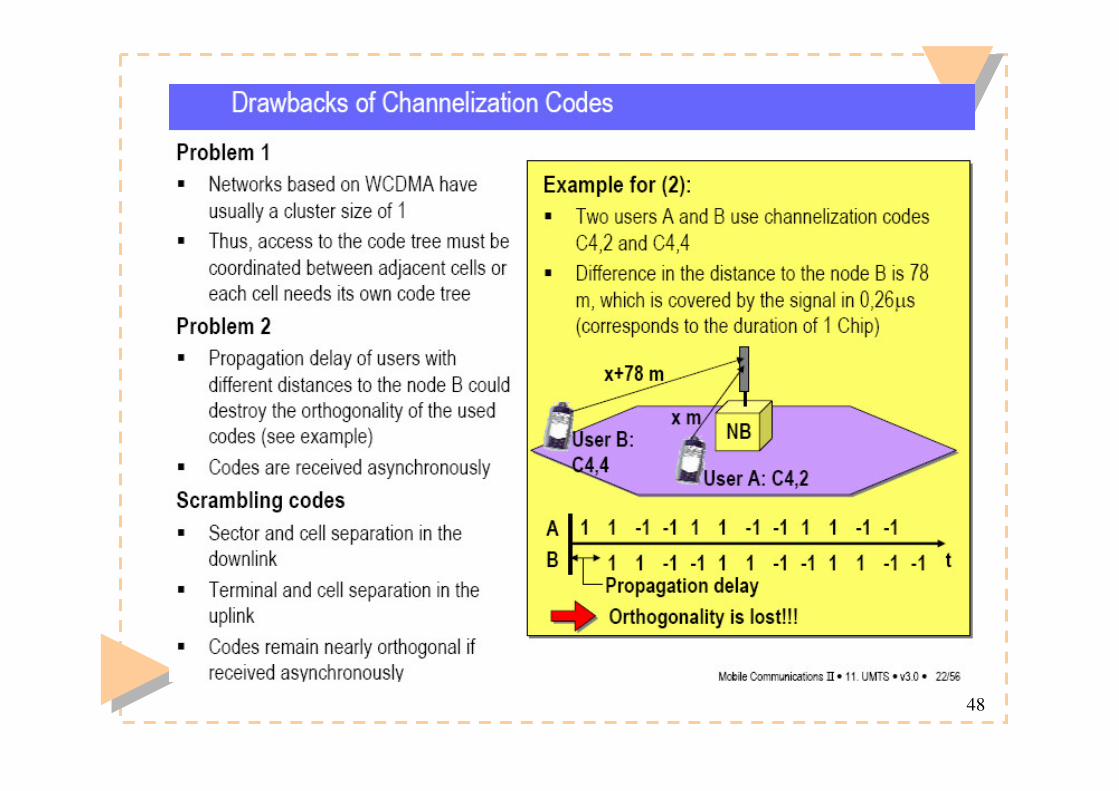
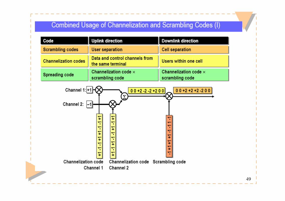
Spreading Operation� Spreading means increasing the signal bandwidth� Strictly speaking, spreading includes two operations:
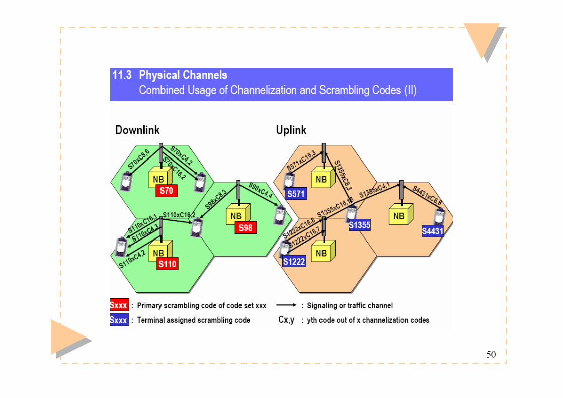
(1) Channelization (increases signal bandwidth) - using orthogonal codes(2) Scrambling (does not affect the signal bandwidth)- using pseudo noise codes

33
34
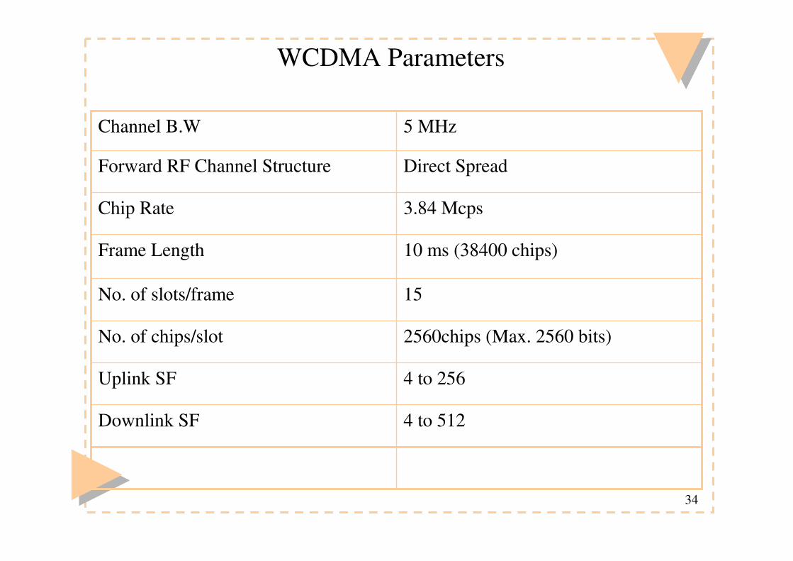
WCDMA Parameters
4 to 512Downlink SF
4 to 256Uplink SF
2560chips (Max. 2560 bits)No. of chips/slot
15No. of slots/frame
10 ms (38400 chips)Frame Length
3.84 McpsChip Rate
Direct SpreadForward RF Channel Structure
5 MHzChannel B.W

35
Codes
NOYESIncrease B.W?
Long 10ms code: Gold code
Orthogonal Variable Spreading FactorCode Family
UL: Several millionDL: 512
No. of codes under one scrambling code= SF
No. of codes
38400 chipsUL:4-256 chipsDL:4-512 chips
Length
UL: Separation of terminalsDL: Separation ofcells/sectors
UL: Separation of physical dataand control channels from same UEDL: Separation of different userswithin one cell
Usage
Scrambling CodeChannellization Code

36
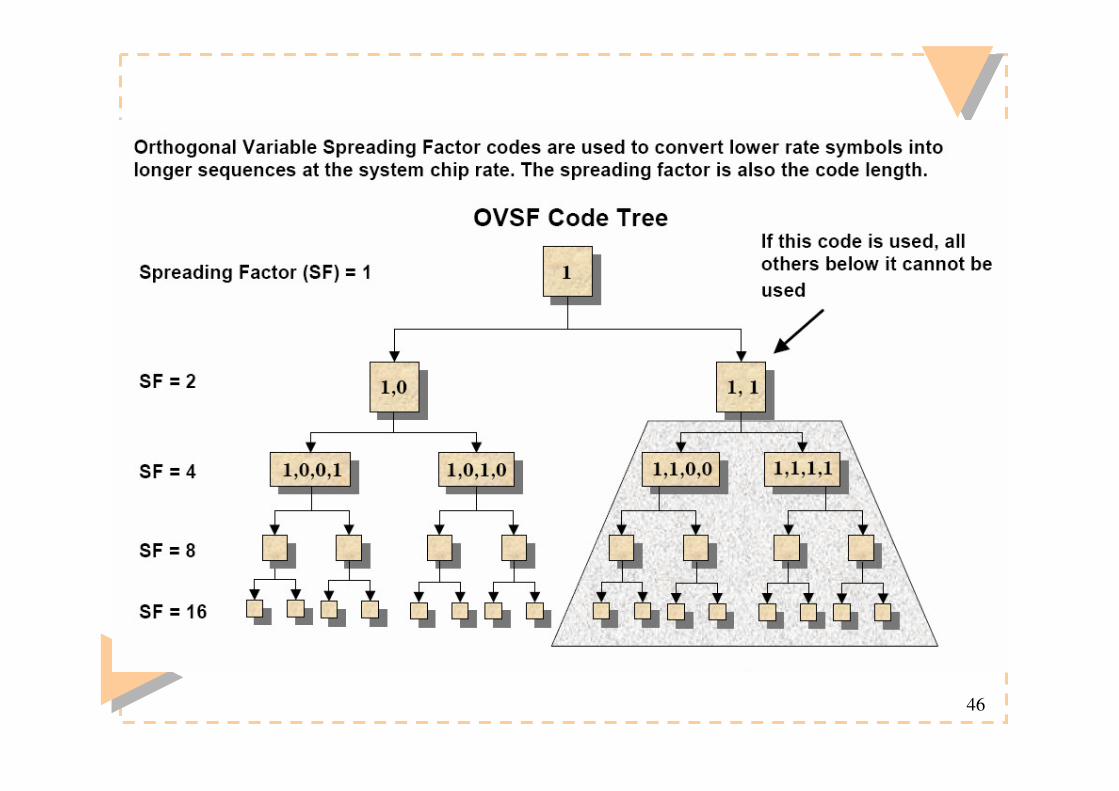
OVSF
� WCDMA is used as the radio access technology in UMTS� In WCDMA, OVSF codes are assigned to users’ calls to preserve
the orthogonal between users’ physical channels.� The data rate supported by an OVSF code depends on its
spreading factor (SF).� the rearrangeable scheme can reduce the call blocking
probability.� The drawback of the rearrangeable scheme increases the
computation overhead of the system� The nonrearrangeable schemes are considered simple and with
low system overhead for the OVSF code assignment

37
3G w
ireless systems: U
MTS
ICTP - MiramareCDMA – Technology review
Ortogonal Variable Spreading FactorCodes
Recursive rule
( )( )
1
2
2
(0) 1
(2 1) ( ), ( )( )
(2 ) ( ), ( )N N N
NN N N
C
C i C i C iC i
C i C i C i
=
− =��→� = −��
1
11
1-1
1111
11-1-1
1-1-11
1-11-1
C1(1)
C2(1)
C2(2)
C4(1)
C4(2)
C4(3)
C4(4)
38
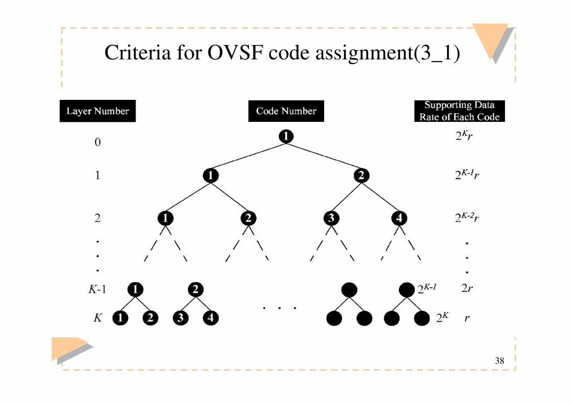
Criteria for OVSF code assignment(3_1)

39
Criteria for OVSF code assignment(3_2)
� OVSF code have three statuses: free�busy�assignable.– Free: the code has not been assigned to a user.– Busy: the code is assigned to a user.– Assignable: if and only if the code and all of its ancestor
and descendant OVSF codes in the tree are free.

40
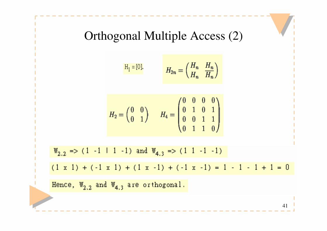
Orthogonal Multiple Access� requires synchronization among the users, since the
waveforms are orthogonal only if they are aligned in time.
���������������
������������� ���������������� ������� �
����������������
41
Orthogonal Multiple Access (2)
42
Orthogonal Multiple Access (3)
� Disadvantage of Walsh-Hadamard code:1. It have more than one autocorrelation peak , therefore need an
external synchronization scheme. 2. Cross-correlation will affect it, so it is only used in synchronized
CDMA3. Spreading is not over the whole bandwidth, instead over a number of
discrete frequency-component.

43
Why Orthogonal?
C1,1
C2,1
SF=1
SF=2
SF=4
SF=8
C4,2 C4,3 C4,4C4,1
C8,1 C8,5 C8,6 C8,7 C8,8C8,2 C8,3 C8,4
C2,2
����������������� ���� ���� ���������� ��

44
Layers in OVSF Code Tree
C1,1
C2,1
SF=1
SF=2
SF=4
SF=8
C4,2 C4,3 C4,4C4,1
C8,1 C8,5 C8,6 C8,7 C8,8C8,2 C8,3 C8,4
C2,2
������� ����������� ����� ���������� ���������������� ��� ������������������� ������

45
When non-orthogonal codes happens?
C1,1
C2,1
SF=1
SF=2
SF=4
SF=8
C4,2 C4,3 C4,4C4,1
C8,1 C8,5 C8,6 C8,7 C8,8C8,2 C8,3 C8,4
C2,2
������� ����������� ����� ������������� ���������� ��� ������������������� ������
46

47
48
49
50

51
Multi-rate Assignment Issue
C1,1
C2,1
SF=1
SF=2
SF=4
SF=8
C4,2 C4,3 C4,4C4,1
C8,1 C8,5 C8,6 C8,7 C8,8C8,2 C8,3 C8,4
C2,2
��������� ������������� ��������� ���� ��� ����
52
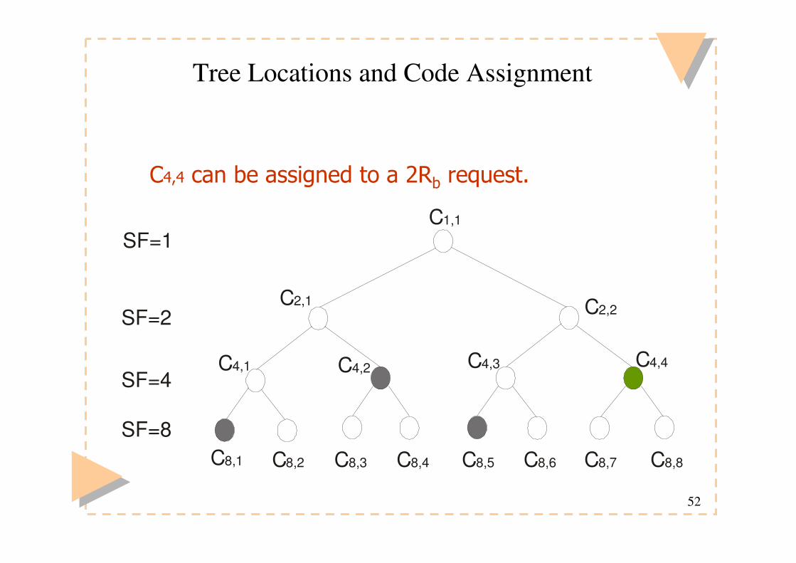
Tree Locations and Code Assignment
C1,1
C2,1
SF=1
SF=2
SF=4
SF=8
C4,2 C4,3 C4,4C4,1
C8,1 C8,5 C8,6 C8,7 C8,8C8,2 C8,3 C8,4
C2,2
����� ���� ��������� ���� ��� ����
53
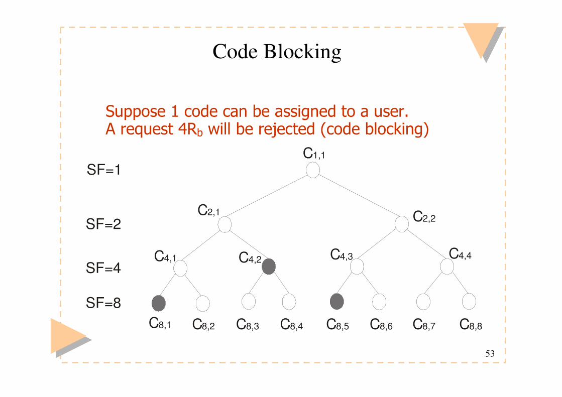
Code Blocking
C1,1
C2,1
SF=1
SF=2
SF=4
SF=8
C4,2 C4,3 C4,4C4,1
C8,1 C8,5 C8,6 C8,7 C8,8C8,2 C8,3 C8,4
C2,2
! �������������� ���� ��������� � ��������� ������� ���������"������#���������$�%

54
Multi-code assignment
� There are three dimensions when considering the code allocation:– Ordering of assignment
� Increasing or decreasing– Co-location of codes
� United or separated– Assignment of individual codes
� Four code assignment schemes are proposed
55
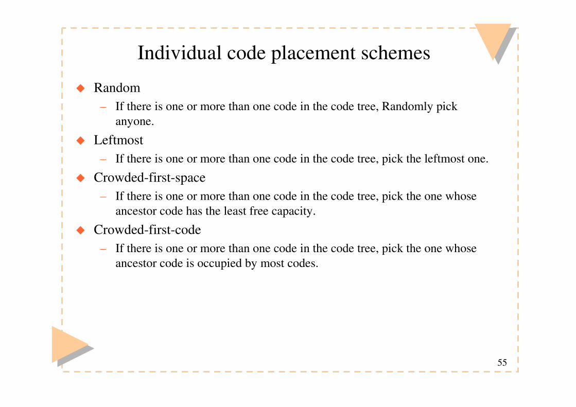
Individual code placement schemes
� Random– If there is one or more than one code in the code tree, Randomly pick
anyone.
� Leftmost– If there is one or more than one code in the code tree, pick the leftmost one.
� Crowded-first-space– If there is one or more than one code in the code tree, pick the one whose
ancestor code has the least free capacity.
� Crowded-first-code– If there is one or more than one code in the code tree, pick the one whose
ancestor code is occupied by most codes.

56
Code assignment example (one code)
� Random– Any of the candidates can be
picked
� Leftmost– C16,1 will be picked.
� ��������������� ��� ��&��'���������$���
� ������������������ ��&�����������$���
����� ������� �����
� �� ���������(���&������&�)����&�&����&�*����&�+����&��'�

57
Code assignment example (multi-code)
� Leftmost – {C8,1 , C16,3}
� ��������������� ��
�,�+�+����&���-
� �����������������
�,�+�'����&�*-
! ����������������� ���� ��������� � ��������� ����&�� ������#�������������� ������� ��������%�
���� ������������� ��������

58
Code reassignment
� When a code tree is used for long, it is sometimes inevitable that the code tree may become fragmented .
� To solve this problem, code reassignment can be conducted to move current codes around so as to squeeze a large-enough space for the request.
59
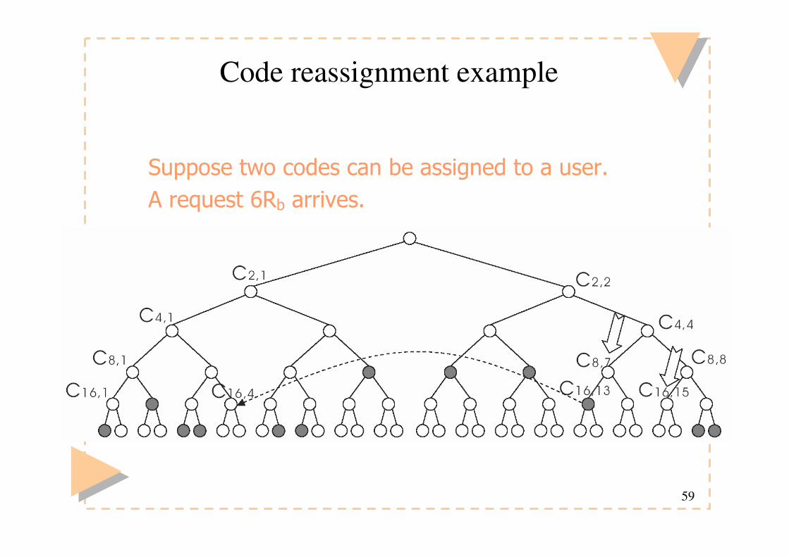
Code reassignment example
! ����������������� ���� ��������� � ����
����� ����&�� ������
60
Multicarrier CDMA
� Multicarrier CDMA combines OFDM and CDMA
� Idea is to use DSSS to spread a narrowband signal and then send each chip over a different subcarrier– DSSS time operations converted to frequency domain
� Greatly reduces complexity of SS system– FFT/IFFT replace synchronization and despreading
� More spectrally efficient than CDMA due to the overlapped subcarriers in OFDM
� Multiple users assigned different spreading codes– Similar interference properties as in CDMA

61
Outline
1 Problem Statement and Solution Considered
2 CDMA Multiple Access Schemes
– SC DS-CDMA, MC-CDMA, and MC DS-CDMA
3 Limitations of Broadband SC DS-CDMA and MC-CDMA
4 MC DS-CDMA for Ubiquitous Broadband Communication
– Advantages in diverse broadband channels
– Improvement through TF-domain spreading
5 Conclusions
62
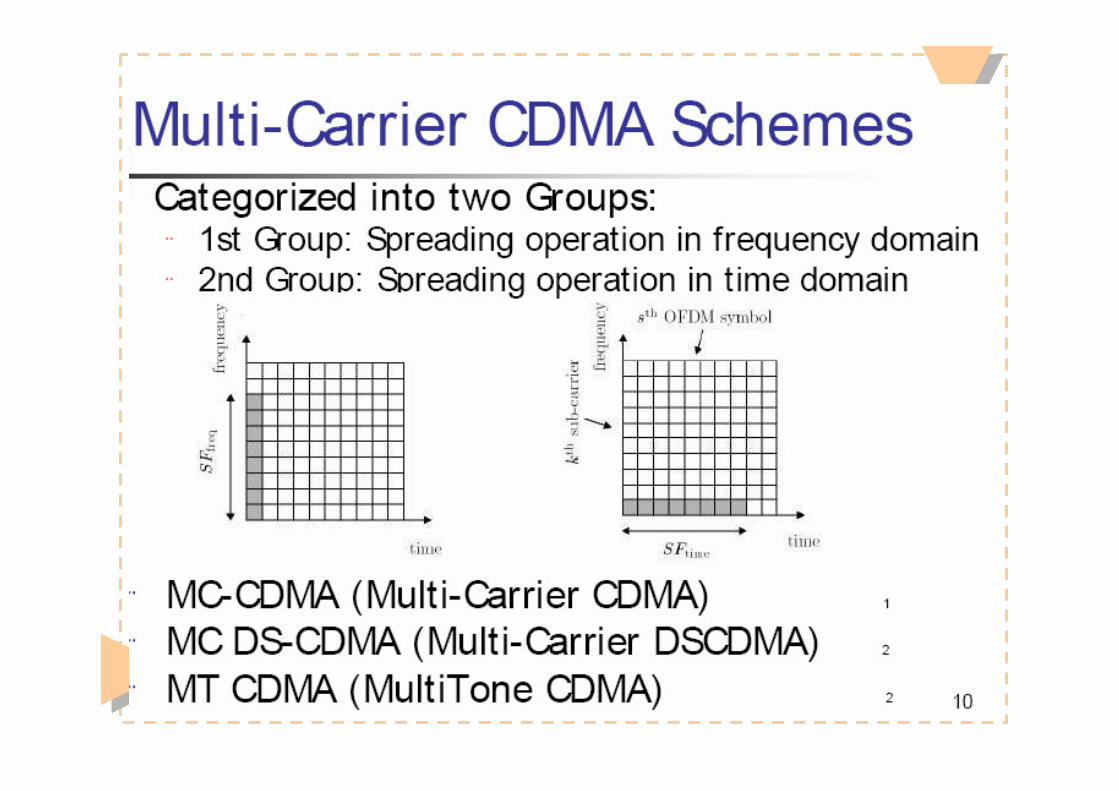
CDMA-based schemes� Can combine concepts of CDMA and OFDM� Reap the benefits of both techniques� In 1993, three slightly different schemes were independently proposed:
– MC-CDMA (Yee, Linnartz, Fettweis, and others)*– Multicarrier DS-CDMA (DaSilva and Sousa)*– MT-CDMA (Vandendorpe)
63
64
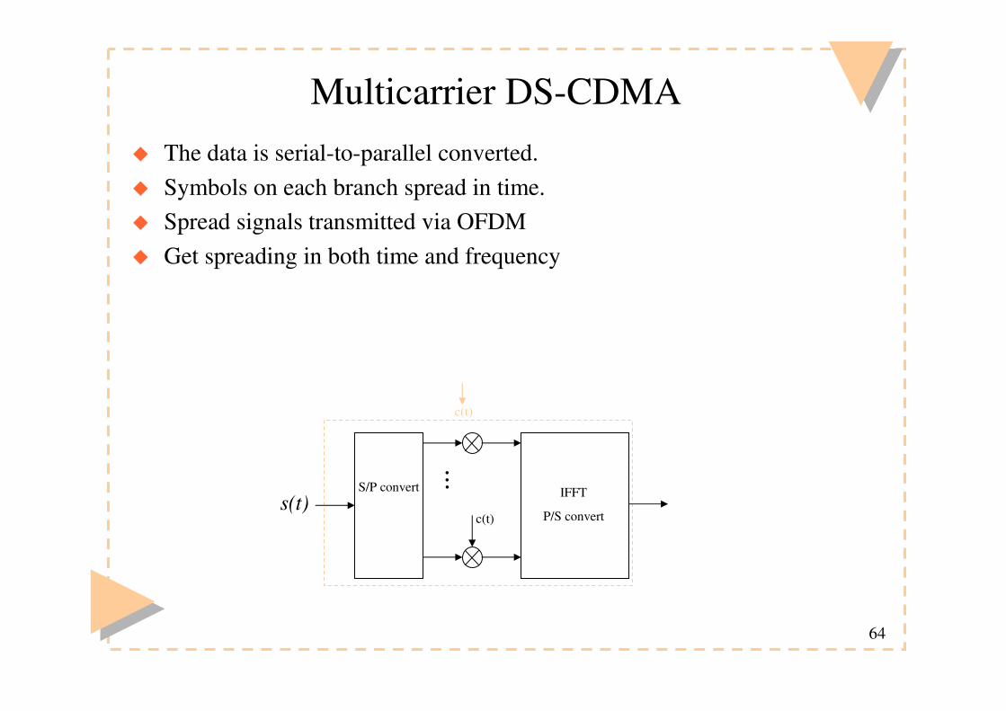
Multicarrier DS-CDMA� The data is serial-to-parallel converted.� Symbols on each branch spread in time.� Spread signals transmitted via OFDM� Get spreading in both time and frequency
c(t)
IFFT
P/S convert
.. .S/P converts(t)
c(t)

65

66
67
68

69

70
2.1 Single-Carrier Direct-Sequence CDMA
�Transmitted signal (BPSK modulated):
�Spreading code in the time-domain.
�Processing gain is ratio of bit to chip duration.
�Number of users N dependents upon cross-correlation of
codes.
�In frequency-selective fading channels, autocorrelation
properties also limit number of users.
(((( )))) [[[[ ]]]] [[[[ ]]]] (((( )))) (((( ))))���� ����−−−−====
−−−−
====−−−−−−−−====
M
Mi
N
jccbTDS tfjTiTtpjcibPts
c
1
01 2cos2
1ππππ

71
2.2 SC DS-CDMA Illustration
72
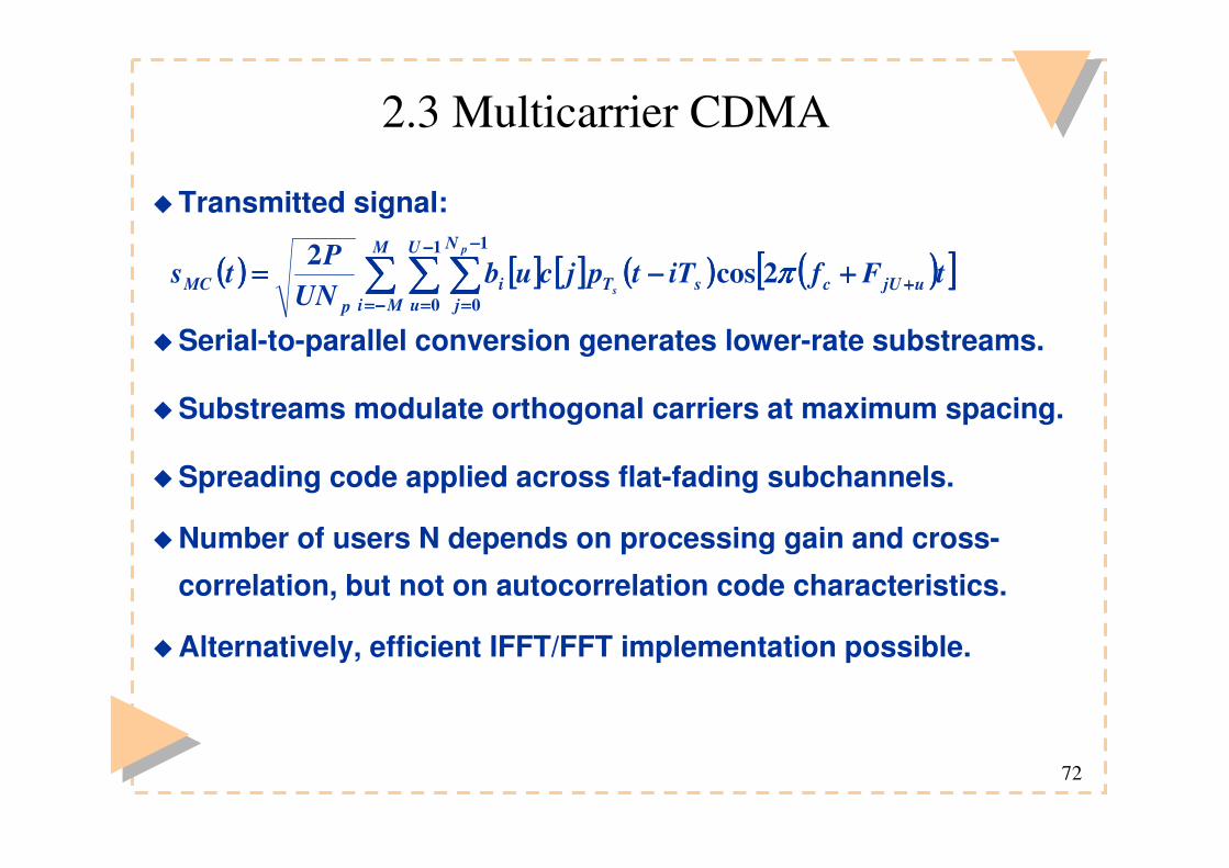
2.3 Multicarrier CDMA
�Transmitted signal:
�Serial-to-parallel conversion generates lower-rate substreams.
�Substreams modulate orthogonal carriers at maximum spacing.
�Spreading code applied across flat-fading subchannels.
�Number of users N depends on processing gain and cross-
correlation, but not on autocorrelation code characteristics.
�Alternatively, efficient IFFT/FFT implementation possible.
(((( )))) [[[[ ]]]] [[[[ ]]]] (((( )))) (((( ))))[[[[ ]]]]���� ���� ����−−−−====
−−−−
====
−−−−
====++++++++−−−−====
M
Mi
U
u
N
jujUcsTi
pMC
p
stFfiTtpjcub
UNPts
1
0
1
02cos2 ππππ

73
2.4 MC-CDMA Illustration

74
2.5 Multicarrier Direct-Sequence CDMA
�Transmitted signal:
�Hybrid scheme: joint spreading across time and frequency.
�Subcarriers not necessarily orthogonal.
�Processing gain usually product of T- and F-spreading codes.
�Number of users N depends on T- and F-domain spreading factors, cross-correlation, and autocorrelation code properties.
�Conventional MC DS-CDMA: only F-domain repetition.
�Unified family of generalized MC DS-CDMA schemes:
SC DS-CDMA and MC-CDMA represent the marginals.
(((( )))) [[[[ ]]]] [[[[ ]]]] (((( )))) [[[[ ]]]] (((( ))))[[[[ ]]]]���� �������� ����−−−−====
−−−−
====
−−−−
====
−−−−
====++++++++−−−−−−−−====
M
Mi
U
u
S
s
N
jusUcfcsTtiMC
p
ctFfscjTiTtpjcub
USPts
1
0
1
0
1
02cos2 ππππ

75
2.6 MC DS-CDMA Illustration

76
2.7 Flexibility Comparison
�Flexibility (degrees of freedom) of multiple access scheme
impact performance in diverse communication environments.
�Utilize during design phase or reconfiguration during operation.
�Assumptions: fixed system bandwidth, same chip waveform
and BPSK modulation, common bit rate.
�NOT fixed: bit-error-rate, processing gain or number of users.
�SC DS-CDMA:
� no degrees of freedom; system fully specified.

77
2.8 Flexibility Comparison Continued
�MC-CDMA
� Number of parallel bit streams (symbol bit depth U).
�Determines symbol duration and number of subcarriers.
�MC DS-CDMA
� Chip duration influences number of subcarriers.
� Number of parallel bit streams U determines F-code length.
� Spacing between adjacent subcarriers: 1/Ts to 2/Tc.
�Chosen to optimize BER or transmitted signal’s spectrum.
� Parameters allow for trade-offs between spectral efficiency,
BER, number of users, and degree of T- and/or F-domain
spreading.

78
3.1 Example: Ubiquitous Communication
�Broadband system:
� 20 MHz bandwidth to support range of services/rates.
� Support bit rate of 1 Mbps per user.
� Maximum number of users not specified.
�Channel properties:
� Delay spread between 0.1 and 3 µµµµs.
�Time-varying frequency-selective fading (ISI) channel.
� Different Doppler shift for lowest and highest frequencies.
79
3.2 Deficiencies of SC DS-CDMA
�Severe ISI for delay spread greater 1 µµµµs.
�Remedy: exploit frequency diversity using RAKE receiver.
� But optimal number of fingers depends on delay spread.
� Complex solution: adaptive MRC scheme.
� ISI destroys orthogonality of spreading codes.
�Remedy: Multiuser detection.
� But complexity increases at least linear with number of users.
� Requires signal processing at chip rate.

80
3.3 Deficiencies of MC-CDMA
�Remove ISI by choosing many subchannels.
� Problem: increased peak-to-average power ratio.
� Problem: varying correlation between adjacent subcarriers.
�Diversity order changes with coherence bandwidth.
�Different subchannel gains destroy orthogonality in F-domain.
�Remedy: Multiuser Detection (MUD).
� But complexity increases at least linear with number of users.
�Remedy: Zero-Forcing Equalizer could restore orthogonality.
� Suffers from noise enhancement.

81
4.1 MC DS-CDMA System Design
�Use system parameters to adjust to propagation environment.
�Goes beyond trade-off between SC DS-CDMA and MC-CDMA.
�System design for diverse channels:
1 Choose chip duration > highest delay spread.
� Ensures flat-fading subcarriers.
2 Select associated subcarrier spacing > coherence bandwidth.
� Enables maximum frequency diversity order.
�Result: system that avoids or mitigates problems encountered
in SC DS-CDMA and MC-CDMA over wide range of delay
spreads.
82
4.2 Advantages & Disadvantages
�Advantages:
� Independent fading on diversity-combined subcarriers.
� Lower peak-to-average power ratio.
� T-domain spreading codes remain orthogonal.
� Downlink at near single-user performance without MUD.
� Frequency diversity order remains a constant value.
�Disadvantages:
� Difference in Doppler shift destroys subcarrier orthogonality.
� Assertion: negligible at moderate traveling speeds.
� Diversity order may be insufficient for BER target.
� Countermeasure: increase via transmit diversity.

83

84
�MU-MC-CDMA�RAKE RX�OVSF DCA-SCHEDULING�NOVSF
Top Related