Cross-border Interference Issues in CDMA Networks … · · 2017-02-13Cross-border Interference...
39
Executive Seminar on 3G CDMA Technologies Dubai, UAE 25-26, July 2005 1 Executive Seminar on 3G CDMA Technologies Dubai, UAE July 25 - 26, 2005 Cross Cross - - border Interference Issues border Interference Issues in CDMA Networks in CDMA Networks Mullaguru Naidu Engineering Services Group [email protected]
Transcript of Cross-border Interference Issues in CDMA Networks … · · 2017-02-13Cross-border Interference...
Executive Seminar on 3G CDMA TechnologiesDubai, UAE 25-26, July 2005
1
Executive Seminar on 3G CDMA TechnologiesDubai, UAE July 25 - 26, 2005
CrossCross--border Interference Issuesborder Interference Issuesin CDMA Networksin CDMA Networks
Mullaguru NaiduEngineering Services Group
Executive Seminar on 3G CDMA TechnologiesDubai, UAE 25-26, July 2005
2
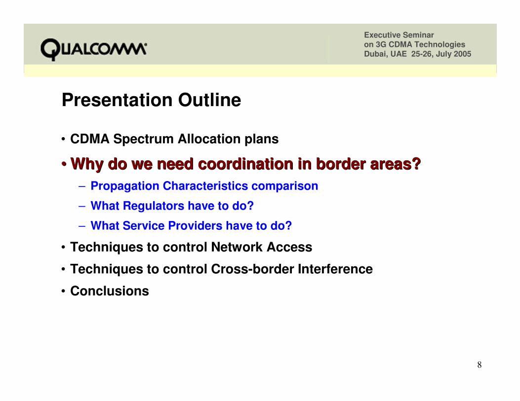
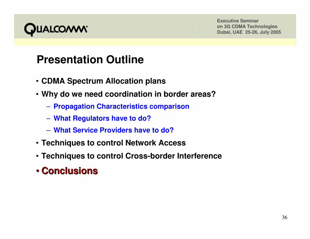
Presentation OutlinePresentation Outline
•• CDMA Spectrum Allocation plansCDMA Spectrum Allocation plans• Why do we need coordination in border areas?
– Propagation Characteristics comparison
– What Regulators have to do?
– What Service Providers have to do?
• Techniques to control Network Access
• Techniques to control Cross-border Interference
• Conclusions
Executive Seminar on 3G CDMA TechnologiesDubai, UAE 25-26, July 2005
3
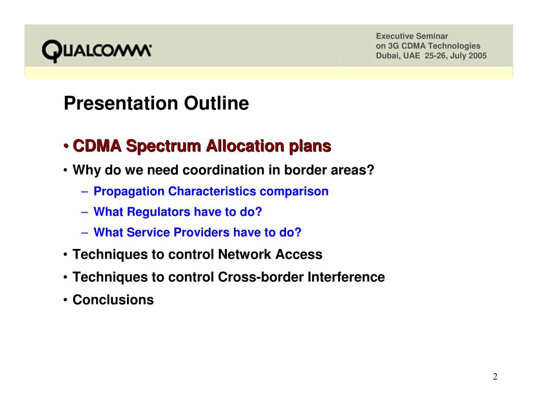
824 MHz 849 869 894 850 MHz US Cellular Band(25 + 25 MHz Spectrum)
45 MHz Separation
1850 MHz 1910 1930 19901900 MHz US PCS Band(60 + 60 MHz Spectrum)
80 MHz Separation
Commonly used Spectrum bands in CDMA
452.5 MHz 457.475 462.5 467.475 450 MHz NMT ‘A’ Band
(4.975 + 4.975 MHz Spectrum)10 MHz Separation
Uplink Downlink
Executive Seminar on 3G CDMA TechnologiesDubai, UAE 25-26, July 2005
4
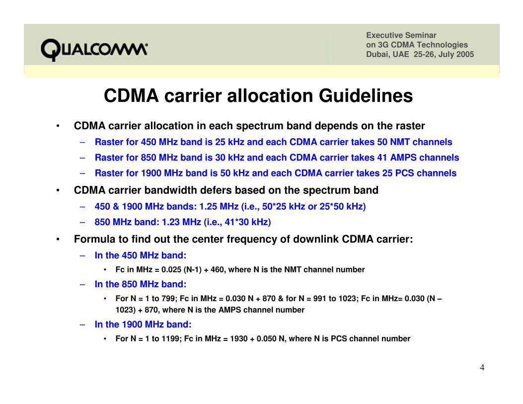
CDMA carrier allocation GuidelinesCDMA carrier allocation Guidelines• CDMA carrier allocation in each spectrum band depends on the raster
– Raster for 450 MHz band is 25 kHz and each CDMA carrier takes 50 NMT channels
– Raster for 850 MHz band is 30 kHz and each CDMA carrier takes 41 AMPS channels
– Raster for 1900 MHz band is 50 kHz and each CDMA carrier takes 25 PCS channels
• CDMA carrier bandwidth defers based on the spectrum band– 450 & 1900 MHz bands: 1.25 MHz (i.e., 50*25 kHz or 25*50 kHz)
– 850 MHz band: 1.23 MHz (i.e., 41*30 kHz)
• Formula to find out the center frequency of downlink CDMA carrier:– In the 450 MHz band:
• Fc in MHz = 0.025 (N-1) + 460, where N is the NMT channel number
– In the 850 MHz band:• For N = 1 to 799; Fc in MHz = 0.030 N + 870 & for N = 991 to 1023; Fc in MHz= 0.030 (N −−−−
1023) + 870, where N is the AMPS channel number
– In the 1900 MHz band:• For N = 1 to 1199; Fc in MHz = 1930 + 0.050 N, where N is PCS channel number
Executive Seminar on 3G CDMA TechnologiesDubai, UAE 25-26, July 2005
5
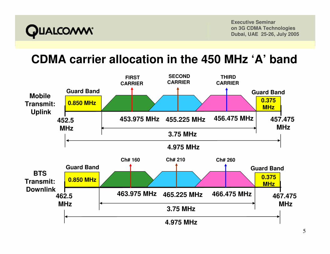
CDMA carrier allocation in the 450 MHz CDMA carrier allocation in the 450 MHz ‘‘AA’’ band band SECONDCARRIER
THIRDCARRIER
Guard Band Guard Band
3.75 MHz
453.975 MHz 456.475 MHz
FIRSTCARRIER
4.975 MHz
455.225 MHz452.5 MHz
462.5 MHz
457.475 MHz
467.475 MHz
BTSTransmit:Downlink
MobileTransmit:
Uplink
Guard Band Guard Band
3.75 MHz
463.975 MHz 466.475 MHz
0.850 MHz 0.375 MHz
4.975 MHz
465.225 MHz
Ch# 160 Ch# 260 Ch# 210
0.850 MHz 0.375 MHz
Executive Seminar on 3G CDMA TechnologiesDubai, UAE 25-26, July 2005
6
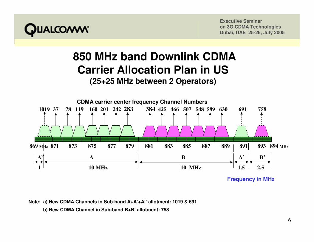
850 MHz band Downlink CDMA Carrier Allocation Plan in US
(25+25 MHz between 2 Operators)
Note: a) New CDMA Channels in Sub-band A+A’+A’’ allotment: 1019 & 691
b) New CDMA Channel in Sub-band B+B’ allotment: 758
869 MHz 871 873 875 877 879 881 883 885 887 889 891 893 894 MHz
Frequency in MHz
A” A B A’ B’
1 10 MHz 10 MHz 1.5 2.5
CDMA carrier center frequency Channel Numbers1019 37 78 119 160 201 242 283 384 425 466 507 548 589 630 691 758
Executive Seminar on 3G CDMA TechnologiesDubai, UAE 25-26, July 2005
7
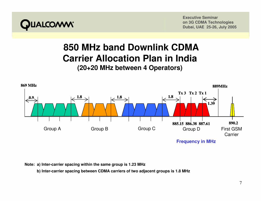
885.15 886.38 887.61
869 MHz 889MHz
1.80.9 1.8 1.8Tx 3 Tx 2 Tx 1
1.39
890.2 885.15 886.38 887.61
869 MHz 889MHz
1.81.80.9 1.81.8 1.81.8Tx 3 Tx 2 Tx 1
1.39
890.2 Group A Group B Group C Group D First GSM
Carrier
850 MHz band Downlink CDMA Carrier Allocation Plan in India
(20+20 MHz between 4 Operators)
Frequency in MHz
Note: a) Inter-carrier spacing within the same group is 1.23 MHz
b) Inter-carrier spacing between CDMA carriers of two adjacent groups is 1.8 MHz
Executive Seminar on 3G CDMA TechnologiesDubai, UAE 25-26, July 2005
8
Presentation OutlinePresentation Outline
• CDMA Spectrum Allocation plans
•• Why do we need coordination in border areas?Why do we need coordination in border areas?– Propagation Characteristics comparison
– What Regulators have to do?
– What Service Providers have to do?
• Techniques to control Network Access
• Techniques to control Cross-border Interference
• Conclusions
Executive Seminar on 3G CDMA TechnologiesDubai, UAE 25-26, July 2005
9
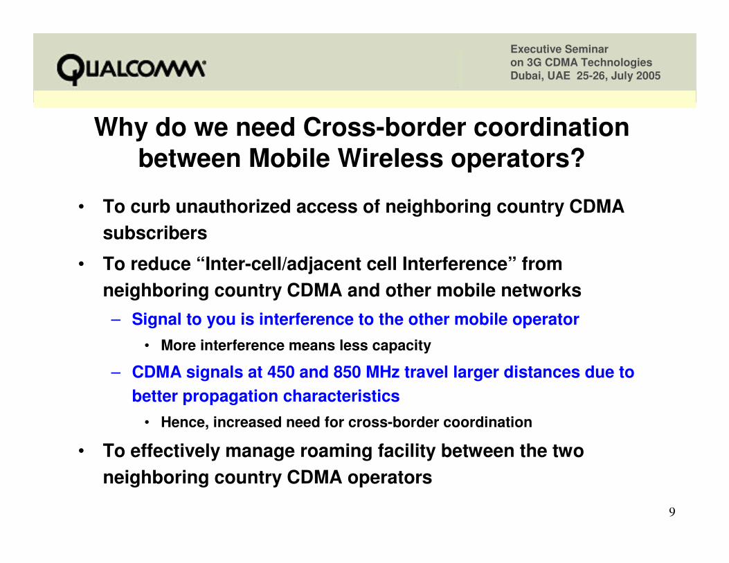
Why do we need CrossWhy do we need Cross--border coordination border coordination between Mobile Wireless operators?between Mobile Wireless operators?
• To curb unauthorized access of neighboring country CDMA subscribers
• To reduce “Inter-cell/adjacent cell Interference” from neighboring country CDMA and other mobile networks– Signal to you is interference to the other mobile operator
• More interference means less capacity
– CDMA signals at 450 and 850 MHz travel larger distances due to better propagation characteristics
• Hence, increased need for cross-border coordination
• To effectively manage roaming facility between the two neighboring country CDMA operators
Executive Seminar on 3G CDMA TechnologiesDubai, UAE 25-26, July 2005
10
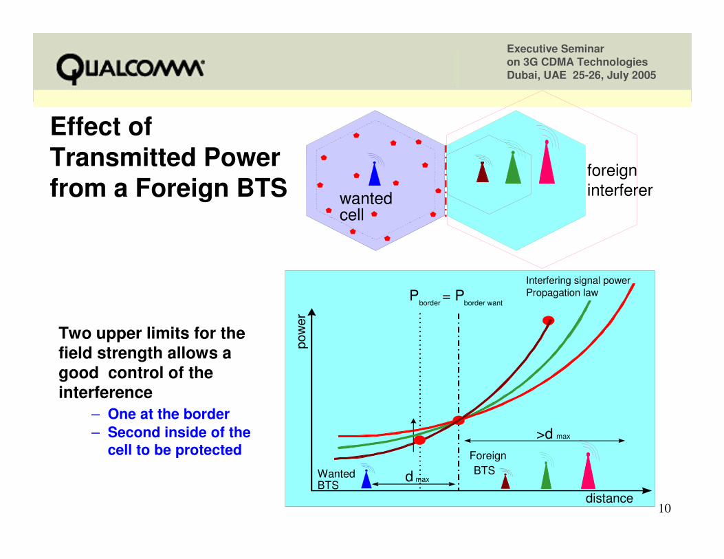
Effect of Effect of Transmitted Power Transmitted Power from a Foreign BTSfrom a Foreign BTS
Interfering signal power Propagation law
pow
er
distance
ForeignBTSWanted
BTS
P = Pborder border want
d max
>d max
wantedcell
foreigninterferer
Two upper limits for the field strength allows a good control of the interference
– One at the border– Second inside of the
cell to be protected
Executive Seminar on 3G CDMA TechnologiesDubai, UAE 25-26, July 2005
11
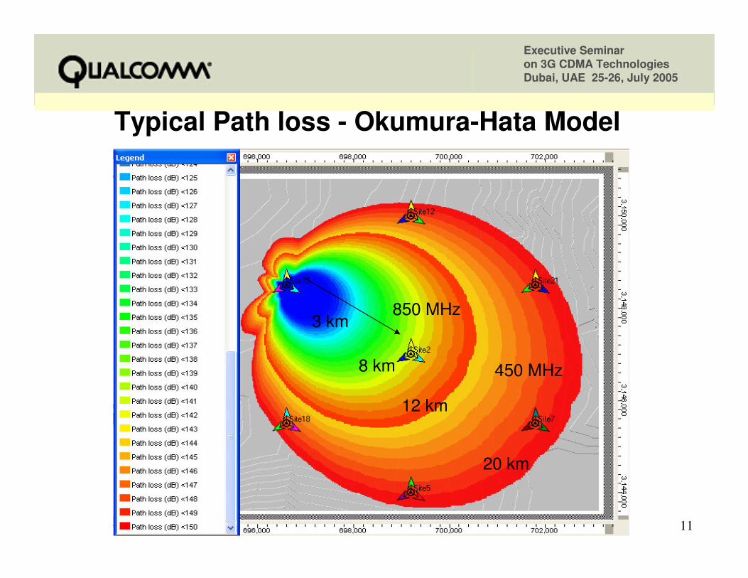
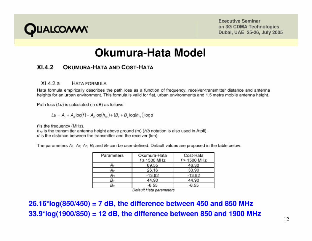
Typical Path loss Typical Path loss -- OkumuraOkumura--Hata ModelHata Model
Stationary
450 MHz
850 MHz3 km
8 km
20 km
12 km
Executive Seminar on 3G CDMA TechnologiesDubai, UAE 25-26, July 2005
12
OkumuraOkumura--Hata ModelHata Model
26.16*log(850/450) = 7 dB, the difference between 450 and 850 MHz 33.9*log(1900/850) = 12 dB, the difference between 850 and 1900 MHz
Executive Seminar on 3G CDMA TechnologiesDubai, UAE 25-26, July 2005
13
What Telecom Regulators have to do?What Telecom Regulators have to do?• Under spectrum management guidelines, Regulators have to see that
different users and different uses of radio frequency should not interfere with each other
• Regulators have to tackle “negative externality” problems such as – Use of faulty or non-standard equipment – Unauthorized or illegal use of frequencies– Spillover signal effects from neighboring jurisdictions– Use of inappropriate levels of power– Finding the optimum location of antennae
• Achieving this kind of “technical efficiency” is the job of engineers within the purview of the regulatory body
• Another much wider function of the Regulators is to achieve “economic efficiency”
– Involves judgment regarding the allocation of relatively scarce spectrum among alternative users to provide competing services
– Markets will change over time and so will the price consumers are willing to pay for different categories of services, hence need for re-look over the times
Executive Seminar on 3G CDMA TechnologiesDubai, UAE 25-26, July 2005
14
Model CrossModel Cross--border Agreement on Monitoringborder Agreement on Monitoring• An agreement between the Regulators is required:
– To reduce the response time and to offer mutual help in cases ofInterference and other related tasks
– To perform monitoring measurements by vehicle, using their own apparatus on the other side of the common border
• With this, either regulator can directly ask the other Regulator to carry out fixed or mobile monitoring measurements in case of interference and /or frequency co-ordination
• This direct co-operation also ceases when the distance from the border exceeds 72 kms
• Copy of the cross-border agreement on radio monitoring shall be kept in the measuring vehicle
• Monitored measurements (time, place, route, equipment used and values measured) to be reported to all
Executive Seminar on 3G CDMA TechnologiesDubai, UAE 25-26, July 2005
15
Why Coordination required between Operators ?Why Coordination required between Operators ?
• To exchange border area BTSs’ information
• To follow standard guidelines for the preferential CDMA carrier frequency selection (as a Primary channel) in border areas
• To properly plan for the PN offsets in border areas– Separate allotment guidelines for bilateral and trilateral cases
• To assist Regulators in monitoring and measurements job
• To carryout correction measures in order to reduce / mitigate interference effects to other operators’ network in the border areas
Executive Seminar on 3G CDMA TechnologiesDubai, UAE 25-26, July 2005
16
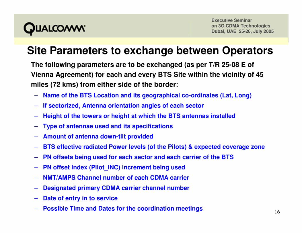
Site Parameters to exchange between OperatorsSite Parameters to exchange between OperatorsThe following parameters are to be exchanged (as per T/R 25-08 E of Vienna Agreement) for each and every BTS Site within the vicinity of 45 miles (72 kms) from either side of the border:
– Name of the BTS Location and its geographical co-ordinates (Lat, Long)
– If sectorized, Antenna orientation angles of each sector
– Height of the towers or height at which the BTS antennas installed
– Type of antennae used and its specifications
– Amount of antenna down-tilt provided
– BTS effective radiated Power levels (of the Pilots) & expected coverage zone
– PN offsets being used for each sector and each carrier of the BTS
– PN offset index (Pilot_INC) increment being used
– NMT/AMPS Channel number of each CDMA carrier
– Designated primary CDMA carrier channel number
– Date of entry in to service
– Possible Time and Dates for the coordination meetings
Executive Seminar on 3G CDMA TechnologiesDubai, UAE 25-26, July 2005
17
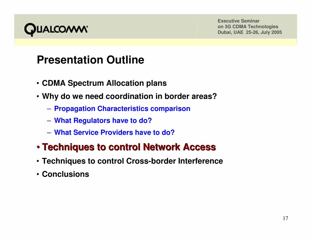
Presentation OutlinePresentation Outline
• CDMA Spectrum Allocation plans
• Why do we need coordination in border areas?– Propagation Characteristics comparison
– What Regulators have to do?
– What Service Providers have to do?
•• Techniques to control Network AccessTechniques to control Network Access• Techniques to control Cross-border Interference
• Conclusions
Executive Seminar on 3G CDMA TechnologiesDubai, UAE 25-26, July 2005
18
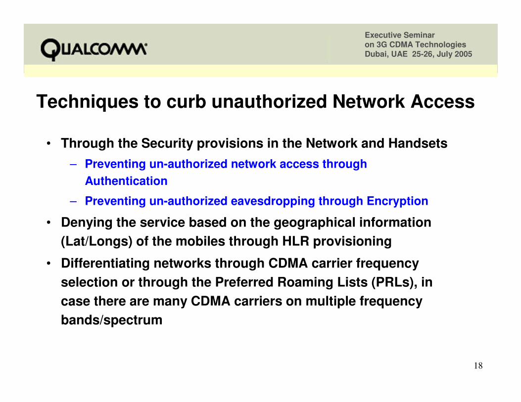
Techniques to curb unauthorized Network AccessTechniques to curb unauthorized Network Access
• Through the Security provisions in the Network and Handsets– Preventing un-authorized network access through
Authentication
– Preventing un-authorized eavesdropping through Encryption
• Denying the service based on the geographical information (Lat/Longs) of the mobiles through HLR provisioning
• Differentiating networks through CDMA carrier frequency selection or through the Preferred Roaming Lists (PRLs), in case there are many CDMA carriers on multiple frequency bands/spectrum
Executive Seminar on 3G CDMA TechnologiesDubai, UAE 25-26, July 2005
19
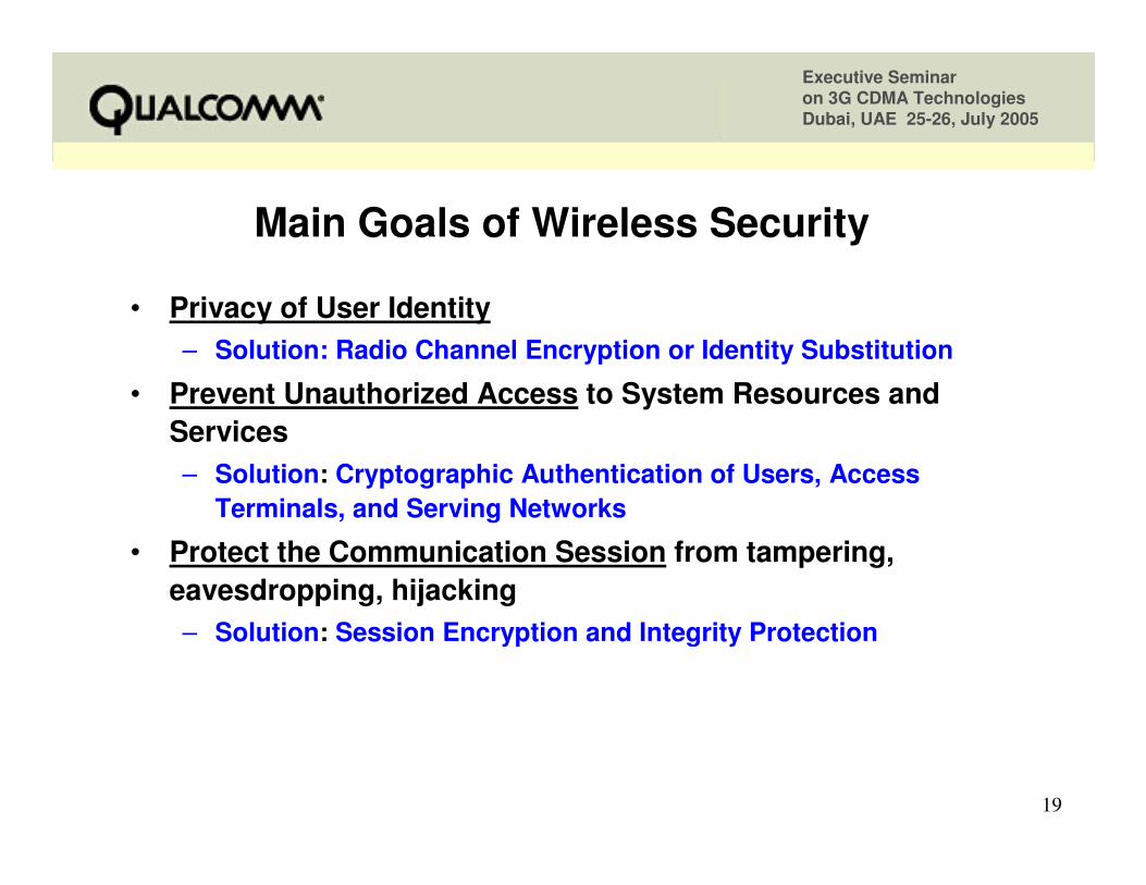
Main Goals of Wireless SecurityMain Goals of Wireless Security
• Privacy of User Identity– Solution: Radio Channel Encryption or Identity Substitution
• Prevent Unauthorized Access to System Resources and Services– Solution: Cryptographic Authentication of Users, Access
Terminals, and Serving Networks
• Protect the Communication Session from tampering, eavesdropping, hijacking– Solution: Session Encryption and Integrity Protection
Executive Seminar on 3G CDMA TechnologiesDubai, UAE 25-26, July 2005
20
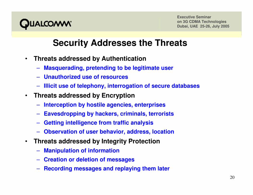
Security Addresses the ThreatsSecurity Addresses the Threats
• Threats addressed by Authentication– Masquerading, pretending to be legitimate user– Unauthorized use of resources– Illicit use of telephony, interrogation of secure databases
• Threats addressed by Encryption– Interception by hostile agencies, enterprises– Eavesdropping by hackers, criminals, terrorists – Getting intelligence from traffic analysis– Observation of user behavior, address, location
• Threats addressed by Integrity Protection– Manipulation of information– Creation or deletion of messages– Recording messages and replaying them later
Executive Seminar on 3G CDMA TechnologiesDubai, UAE 25-26, July 2005
21
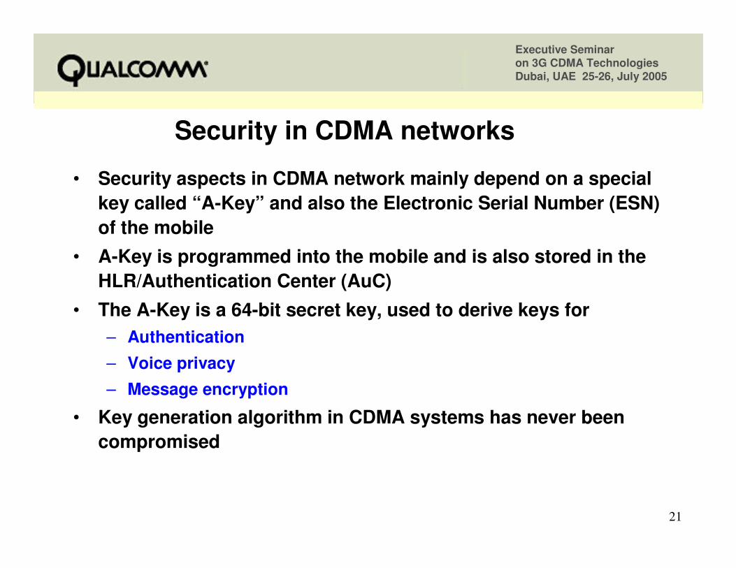
Security in CDMA networksSecurity in CDMA networks
• Security aspects in CDMA network mainly depend on a special key called “A-Key” and also the Electronic Serial Number (ESN) of the mobile
• A-Key is programmed into the mobile and is also stored in the HLR/Authentication Center (AuC)
• The A-Key is a 64-bit secret key, used to derive keys for – Authentication – Voice privacy – Message encryption
• Key generation algorithm in CDMA systems has never been compromised
Executive Seminar on 3G CDMA TechnologiesDubai, UAE 25-26, July 2005
22
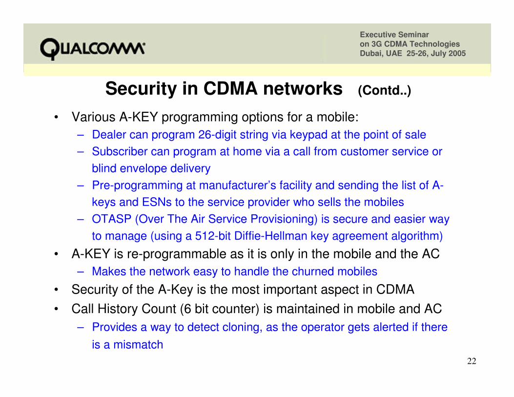
Security in CDMA networks Security in CDMA networks (Contd..)(Contd..)
• Various A-KEY programming options for a mobile:– Dealer can program 26-digit string via keypad at the point of sale – Subscriber can program at home via a call from customer service or
blind envelope delivery – Pre-programming at manufacturer’s facility and sending the list of A-
keys and ESNs to the service provider who sells the mobiles– OTASP (Over The Air Service Provisioning) is secure and easier way
to manage (using a 512-bit Diffie-Hellman key agreement algorithm)
• A-KEY is re-programmable as it is only in the mobile and the AC – Makes the network easy to handle the churned mobiles
• Security of the A-Key is the most important aspect in CDMA• Call History Count (6 bit counter) is maintained in mobile and AC
– Provides a way to detect cloning, as the operator gets alerted if there is a mismatch
Executive Seminar on 3G CDMA TechnologiesDubai, UAE 25-26, July 2005
23
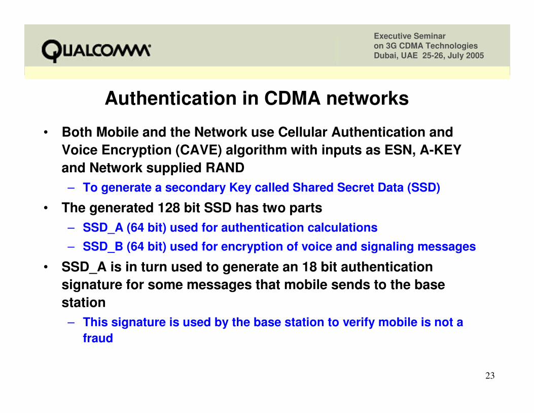
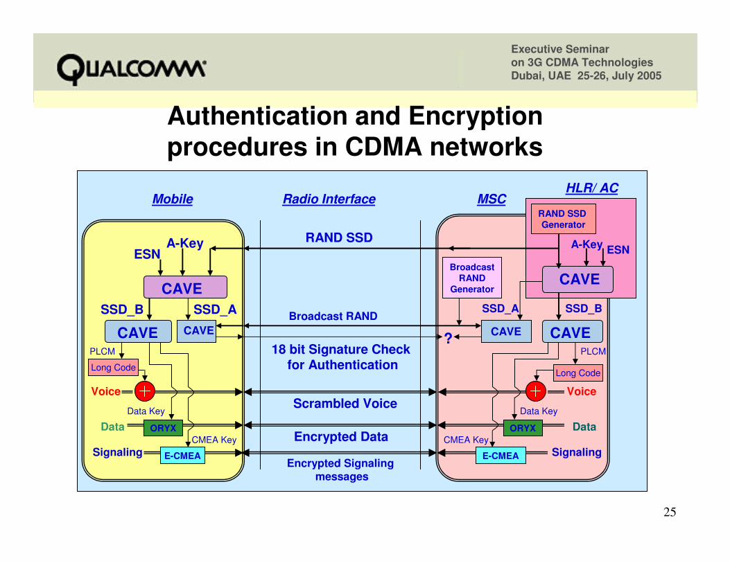
Authentication in CDMA networksAuthentication in CDMA networks
• Both Mobile and the Network use Cellular Authentication and Voice Encryption (CAVE) algorithm with inputs as ESN, A-KEY and Network supplied RAND– To generate a secondary Key called Shared Secret Data (SSD)
• The generated 128 bit SSD has two parts– SSD_A (64 bit) used for authentication calculations– SSD_B (64 bit) used for encryption of voice and signaling messages
• SSD_A is in turn used to generate an 18 bit authentication signature for some messages that mobile sends to the base station – This signature is used by the base station to verify mobile is not a
fraud
Executive Seminar on 3G CDMA TechnologiesDubai, UAE 25-26, July 2005
24
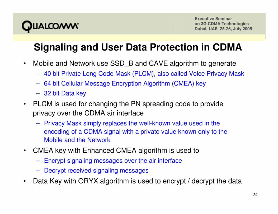
Signaling and User Data Protection in CDMASignaling and User Data Protection in CDMA• Mobile and Network use SSD_B and CAVE algorithm to generate
– 40 bit Private Long Code Mask (PLCM), also called Voice Privacy Mask
– 64 bit Cellular Message Encryption Algorithm (CMEA) key
– 32 bit Data key
• PLCM is used for changing the PN spreading code to provide privacy over the CDMA air interface – Privacy Mask simply replaces the well-known value used in the
encoding of a CDMA signal with a private value known only to theMobile and the Network
• CMEA key with Enhanced CMEA algorithm is used to– Encrypt signaling messages over the air interface
– Decrypt received signaling messages
• Data Key with ORYX algorithm is used to encrypt / decrypt the data
Executive Seminar on 3G CDMA TechnologiesDubai, UAE 25-26, July 2005
25
Authentication and Encryption Authentication and Encryption procedures in CDMA networksprocedures in CDMA networks
A-KeyESN
18 bit Signature Check for Authentication
RAND SSD
Mobile Radio Interface MSC
CAVESSD_B SSD_B
Encrypted DataData Data
CAVE?
SSD_A SSD_A
CAVECAVE CAVE
Data KeyData Key
E-CMEAEncrypted Signaling
messages
E-CMEA Signaling
PLCM
Signaling
PLCM
CMEA Key CMEA Key
A-Key ESN
CAVE
RAND SSD Generator
HLR/ AC
Broadcast RAND
Broadcast RAND
Generator
Scrambled VoiceVoice Voice
ORYX
Long Code
ORYX
Long Code
Executive Seminar on 3G CDMA TechnologiesDubai, UAE 25-26, July 2005
26
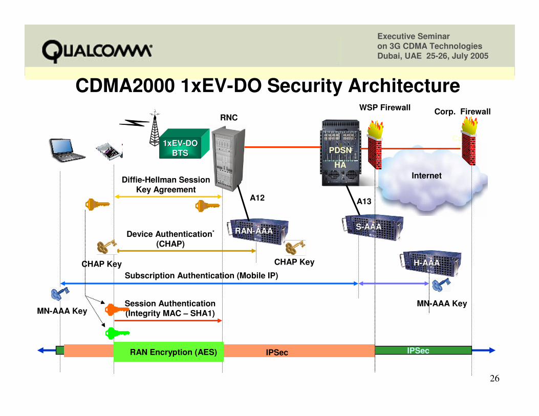
CDMA2000 1xEVCDMA2000 1xEV--DO Security ArchitectureDO Security Architecture
RANRAN--AAAAAA SS--AAAAAA
RNC
PDSN
HA
Corp. FW
Internet
1xEV1xEV--DODOBTSBTS
A12 A13
Device Authentication*
(CHAP)
Subscription Authentication (Mobile IP)
Session Authentication (Integrity MAC – SHA1)
IPSecRAN Encryption (AES)
Diffie-Hellman Session Key Agreement
WSP Firewall Corp. Firewall
IPSec
HH--AAAAAA
MN-AAA KeyMN-AAA Key
CHAP KeyCHAP Key
Executive Seminar on 3G CDMA TechnologiesDubai, UAE 25-26, July 2005
27
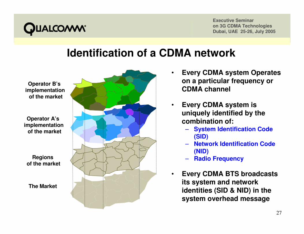
• Every CDMA system Operates on a particular frequency or CDMA channel
• Every CDMA system is uniquely identified by the combination of:
– System Identification Code (SID)
– Network Identification Code (NID)
– Radio Frequency
• Every CDMA BTS broadcasts its system and network identities (SID & NID) in the system overhead message
The Market
Regionsof the market
Operator A’s implementation
of the market
Operator B’s implementation
of the market
Identification of a CDMA networkIdentification of a CDMA network
Executive Seminar on 3G CDMA TechnologiesDubai, UAE 25-26, July 2005
28
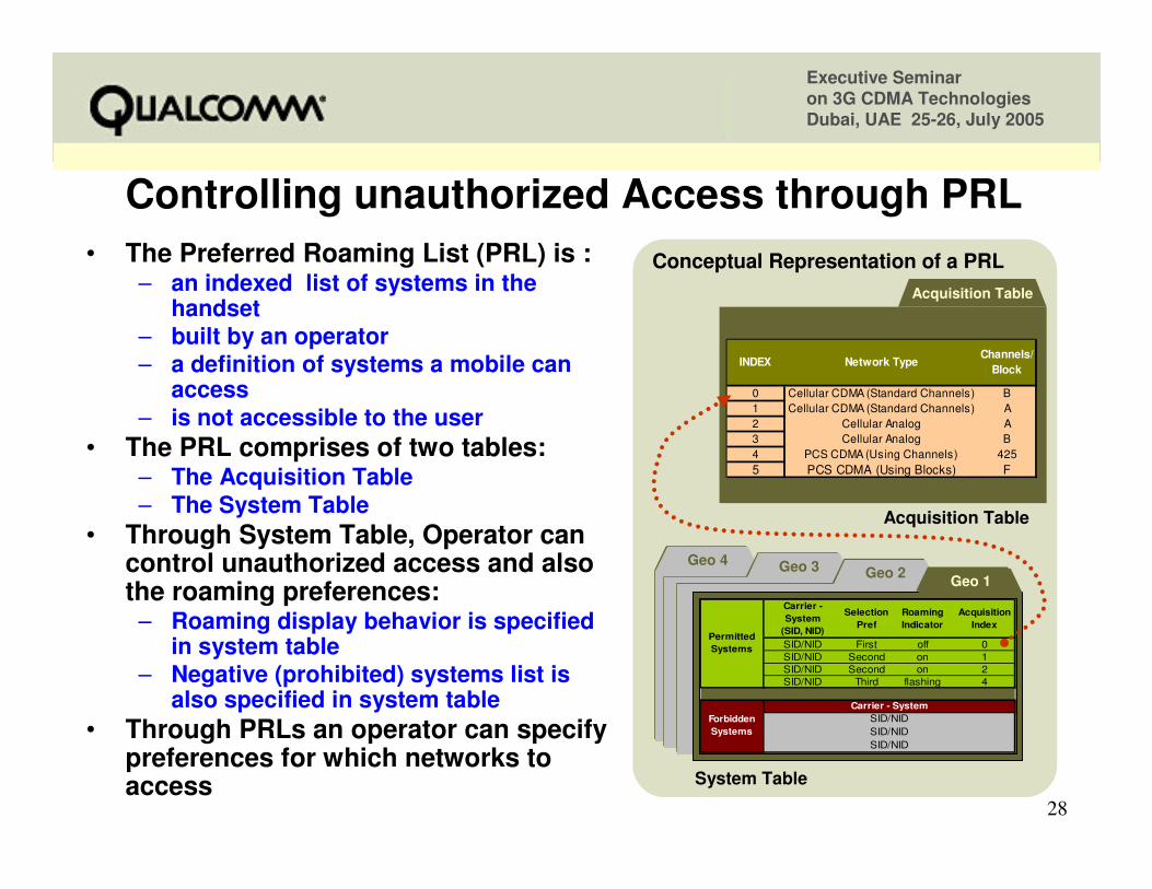
• The Preferred Roaming List (PRL) is :– an indexed list of systems in the
handset– built by an operator – a definition of systems a mobile can
access– is not accessible to the user
• The PRL comprises of two tables:– The Acquisition Table– The System Table
• Through System Table, Operator can control unauthorized access and also the roaming preferences:
– Roaming display behavior is specified in system table
– Negative (prohibited) systems list is also specified in system table
• Through PRLs an operator can specify preferences for which networks to access
Conceptual Representation of a PRL
Geo 4Geo 4 Geo 3Geo 3 Geo 2Geo 2
Carrier - System
(SID, NID)
Selection Pref
Roaming Indicator
Acquisition Index
SID/NID First off 0SID/NID Second on 1SID/NID Second on 2SID/NID Third flashing 4
Permitted Systems
Carrier - SystemSID/NID
SID/NIDSID/NID
Forbidden Systems
Geo 1Geo 1
Acquisition Table
INDEX Network TypeChannels/
Block
0 Cellular CDMA (Standard Channels) B1 Cellular CDMA (Standard Channels) A2 Cellular Analog A3 Cellular Analog B4 PCS CDMA (Using Channels) 4255 PCS CDMA (Using Blocks) F
System Table
Acquisition Table
Controlling unauthorized Access through PRLControlling unauthorized Access through PRL
Executive Seminar on 3G CDMA TechnologiesDubai, UAE 25-26, July 2005
29
Presentation OutlinePresentation Outline
• CDMA Spectrum Allocation plans
• Why do we need coordination in border areas?– Propagation Characteristics comparison
– What Regulators have to do?
– What Service Providers have to do?
• Techniques to control Network Access
•• Techniques to control Techniques to control CrossCross--borderborder InterferenceInterference• Conclusions
Executive Seminar on 3G CDMA TechnologiesDubai, UAE 25-26, July 2005
30
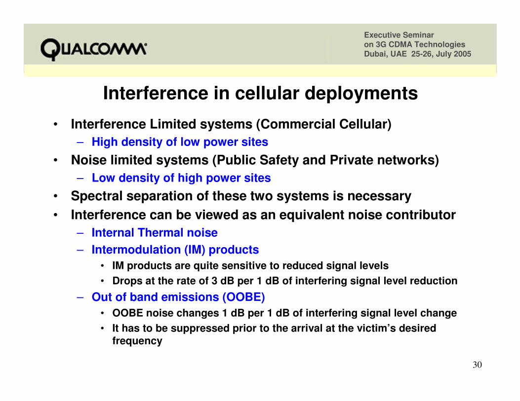
Interference in cellular deploymentsInterference in cellular deployments
• Interference Limited systems (Commercial Cellular)– High density of low power sites
• Noise limited systems (Public Safety and Private networks)– Low density of high power sites
• Spectral separation of these two systems is necessary• Interference can be viewed as an equivalent noise contributor
– Internal Thermal noise– Intermodulation (IM) products
• IM products are quite sensitive to reduced signal levels• Drops at the rate of 3 dB per 1 dB of interfering signal level reduction
– Out of band emissions (OOBE)• OOBE noise changes 1 dB per 1 dB of interfering signal level change• It has to be suppressed prior to the arrival at the victim’s desired
frequency
Executive Seminar on 3G CDMA TechnologiesDubai, UAE 25-26, July 2005
31
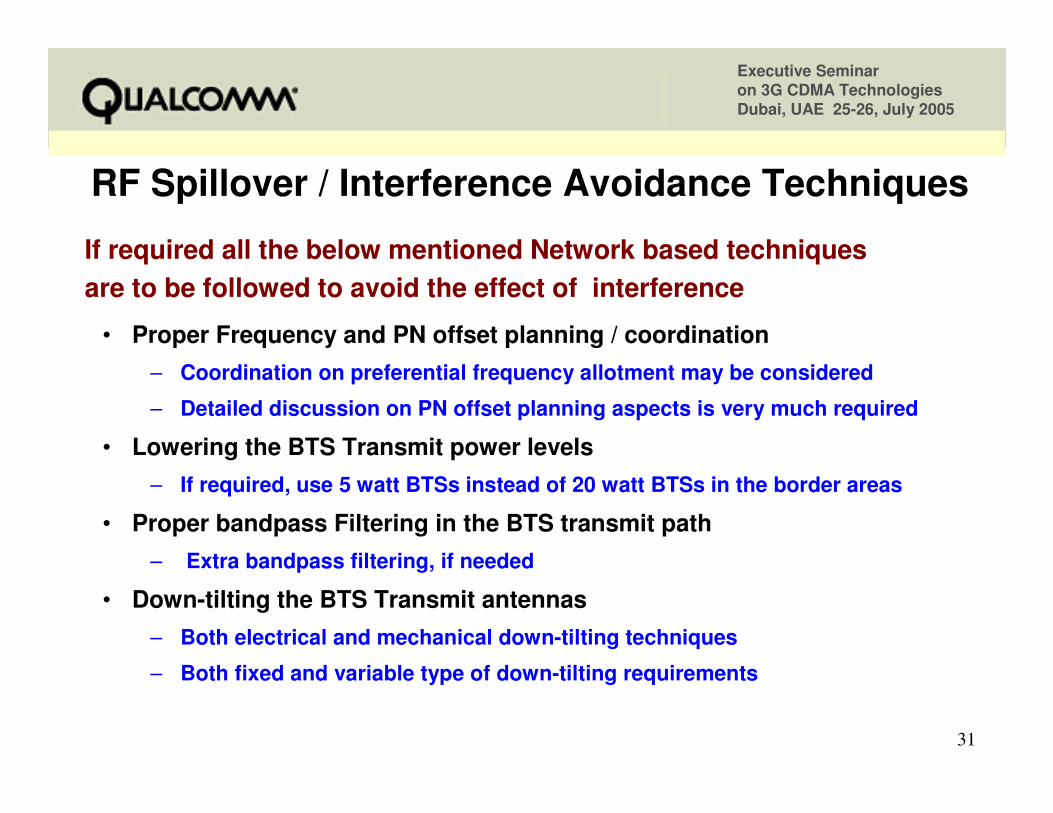
RF Spillover / Interference Avoidance TechniquesRF Spillover / Interference Avoidance Techniques
• Proper Frequency and PN offset planning / coordination– Coordination on preferential frequency allotment may be considered
– Detailed discussion on PN offset planning aspects is very much required
• Lowering the BTS Transmit power levels– If required, use 5 watt BTSs instead of 20 watt BTSs in the border areas
• Proper bandpass Filtering in the BTS transmit path– Extra bandpass filtering, if needed
• Down-tilting the BTS Transmit antennas– Both electrical and mechanical down-tilting techniques
– Both fixed and variable type of down-tilting requirements
If required all the below mentioned Network based techniques are to be followed to avoid the effect of interference
Executive Seminar on 3G CDMA TechnologiesDubai, UAE 25-26, July 2005
32
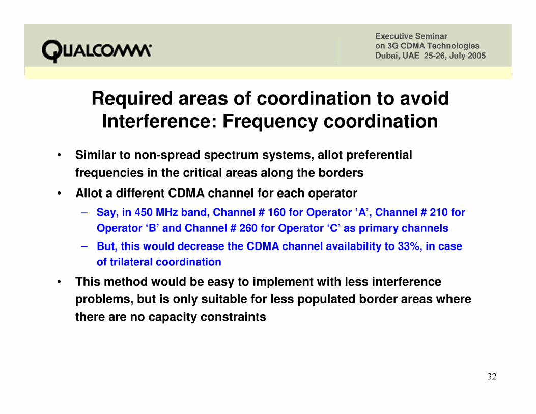
Required areas of coordination to avoid Required areas of coordination to avoid Interference: Interference: Frequency coordination
• Similar to non-spread spectrum systems, allot preferential frequencies in the critical areas along the borders
• Allot a different CDMA channel for each operator– Say, in 450 MHz band, Channel # 160 for Operator ‘A’, Channel # 210 for
Operator ‘B’ and Channel # 260 for Operator ‘C’ as primary channels
– But, this would decrease the CDMA channel availability to 33%, in case of trilateral coordination
• This method would be easy to implement with less interference problems, but is only suitable for less populated border areas where there are no capacity constraints
Executive Seminar on 3G CDMA TechnologiesDubai, UAE 25-26, July 2005
33
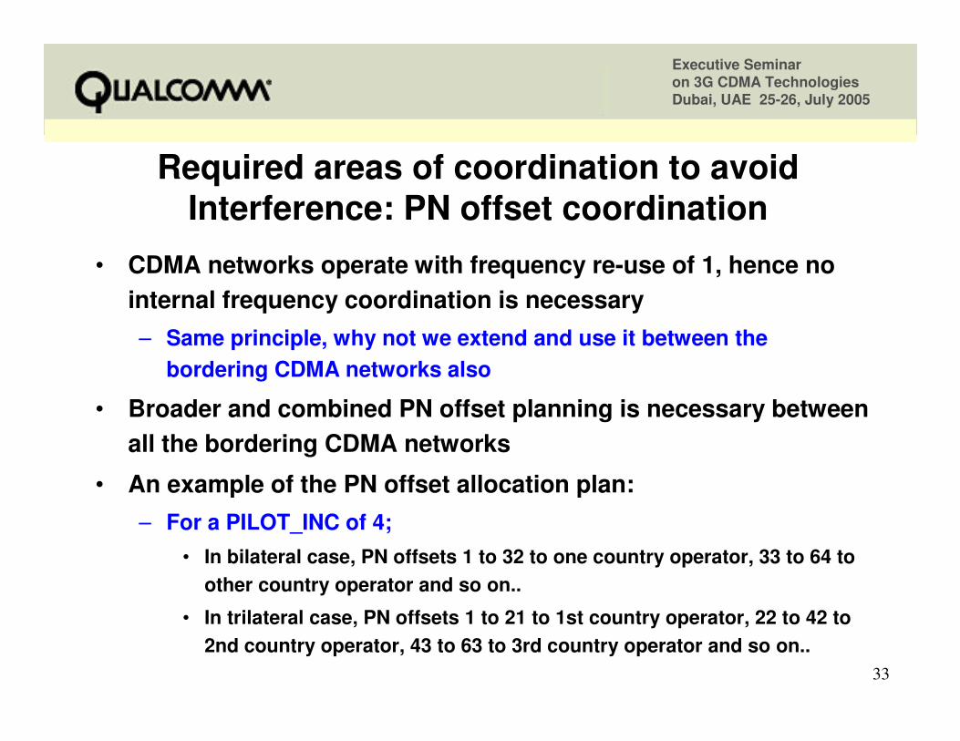
Required areas of coordination to avoid Required areas of coordination to avoid Interference: PN offset coordinationInterference: PN offset coordination
• CDMA networks operate with frequency re-use of 1, hence no internal frequency coordination is necessary– Same principle, why not we extend and use it between the
bordering CDMA networks also
• Broader and combined PN offset planning is necessary between all the bordering CDMA networks
• An example of the PN offset allocation plan:– For a PILOT_INC of 4;
• In bilateral case, PN offsets 1 to 32 to one country operator, 33 to 64 to other country operator and so on..
• In trilateral case, PN offsets 1 to 21 to 1st country operator, 22 to 42 to 2nd country operator, 43 to 63 to 3rd country operator and so on..
Executive Seminar on 3G CDMA TechnologiesDubai, UAE 25-26, July 2005
34
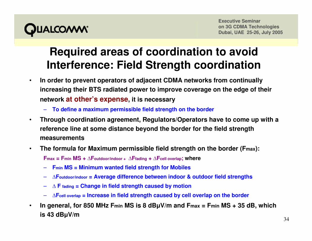
Required areas of coordination to avoid Interference: Field Strength coordination
• In order to prevent operators of adjacent CDMA networks from continually increasing their BTS radiated power to improve coverage on the edge of their
network at other’s expense, it is necessary– To define a maximum permissible field strength on the border
• Through coordination agreement, Regulators/Operators have to come up with a reference line at some distance beyond the border for the field strength measurements
• The formula for Maximum permissible field strength on the border (Fmax):Fmax = Fmin MS + �Foutdoor/indoor + �Ffading + �Fcell overlap; where
– Fmin MS = Minimum wanted field strength for Mobiles
– �Foutdoor/indoor = Average difference between indoor & outdoor field strengths
– � F fading = Change in field strength caused by motion
– �Fcell overlap = Increase in field strength caused by cell overlap on the border
• In general, for 850 MHz Fmin MS is 8 dB�V/m and Fmax = Fmin MS + 35 dB, which is 43 dB�V/m
Executive Seminar on 3G CDMA TechnologiesDubai, UAE 25-26, July 2005
35
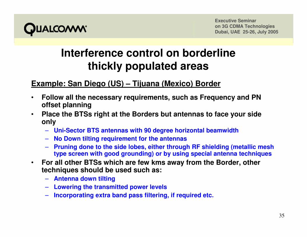
Interference control on borderline Interference control on borderline thickly populated areasthickly populated areas
Example: San Diego (US) – Tijuana (Mexico) Border
• Follow all the necessary requirements, such as Frequency and PN offset planning
• Place the BTSs right at the Borders but antennas to face your side only
– Uni-Sector BTS antennas with 90 degree horizontal beamwidth– No Down tilting requirement for the antennas– Pruning done to the side lobes, either through RF shielding (metallic mesh
type screen with good grounding) or by using special antenna techniques• For all other BTSs which are few kms away from the Border, other
techniques should be used such as:– Antenna down tilting – Lowering the transmitted power levels– Incorporating extra band pass filtering, if required etc.
Executive Seminar on 3G CDMA TechnologiesDubai, UAE 25-26, July 2005
36
Presentation OutlinePresentation Outline
• CDMA Spectrum Allocation plans
• Why do we need coordination in border areas?– Propagation Characteristics comparison
– What Regulators have to do?
– What Service Providers have to do?
• Techniques to control Network Access
• Techniques to control Cross-border Interference
•• ConclusionsConclusions
Executive Seminar on 3G CDMA TechnologiesDubai, UAE 25-26, July 2005
37
ConclusionsConclusions
• Cross-border coordination among CDMA as well as also other operators is required to utilize the spectrum very effectively
• For sparsely populated border areas, it is alright to go with easy and interference free preferential frequency planning/allocation
• With proper Field strength and PN offset planning, there will be around a nominal degradation in capacity due to co-channel and adjacent-channel interference
– This capacity reduction is much better than the reductions that we encounter in the preferential frequency allocations
• Lowering the power levels for the border area BTSs and down tilting the BTS transmit antennas are the other techniques used to curb interference effects
• For thickly populated bordering towns/cities, putting BTSs right at the border and transmit only towards your side is one of the best solution
Executive Seminar on 3G CDMA TechnologiesDubai, UAE 25-26, July 2005
38
Any Questions Please?Any Questions Please?

Executive Seminar on 3G CDMA TechnologiesDubai, UAE 25-26, July 2005
39
Thank You !
Feel free to contact us for any additional information
Mullaguru [email protected]