


Languages
Pages
Legal

Reservoir Purge Valve (RPV)Installation Instructions
L31281Rev. 8/17
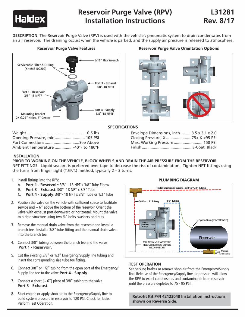
DESCRIPTION: The Reservoir Purge Valve (RPV) is used with the vehicle’s pneumatic system to drain condensates from an air reservoir. The draining occurs when the vehicle is parked, and the supply air pressure is released to atmosphere.
INSTALLATIONPRIOR TO WORKING ON THE VEHICLE, BLOCK WHEELS AND DRAIN THE AIR PRESSURE FROM THE RESERVOIR.NPT FITTINGS: Liquid sealant is preferred over tape to decrease the risk of contamination. Tighten NPT fittings using the turns from finger tight (T.F.F.T.) method, typically 2 – 3 turns.
Weight ......................................................0.5 lbsOpening Pressure, min ........................... 105 PSIPort Connections ...............................See AboveAmbient Temperature ................ -40°F to 180°F
Envelope Dimensions, inch ..........3.5 x 3.1 x 2.0Closing Pressure, X .......................75< X <95 PSIMax. Working Pressure .......................... 150 PSIFinish ............................................. E-Coat, Black
SPECIFICATIONS
Reservoir Purge Valve Features Reservoir Purge Valve Orientation Options
PLUMBING DIAGRAM
Port 1 - Reservoir3/8”-18 NPTF
5/16” Hex Wrench
Port 3 - Exhaust3/8”-18 NPTF
Port 4 - Supply3/8”-18 NPTF
1. Install fittings into the RPV: A. Port 1 - Reservoir: 3/8” - 18 NPT x 3/8” Tube Elbow B. Port 3 - Exhaust: 3/8” -18 NPT x 3/8” Tube C. Port 4 - Supply: 3/8”- 18 NPT x 3/8” Tube or 1/2” Tube
2. Position the valve on the vehicle with sufficient space to facilitate service and ~ 6” above the bottom of the reservoir. Orient the valve with exhaust port downward or horizontal. Mount the valve to a rigid structure using two ¼” bolts, washers and nuts.
3. Remove the manual drain valve from the reservoir and install a branch tee. Install a 3/8” tube fitting and the manual drain valve into the branch tee.
4. Connect 3/8” tubing between the branch tee and the valve Port 1 - Reservoir.
5. Cut the existing 3/8” or 1/2” Emergency/Supply line tubing and insert the corresponding size tube tee fitting.
6. Connect 3/8” or 1/2” tubing from the open port of the Emergency/ Supply line tee to the valve Port 4 - Supply.
7. Connect a short [~ 6”] piece of 3/8” tubing to the valve Port 3 - Exhaust.
8. Start engine or apply shop air to the Emergency/Supply line to build system pressure in reservoir to 120 PSI. Check for leaks. Perform Test Operation.
TEST OPERATIONSet parking brakes or remove shop air from the Emergency/Supply line. Release of the Emergency/Supply line air pressure will allow the RPV to expel condensates and contaminants from reservoir until the pressure depletes to 75 - 95 PSI.
Retrofit Kit P/N 42123048 Installation Instructions shown on Reverse Side.
Mounting Bracket2X O.27” Holes, 2” Center
Serviceable Filter & O-Ring(Kit #48100200)
4
3
1
1
3
4
4
3
1
4
3
1
Trailer Emergency/ Supply – 3/ 8” or 1/ 2’’ Tubing
3/ 8” Tubing
Manual Drain Valve
Reservoir
RESERVOIR (IN)
PORT [1]
EXHAUST PORT [3]
MOUNT VALVE 6” ABOVE THE RESERVOIR BOTTOM DRAIN IS
RECOMMENDED
Siphon Drain [IF APPLICABLE] SUPPLY
(CONTROL)PORT [4]
3/ 8”or 1/ 2’’ Tubing
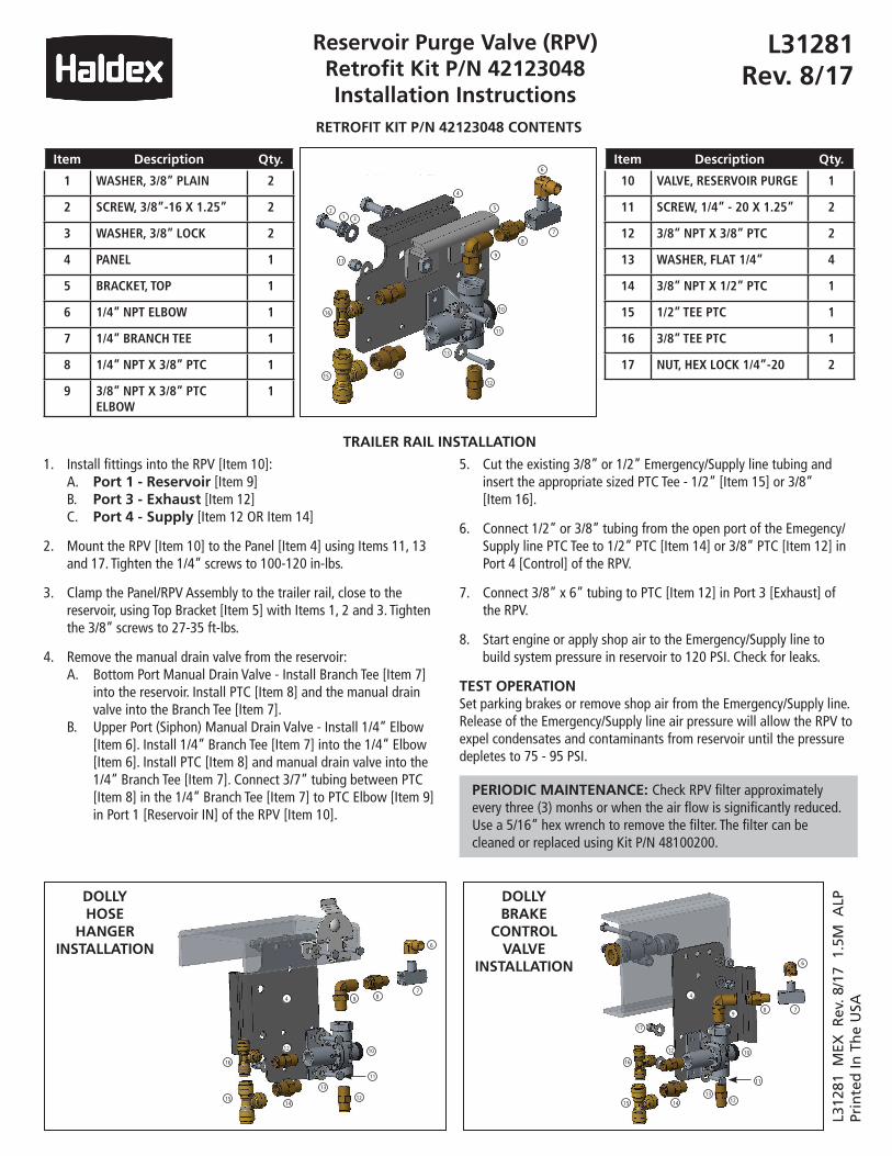
Reservoir Purge Valve (RPV)Retrofit Kit P/N 42123048 Installation Instructions
L31281Rev. 8/17
Item Description Qty.
1 WASHER, 3/8” PLAIN 2
2 SCREW, 3/8”-16 X 1.25” 2
3 WASHER, 3/8” LOCK 2
4 PANEL 1
5 BRACKET, TOP 1
6 1/4” NPT ELBOW 1
7 1/4” BRANCH TEE 1
8 1/4” NPT X 3/8” PTC 1
9 3/8” NPT X 3/8” PTC ELBOW
1
Item Description Qty.
10 VALVE, RESERVOIR PURGE 1
11 SCREW, 1/4” - 20 X 1.25” 2
12 3/8” NPT X 3/8” PTC 2
13 WASHER, FLAT 1/4” 4
14 3/8” NPT X 1/2” PTC 1
15 1/2” TEE PTC 1
16 3/8” TEE PTC 1
17 NUT, HEX LOCK 1/4”-20 2
1. Install fittings into the RPV [Item 10]: A. Port 1 - Reservoir [Item 9] B. Port 3 - Exhaust [Item 12] C. Port 4 - Supply [Item 12 OR Item 14]
2. Mount the RPV [Item 10] to the Panel [Item 4] using Items 11, 13 and 17. Tighten the 1/4” screws to 100-120 in-lbs.
3. Clamp the Panel/RPV Assembly to the trailer rail, close to the reservoir, using Top Bracket [Item 5] with Items 1, 2 and 3. Tighten the 3/8” screws to 27-35 ft-lbs.
4. Remove the manual drain valve from the reservoir: A. Bottom Port Manual Drain Valve - Install Branch Tee [Item 7] into the reservoir. Install PTC [Item 8] and the manual drain valve into the Branch Tee [Item 7]. B. Upper Port (Siphon) Manual Drain Valve - Install 1/4” Elbow [Item 6]. Install 1/4” Branch Tee [Item 7] into the 1/4” Elbow [Item 6]. Install PTC [Item 8] and manual drain valve into the 1/4” Branch Tee [Item 7]. Connect 3/7” tubing between PTC [Item 8] in the 1/4” Branch Tee [Item 7] to PTC Elbow [Item 9] in Port 1 [Reservoir IN] of the RPV [Item 10].
5. Cut the existing 3/8” or 1/2” Emergency/Supply line tubing and insert the appropriate sized PTC Tee - 1/2” [Item 15] or 3/8” [Item 16].
6. Connect 1/2” or 3/8” tubing from the open port of the Emegency/ Supply line PTC Tee to 1/2” PTC [Item 14] or 3/8” PTC [Item 12] in Port 4 [Control] of the RPV.
7. Connect 3/8” x 6” tubing to PTC [Item 12] in Port 3 [Exhaust] of the RPV.
8. Start engine or apply shop air to the Emergency/Supply line to build system pressure in reservoir to 120 PSI. Check for leaks.
TEST OPERATIONSet parking brakes or remove shop air from the Emergency/Supply line. Release of the Emergency/Supply line air pressure will allow the RPV to expel condensates and contaminants from reservoir until the pressure depletes to 75 - 95 PSI.
TRAILER RAIL INSTALLATION
PERIODIC MAINTENANCE: Check RPV filter approximately every three (3) monhs or when the air flow is significantly reduced. Use a 5/16” hex wrench to remove the filter. The filter can be cleaned or replaced using Kit P/N 48100200.
RETROFIT KIT P/N 42123048 CONTENTS
17
21 3
16
15 14
13
12
11
10
9
8
7
6
5
4
6
16
1514
13
12
11
10
7894
12
17
16
15
12
14
13
4
11
12
10
8 7
6
9
DOLLY HOSE
HANGER INSTALLATION
DOLLY BRAKE
CONTROL VALVE
INSTALLATION
L312
81 M
EX R
ev. 8
/17
1.5
M A
LPPr
inte
d In
Th
e U
SA
Top Related