


Languages
Pages
Legal

1
SPL IRONPlugin Manual
Developed by Brainworx Audio in partnership with SPL electronics GmbH distributed by Plugin Alliance
2
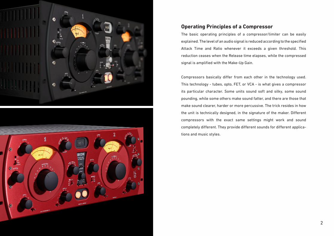
Operating Principles of a CompressorThe basic operating principles of a compressor/limiter can be easily
explained. The level of an audio signal is reduced according to the specified
Attack Time and Ratio whenever it exceeds a given threshold. This
reduction ceases when the Release time elapses, while the compressed
signal is amplified with the Make-Up Gain.
Compressors basically differ from each other in the technology used.
This technology - tubes, opto, FET, or VCA - is what gives a compressor
its particular character. Some units sound soft and silky, some sound
pounding, while some others make sound fatter, and there are those that
make sound clearer, harder or more percussive. The trick resides in how
the unit is technically designed, in the signature of the maker. Different
compressors with the exact same settings might work and sound
completely different. They provide different sounds for different applica-
tions and music styles.
2

33
IRON Mastering CompressorThe IRON mastering compressor is not a copy of a classic unit, but rather
an original concept in itself. Our goal was to conceive a compressor
that provided a pleasant, melodic-sounding, transparent compression,
inspired on the vintage compressors of the radio era. And we wanted it to
be versatile enough to adapt perfectly to the needs of modern mastering
studios. Thus, the IRON combines not only the sonic virtues of legendary
vintage tube compressors with the advantages of the High Dynamic 120 V
operating voltage in a single unit. It also sets a new benchmark in terms
of tube compressor technology, with the innovative implementation of a
parallel dual-tube circuit. Thanks to the especially conceived Mu-Metal
IRON transformers, the signal of each channel is split across two
different twin-triode tubes. The combination of the different response
curves of both tubes results in a transparent and musically pleasant
compression. Additionally, peak signals of the control voltage are limited
by a feed-forward resistive opto-isolator. Thus, the output signal remains
lively even with a high gain reduction. The compression is only noticeable
with extreme settings.
But mastering is not the only domain where the IRON sets new standards.
It can also be used to process individual instruments, like vocals, bass,
guitar, strings, etc. The IRON is also an excellent option for subgroups.

4
120 Volt Technology
SPL‘s goal was to push analog signal processing to the limits. That‘s why
we combined the best possible components with a high-grade optimized
circuit design.
We have been using the in-house developed 120-volt technology - the
highest-ever operating voltage used for audio applications - in all our
products from the Mastering series for years. Some of the most highly
respected Mastering studios today revolve around SPL consoles and
signal processors from our Mastering series (Bob Ludwigs Gateway
Mastering & DVD in the USA, Simon Heyworth‘s Super Audio Mastering in
the UK, Galaxy Studios in Belgium, and the legendary Wisseloord in the
Netherlands, for instance). The 120-volt technology is based on op-amps
developed internally by SPL‘s co-founder and Chief Developer Wolfgang
Neumann. The IRON features the most advanced generation of these
op-amps. They boast better tech specs thanks to the thermal behavior
optimization they underwent under the hands of Bastian Neu.
Ultimately, the supply voltage is key for the overall dynamic response of
a processor. Voltage is to an electrical circuit what cylinder capacity is to
an internal combustion engine.
You can‘t replace cylinder capacity with anything else, except more
cylinder capacity.
120 Volt Technology - Diagram
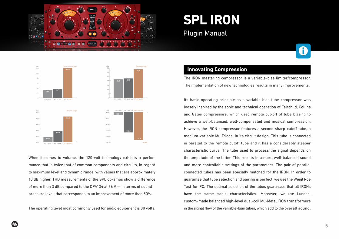
These diagrams clearly show the advantages of our 120-volt technology
in comparison to other circuits with a lower operating voltage. The direct
relation between operating level and maximum level is fundamental for
the classification: the higher the operating level, the higher the maximum
level a circuit can handle. And since virtually all essential acoustic and
musical parameters depend on this relation, a higher operating voltage
also has a positive impact on the dynamic range, distortion limit and
signal-to-noise ratio. The result is a clearly more laid-back and natural
sound with less unpleasant coloring.
Do bear in mind that dB scales do not represent linear but rather
exponential increases. A 3 dB increase corresponds to doubling the
acoustic power, +6 dB correspond to twice the sound pressure level, and
+10 dB correspond to twice the perceived loudness.
SPL IRONPlugin Manual
5
120
125
130
135
140
145dBu Dynamic Range
OPA 134@30 V OPA 134@36 V SPL-OP@120V
124,2
129,1
141,4
0
5
10
15
20
25
30
35dBu
OPA 134@30 V OPA 134@36 V SPL-OP@120V
21,5 22,5
33,2
Maximum Levels
0
20
40
60
80
100
120Volt
+/- 15 Volt +/- 18 Volt +/- 60 Volt
30 V36 V
120 V
Operational Voltages
-115
-113
-111
-109
-107
-105dBu TL 071@30 V OPA 134@36 V SPL-OP@120V
106
111,7
114,2
THD&N
When it comes to volume, the 120-volt technology exhibits a perfor-
mance that is twice that of common components and circuits, in regard
to maximum level and dynamic range, with values that are approximately
10 dB higher. THD measurements of the SPL op-amps show a difference
of more than 3 dB compared to the OPA134 at 36 V — in terms of sound
pressure level, that corresponds to an improvement of more than 50%.
The operating level most commonly used for audio equipment is 30 volts.
Innovating Compression
The IRON mastering compressor is a variable-bias limiter/compressor.
The implementation of new technologies results in many improvements.
Its basic operating principle as a variable-bias tube compressor was
loosely inspired by the sonic and technical operation of Fairchild, Collins
and Gates compressors, which used remote cut-off of tube biasing to
achieve a well-balanced, well-compensated and musical compression.
However, the IRON compressor features a second sharp-cutoff tube, a
medium-variable Mu Triode, in its circuit design. This tube is connected
in parallel to the remote cutoff tube and it has a considerably steeper
characteristic curve. The tube used to process the signal depends on
the amplitude of the latter. This results in a more well-balanced sound
and more controllable settings of the parameters. The pair of parallel
connected tubes has been specially matched for the IRON. In order to
guarantee that tube selection and pairing is perfect, we use the Weigl Roe
Test for PC. The optimal selection of the tubes guarantees that all IRONs
have the same sonic characteristics. Moreover, we use Lundahl
custom-made balanced high-level dual-coil Mu-Metal IRON transformers
in the signal flow of the variable-bias tubes, which add to the overall sound.
SPL IRONPlugin Manual
6
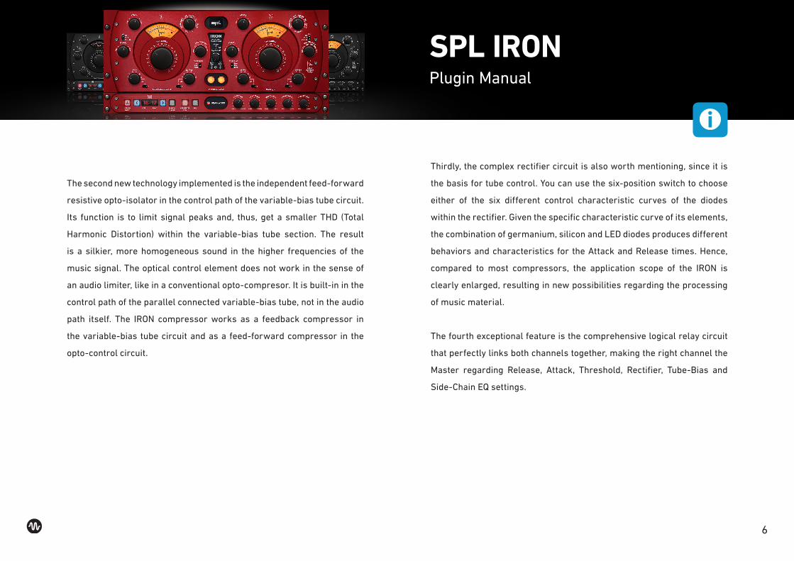
The second new technology implemented is the independent feed-forward
resistive opto-isolator in the control path of the variable-bias tube circuit.
Its function is to limit signal peaks and, thus, get a smaller THD (Total
Harmonic Distortion) within the variable-bias tube section. The result
is a silkier, more homogeneous sound in the higher frequencies of the
music signal. The optical control element does not work in the sense of
an audio limiter, like in a conventional opto-compresor. It is built-in in the
control path of the parallel connected variable-bias tube, not in the audio
path itself. The IRON compressor works as a feedback compressor in
the variable-bias tube circuit and as a feed-forward compressor in the
opto-control circuit.
SPL IRONPlugin Manual
Thirdly, the complex rectifier circuit is also worth mentioning, since it is
the basis for tube control. You can use the six-position switch to choose
either of the six different control characteristic curves of the diodes
within the rectifier. Given the specific characteristic curve of its elements,
the combination of germanium, silicon and LED diodes produces different
behaviors and characteristics for the Attack and Release times. Hence,
compared to most compressors, the application scope of the IRON is
clearly enlarged, resulting in new possibilities regarding the processing
of music material.
The fourth exceptional feature is the comprehensive logical relay circuit
that perfectly links both channels together, making the right channel the
Master regarding Release, Attack, Threshold, Rectifier, Tube-Bias and
Side-Chain EQ settings.

7
Signal Flow
The following diagram depicts the signal flow within the IRON compressor.
It is meant to clarify how it works and to show the relation between its
different parameters. The audio signal flow is in blue and the control
voltage signal flow is in green.
OUTPUT
2
4
6 8 10 12
INPUT
THRESHOLD
Threshold
min
2
4
6
8
10
12
1
4
18
20 22 24 26 28 30 32 34 36 38 40 max
Input Gain
Input Output
Rectifier
1mF
2mF 3
.3mF 330nF 220nF 100nF
RECTIFIER
Ge
G
e L
ED S i Ge Ge/S i
Side Chain EQs
OFF
EQ
1 EQ 2 EQ 3 EQ 4 EXT.
SIDE CHAIN EQs
Anode
Variable-µ /Sharp Cut-off Tube
Variable-µ /Remote Cut-off Tube
Grid
Cathode
Tube BiasHigher Bias =
More GainReduction
Audio
Control Voltages
Attack
fast
•
• • • slow
ATTACK
Releasefa
st
•
• • • slow
RELEASE
Transformer
TUBE BIASLowM idHigh
Anode
Grid
Cathode
– +0
1
2
3 5 8 12
Output Gain
– +0
TransformerOpto
Peak Limiter
AirBass/Tape Roll-Off
AirBass
12AX7ECC83
Perkin ElmerVTL 5C1
12AU7ECC82
SPL IRONPlugin Manual
Suggestions for setting the compressor
The operation of the IRON compressor strongly depends on the input
signal. Normally the following start values are a good starting point:
Attack/Release: Position 2 or 3 (clockwise from „fast“)
Rectifier: LED
Side Chain EQs: Off
Tube Bias: Low
If you switch through the different rectifiers, you have to adjust the other
parameters. The remaining rectifier circuits tend to provide faster/slower
time values. When the program material stays the same, slower/longer
time values should be chosen and/or the threshold should be raised.
Especially when it comes to group applications, the high bias setting can
be interesting.

8
1 Input
The operating value of each channel can be increased or reduced in 2 dB
steps via the sixstep rotary knob. A three-way switch allows you to select
whether the value is increased or decreased. In the center position, the
Input switch is inactive; in other words, no level increase nor reduction
takes place. If the switch is in the „-“ position (left), the input level is
reduced according to the chosen setting. If the switch is in the „+“ position
(right), the input level is increased according to the chosen setting.
The increase or reduction of the input level affects the overall response of
the compressor and it has a direct impact on the level reduction.
2 Output
Since the compressor reduces the dynamics of the incoming signal,
the output level is, generally speaking, lower than the input level. This
audible level loss can be compensated with the Output control, in order to
make the best use of the recording medium used. Just like with the input
section, the increase or reduction is achieved via a threeway switch. In
the center position, the Output switch is inactive; in other words, no level
increase nor reduction takes place.
SPL IRONPlugin Manual
If the switch is in the „-“ position (left), the Output level is reduced
according to the chosen setting. If the switch is in the „+“ position (right),
the Output level is increased according to the chosen setting.
3 Threshold
Threshold determines the level beyond which the compressor starts to
compress. The compressor begins to process the signal once the threshold
value has been exceeded. Only signals that exceed the threshold level
are compressed. Signals whose level is beneath the threshold value are
not processed. Do note, however, that the intensity of the compression
depends also on the Input, Tube Bias, Rectifi er, Attack, Release, and Side
Chain EQs parameters.
21
3
9
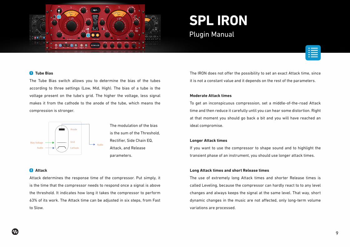
1 Tube Bias
The Tube Bias switch allows you to determine the bias of the tubes
according to three settings (Low, Mid, High). The bias of a tube is the
voltage present on the tube‘s grid. The higher the voltage, less signal
makes it from the cathode to the anode of the tube, which means the
compression is stronger.
Cathode
GridBias Voltage
AudioAudio
AnodeThe modulation of the bias
is the sum of the Threshold,
Rectifier, Side Chain EQ,
Attack, and Release
parameters.
2 Attack
Attack determines the response time of the compressor. Put simply, it
is the time that the compressor needs to respond once a signal is above
the threshold. It indicates how long it takes the compressor to perform
63% of its work. The Attack time can be adjusted in six steps, from Fast
to Slow.
SPL IRONPlugin Manual
The IRON does not offer the possibility to set an exact Attack time, since
it is not a constant value and it depends on the rest of the parameters.
Moderate Attack times
To get an inconspicuous compression, set a middle-of-the-road Attack
time and then reduce it carefully until you can hear some distortion. Right
at that moment you should go back a bit and you will have reached an
ideal compromise.
Longer Attack times
If you want to use the compressor to shape sound and to highlight the
transient phase of an instrument, you should use longer attack times.
Long Attack times and short Release times
The use of extremely long Attack times and shorter Release times is
called Leveling, because the compressor can hardly react to to any level
changes and always keeps the signal at the same level. That way, short
dynamic changes in the music are not affected, only long-term volume
variations are processed.
1
2

10
1 Release
The counterpart of the Attack is Release. The Release parameter
determines how fast the compressor eases processing the signal. To
be precise, it determines the time in which 63% of the reduced gain is
restored. Similarly to the Attack time, the Release time can also be set in
six steps from Fast to Slow. Likewise, exact Release time settings are not
possible. Once again, there are no constant values, since the Release time
depends on the rest of the parameters, too.
Although the Attack and Release times can be considered fixed intervals,
the control-time behavior and operating mode of the tubes is very
different depending on the music. That is why these values should not be
considered absolute values.
On page 15 you will find an overview for orientation, which shows the time
values depending on the chosen rectifiers.
SPL IRONPlugin Manual
TIP
Compression during vocal recordings
The attack time should not be too fast, otherwise plosives could be
distorted, resulting in the vocals sounding unnatural. Many sound
engineers compensate these level variations by automating the fader. The
actual peaks of vocals are not at the beginning of a syllable, but rather
later, when long vocals come along, which ought to be limited as well.
That is why the Attack time should be relatively slow and the Release time
relatively fast.
2 Rectifier
To produce the bias voltage to control the parallel connected tubes we
use a rectifier. This circuit has six different operating characteristics
(different rectifiers), which can be selected with the corresponding
switch. They have a direct impact on the Attack and Release times.
In comparison to the other rectifiers, the rectifier circuit LED delivers the
longest/slowest time values. You can find more information at the time
values overview on page 15.
1
2

11
1 Side Chain EQs
The Sidechain filters can make the response of the compression be influ-
enced by a given frequency range. Some call this frequency-selective
compression. For instance, if the low frequencies are reduced, the
compressor will not react as promptly to kick drums and bass lines.
This can prove very useful when these elements are very present in the
material used. The same applies the other way around. If you increase
certain frequencies, the compressor will respond more resolutely to
them. The Sidechain filters are only in the control signal path.
The IRON mastering compressor‘s Side Chain EQ features a six-step
switch that allows you to choose between Off, four sidechain-filter presets
or an external sidechain signal. In the Off position the only filtering that
applies is due to a condenser that filters out frequencies below 20 Hz.
Position 3-5 provide empirically determined, preset filter curves.
In the following diagram you can see the frequency response curves of the
different filter presets. The frequency response curve of the filter presets
are shown in different colors to make them easily distinguishable.
SPL IRONPlugin Manual
02-
2+
81-
61-
41-
21-
01-
8-
6-
4-
2-
0-
dBu
02 k0305 001 002 005 k1 k2 k5 k01 k02zH
Off
Preset 1
Preset 2
Preset 3
Preset 4
Ratio
This type of compressor does not have a fixed ratio. The lower the
Threshold and the higher the input signal, the stronger the compression.
This is actually one of the main factors that make the IRON‘s compression
so musical.
1
12
1 Auto Bypass / Host Sync / Interval
To be able to make an objective judgment of the processed material, it is
best not to have to be toggling between the original and processed signals by
yourself, but rather have it done automatically. Plus, the fact that you do not
have to move from the sweet spot and can concentrate better on the music
to optimally assess the processing is a huge advantage. The Interval control
determines the time that needs to elapse before the compressor toggles
between the processed and unprocessed signals. Hard left is the shortest
setting. To increase the interval, turn the knob clockwise. Set to Host Sync for
synchronising the Auto Bypass to your DAW.
When Host Sync is on, Interval times are in BARS.
When Auto Bypass is on, interval times are in seconds.
SPL IRONPlugin Manual
3 AirBass / Bypass / Tape Roll-Off
Many times, you might want to give that distinctive touch to a music
production at the very end of the production process, without the need
to modify or redo the entire signal chain. It was with this in mind that we
developed two specially matched passive filters and integrated them into
a 120-volt SUPRA op-amp.
AirBass:
This filter makes music rounder and more well-balanced with powerful
lows and bright, silky highs.
Tape Roll-Off:
This filter is based on the frequency response of tape machines. It can
prove very useful to provide a nice rounding-off in the high end when the
material being processed is too shrill.
In the following diagram you can see the frequency response curves for the
AirBass and Tape Roll-Off presets, as well as that of the Bypass switch.
1
2

13
6-
5-
4-
3-
2-
1-
0-
1+
2+
3+
4+
5+
dBu
02 k0505 001 002 005 k1 2k k5 k01 k02zH
Bypass
AirBass
Tape Roll-Off
1 SC Link - Sidechain Link
The IRON mastering compressor has been designed as a completely
independent two-channel, dual-mono compressor and can be used to
process two different mono signals at the same time. Nevertheless, you
can also easily process a stereo signal, since all settings are made with
switches or a detent potentiometer (Threshold). This allows you to effort-
lessly make the same settings on the left and right channels.
SPL IRONPlugin Manual
The components of both channels have been especially selected so that
the difference between them is as little as possible, considering a very
small tolerance range.
However, if you activate the Link function. all settings of the link channel
are applied to the right channel thanks to an intelligent logical relay
circuit. This is true for the Threshold, but also for the Attack, Release,
Bias, Side Chain EQ, and Rectifier settings.
The combination of both control voltages makes it easier to process a
stereo signal more precisely. It allows you to concentrate on the music
without having to worry about correcting a parameter on the other
channel.
And it can also be put to use creatively. For instance, with the Link function
not activated, a sound that only exceeds the Threshold on the left channel
would trigger the compression on the left channel only. However, if the
Link function is activated, the right channel is compressed, too. When
processing stereo signals in dual-mono mode, the stereo image is still
acoustically perceived.
1

14
1 VU Switch
Use this three-way switch to toggle the display between Gain Reduction
and Output level (0dB and +10 dB). This can be done for each of the two
VU-meters separately. The meters work independently for each channel,
even when the Link function is activated.
0 dB on the VU-meter correspond to an output level of 0 dBu.
The internal reference level corresponding to 0 VU can be set in the
“About” dialog, which is brought up by clicking on the SPL Logo.
The default internal reference level:
-18dbFS - 0 VU
-8dbFS - +10 VU
1 Channel Switch
The two, centrally located, orange-lit switches activate or deactivate the
corresponding left and right channels.
SPL IRONPlugin Manual
Time values depending on the rectifiers
Although the Attack and Release times can be considered fixed intervals,
the control-time behavior and operating mode of the tubes is very
different depending on the music. That is why these values should not be
considered absolute values. The following chart should give an overview
of the dependence of the control times of the input signal and the chosen
rectifier, with the same use of the Side Chain EQ Preset (EQ1). Attack
and Release were measured and switched in sequence from Fast (A + R
Position 1) to Slow (A + R Position 6). The time values were measured with
an input signal with the frequency of 10kHz.
2
1

15
SPL IRONPlugin Manual
A + R Position Attack (msec) Release (msec) Rectifier
1
2
3
4
5
6
0,1
6
10
18
30
50
100
150
180
200
220
250
GE 1mF
GE 1mF
GE 1mF
GE 1mF
GE 1mF
GE 1mF
1
2
3
4
5
6
1
15
30
40
50
70
300
450
500
600
700
900
GE 2mF
GE 2mF
GE 2mF
GE 2mF
GE 2mF
GE 2mF
1
2
3
4
5
6
3
35
70
100
150
220
600
1000
1700
2500
3200
5000
LED 3.3 mF
LED 3.3 mF
LED 3.3 mF
LED 3.3 mF
LED 3.3 mF
LED 3.3 mF
A + R Position Attack (msec) Release (msec) Rectifier
1
2
3
4
5
6
0,5
3
5
8
9
12
80
120
160
180
220
300
Si. 330 nF
Si. 330 nF
Si. 330 nF
Si. 330 nF
Si. 330 nF
Si. 330 nF
1
2
3
4
5
6
0,3
1,5
3
5
7
9
30
50
70
80
120
130
Ge 220 nF
Ge 220 nF
Ge 220 nF
Ge 220 nF
Ge 220 nF
Ge 220 nF
1
2
3
4
5
6
0,2
0,7
1,5
2,5
4
6
20
40
60
80
100
170
Ge/Si 100nF
Ge/Si 100nF
Ge/Si 100nF
Ge/Si 100nF
Ge/Si 100nF
Ge/Si 100nF
16
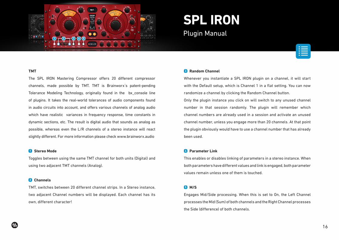
TMT
The SPL IRON Mastering Compressor offers 20 different compressor
channels, made possible by TMT. TMT is Brainworx s patent-pending
Tolerance Modeling Technology, originally found in the bx_console line
of plugins. It takes the real-world tolerances of audio components found
in audio circuits into account, and offers various channels of analog audio
which have realistic variances in frequency response, time constants in
dynamic sections, etc. The result is digital audio that sounds as analog as
possible, whereas even the L/R channels of a stereo instance will react
slightly different. For more information please check www.brainworx.audio
1 Stereo Mode
Toggles between using the same TMT channel for both units (Digital) and
using two adjacent TMT channels (Analog).
2 Channels
TMT, switches between 20 different channel strips. In a Stereo instance,
two adjacent Channel numbers will be displayed. Each channel has its
own, different character!
SPL IRONPlugin Manual
3 Random Channel
Whenever you instantiate a SPL IRON plugin on a channel, it will start
with the Default setup, which is Channel 1 in a flat setting. You can now
randomize a channel by clicking the Random Channel button.
Only the plugin instance you click on will switch to any unused channel
number in that session randomly. The plugin will remember which
channel numbers are already used in a session and activate an unused
channel number, unless you engage more than 20 channels. At that point
the plugin obviously would have to use a channel number that has already
been used.
4 Parameter Link
This enables or disables linking of parameters in a stereo instance. When
both parameters have different values and link is engaged, both parameter
values remain unless one of them is touched.
5 M/S
Engages Mid/Side processing. When this is set to On, the Left Channel
processes the Mid (Sum) of both channels and the Right Channel processes
the Side (difference) of both channels.
1 3 4 52

17
1 Headroom
Adjusts the internal operating level so that the Plugin produces more
or less gain reduction. Rotating the control clockwise will allow signals
at the input to be pushed higher before they compress, this will result
in less compression overall. By rotating counter-clockwise headroom
is decreased resulting in a greater amount of gain reduction and more
colour and compression being added to the signal. This parameter is
perfect for fine tuning the effects produced and also for accurate level
matching.
2 HP-SC-Filter
High-Pass Filter for the Compressor Sidechain.
3 Mono Maker
This tool is a critical component to several Brainworx processors, and it is
an invaluable tool when mastering or tightening up a mix. Sweepable from
20 Hz to 20 kHz, this parameter folds the processed sound to mono at and
below the frequency set. The most common setting is between 100-200
Hz, below which bass frequencies reside, where common practice deems
that most sound should be mono. Other uses include folding an entire mix
in order to check mono compatibility and avoid phase incoherency.
SPL IRONPlugin Manual
4 Stereo Width
Make your mix wider than it originally was by increasing the Stereo Width
without losing the center of your recordings! You will not lose bass drum
power or vocals by making your mix wider this way... and it will not sound
different played back in mono at all. If you notice your Correlation Meter
(e.g. bx_meter) showing less than 90°, dial up the Mono Maker a bit to
tighten up the low-end until acceptable levels are shown.
5 Pararell Mix
Controls the amount of unprocessed signal being blended with the
processed (compressed) signal, effectively providing the option of
parallel compression.
100% = you’ll only hear compressed signal.
0% = you’ll only hear un-compressed signal.
1 2 3 4 5

18
Top Toolbar
1 Undo / Redo
You can undo and redo changes you made to the controls of the SPL IRON
plugin at any time. The Undo / Redo will work for as many as 32 steps.
This makes experimenting and tweaking knobs easy. If you don t like
what you did... just undo it.
2 Settings (A/B/C/D)
The Plugin offers four internal settings (A/B/C/D) which will be stored
with every preset. So, one preset can contain up to four settings. You may
use similar settings with more or less compression in one setup / preset.
Now, the SETTINGS can be automated in your DAW! This way it s possible
to use different sounds for your lead vocals or drums in various sections
of the song. Automate the A/B/C/D settings, and you can still tweak knobs
of the individual settings without overriding multiple parameters in your
DAW, which would be time-consuming.
SPL IRONPlugin Manual
3 Copy / Paste
To set up variations of similar sounds you don t have to dial in the settings
several times. Let s say you like your setting A and want to use the same
sound, just with less compression, as setting B.
• Simply press Copy while you are in setting A.
• Switch to setting B by pressing ‘B’ in the settings section.
• Press PASTE, now setting B is identical to setting A.
• Reduce the compression on the B setting.
Now you can switch between A & B and decide which one sounds best or
automate different settings for various sections of your session.
4 M/S Monitoring (for Stereo Channels only)
Solo M: Solos the Mid (Sum) signal being processed by the plugin.
Solo S: Solos the Side (Difference) signal processed by the plugin.
6 UI
Switches between three different User Interfaces:
RED, BLACK and ALL BLACK.
The icon closes and opens the bottom panel containing the Brainworx s
plugin only features.
1 2 3 64
19
Artist Presets
The Plugin includes presets from prominent SPL IRON users:
Brendan Duffey
Producer, Mix & Mastering Engineer (50 Cent, Megadeth/Angra, Mike
Mangini, Billy Sheehan) marked with the initials BD in the preset name.
David Reitzas
Live and Studio Engineer (multi-GRAMMY and Emmy Award winner,
Whitney Houston, Madonna, Seal, Stevie Wonder, Guns N’ Roses) marked
with the initials DR in the preset name.
SPL IRONPlugin Manual
Gentry Studer
Epicenter Mastering, Mastering Engineer (Metallica, Andrew W.K., Ryan
Adams, Incubus, Deftones, Miley Cyrus) marked with the initials GS in the
preset name.
Michael Romanowski
Coast Mastering, Mastering Engineer (Soundgarden, Pink, Evanescence,
Seal, Yes, Lady Gaga, Alanis Morisette) marked with the initials MR in the
preset name.

Top Related