


Languages
Pages
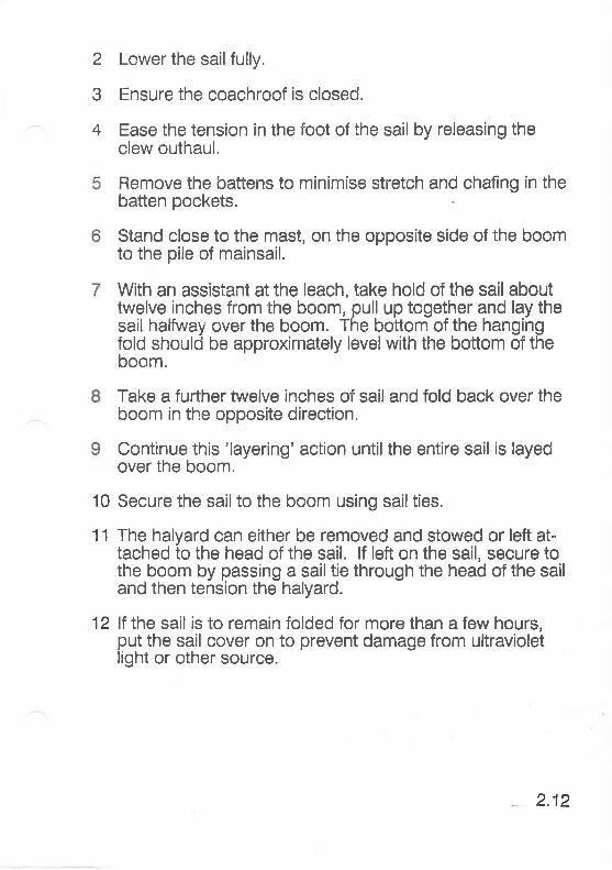
Legal

OWNER'S MANUAL
WESTERLYWesterly Yachts LimitedDcslgncc and bulldcrs of flne craft
Aston BoadWaterloovllleHampshlrePO7 7XJTel: (STD0705) 254511
This manual is provided to give Westerly yacht owner's aninsight to the cönstruction, öperation and maintenance of anew Westerly yacht.
Westerly Yachts warrants the performance of its vessels tocurrent
-specifications in accordance with Westerly Yachts
standard warranty.
Westerly Yachts reserves the right to improve its vessels orspecificätions identified in this publication without notice.
Specifications contained in this Publication (Westerly YachtsOwner's Manual - lssue 1) supersede all data published byWesterly Yachts before March 1988.
Westerly Yachts will not be held liable for any personalinjuries br damage occurring as a result of misuse or badlymaintained equipment.
Westerly Yachts advanced design and construction requiresthe striCtest of quality control, using high quality BSapproved raw materials and ancillary componentmanufacturers.
Adherence to this Owner's Manual will ensure many years oftrouble free sailing. Remember a well maintained yacht isultimately more reliable and retains a higher resale value.For further information relating to After Sales Service contactAfter Sales Manager on (STD 0705) 256406.
€i)
i::iiiit:ti:ti:t:,i::.iäiii:iiiiti::.:::.li ::|:l:ll:;i:|:;GENtENtS
Title
INTRODUCTION
CONTENTS
EQUIPMENT CHART - CURRENT YACHTS
SECTION 1 - HULLConstructionSkin Fittings and SeacocksCathodic ProtectionAntifouling
SECTION 2 - SAILS AND RIGGINGTypes of RigStanding RiggingMast VibrationSailsFolding SailsSetting SailsHalyard Clutches
SECTION 3 - STEERING SYSTEMSRuddersWheel Steering SystemsHydraulic Steering
SECTION 4 - ENGINE SYSTEMSEngine SystemsFuel SystemsCooling SystemsExhaust SystemsEngine ControlsEngi ne lnstru mentationBasic Engine CareTurbochargers
Page
(ii)
(iii)
(vi)
1.11.21.41.5
2.12.32.102.112.112.132.20
3.13.53.6
4.14.14.34.44.54.64.64.10
(iii)
Title
Stern Gear
SECTION5-GASSYSTEMSGas System
SECTION 6 . WATER/WASTE SYSTEMSEquipment ChartWater SystemsWaste SystemsBrydon Marine ToiletBrydon Toilet with Holding Tank
SECTION 7 - ELECTRICAL SYSTEMSBasic Electrical SystemBatteriesBattery lsolation SwitchesSwitch PanelsPowercentreIYS Switch Panel
SECT]ON 8 - MAINTENANCEHullSails and RiggingSteering SystemsEngine SystemsGas SystemsWaterruaste SystemsWi nterisation/DewinterisationGleaning
Page
4.12
5.1
6.16.26.26.26.4
7.17.27.27.47.47.8
8.18.88.98.118.158.158.158.19
(iv)
Tirle
SECTION 9 - SPEClFICATIONSKonsort 29Konsort DuoTempest 31Fulmar 32Storm 33Storm 33 CruisingRiviera 35Seahawk 35Falcon 35Corsair ll 36 - SloopSealord 39 - SloopOceanlord 40 - Sloop
SECTION 1O _ WESTERLY YACHTS _ PRE 1988lntroductionEquipment Charts
Page
9.19.29.39.49.59.5A9.589.69.79.89.99.10
10.114.2
SECTION 11 - STEERING SYSTEMS - PRE 1988Whitlock Systems 11 .1
SECTION 12 _ ENIGINE SYSTEMS _ PRE 1988Engine Systems 12.1Stern Gear 12.1
SECTION 13 - WATERMASTE SYSTEMS - PRE 1988Lavac Marine Toilet 13.1Lavac Toilet with Holding Tank 13.2SL 400 Series Marine Toilet 13.5
(v)
)
WESTERLY YACHT EQUIPMENT CHART
CIJRRENT PRODI,.!CTION YACHTS
STORM CRUISING Twin Sloop
YACHT
KONSORT
KONSORT DUO
TEMPEST
FULMAR
STORM
RIVIERA
SEAHAWK
FALCON
CORSAIR
OCEANLORD
KEEL RIG
Finffwin Sloop
Twin Sloop
Fin/Twin Sloop
Fin Sloop/3/4
Fin Sloop
Fin/Twin Sloop
Fin/Twin Sloop
Finffwin Sloop
Fin Sloop
Fin Sloop
STEERING
Tiller
Tiller/Hyd
Tiller
Tiller/Wheel
Tiller
Tiller/Wheel
Hydraulic
Edson Wheel
Edson Wheel
Edson Wheel
Edson Wheel
ENGINE
Volvo 2002
Volvo 2003
Volvo 2002
Volvo 2002
Volvo 2002
Volvo 2003
Volvo 2003
Volvo 2003
Volvo 2003
Volvo 2003/20037
Volvo 20037
BARLOW WINCH
20c & 21c
21c
24c & 18c
6/16 & 6.5/34
25c &27c
24c &22c
17c & 24c
19c & 25c
19c & 25c
6.6t24 & 10.8/44.6
24c &25c &32c
(vi)
RUDDER
Transom
Transom
Spade
Spade
Spade
Spade
Spade
Spade
Spade
Spade
Spade
1
CONSTRUCTION
SKIN FITTINGS AND SEACOCKSSkin Fitting Gate ValveSkin Fitting Sleeve ValveSkin Fitting Ball Valve
CATHODIC PROTECTIONAttachmentBondingReplacement
ANTIFOULING
CONSTRUCTION
The main hull and deck is manufactured using GlassReinforced Plastic (GRP). GRP matting and a polyester resinare laminated in moulds to produce the hull and deckshapes. The outer suffaces have a gelcoat layerapproximately 1mm thick which provides a water resistantskin.
Three types of GRP are used: Unidirectional mat for highstrength and reinforcing, woven roving for high strength andreinforcing, chopped strand Mat (CSM) for intricatemouldings.
PVC foam is used in deck and coach roof mouldings forstrength. lt is light in weight and does not absorb water.
CSM CompositeTop Skin
CSM Composite BottomSkln With Woven Rovings
Fig. 1 - PVC Foam Sandwich
Plywood is used in high load areas such as stanchionbases. Aluminium plate is used at the mast heel plinth forhigh strength.
Hull using bulkheads and stringers.The polyurethane foam formersover inside of the hull and underside ofthe deck. Plywood can be used as an alternative.
1.1

The most important structural area is in the region of thekeel attachment. This is heavily reinforced withpolyurethane foam overlaid with GRP to withstand thetremendous forces exerted.
SKIN FITTINGS AND SEACOCKS
resistant material such as bronze, stainless steel or plastic.They are either integrated with, or associated with, aseacock. The exception is where they are used to allow hullpenetration for log or echo sounder transducers, etc.
The three types of seacock currently fitted to WesterlyYachts are:
Skln Fitting Gate Valve
Application: Used for engine cooling with Volvo remotefilter, sink drain outlet and cockpit drains.
Operation: Turn tap anti-clockwise to open and clockwiseto close.
Frg.2- Gate Valve
1.2
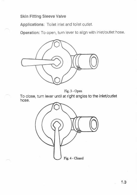
Skin Fitting Sleeve Valve
Applications: Toilet inlet and toilet outlet.
Operation: To open, turn lever to align with inlet/outlet hose.
Fig.3 - Open
To close, turn lever until at right angles to the inlet/outlethose.
1.3
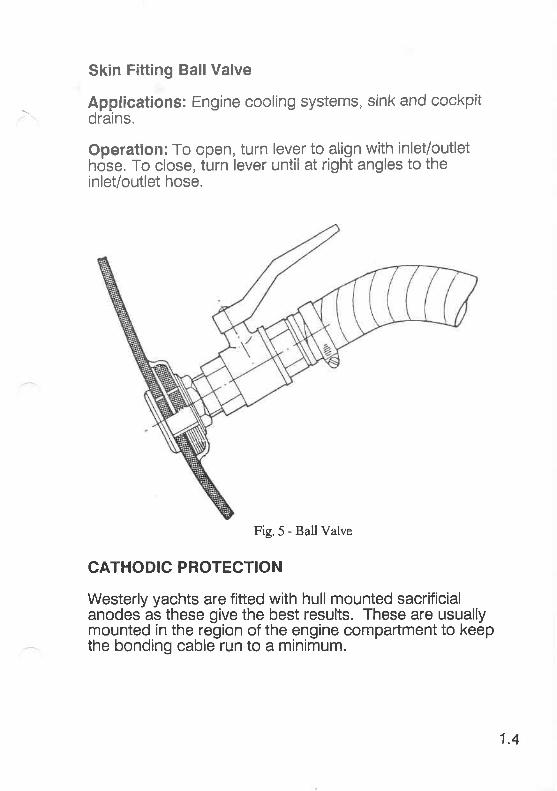
Skin Fitting Ball Valve
Applications: Engine cooling systems, sink and cockpitdrains.
Operation: To open, turn lever to align with inlet/outlethöse. To close, turn lever until at right angles to theinlet/outlet hose.
Fig.5-BallValve
CATHODIC PROTECTION
Westerly yachts are fitted with hull mounted sacrificialanodes as these give the best results. These are usuallymounted in the region of the engine compartment to keepthe bonding cable run to a minimum.
1.4
Attaehment
This is achieved by using 3/8" sttlds permahuilto which the bbnding eabie is securecjanode externally. The anode should be attand locking washers.
Bonding
Replacement
ANTIFOULING
From July 1987, allyachts are antifouled with Blakes TigerTin Free Antifouling.
1.5

l.:'$fi[[$::fiHD;:HlGSfl[$:;1 ;:;;:;,,:,;;1; ;,'- ; ;
TYPES OF RIG
STANDING RIGGINGShroud PlatesMaintenance ChecksRig AdjustmentAjustment of Fractional Rig
MAST VIBRATIONTheoryActions to Minimise Effect
SAILSResinated Sailcloth
.v Supercruise
FOLDING SAILSMainsailHeadsailsBaggingroläing
SETTING SAILSHoistingSheeting & TrimmingKicking StrapMainsail ReefingSpinnakers
2
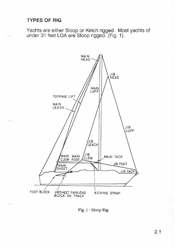
TYPES OF RIG
Yachts are either Sloop or Ketch rigged. Most yachts ofunder 31 feet LOA are Sloop rigged. (Fig. 1).
TOPPING LIFT
MA INLEA CH
FOOT BLOCK JIBSHEET FAIRLEAD KICKTNG 5TRAPBLOCK ON TRACX
2.1
MAIN TACKCLEW
Fig.1-SloopRig

The ditference between Sloop and Ketch rigged yachts isthe addition of a mizzen mast.
MIZZENHE AD
MrzLEAC H
MICLEW
FOOT BLOCK JIBSHEET FAIRLEAO KICKING STRAPBLOCK ON TRACK
2.2
MIZZENFOOT
FtS.z- Ketch Rig
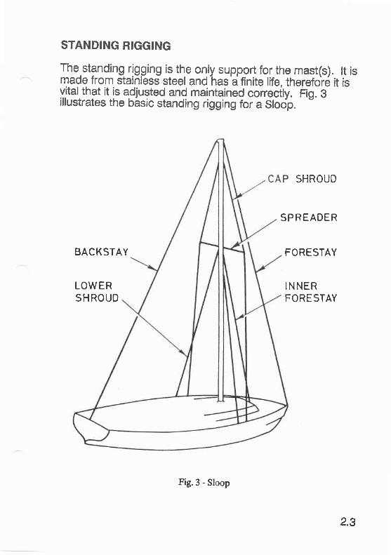
STANDING RIGGING
The.standing rigging is the only support for the mast(s). tt ismade from stainless steel and has a finite life, therefore it isvitalthat it is adjusted and maintained correcilv. Fio. Billustrates the basic standing rigging for a Sloop. -
BACKSTAY
LOWERSHROUO
SHROUD
SPREADER
FORESTAY
INNERFORESTAY
Fig.3 - Sloop
2.3

The Ketch rig has additional standing rigging for the mizzenmast (Fig.4).
JUMPER SHROIJD5
AFT MIZZENSHROUD
FORWARD MIZZENSHROUD
F g.4 - Ketch Rig
Shroud Plates
The standing rigging is attached to Shroud Plates,commonly called Chain Plates, located either side of themast at deck level. These are reinforced to withstand thetremendous pressure exefted by the sails. (Fig. 5 showsthe strengthening used).
2.4

Shroud ShroudAüatchment Attatchment
Plyarood Sandwich Through Deck Securementfor Chainplate andBracing EquiPment
Bolts securingTie Rod to Web
rrr-r_r,-S\-r!!l,lZQtfu y't1[ylTlVlirJtZzZtf f r_
Fig.5 - Shroud Plate
2.5
Maintenance Checks
Maintenance should be carried outMaintenance should be carried out regularly during theseason when the yacht is in commission and before anylong voyage. issioninq and Winterisation checks arecovered in the Wi section of thismanual.
1 Examine all steel wire rope for signs of corrosion, wearand damage.
2 Examine all terminations for signs of wear or damage. Payparticular attention at all split pins.
Note: Split pins should be a good llt through hole andshould not be underslzed.
4 Ensure the ends of the spreader bar are protected toprevent sail chafing.
5 Ensure the rig is.correctly adjusted. lf you are in anydoubt, you should consult the mast mänufacturers or arigging specialist.
Rig Adjustment
Mo-st.Westerly yachts have a Masthead Rig, adjustment isas follows:
1 Set up the mast with all rigging slack (see Fig. 6).
2 Tension the cap shrouds.
3 Tension the forestay and backstay.
2.6
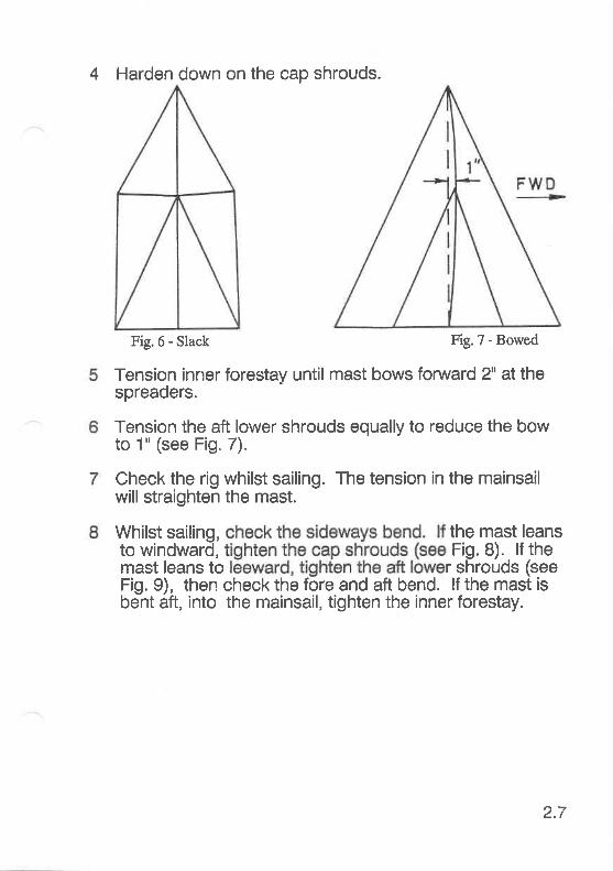
4 Harden down on the cap shrouds.
Fig.6 - Slack Fig.7 - Bowed
Tension inner forestay until mast bows forward 2" at thespreaders.
Tension the aft lower shrouds equally to reduce the bowto 1" (see Fig. 7).
Check the rig whilst sailing. The tension in the mainsailwill straighten the mast.
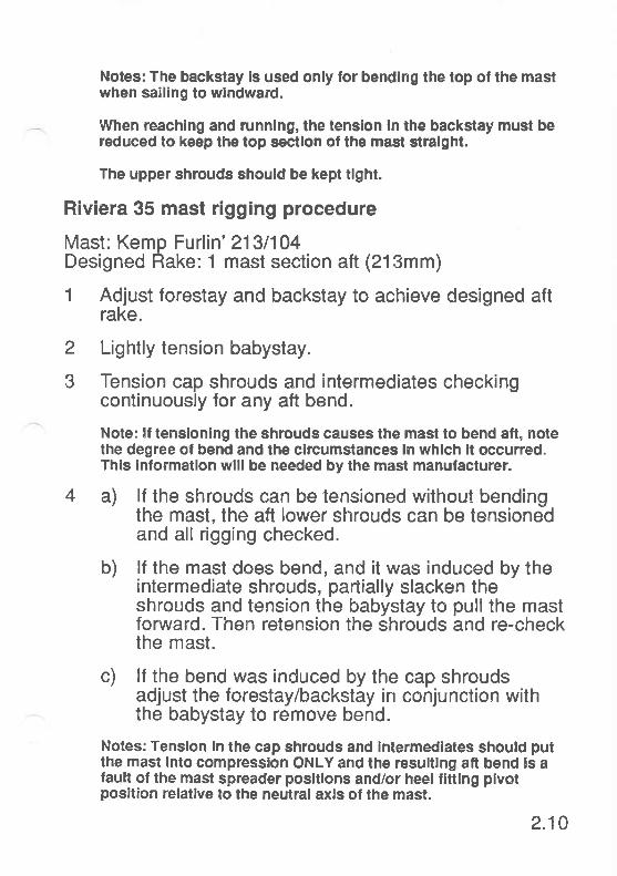
Whilst sailing, the mast leansto windward, Fig. 8). lf themast leans to r shrouds (seeFig. 9), then check the fore and aft bend. lf the mast isbent aft, into the mainsail, tighten the inner forestay.
Ftg.7 - Bowed
2.7
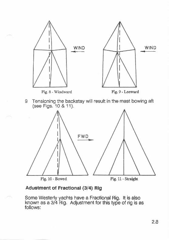
WIND+-
WIND
Fig.8 - Windward Fig.9 - I-eeward
9 Tensioning the backstay will result in the mast bowing aft(see Figs. 10 & 11).
Fig.9 - I-eeward
Fig.10 - Bowed Fig. 11- Straigbt
Adustment ol Fractlonal (3/a) Rig
Some Westerly yachts have a Fractional Rig. lt is alsoknown as a 3/4 Rig. Adjustment for this type of rig is asfollows:
2.8
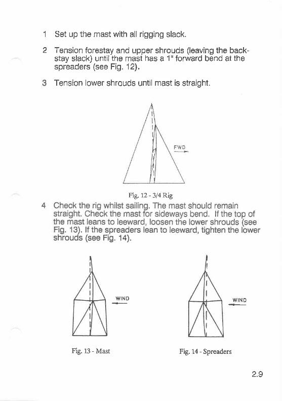
1
2
Set up the mast with all rigging slack.
Tension forestay and upper shrouds (leaving the back-stay slack) until the mast has a 1" forward bend at thespreaders (see Fig. 12).
Tension lower shrouds until mast is straight.
Ftg. LZ - 3/4 Rig
WIND WIND
2.9
Fig.l-3 - Mast Fig. 14 - Spreaders
Notes: The backstay ls used only for bendlng the top of the mastwhen salling to wlndward.
When reachlng and runnlng, the tenslon ln the backs{ay must bereduced to keep the top sectlon of the mast stralght.
The upper shrouds should be kept tlght.
Riviera 35 mast rigging procedure
Mast: Kemp Furlin' 213/104Designed Rake: 1 mast section atl (213mm)
1 Adjust forestay and backstay to achieve designed aftrake.
2 Lightly tension babystay.
3 Tension cap shrouds and intermediates checkingcontinuously for any aft bend.
Note: lf tenslonlng the shrouds causes the mast to bend aft, notethe degree ol bend and the clrcumstances ln whlch lt occurred.Thls lnformatlon wlll be needed by the mast manufacturer.
4 a) lf the shrouds can be tensioned without bendingthe mast, the aft lower shrouds can be tensionedand all rigging checked.
b) lf the mast does bend, and it was induced by theintermediate shrouds, partially slacken theshrouds and tension the babystay to pull the mastforward. Then retension the shrouds and re-checkthe mast.
c) lf the bend was induced by the cap shroudsadjust the forestay/backstay in conjunction withthe babystay to remove bend.
Notes: Tension ln the cap shrouds and Intermedlates should putthe mast lnto compresslon ONLY and the resultlng aft bend !s alault of the mast spreader posltlons and/or heel llttlng plvotposltion relatlve to the neutral axls ol the mast.
2.10
Problems encountered during rigging should be reportedso that the manufacturers can be lnformed.
During rlgging also check for any closing of the sall slot In the aftface of the masl, particularly in the vicinily of the sp!'eaders.
Working Aloft
MAST VIBRATION
srze.
Actions to Minimise Effect
1 Add additional inner wire forestay.
2 lncrease tension on the stays to decrease the naturalfrequency of the mast.
3 Use a 'Vortex Break'. This is a 4" strip of 9oz sailcloth,hoisted up the mast groove on the leeward side. Thisprevents the vortex turbulence from causing vibration.
2.104
4 lnternal mast halyards can magnify the noise of thevibration. This can be reduced by using internalpolyurethane foam'cushions'.
SAILS
Your Westerly yacht is supplied with Ratsey and Lapthornsails which, if treated with care and maintained correctly, willgive many seasons good service. Your sails will be madefrom either Vectis resinated sailcloth or Supercruise.
Resinated Sailcloth
This is the conventional sailcloth used and contains resinfillers. These sails must be folded to prevent the resin fillerfrom breaking up and causing permanent creases. Thesecreases distort the sail shape and make them viftuallyimpossible to set.
Supercruise
Supercruise does not contain any fillers, therefore stowseasily and remains crease-free. lt should however, still betreated with care.
WARNING: Do not smoke when working with sails.
Cigarette burns cause expensive damage to sails. lt isstrongly recommended that smoking is not allowed by anymember of the crew when handling sails.
FOLDING SAILS
Mainsail
One of the easiest methods of folding the mainsail is with itstill on the boom:
1 Tighten topping lift to support boom.
2.11
2
3
4
Lower the sail fully.
Ensure the coachroof is closed.
Ease the tension in the foot of the sail by releasing theclew outhaul.
Remove the battens to minimise stretch and chafing in thebatten pockets.
Stand close to the mast, on the opposite side of the boomto the pile of mainsail.
With an assistant at the leach, take hold of the sail abouttwelve inches from the boom, pull up together and lay thesail halfway over the boom. The bottom of the hangingfold should be approximately level with the bottom of theboom.
Take a further twelve inches of sail and fold back over theboom in the opposite direction.
Continue this 'layering' action untilthe entire sail is layedover the boom.
Secure the sail to the boom using sailties.
The halyard can either be removed and stowed or left at-tached to the head of the sail. lf left on the sail, secure tothe boom by passing a sail tie through the head of the sailand then tension the halyard.
lf the sail is to remain folded for more than a few hours,put the sail cover on to prevent damage from ultravioletlight or other source.
10
11
12
2.12
Headsails
lf your yacht is not fitted with a furling headsail, the headsailmust be removed and bagged when not in use. Dependingon the type of sail, it can be folded or'bagged' in the sailbag.
Bagging
1 Put the head of the sail into the sailbag first.
2 Work the luff and the leach in together, also the body ofthe sail.
3 Leave the tack and clew until last and pass the sailbagneck cord through both tack and clew before drawingtight.This method proves its worth in adverse conditions,enabling the tack to be connected to the stemhead andthe sheets to be fitted to the clew before the sail is releasedfrom the sailbag. The sheets can then be run back andsecured without being sail canalso be hanked to the e, untilonly the head is left to
Folding
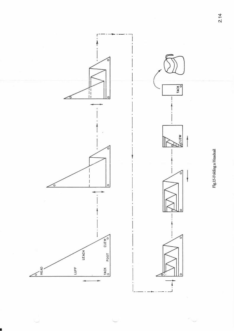
1 Lay the headsail out flat in a convenient position, a pon-toon or jeüy is ideal.
2 The sail should then be folded following the steps illustra-ted in Fig. 15.
SETTING SAILS
No. yacht will sail well if the sails are badly set. The fewpoints which follow are included to assisf in setting sailscorrectly.
2.13
r---+--.-
$
oi
I
t--_-l
Hoisting
the correct tension can be applied each time.
Sheeting and Trimming
The basic rule of sail sheeting is "Let it out 'til it flaps, pull itin 'til it stops."
The most common fault is sheeting in too hard. This is bestexplained in books specifically written for that purpose. lt isreöommended that every yacht's library has one.
Kicking Strap
This controls the amount of twist in the mainsail and alsoensures that the boom does not 'kick up'. The kickingstrap must always be tensioned, the only exception beingwhen the mainsail is sheeted in hard. The easiest way totension the kicking strap to the optimum position is by usingthe top batten as ä guide, This should be parallelto thebooml lf it lies to leäward, tighten the kicking strap, if it liesto windward, loosen it.
2.15
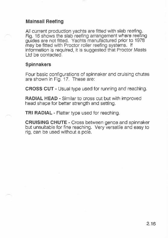
Mainsail Reefing
All c slab reefing.Fig. where reefinggulid prior to 1978may ems. lfinformation is required, it is suggested that Proctor MastsLtd be contacted.
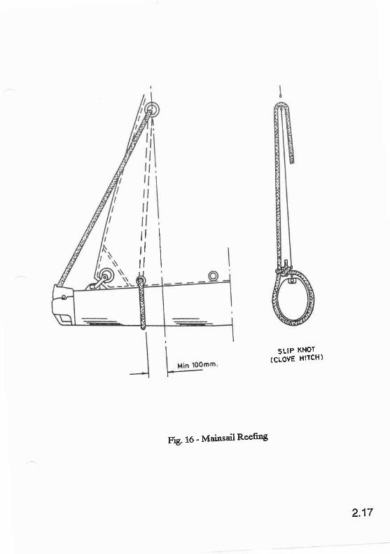
Spinnakers
Four basic configurations of spinnaker and cruising chutesare shown in Fig. 17. These are:
CROSS CUT - Usual type used for running and reaching.
RADIAL HEAD - Similar to cross cut but with improvedhead shape for better strength and setting.
TRI RADIAL - Flatter type used for reaching.
CRUISING CHUTE - Cross between genoa and spinnakerbut unsuitable for fine reaching. Very versatile and easy torig, can be used without a pole.
2.16
llllllrll
SLIP KNOT
(CLOVE HITCH)
Fig. 16 - Mainsail Reefi'g
2.17
CROSS CUT
TRI RADIAL
RAD IAL HEAD
CRUISING C H UTE
FLg. 17 - Spinn3l6e1.
2.18

HALYARO -
LUFF / LEACH
DOWNHAUL -,.
LEACH / LUFF
TOPPINGL IFT
Fig. 18 - TJpicat Spinnaker RiggingArrangement
2.19
HALYARD CLUTCHES
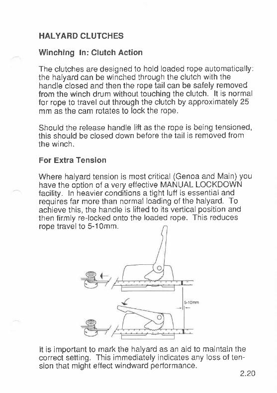
Winching ln: Clutch Action
The clutches are designed to hold loaded rope automatically:the halyard can be winched through the clutch with thehandle closed and then the rope tail can be safely removedfrom the winch drum without touching the clutch. lt is normalfor rope to travel out through the clutch by approximately 25mm as the cam rotates to lock the rope.
Should the release handle lift as the rope is being tensioned,this should be closed down before the tail is removed fromthe winch.
For Extra Tension
Where halyard tension is most critical (Genoa and Main) youhave the option of a very effective MANUAL LOCKDOWNfacility. ln heavier conditions a tight luff is essential andrequires far more than normal loading of the halyard. Toachieve this, the handle is lifted to its vertical position andthen firmly re-locked onto the loaded rope. This reducesrope travel to 5-1Omm.
It is important to mark the halyard as an aid to maintain thecorrect setting. This immediately indicates any loss of ten-sion that might effect windward performance.
2.ZO

New Rope
New halyards are slippery. lf the halyard slips when in the"CLUTCH" mode, use the MANUAL LOCK-DOWN facilityuntil the halyard has been worked in.
Release
ln normal wind conditions the load can be effoftlessly re-leased simply by lifting the handle without using the winch.ln heavier weather release is still possible this way - but forreasons of safety and rope care, rope should be re-tensionedon the winch drum before releasing the clutch. For safe re-lease, the handle should be moved into its fully-open positionso that the cam is lifted well clear of the moving rope.
After release the handle should be moved into its fully-openposition so that the cam is lifted well clear of the movingrope. After release the handle should be closed once more -
not left open to get in the way of the rigging or crew.
Warranty
ln the event that this product fails to perform satisfactorily forany reason, a rapid help and advice service is operated bythe manufacturer. Each clutch unit is covered by a two yearwarranty and any claim under this warranty should be madedirectly to Spinlock at the following address:
SPINLOCK CUSTOMER SERVICEOFFSHORE INSTRUMENTS LTD.41 BIRMINGHAM ROADCOWESISLE OF WIGHTPO31 7BHUNITED KINGDOM
TELEPHONE: (0) 983 295555
2.21
S. STEERI,NG,,'SVST'EMS
RUDDERSTransom Hung RudderSpade Hung Rudder
WHEEL STEERING SYSTEMSEdson Pedestal SteeringMaintenance
HYDRAULIC STEERINGUse with AutopilotHydraulic FluidFault FindingFurther lnformation
3
RUDDERS
Two main types of rudder are fitted, transom hung andspade hung.
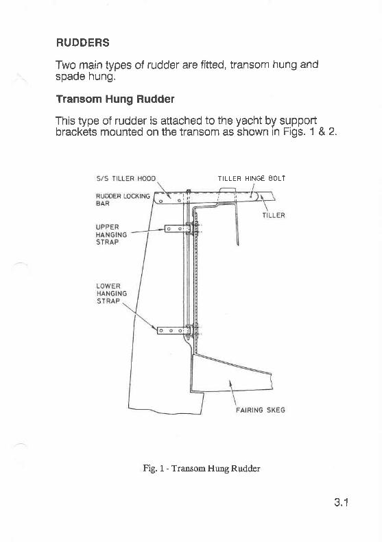
Transom Hung Rudder
This type of rudder is attached to the yacht by supportbrackets mounted on the transom as shown in Figs. 1 &2.
3.1
TILLER HINGE EOLT
Fig. 1 - Transom f{rrng Rudder
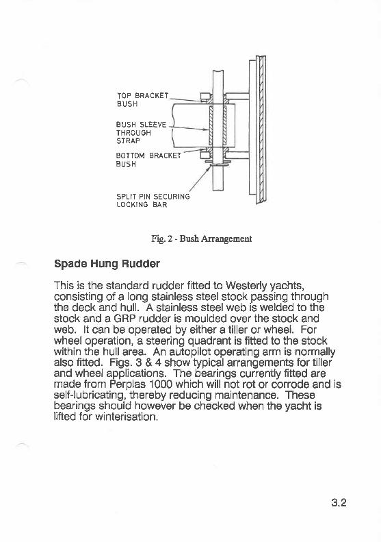
TOP BRACKETBUSH
BUSH SLEEVETHROUGHSTRAP
BOTTOM BRACKETBUSH
SPLIT PIN SECURINGLOCKING BAR
Fig.Z - gush Arrangement
Spade Hung Rudder
This is the standard rudder fitted to Westerly yachts,consisting of a long stainless steel stock passing throughthe deck and hull. A stainless steel web is welded to thestock and a GRP rudder is moulded over the stock andweb. lt can be operated by either a tiller or wheel. Forwheel operation, a steering quadrant is fitted to the stockwithin the hull area. An autopilot operating arm is normallyalso fitted. Figs. 3 & 4 show typical arrangements for tillerand wheel applications. The bearings currently fitted aremade from Perplas 1000 which will not rot or corrode and isself-lubricating, thereby reducing maintenance. Thesebearings should however be checked when the yacht islifted for winterisation.
3.2

1 - S/S Collar2 - S/S Bolt3 - Top Bush4 - Bottom Bush
lotRudde. Siocl
3.3
Fig. 3 - Tiller Steering Arrangement
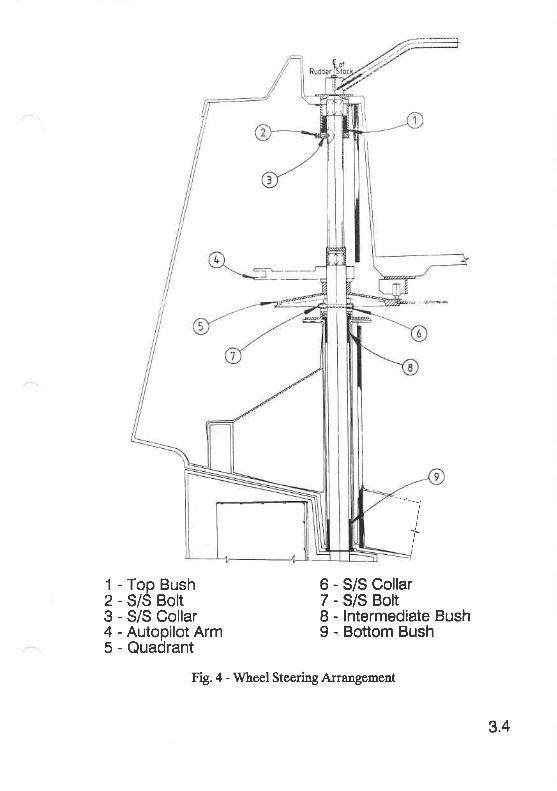
I1 - Top Bush2 - S/S Bolt3 - S/S Collar4 - Autopilot Arm5 - Quadrant
6 - S/S Collar7 - S/S Bolt8 - lntermediate Bush9 - Bottom Bush
3.4
Fig. 4 - Wheel Steering Arrangement

WHEEL STEERING SYSTEMS
The type currently fitted is manufactured by Edson. Someyachts were fitted with Whitlock systems and information onthese can be found in the Steering Systems section for OldModels.
Edson Pedestal Steering
Currently fitted is the double bowden cable type (Fig. 5).The cables are adjusted and tensioned at the quadrant.All cables should be checked and adjusted if necessaryafter the first 10 hours of use, and at regular intervalsthroughout the season.
Fig. 5 - Edson Steering System
3.5
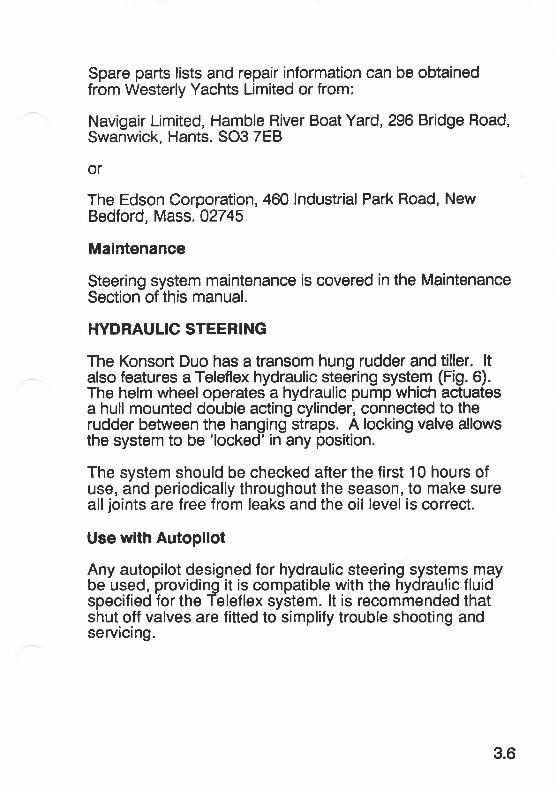
Spare parts lists and repair information can be obtainedfrom Westerly Yachts Limited or from:
Navigair Limited, Hamble River Boat Yard, 296 Bridge Road,Swanwick, Hants. SO3 7EB
or
The Edson Corporation, 460 lndustrial Park Road, NewBedford, Mass. 02745
Maintenance
Steering system maintenance is covered in the MaintenanceSection of this manual.
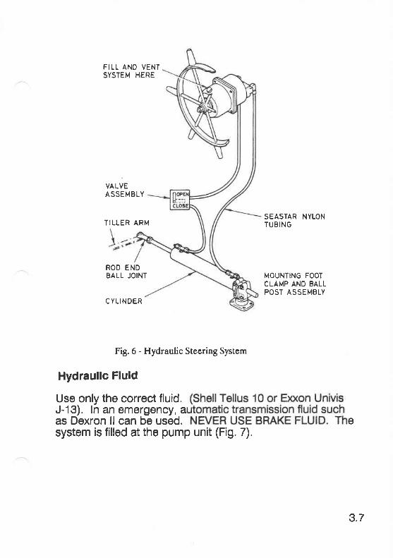
HYDRAULIC STEERING
The Konsort Duo has a transom hung rudder and tiller. ltalso features a Teleflex hydraulic steering system (Fig. 6).The helm wheel operates a hydraulic pump which actuatesa hull mounted double acting cylinder, connected to therudder between the hanging straps. A locking valve allowsthe system to be 'locked' in any position.
The system should be checked after the first 10 hours ofuse, and periodically throughout the season, to make sureall joints are free from leaks and the oil level is correct.
Use with Autopilot
Any autopilot designed for hydraulic steering systems maybe used, providing it is compatible with the hydraulic fluidspecified for the Teleflex system. lt is recommended thatshut off valves are fitted to simplify trouble shooting andservicing.
3.6
FILL ANO VENTSYSTEM HERE
VALVEASSEMBLY
SEASTAR NYLONTUBING
ROD ENDBALL JOINT MOUNTING FOOT
CLAMP AND BALLPOST ASSEMBLY
C YLI N DER
Fig. 6 - Hydraulic Steering Systcm
Hydraullc Fluld
Use only the correct fluid,J-13). ln an emergency, aas Dexron ll can be used. esystem is filled at the pump unit (Fig. 7).
TILLER ARM
3.7
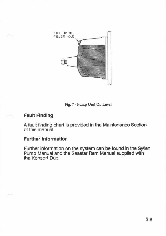
FILL UP TOFILLER HOLE
Fig.1 - Pump Unit Oil Lcvcl
Fault Flndlng
A fault finding chart is provided in the Maintenance Soctlonof this manual
Further lnlormatlon
Further information on the system can be found ln the SyllenPump Manual and the Seastar Ram Manual supplied withthe Konsort Duo.
3,8
-ENGINE SYSTEMS
FUEL SYSTEMSFuel TanksFuel StopcockFuel FilterReturn PipeFuel Contents
COOLING SYSTEMSSeawater Cooled EnginesFreshwater Cooled EnginesWater Filter
V EXHAUST SYSTEMS
ENGINE CONTROLSEngine Stop Mechanism
ENGI N E I NSTRU M ENTATION
BASIC ENGINE CAREMaintenanceToolsMaintenance Products
TURBOCHARGERSOperating InqtructionsMaintenance
4
4; [:[fQ:]fl f::::$S$frf,ffi$:
STERN GEARCutlass BearingCalcium DepositsShaft SealVentingVenting ProcedureLubrication

ENGINE SYSTEMS
The engines fitted to 1987 production yachts are Volvo 2000senes:
VOLVO 2OO2 - Griffon Club, Merlin, Konsort, Fulmar, Storm,Tempest
VOLVO 2003 - Konsort Duo, Seahawk, Falcon, Corsair
VOLVO 2003T - Corsair, Oceanlord, Sealord
Each yacht is supplied with the relevant manufacturersliterature for its engine. The following information istherefore of a general, rather than a specific, nature and issuperseded by any specific information given in themanufacturers literature.
FUEL SYSTEMS
The basic fuel system is illustrated in Fig. 1.
STOPC0CK
FEED I I NETURNII(OPTIONAL)Ir
FUEL FILTER rg
4.1
FILLER CAP
DIESELTANK
ENGINE
Fig 1- Basic Fuel System

Fuel Tanks
external finish, causing rust spots to develop.
Fuel Stopcock
on. lfrlock canm.
Fuel Filter
The bulkhead fuelfilter should be checked regularly forwater and drained or cleaned as necessary.
Return Pipe
On some engine installations there may be a return pipe tothe fuel tank from the engine fuel pump.
Fuel Contents
Fueltank contents are normally determined using a dipstick,but some yachts may be fitted with tud gauges.
Notes:
1 Keep the luel tank full whenever posslble as thlsprevents condensatlon lormlng ln the tank.
2 Aviod spillage ol fuel on the deck. Diesel on a deckcan be dangerous, it also attracts dlrt.
4.2
COOLING SYSTEMS
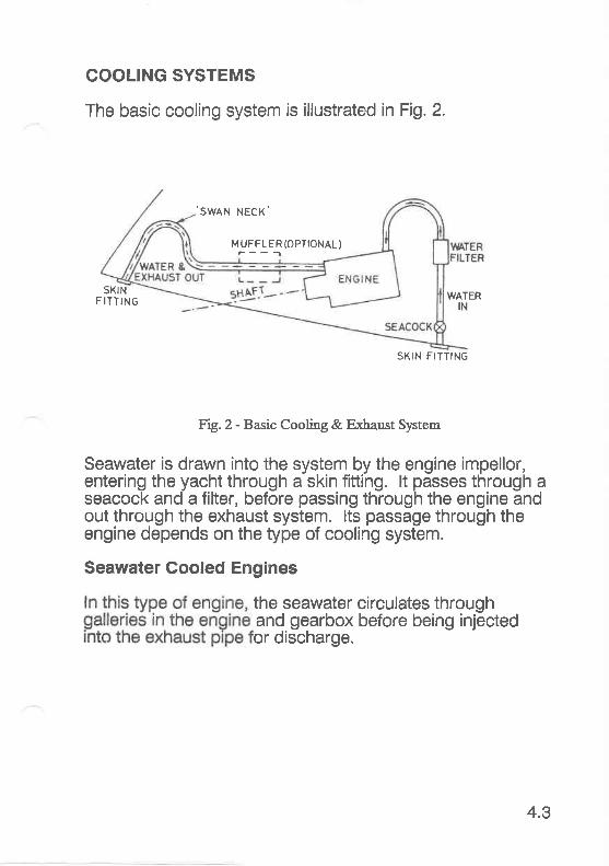
The basic cooling system is illustrated in Fig. 2.
.SWAN NECK'
MUFFLER (OPTIONAL)---f
SKINFITTING WATER
IN
frg.2- f,ss,is Qssling & Exhaust System
Seawater is drawn into the system by the engine impellor,entering the yacht through a skin fitting. lt passes through aseacock and a filter, before passing through the engine andout through the exhaust system. lts passage through theengine depends on the type of cooling system.
Seawater Gooled Engines
the seawater circulates throughand gearbox before being injectedor discharge.
SKIN FITTING
4.3
Freshwater Cooled Engines
uit.
system. The heated seawater is then injected into thoei<haust system for discharge. This typö of engine runs at aslightly higher temperature.
Water Filter
This basic strainer is a bulkhead mounted black cylinderapproximately 5" in diameter. For inspection, the capuhbcrews anfi-clockwise allowing access to the coarse wiremesh filter.
Notes:
1 Ensure cap ls not cross-threaded when replaced.
2 Ensure cap ls screwed down tightly to prevent airingress. This can cause damage to the impellor andthe engine il overheating occurs.
EXHAUST SYSTEMS
can further be avoided in two ways:
1 Close the inlet stopcock several seconds before stoppingthe engine.
2 After three or four attempts to start a stubborn engine,close the inlet stopcock untilthe engine starts.
4.4
WARNINGS:
1 DO NOT CRANK THE ENGINE OVER USING THEBATTERY WITHOUT CLOSING THE STOPGOCK. YOUMAY CREATE A HYDRAULIC LOCK AND CAUSEMAJOR DAMAGE TO THE ENGINE.
2 WHEN STARTING AN ENGINE, C}IECK THAT WATERIS BEING EJECTED THROUGH TNE EXHAUST WITHIN20 sEcoNDs. tF NoT, SWTTCH OFF AND |NVEST|GATE.FIRST CHECK THAT THE INLET STOPCOCK IS OPEN.
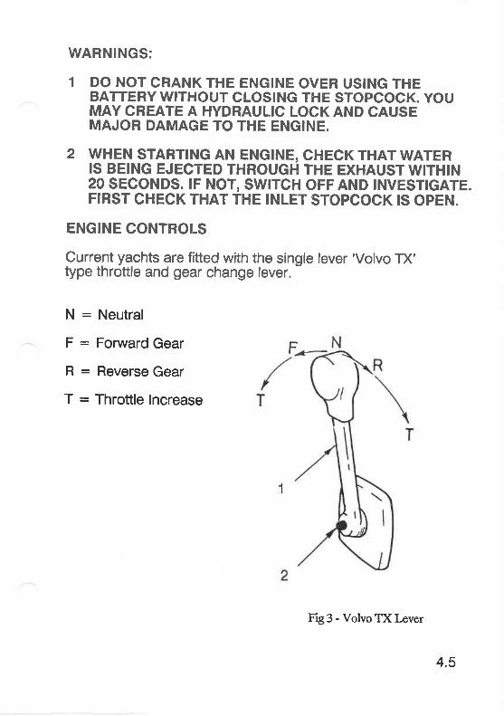
ENGINE CONTROLS
Current yachts are fitted with the single lever'Volvo TX'type throttle and gear change lever.
N = Neutral
F : Forward Gear
R : Reverse Gear
T = Throttle lncrease
Fig 3 - Volvo TX Lever
4.5
lever untilthe engine reaches the required revs.
Engine Stop Mechanism
Diesel engines are stopped by preventing the fuel beinginJected into the cylinders. This is normally achieved byusing a cable type control which is terminated with a control
Note: ll your englne lalls to start, when the batterles areln good condition, check llrst that the englne 'STOP'control is ln the'RUN' positlon.
ENGINE INSTRUMENTATION
This varies, depending on the type of engine fitted, but mostyachts are equipped with a rev counter, water temperaturegauge, oil pressure warning light and charging warning light.
BASIC ENGINE CARE
The.following basic points, if adhered to, will ensure longengine life. The most critical period is the first 20 - 30running hours.
1 Do not start an engine unless you are sure:
1.1Engine oil level is satisfactory.
l.2Gearbox oil level is satisfactory.
1.3 Goolant level is satisfactory (freshwater cooled enginesonly).
l.4Throttle set correctly - out of gear.
1.5 Fuel stopcock is open.
1,6 Fuel is free from contamination.
1.7Water inlet stopcock is turned on.
1.8 rt after one or two attempts,e engine over without turningSeek an approved engine
2 lmmediately after starting, check:
2.1 Oil pressure warning light erftinguished.
2.2Charging light extinguished (or ammeter reading satisfac-tory).
2.3Water emission from exhaust.
3 Avoid high revs.
4 Allow engine revs to decrease to idle before changinggear.
Do not allow engine to run at a low idle for long periods.
During runninE, check any instrumentation, ie. water tem-perature gauge,oil pressure warning light, etc.
Prjor to stopping engine, allow engine to idle for a fewminutes with the morse lever in neutral.
After.stopping engine, return 'STOP' control to the 'Run'posrtron.
5
b
4.7
I Ensure the first service is carried out by a manufacturer'srecommended agent,
10 Ensure all subsequent servicings are carried out at thecorrect frequency.
11 Ensure only the correct lubricants are used.
12 Adhere to all manufacturer's recommendations.
13 Keep an engine log. (See Maintenance Log).
Maintenance
Maintenance should be carried out in accordance with themanufacturers instructions. lf you do not feel capable ofundertaking any task, engage the services of a marineengineer.
Tools
The following tools are required to carry out basicmaintenance on Volvo 2000 series engines:
Combination Spanners - 8, 10, 13 & 17mm
Combination Spanner - 112" AF
8" Adjustable Spanner
Side Cutting Pliers
Flat Blade Screwdriver (7-1Omm blade width)
Cross Point Screwdriver (Phillips type)
Stainless Steel Knife
Hexagon Headed Wrenches - 5 & 1Omm (Allen Keys)
4.8

Oil Scavange Pump & Hose
For cylinder head tightening:
Torque Wrench capable of 70Nm (52 ft lbs)
17mm Socket to fit torque wrench
Malntenance Products
A table of recommended products for use with the Volvo2000 series engines is given in Table 1.
PRODUCT
Coolant type 85
Liquid gasket
SAE 2OW3Olubricating oil
lnhibiting oil
Grease
Propeller shaft grease
Engine pain
Universal oil
Rustproofing spray
voLvo Pt. No.
11415231141524
40879-1
1141502-31141506-41141515-5
1 141510-6
828250-1
1141509-8
837176-7837124-7
281404-4
1161038-3
SIZE
1 litre5litre
25 gm
1 litre5litre25 litre
1 litre
40 gm
500 gm
400 ml1 litre
165 ml
400 ml
4.9
Table 1 - Recommended Products
TURBOCHARGERS
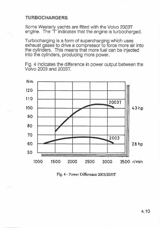
Some Westerly yachts are fitted with the Volvo 20037engine. The 'T' indicates that the engine is turbocharged.
Fig. 4 indicates the difference in power output between theVolvo 2003 and 2003T.
Nm
120
1r0
100
90
80
70
60
50
120037\.
.aa
.//
1 2003\
1000 r500 3000 3500 r/min
Fig.4 - Power DifferEnce 2M3|2AßT
zr3 hp
28 hp
4.10
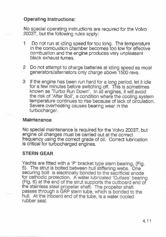
Operating lnstructions:
No special operating instructions are required for the Volvo2003T, but the following rules apply:
1 Do not run at idling speed for too long. The temperaturein the combustion chamber becomes too low for etfec'tivecombustion and the engine produces very unpleasantblack exhaust fumes.
2 Do not to charge batteries at idlinE speed as most'nators only charge above 1500 revs.
Severe overheating causes bearing wear in theturbocharger.
Maintenance
Volvo 2003T, buthe correctorrect lubrication
STERN GEAR
4.11

ol
+
J
LrJo
t!EU'
El!@@DE
FDE,Fv)Fl!Y(J
E,d)TL
tr,o
zG,UJFvlIE|9
19zztrl!Fol!G,FoGE,(9
aFJooFzUJ
(J
FF
kEoFc)
ct)I
\nobri
Fl!Lu)
EoJJlrJILoTEGvt(/l
oz._ß^- ulE=Fl..'t!(l-=Y!,sE0,3_!
okiov) z_
>=-o'1=-(L
ntitt
tndllrl
=ozUJlLllFtn o
z_
ElrJ@
otr,F(,E@lJ
e.lrJF
3
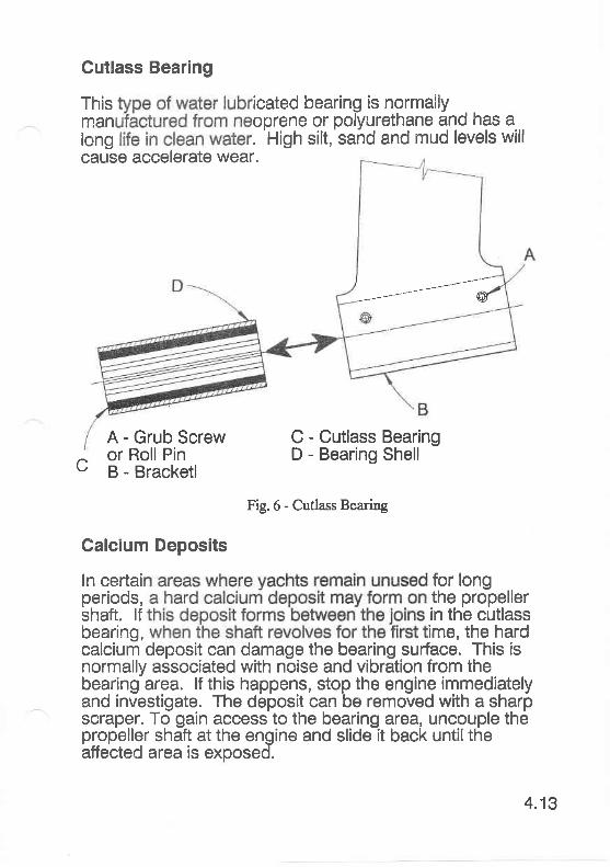
This icated bearing is normallyman oprene or polyurethane and has along . 'High silt,'sand and mud levels will
Cutlass Bearing
cause accelerate wear.
A - Grub Screwor Roll Pinc ä -'ääär<etr
G - Cutlass BearingD - Bearing Shell
Fig.6 - Cutlass Bearing
Calcium Deposits
ln certai for longperiods, the propellershaft. lf in the cutlassbearing, ime, the hardcalcium deposit can damage the bearing surface. This isnormally associated with noise and vibration from thebearing area. lf this happens, stop the engine immediatelyand investigate. The deposit can be removed with a sharpscraper. To gain access to the bearing area, uncouple thepropeller shaft at the engine and slide it back untiltheaffected area is exposed.
4.13
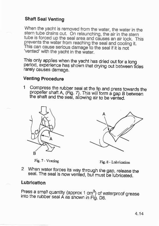
Shaft SealVenting
Ili::.lL.fqglig1y|.n the yacht has dried out for a tonspefloo, experience has shown that drying out between t"idesrarely causes damage.
Venting Procedure
1 compSess.the rubber seal at the lip and press towards thepropelter shaft.A, (Fig. 7). This wiil'foimägätB 6bl*eenthe shaft and the deal, allowing air to be väÄieO-.
---
Fig.1 - Venting Fig.8 - Lubrication
2 When water forces its way through the gap, rerease theseal. The sear is now venied, büt-musi 6äTüoriäatää.
Lubrication
'l'.,3',i3,'.i[f,|!l33ll'XJ3tgt1;;,;?lJgw€terproorsrease
4.14

Note: lt is recommended that Volvo Grease Pt No828250-1, or equivalent, is used.
2 The seal should be lubricated after approximately 200hours operation, or annually"
4.15

:5 r :,G AS:: gffiSf,flfl; ;:1:,
GAS SYSTEMMaintenanceLeaks
5
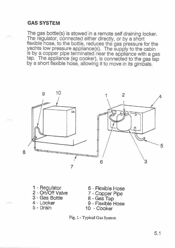
GAS SYSTEM
1 - Regulator2 - OnlOlf Valve3 - Gas Boüle4 - Locker5 - Drain
6 - Flexible Hose7 - Copper Pipe8 - Gas Tap9 - Flexible Hose
10 - Cooker
Fig. 1- Tlpical Gas System
5.1
Maintenance
Maintained correctly, gas systems are safe and trouble free.At the start of each season and before any long voyage, thefollowing checks are recommended:
1 All rigid pipes and fittings should be checked for corrosion.
2 Allflexible pipes should be checked for perishing.
Note: lt is recommended that all flexlble hoses arereplaced annually.
3 All gas taps and controls should be tested for operation.
4 Gas bottle lockers should be cleaned thoroughly anddrains checked for blockages.
5 Regulators should be examined for corrosion or damage.lf in doubt - do not attempt to repair a regulator - take it toyour nearest gas stockist.
Leaks
WARNING: DO NOT TEST FOR LEAKS W|TH A NAKEDFLAME.
5.2
,6,,,,,,WATERÄ/VASif E-,,$V,'$TE[11[:,:,:,,:,:,: :,,,:,:,: : :,:, :,
EQUIPMENT CHART
WATER SYSTEMS
WASTE SYSTEMS
TOILETS
BRYDON MARINE TOILETOperating I nstructionsWinterisation ProcedureSpare Parts
BRYDON TOILET WITH HOLDING TANK
6
WESTERLY YACHT WATER/WASTE EQUIPMENT CHART
CURRENT PRODUCTION YACHTS
YACHT
KONSORT
KOI.ISORT DUO
TANK PRESSURECAPACIW SYSTEM +
(Galls) HOT WATER
30 NO
1OO YES
TEMPEST 30
FULMAR 30
STORM 40
STORM CRUISING 40
RIVIERA
SEAHAWK
FALCON
CORSAIR
OCEANLORD
NO
NO
NO
YES
YES
60 YES
65 YES
70 YES
1 10 YES
GALLEYPUMP OHBACK-UP
FOOT PUMP
FOOT PUMPBACK-UP
HAND PUMP
FOOT PUMP
FOOT PUMP
FOOT PUMPBACK-UP
F@T PUMPBACK.UP
FOOT PUMPBACK-UP
FOOT PUMPBACK-UP
F@T PUMPBACK-UP
FOOT PUMPBACK-UP
HEADS
WC BASIN/SHOWER
BRYDON HAND PUMP
BRYDON COMBINED TAP/SHOWER HEAD
BRYDON HAND PUMP
BRYDON FOOT PUMP
BRYDON FOOT PUMP
BRYDON COMBINED TAP/SHOWER HEAD
BRYDON COMBINED TAP/SHOWER HEAD
BRYDON COMBINED TAP/SHOWER HEAD
BRYDON COMBINED TAP/SHOWER HEAD
BRYDON COMBINED TAP/SHOWER HEAD
BRYDON COMBINED TAP/SHOWER HEAD
ADDITIONAL HEADS
WC BASIN SHOWER
HaC
BRYDON H & C
BRYDON H & C
BRYDON COMBINED TAP/SHOWER HEAD
40
Note: The Oceanlord is fitted with pumped shower drains.
6.1
cr)d
;L.o
Q*JE3E!€F -z..P. o- q.l
E+=J_l/'l O
Erco-oa-oot-o(Ucn
A
o
.cuoJd.(ut-
>tIr I IJJf=(-., o
LJ
Ec)v(t)
ctN,'üI
_aU€Fo
bbIE
+aoO-tr.l
EJ_ o(J
H>
Lö+a=E=LJLJ
o-E
. J
Eo-o
LL
3-+(I,
t!
<
o.e=d_
>r llll>
Notes:
1 The valve lever should be left in the'DRY BowL'position when the toilet is not in use.
2 Always close the inlet and outlet seacocks when theyacht is to be left unattended.
Wlnterisation Procedure
1 Remove drain plug in base of toilet.
2 Ensure valve lever is in 'DRY BOWL' position.
3 Operate pump.
Notes:
1 ln salt water areas,llushing wlth fresh water ls recom -mended.
2 Do not use antlfreeze, aclds, harsh alkalls,lavex orhousehold bleach.
3 After a long period of non-use, it is recommended thatthe inner surface of the pump cylinder ls lightlycoated with vaseline.
Spare Parts
Toilets are supplied with an illustrated parts list with UK andUS contact addresses. Any Brydon, Par or Jabscodistributer should stock spare parts.
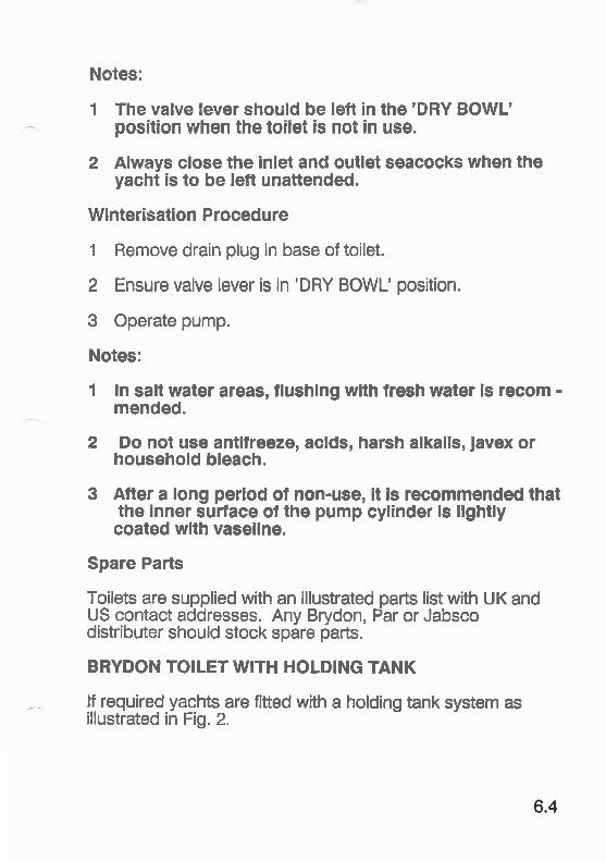
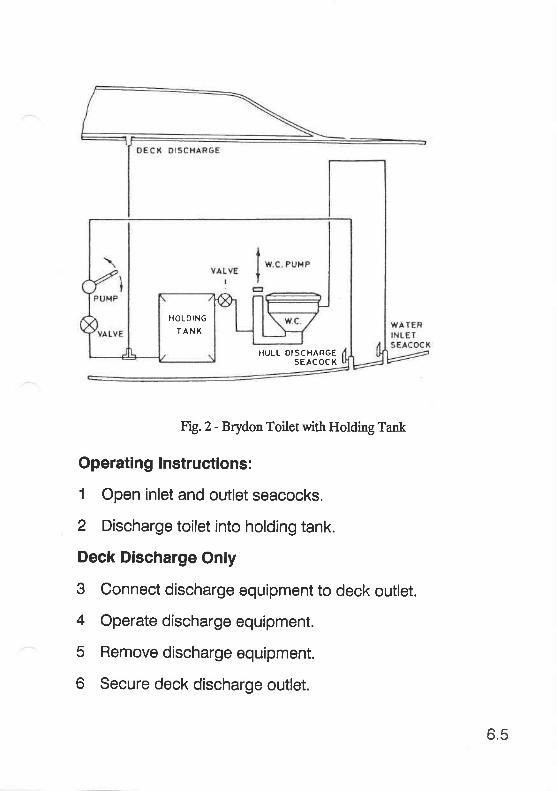
BRYDON TOILET WITH HOLDING TANK
lf required yachts are fitted with a holding tank system asillustrated in Fig. 2.
6.4
HOLOING
TÄNX
HULL DISCHARGESEAC OC K
Fig.Z - Brydon Toilet with Holding Tank
Operatlng lnstructions:
1 Open inlet and outlet seacocks.
2 Discharge toilet into holding tank.
Deck Dlscharge Only
3 Connect discharge equipment to deck outlet.
4 Operate discharge equipment.
5 Remove discharge equipment.
6 Secure deck discharge outlet.
6.5

Hull Discharge Only
3 Pump out waste.
4 Close hull inlet seacock.
5 Close inlet seacock.
6.6

BASIC ELECTRICAL SYSTEM
BATTERIES
BATTERY ISOLATION SWITCHES
SWITCH PANELS
POWERCENTRESwitchesDC Circuit BreakersBattery ConditionUse of the SystemEngine BatteryBattery ChargingSingle Battery OperationMains Powered Battery Charging
IYS SWITCH PANEL
7
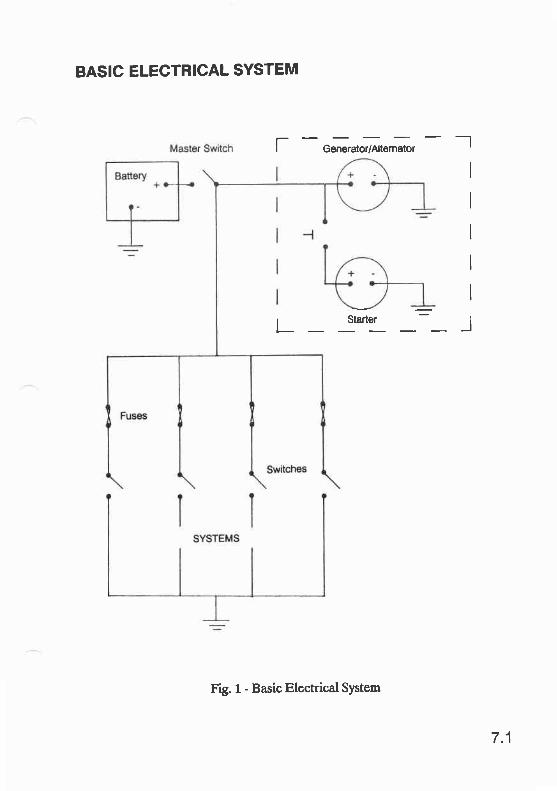
BASIC ELECTRICAL SYSTEM
[ -O"n"r"tortltt"r*, - _l
I
r Starler :r-l
F g. 1 - Basic Electrical System
7.1
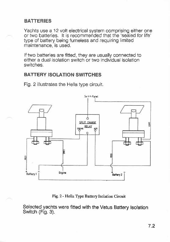
BATTERIES
Yachts use a 12 volt electrical system comprising either oneor two batteries. lt is recomrnended that the 'sealed for life'type of battery being fumeless and requiring limitedmaintenance, is used.
lf two batteries are fitted, they are usually connected toeither a dual isolation switch rr two individual isolationswitches.
BATTERY ISOLATION SWITCHES
Fig. 2 illustrates the Hella type circuit.
Fig.2 - Hella Type Battery Isolation Circuit
Selected yachts were fitted with the Vetus Battery lsolationSwitch (Fig.3).
7.2
Swi lrh Panel

Fig. 3 - Vetus Isolation Switch
This type of isolation switch allows both batteries to beconnected in parallel for engine stafting. lf your yacht isfitted with this type of switch and has two batteries fitted, thefollowing points should be noted:
1 Always switch off batteries when not required and not oncharge.
2 Use on e and one for auxiliary use.When t es flat, do not switch io theengine ine, using the engine battery,and full
7.3
3 Try to keep the auxiliary battery fully charged, this willen-able it to be used to staft the engine if the enginebattery is flat.
SWITCH PANELS
Two types of switch panel are currently fitted, the'Powercentre' and the'lYS'.
POWERCENTRE
This comprises circuit switches with illuminated displays,circuit breakers and a battery status display.
Switches
These control the output of the battery circuit to the varioussystems. The switch legend, to the right of the switch, lightswhen the circuit is switched on.
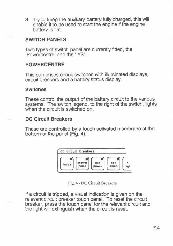
DC Circuit Breakers
These are controlled by a touch activated membrane at thebottom of the panel (Fig. 4).
Fig.4 - DC Circuit Breakers
lf a circuit is tripped, a visual indication is given on therelevant circuit breaker touch panel. To reset the circuitbreaker, press the touch panel for the relevant circuit andthe light will extinguish when the circuit is reset.
7.4
@@@@E
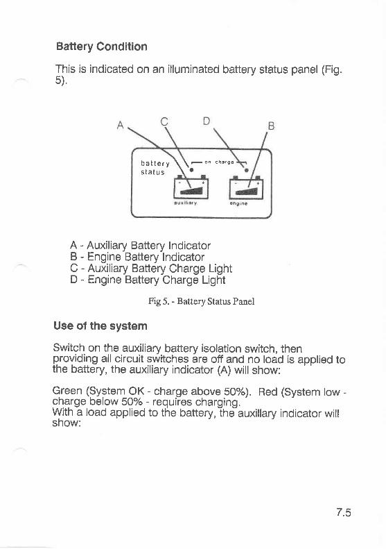
Battery Condition
This is indicated on an illuminated battery status panel5).
(Fis.
A - Auxiliary Battery lndicatorB - Engine Battery lndicatorC - Auxiliary Battery Charge LightD - Engine Battery Charge Light
Fig 5. - Battery Status Panel
Use of the system
Switch on the auxiliary battery isolation switch, thenproviding all circuit switches are off and no load is applied tothe battery, the auxiliary indicator (A) will show:
Green (9ygtenl QK - eharge above 5Oo/o). Red (System tow -gharge below 50% - requiies charging.With a load applied to the battery, the auxillary indicator willshow:
battery \\-on charee
status \ '
t.c

Green (System OK - charge above 50%). Yellow (Ghargebe . Red (Chargebe ed (Flashing) -(C recharge now).
Note: lf load is removed when indicator is yellow, it willrevert to green. Red and red (flashing) will remaln onuntil battery ls recharged.
Engine Battery
Switch on the engine battery isolation switch, engineindicator (B) will show:
lf 'Off Load':
Green (System OK - charge above 60%). Yellow (caution -Charge between 50% and 60% - recharge battery). Red(danger - Charge below 50% - recharge battery urgently).
Note: When starting the engine, the display will changeto red.
Battery Gharging
When the engine is running, the generator/alternator wiilcharge the system as follows:
1 Engine on charge indicator (D) will light.
2 Auxiliary on charge indicator (C) will light when the splitcharge relay engages.
3 Auxiliary and I light. Thisindicates the harge level. Runengine for 2 harge level.
7.6
Note: When the englne ls switched off, the yellowcharging indicators (C & D) will rematn on forapproximately 2 mlnutes and the spllt charge relay wllldlsengage.
Slngle Battery Operation
1 Battery level indicated on engine display (B).
2 On charge light (D) will indicate battery is on charge.
3 Engine display is green when the minimum charge level isreached.
4 The auxiliary display (A) is red when lights etc. are usedwithout the engine running.
Malne Powered Battery Charglng
A mains powered battery charger is available for use withthe Powercentre. Further ir formation is available from:Kdd Powercentre Limited, Tregoniggie lnd Est, FALMOUTH,Cornwall. TR11 4SN.
7.7

NS SWITCH PANEL
1
234567I910111213141516171819
Aft GabinSaloonFwd CabinDeckComPassShowerWaterNavigation9 nstsAux 4Aux 3Aux 2AnchorStrigNav 2NavlNegativeAux 1
Positive
7.8

I
HULL
Keel BoltsDectectionRepair a Leaking Keel BoltSkin Fittings & SeacocksSacrificial AnodesAntifouling
SAILS & RIGGINGSailsRopes
STEERING SYSTEMSRudders
v Wheel Steering SystemsHydraulic Steering Fault Finding
ENGINE SYSTEMSFault FindingMaintenanceStern Gear
GAS SYSTEMMaintenanceLeaks
WATERAA/ASTE SYSTEMSBrydon ToiletLavac ToiletSL /+00 Toilet
WI NTERISATION/DEWI NTERISATION
CLEANING
HUI.L
Keel Bolts
Despite being fully sealed and bonded at the time ofmanufacture, the hull/keel joint is a primary target for leaks.Running aground or standing on bilge keels will increase therisk.
CAUTION: The following informatlon is provided toassist suitable experienced mar!ne engineers andassumes that suitable equipment and conditions areavailable to carry out the repair procedures.
Westerly Yachts Limited cannot be held responsible lorany damage incurred using the procedures.
Detection
A leaking keel bolt, will nearly always produce rust staining.This is a result of staining from the keel sudace and not from
ng bolts normallyaking occurs onlya major structurala leak is
suspected but no there is no sign of staining, the followingprocedure should be adopted:
1 Dry the suspected area thoroughly.
2 Place a ring of 'plasticine', or similar, around thesuspected bolt(s).
3 Check the area for signs of water within the ring. lf waterbecomes trapped in the area, it is likely there is a leak.
Repairing a Leaking Keel Bolt
Leaking keel bolts must be tackled one at a time. Requiredtools and materials are as follows:
8.1
1 A suitably sized socket or spanner:
1978 to date - Metric1975 to 1978 - Whitworth or MetricPre 1975 - Whitworlh
2 A scraper.
3 Rag or other drying medium.
4 Caulking cotton.
5 Thiosulphide sealant (Keelbond or Thiofix etc.).
The following procedure is carried out from inside the hull.
1 Having identified the relevant bolt, remove the protectivegelcoat.
2 Undo the locknut, using the correct sized socket orspanner (Fig. 1).
3 Remove the nut and small washer.
4 Remove the plate washer and clean ready for reassembly.Seepage will occur if the yacht is in the water.
5 Throughly dry the area using a suitable material.
6 Make up a ringlet of caulking cotton as shown in Fig. 2.
8.2
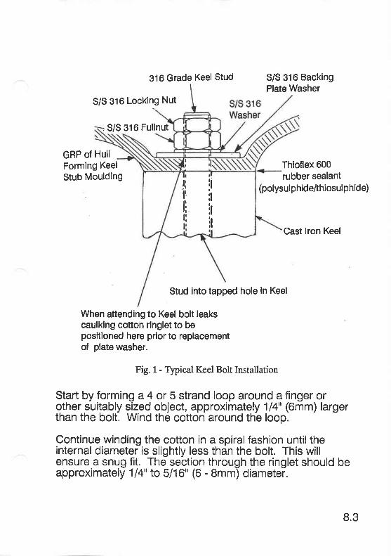
316 Grade Keel Stud S/S 316 BackingPlate Washer
S/S 316 Locklng Nut
, S/S 316 FullnutN
GRP of HullFormlng Keel
Stub MouldingThioflex 600rubber sealant
(polysul phideithiosul phide)
Cast lron Keel
Stud into tapped hole ln Keel
When attending to Keel bolt leakscaulklng cotton rlnglet to beposftloned here prlor to replacementof plate washer.
Fig. 1- Typical Keel Bolt Installation
Start by forming a 4 ü 5 strand loop around a finger orother suitably sized object, approximately 114" (6mm) largerthan the bolt. Wind the cotton around the loop.
Continue winding the cotton in a spiralfashion untiltheinternal diameter is slightly less than the bolt. This willensure a snug fit. The section through the ringlet should beapproximately '1l4" to 5716" (6 - 8mm) diameter.
lt:l
irlt
lil!
tili
8.3
7
I
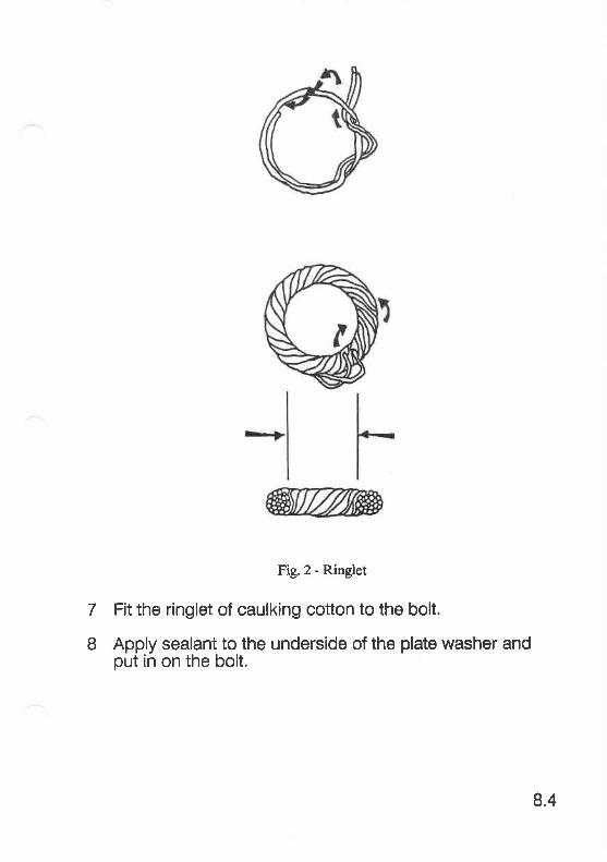
Fig.2- ftinglet
Fit the ringlet of caulking cotton to the bolt.
Apply sealant to the underside of the plate washer andput in on the bolt.
8.4
I Fit the plain washer and nut. Tighten the nut. WesterlyYachts Ltd do not use a torque setting for tightening keelbolts, but as a guide, 24mm bolts should be tightedto 150ft lbs, 20mm bolts to 85ft lbs and 1Smm bolts to55ft lbs.
10 Fit and tighten the locknut to 30% of the torque figurerequired for the full nut.
11 When the sealant has cured, coat the whole assemblywith gelcoat. Resin or paint will suffice if gelcoat is notavailable. This will both seal and lock the threads.
12 Regularly inspect the repaired area for signs of leaks untilsatisfied that the repair is totally watertight.
Skin Fittings & Seacocks
Gate Valves
Check regularly:
1 Free operation of valve.
2 Security and condition of hose and hose clip.
lf valve is jammed or fails to operate correctly, it should bereplaced.
Sleeve Valve
Check regularly:
1 Free operation of valve.
2 Seal between body and core.
3 Security and condition of hose and hose clip.
8.5
lf valve is stiff:
1 Remove core from body.
2 Clean, regrease and replace.
lf valve is leaking:
Check security of bolts, tighten as necessary.
Ball Valve
Check regularly:
1 Free operation of valve.
2 Security and condition of hose and hose clip.
8.6
Skin Fitting Gate Valve with Strainer
This type is fitted to some early yachts (Pre 1982).
Check regularly:
1 Free operation of valve.
2 Cleanliness of strainer.
3 Security and condition of hose and hose clip.
4 Cathodic bonding if applicable.
lf valve is jammed or fails to operate correctly, it should bereplaced.
Fig4-GateValve.
:
8.7

Sacrif!cial Anodes
These must be checked annually. lf the yacht is not liftedand winterised the anode can be checked by hand from adinghy. lf this is not possible, allowing the yacht to 'dry out'on soft mud will enable it to be checked between tides. SeeHull section for fufther information.
Antifouling
This should be checked annually. lf the yacht is not lifted,allow the yacht to 'dry out' on soft mud between tides toprovide an opportunity for inspection.
SAILS AND RIGGING
Rigging checks and adjustments are detailed in the Sailsand Rigging section.
Sails
Sails should be checked regularly during the season for thefollowing:
1 Chaffing (Mainly at spreaders and on foot of large sails).
2 Tears at batten pockets and all attachment points, Tack,Clew, Head, Hails and Reefing Gringles.
3 Other damage.
Ropes
All ropes should be checked regularly during the season forthe following:
1 Damage to whipping or heat shrink sleeves.
8.8
2 Signs of wear or damage where constantly cleated,clamped, passed round sheave blocks or throughfairleads.
3 Splices are serviceable. This is particularly importantwhere nylon ropes are spliced to steel wire ropes, suchas halyards.
STEERING SYSTEMS
Rudders
Rudders become less efficient as bush wear increases.Bushes should therefore be checked at the end of eachseason and repaired as necessary. See Steering Systemssection for typical bush arrangement.
WhEel Steerlng Systems
ld only be carried out if in
53ä,1'J ItE # 3x"Jr:l?." avai I ab I e
Lubrication of the cables and quadrant should be carriedout annually. On extended voyages, it is recommended thatlubrication is carried out weekly.
Whltlock. See Pre 1988 Section for information on Cobra,Mamba and Titan systems.
Hydraulic Steering Fault Flnding
Note: Sometlmes when returning the wheel lromhard-over, a slight reslstance may be felt and a cllckingnoise heard. Do not mlstake this lor a fault.
FAULT 1 - Steering stitf (even when craft is not moving).
PROBABLE CAUSE - Mechanical binding at rudder,bushes/bearings binding.
8.9
ACTIOi{ - Disconnect ram from tiller arm and check. lf stillstiff, check for restriction in hose, repair as necessary. lf nohose retriction, check viscosity of fluid. Drain and reiill asnecessary.
FAULT 2 - Rudder drifts when underway.
PROBABLE CAUSE - Dirt in system.
ACTION - Drain, flush and refill, then recheck.
FAULT3-Leakingseals.
ACTION - Replace seals or unit.
8.10
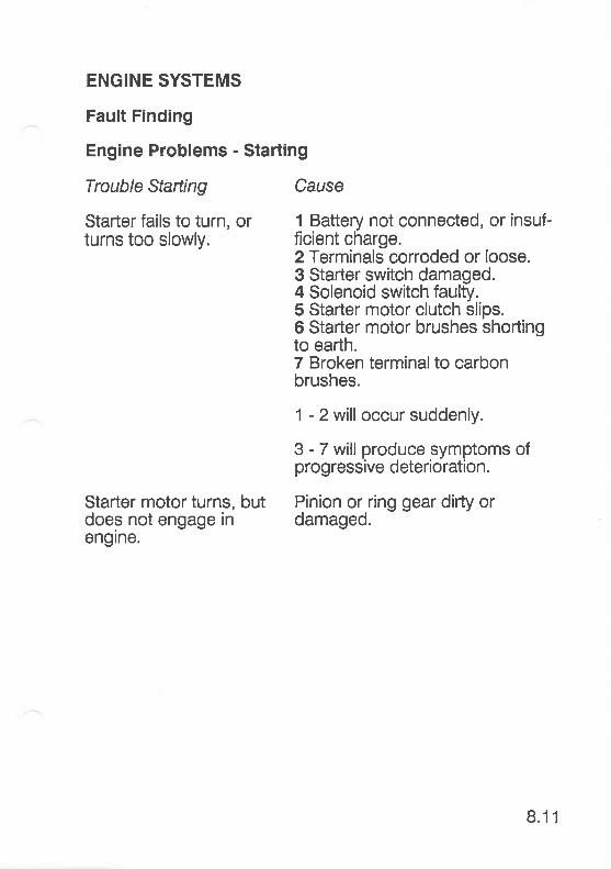
ENGINE SYSTEMS
Fault Finding
Engine Problems - Starting
Trouble Starting Cause
Starter fails to turn, or 1 Battery not connected, or insuf-turns too slowly. ficient charge.
2 Terminals corroded or loose.3 Starter switch damaged.4 Solenoid switch faulty.5 Starter motor clutch slips.6 Starter motor brushes shortingto earth.7 Broken terminalto carbonbrushes.
1 - 2 will occur suddenly.
3 - 7 will produce symptoms ofprogressive deterioration.
Starter motor turns, but Pinion or ring gear difty ordoes not engage in damaged.engrne.
8.11
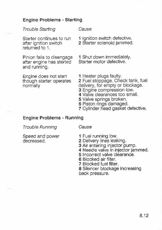
Engine Problems - Starting
Trouble Starting Cause
Starter continues to run 1 lgnition switch defective.after ignition switch 2 Starter solenoid jammed.returned to 1.
Pinion fails to disengage 1 Shut down immediately.after engine has starled Starter motor defective.and running.
Engine does not staft 1
though starter operates 2normally d
34V5
? äefective.
Engine Problems - Running
Trouble Running Cause
Speed and power l Fuel running low.decreased. 2 Delivery lines leaking.
3 Air entering injector pump.4 Needle valve in injector jammed.5 lncorrect valve clearance.6 Blocked air filter.7 Blocked fuelfilter.8 Silencer blockage increasingback pressure.
8.12
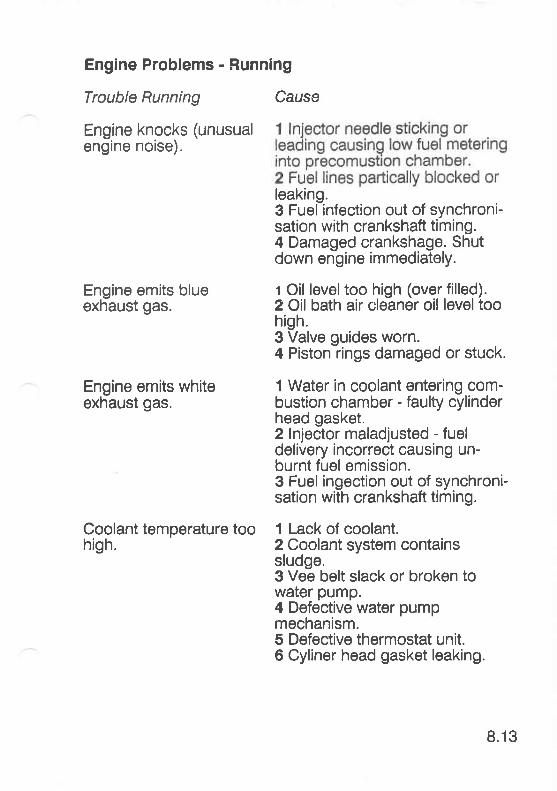
Engine Problems - Runnlng
Trouble Running
Engine knocks (unusualengine noise).
Engine emits blueexhaust gas.
Engine emits whiteexhaust gas.
Coolant temperature toohigh.
Cause
leaking.3 Fuel infection out of synchroni-sation with crankshaft timing.4 Damaged crankshage. Shutdown engine immediately.
t Oil level too high (over filled).2 Oil bath air cleaner oil leveltoohigh.3 Valve guides worn.4 Piston rings damaged or stuck.
1 Water in coolant entering com-bustion chamber - faulty cylinderhead gasket.2 lnjector maladjusted - fueldelivery incorrecl causing un-burnt fuel emission.3 Fuel ingection out of synchroni-sation with crankshaft timing.
1 Lack of coolant.2 Coolant system containssludge.3 Vee belt slack or broken towater pump.4 Defective water pumpmechanism.5 Defective thermostat unit.6 Cyliner head gasket leaking.
8.13
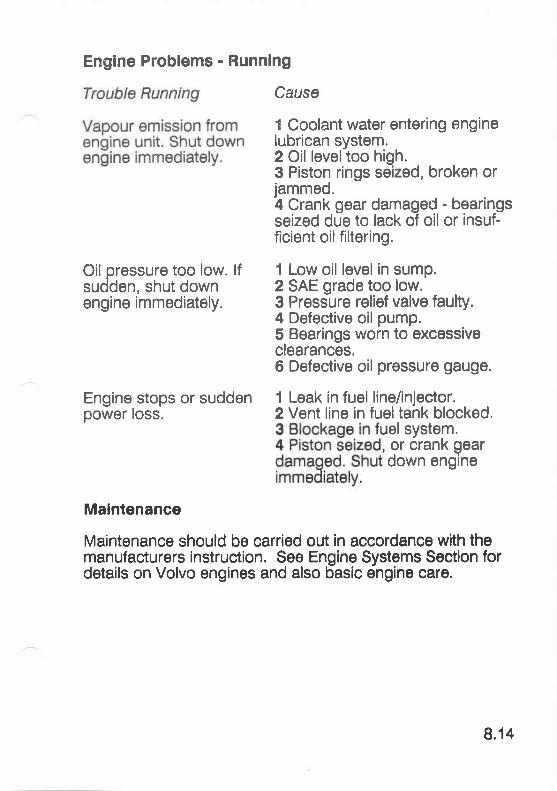
Oil oressure too low. lfsudden, shut downengine immediately.
Engine stops or suddenpower loss.
Englne Problems - Runnlng
Causa
1 Coolant water entering enginelubrican system.2 Oil leveltoo high.3 Piston rings seized, broken orjammed.4 Crank gear damaged - bearingsseized due to lack of oil or insuf-ficient oilfiltering.
1 Low oil level in sump.2 SAE grade too low.3 Pressure relief valve faulty.4 Defective oil pump.5 Bearings worn to excessiveclearances.6 Defective oil pressure gauge.
1 Leak in fuel line/injector.2 Vent line in fueltank blocked,
el system.or crank qeardown engine
Malntenance
Maintenance should be carried out in accordance with themanufacturers instruclion. See Engine Systems Sec'tion fordetails on Volvo engines and also basic engine care.
8.14
Stern Gear
Calcium Deposits - see Engine Systems Section.
Shaft Seal Venting - see Engine Systems Section.
Shaft Seal Lubrication - see Engine Systems Section.
GAS SYSTEM
Maintenance - see Gas Systems Section.
Leaks - see Gas Systems Section.
WATER/WASTE SVSTEMS
Brydon Toilet
Winterisation - see WaterMaste System Section.
Spare Parts - see Water/Waste System Section.
Lavac Toilet
Maintenance - see WaterMaste System Old Models Section.
Winterisation - see WaterMaste System Old Models Section.
SL 400 Toilet
Spare Parts - see WaterMaste System - Old Models Section.
WINTERISATION/DEWI NTERISATION
Westerly Yachts recommends that all vessels are taken outof the water every year. All plastics absorb moisture whenimmersed in water. lf you wish to keep your vessel in topcondition, it should be allc wed to dry out.
8.15
I.AYING UP CHECKLIST
1 lf hauled out and propped up, check:
Security of props and shores
Wedges between shores and topsides
Stakes to stop lower ends moving
Secure fore and aft (top and bottom)
Prop under forefoot
ls it safe against likely wind directions and vandals?
2 Gheck insurance covers layed up period.
3 Ensure adequate ventilation while leaving boat.
4 Consider heating. I r bars onlateral wood struls joinery etc.,if the boat is afloat ral heating
by thermostat or time control or both.
5 Remove cushions for cleaning and storage.
6 Prop open all locker doors and hatches to air.
7 Take home everything likely to rust - pans, old galley gear.
I Winterise engine as advised.
9 Blow through all water pipes to avoid a frozen pipesplitting later. Clean tanks.
10 Remove batteries for cleaning, periodical charging andstorage.
8.16
12
13
11 Plan engine and stern gear maintenance - such asrenewed stern gland packing, replace exhaust silencer ifnecessary.
Take sails ashore for cleaning and valetting. Noteparticular areas you wish sailmaker to check.
Plan sail modifications, recutting or replacement(remember winter discounts).
Dry store sails ashore when work completed.
lf possible cover the deck, coach roof and deck joineryto reduce cleaning effort on fitting out. Make sure coveris supported clear of woodwork"
Undress mast rig - old halyards as gantlines.
Wash all running rigging, check and replace as required.
Check over standing rigging. Replace rigging screws,shackles, terminals, if there are signs of wear.
Check mast fittings - tracks, sheaves, blocks, spreadersockets, etc.
20 Wash oilies as manufacturer recommends, send awayfor repair as required.
21 Remove old or loose antifouling and recoat, rub downand recoat varnish for winter protection.
PROCEDURE FOR WINTERISING ENGINES
The following procedures should be carried out on all yachtsprior to winter storage:
1 After engine has been run up with coolant water mixedwith anti-freeze, this should be drained completely.
14
15
16
17
18
19
8.17
2 Where engines are freshwater cooled, anti-freeze shouldbe added to closed circuit system to manufacturer'srecommendation.
3 Disconnect exhaust tubing from engine; using plastic tape,tape over exhaust outlet on engine. Pinch up jubilee cliponto exhaust tube so that it can be found easily whencommissioning.
4 Flemove air cleaner, tape up air inlet on engine and inletand outlet ports on air cleaner itself, store air cleaner ingalley locker.
5 Remove impeller(s) from coolant water circulating pumpand secure to pump for easy location when commissioning.
7 Completely fill fueltank.
Electrics and General
1 Disconnect ship's batteries and pull battery cables wellclear of terminals.
2 Spray exposed electrics and wiring terminations withWD40, and pay particular attention to battery masterswitch.
3 Ensure batteries are moved from items of equipment suchas echo-sounders, radios, logs, etc.
4 Gompletely dry out toilet installation after testing.
5 Ensure domestic fresh water system is drained as far aspossible.
8.18
Procedure lor Dewinterising
Cooling System (Sea Water) - Close drain taps, open seawater inlet valve.
(Fresh Water) - Fill cooling system with coolant.
Lubricating System - Drain inhibiting oil, replenish sump withlubricating oil.
Fuel System - Bleed fuel lines as necessary.
Exhaust System - Remove tape blanks and reconnectexhaust hose.
Electrical - Recharge batteries, then connect terminals.
Air Filters - Remove tape blanks and reconnect air filters.
CLEANING
lnstructions for the removal of stains from cushion FabricsCushion covers contain inherent properties which promotethe release of stains, but this is only äffective if the'stain isacted upon immediately.
Note: Do not dry clean, do not machine wash.
For the best results remove the stain as soon as possibleand work from the outer edge to the centre of thei stainedarea.
Removal of Stains
1 Fresh stain - remove excess moisture with kitchen roll oralike by blotting. Do not rub the stained area as thisspreads the stain.
2 Dried stain - break up stain and remove the looseparticles by lightly brushing and/or vacuuming.
8.19

3 After removing excess moisture or dried material, moistenthe stained area with upholstery cleaning agent.
CAUTION: Use only the amount of cleaning agentrequired to do the iob. Excess can spread stain andresult in absorption by the cushion.
lf the stain persists, apply a common household spotremover. Apply spot remover to a clean c]oth or sponge.Do not apply spof remover directly to the fabric. Test thesolvent on dn inconspicuous rea before using on the stainitself.
Most stains can be removed with a mild solution ofdeteroent. Soonoe uo excess deteroent to minimizeresoiling. atot wi[n a blean damp spönge and repeat until allexcess detergent is removed.
Stains removable with household shampoo or detergent
Alcoholic drinks, blackberries, crayon, ogg, jam, sauces,fruit juice, milk, mud, ice cream, chocolate, strawberries,tea, wine, mascara, food dye, charcoal, coffee, soup,toothpaste, hand lotion, coca cola, mustard, ink and urine.
Stains removable with spot remover
Butter, candle wax, gravy, lipstick, furniture polish, shoepolish, lard, chewing gum, hair tonic, crayon, saladdressing, engine oil and margarine.
WARNING: Loose cushion covers ll removed shouldnever be hand or machine washed.
Cleaning Vinyl Uholstery
1 Remove all dust from area.
2 Wash area with soap and water. This will remove cotfeeand food stains etc.
8.20
Grease and oil stains
These will need an oil solvent such as White Spirit orparaffin. Apply with a cloth. Be sure not to rub for longperiods of time, as this may remove the material print.
WARNING: Do not use any materials such as petrol,cellulose thinners, or any materials containing acetonesolvent. These materials will remove the pattern andleave a light patch whlch cannot be repaired.
Finishing
Wash with soap and water, then finish with a goodupholstery polish.
Do not clean vinyls with cleaners or solvents containingsilicone.
Cleaning Draylon Velvets
For long life care should be taken to remove dust and grit,gently brushing with a medium bristle brush, followed by theuse of a hand vacuum cleaner.
Stains should be removed immediately with a slightly dampcloth.
Clean regularly with a dry foam upholstery shampoo (followmanufacturer's instructions). Do not soak or rub the pileheavily. Never use a detergent. Use warm water, never hot.Do not dry clean or machine wash.
8.21

r::::.:iij: iiiiäif: .i]iäilliii:iirlir .ittii:ri
i;ii;;:::;::i iiiii:i;:.iil i::ii.i:i'liri;r::
-Kon.o tl zgKonsoil DuoTempest 31Fulmar 32Storm 33Storm 33 CruisingRiviera 35Seahawk 35Falcon 35Corsair ll 36 - SloopSealord 39 - SloooOceanlord 41 - Slbop
:
L
KONSORT 29
SPECIFICATION
Length Overall(excluding rudder)
Length Waterline
Beam
Draft Fin KeelTwin Keels
Displacement
Ballast Fin KeelTwin Keels
Mast Height
SA/L AREAS
Mainsail
No 1 Genoa
No 2 Genoa
No 1 Jib
No 2 Jib
No 3 Jib
Spinnaker
28',10"
25'6u
10'9"
s',4u3'3"
9211lbs
3200lbs3200lbs
35'9"
sgfi
180.0
333.0
257.0
168.0
120.0
68.0
753.0
8.8m
7.77m
3.29m
1.62m0.99m
4178k9
1451 kg1451 kg
10.89m
sg /n
16.72
30.94
23.88
15.61
11.15
6.32
69.96
9.1
KONSORT DUO
SPECIFICATION
Length Overall(excluding rudder)
Length Waterline
Beam
Draft Twin Keels
Displacement
Ballast Twin Keels
Mast Height
SA'L AREAS
Mainsail
No 1 Genoa
No 2 Genoa
No 1 Jib
No 2 Jib
No 3 Jib
Spinnaker
28'10"
25',8u
10'9"
?',4u
101001bs
3200lbs
35'9u
sgfi
176.0
339.0
248.0
167.0
122.0
67.0
740.0
8.8m
7.81m
3.29m
1.00m
4581 kg
1451k9
10.89m
sgm
16.4
31.54
23.09
15.52
11.36
6.25
68.77
9.2

TEMPEST 31
SPECIFICATION
Length Overall
Length Waterline
Beam
Draft Fin KeelTwin Keels
Displacement
Ballast Fin KeelTwin Keels
Mast Height
SA/L AREAS
Mainsail
No 1 Genoa
No 2 Genoa
No 1 Jib
No 2 Jib
Storm Jib
Spinnaker No 1
Spinnaker No 2
30'4u
24',6u
10'10"
4',11',3'9"
9020lbs
2684lbs2860lbs
41'9"
sgfi
190
333
267
212
165
70
872
697
9.25m
7.5m
3.32m
1.53m1 .15m
4100k9
122Okg1300k9
12.73m
sqm
17.6
30.95
24.8
19.69
15.3
6.48
81.0
64.78
9.3
FULMAR 32
SPECIFICATION
Length Overall
Length Waterline
Beam
Draft Fin KeelTwin Keels
Displacement
Ballast Fin KeelTwin Keels
Mast Height
SA/t AREAS
Mainsail
No 1 Genoa
No 2 Genoa
No 1 Jib
No 2 Jib
Spinnaker
31',10"
26',0"
10'11u
5'3u4',Ou
9900lbs
4210lbs421Olbs
42',6u
sqff
253.0
313.0
254.4
194.0
93.0
760.0
9.7m
7.92m
3.33m
1.6m1.22m
4490k9
1914k91914k9
19.96rn
sg rn
23.5
29.1
23.6
18.0
8.6
70.6
9.4
STORM 33
SPECIFICATION
Length Overall
Length Waterline
Beam
Draft
Displacement
Ballast
Mast Height
SA/I- AREAS
Mainsail
No 1 Genoa
No 2 Genoa
No 1 Jib
Storm Jib
Spinnaker
33',z',
27',1',
11',7u
5'6"
113101bs
4210lbs
45'"10"
sqfl
233.0
444"0
362.0
251.0
90.0
1045.0
10.1 1 m
8.21m
3.52m
1.68m
5130k9
1910k9
13.9m
sg rn
21.61
41.28
33.6
23.31
8.4
97.16
9.s
STORM 33 CRUTSING
SPECIFICATION
Length Overall
Length Waterline
Beam
Draft Twin Keels
Displacement
Ballast
Mast Height
SAIL AREAS
Mainsail
No 1 Genoa
No 2 Genoa
No 1 Jib
No 2 Jib
Storm Jib
Spinnaker
33',2"
27'0
11',7"
4',0"
123551bs
4990lbs
41'9"
sqft
200.0
333.0
267.0
212.0
165.0
70.0
756.0
1 0.11 m
8.21m
3.52m
1.22m
5604k9
2264k9
12.73m
sqm
18.57
30.95
24.80
19.69
15.30
6.48
70.23
9.54
Twin Keels 5292lbs
Mast Height (Above Waterline) 48'11 "
RIVIERA 35
SPECIFICAT!ON
Length Overal!
t-ength Waterline
Beam
Dratt Fin KeelTwin Keels
34',7"
27',6.
1z',3"
4'gu4'5"
151801bs
5707lbs
sqft
242.0
349.0
100.0
866.0
10.54m
8.38m
3.74m
1.42m1.34m
6900k9
2588k92400k9
14.91 m
sqm
22.5
32.5
9.3
80.5
Displacement
Ballast Fin Keel
SAIL AREAS
Mainsail
No 1 Genoa
Storm Jib
Spinnaker
9.58
SEAHAWK 35
SPECIFICATION from Sept. 1988
Length Overall
Length Waterline
Beam
34',7"
27',6"
1z',3"
4',11"3'11'
126981bs
5733lbs6171lbs
42',10"
sqft
240.0
492.0
403.0
296.0
221.0
83.0
850.0
10.54m
8.38m
3.74m
1.50m1.19m
5760k9
2600k92800k9
13.05m
sqm
22.3
45.7
37.4
27.5
20.5
7.7
79.O
Draft Fin KeelTwin Keels
Displacement
Ballast Fin KeelTwin Keels
Mast Height
SAIL AREAS
Mainsail
No 1 Genoa
No 2 Genoa
No 1 Jib
No 2 Jib
Storm Jib
Spinnaker
9.6
FALCON 35
SPECIFICATION from Sept. 1988
Length Overall
Length Waterline
Beam
34',7"
27'6"
12',3"
4'11"3',11'
125881bs
5733lbs6171lbs
42',10
sqft
240.0
485.0
398.0
28B.O
204.0
82.0
11 35.0
10.54m
8.38m
3.74m
1.50m1.19m
5708k9
2600k92B00kg
13.05m
sqm
22.3
45.1
37.0
26.8
19.0
7.6
105.4
Draft Fin KeelTwin Keels
Displacement
Ballast Fin KeelTwin Keels
Mast Height
SAIL AREAS
Mainsail
No 1 Genoa
No 2 Genoa
No 1 Jib
No 2 Jib
Storm Jib
Spinnaker
9.7
coRsAtR il 36
SPECIFICATION
Length Overall(excluding rudder)
Length Waterline
Beam
Draft
Displacement
Ballast
Mast Height
SA/L AREAS
Mainsail
No 1 Genoa
No 2 Genoa
No 1 Jib
No 2 Jib
Storm Jib
Trisail
Radial Head Glider
Radial Head Spinnaker
35'8"
30'5u
12',6u
4',11u
155001bs
6600lbs
52',ou
sgfi
296.0
540.0
445.0
328.0
228.O
115.0
103.0
936.0
'1296.0
10.87m
9.27m
3.81m
1.590m
7o37kg
2996k9
15.85m
sgm
27.23
49.68
40.94
30.18
20.97
10.58
9.47
86.11
119.23
9.8
SEALORD 39
SPECIFICATION
Length Overall
Length Waterline
Beam
Draft
Displacement
Ballast
Mast Height
SAIL AREAS
Mainsail
No 1 Genoa
No 2 Genoa
No 1 Jib
No 2 Jib
Storm Jib
Trisail
Radial Head Glider
Radial Head Spinnaker
38'6"
32',6"
12',2',
5'6u
185001bs
8000lbs
50'3u
sgfi
352.0
615.0
479.0
352.0
217.0
119.0
123.0
1071.0
1476.O
11.73m
9.9m
4.01m
1.68m
8392k9
3629k9
15.0m
sqm
32.7
57.1
44.1
32.7
20.1
11.0
11.4
99.5
137.1
oo
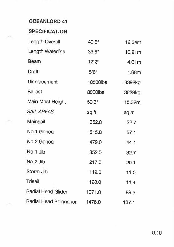
OCEANLORD 41
SPECIFICATION
Length Overall
Length Waterline
Beam
Draft
Displacement
Ballast
Main Mast Height
SAIL AREAS
Mainsail
No 1 Genoa
No 2 Genoa
No 1 Jib
No 2 Jib
Storm Jib
Trisail
Radial Head Glider
Radial Head Spinnaker
40'6"
33',6u
1z',2',
5'6u
185001bs
8000lbs
50'3"
sgft
352.0
615.0
479.0
352.0
217.O
119.0
123.0
1071.0
1476.0
12.34m
10.21m
4.01m
1.68m
8392k9
3629k9
15.32m
sqm
32.7
57.1
44.1
32.7
20.1
11.0
11.4
99.5
137.1
9.10
l: Q:. llllf,$TE,R,EV,:''YAGHTS :, F:R:E: :: it:988
INTRODUCTION
EQUIPMENT CHART
10
INTRODUCTION
lnformation on the following systems and equipments iscontained in the relevant section descriptions itemisingcurrent production yachts.
HULL Section
SAILS AND RIGGING Section
GAS SYSTEM SECIION
ELECTRICAL SYSTEMS SECIION
MAINTENANCE SectioN
Systems and equipment peculiar to pre 1988 yacht modelsare described in the following pages.
10.1

Nci
ooootsao
oo\ta
l{t-Jol-
äE oo
€€ää F:EEE ä=3EEpe==ä8söö=ööEEsEEEEEeIb--Iqooo:ddsrsöösiäFEä3gig
l{
=(5ut{t
66(I)o-c -c
LLLLLLLT-LLLLkk*=Ecggg_qgg_sEgggggg*sFFFFFFFFFFFFFFFF=-c -E -cooot(D(l)c)YY}<\\\\o o- o- o o- o o- q q q q q o q q q oö-ö-o ö ö'ö-OOOOa a o a a a aöööööööoÖÖÖÖoooo-aö ö ö ö ö ö ö 6 lit zit 6 6 6 6 6 6 -a
NNRt Y t t F - ü E q
=
= A 5 g 5 H 9 3 g $ ü g
= s 8 F E
(5
=fr[rt-v)
==.g.goo-oo-cF F E E,E g g E E E .E FO g .: E E E
oq
IIJtuY
F\Os
Ftr
oF2uJ
=gau,lFIo
JtrIJJFaIJJ
=

cr)ci
oooooo(g(9(U(['(uG(s(6(u(6(g(oJJJJJ-J
cooe"d]
5gqJ(6AJ
OOOOsfs
au)
SSSg'eNNNNN-o-o-obg09099CDCD66ooooo.o.o-o-o-o
====ä äääää*r * *s o-qr N N N N E,\ E E E E E, r- o fr ft 5 5 o o o o oFö(=
a -c g b b 5 E o o o o o '. o I O O O O Oo :f o O o 5 :f o O O -o -O g ö 2 tll LlJ LlJ LlJ LU
iD66o>666(D:(DOOO(DO)tr58 558555€)-ci=:<J:<-Y:<jb6 ä€E €E€EE€L L L L L L L L X X I g-
-+' a t F'# P P FggggggggPveclalEäöEtr tr i= tr,= tr tr tr 5 5 F F 5 üi F 5 5 5 5 5 5
-c-c-c-c-c-c-c.c.-csgggpBeB e9.9esöiDiDOaDoooooAggggyy Y!1:cyY= --o- o- o- o- o- o- o- o- d. d. cL cl o- o- o- q o. q q q o-o o ö- ö- o ö o Ö- o d o O A A a A A q A a qö ö ö ö ö ö ö Ö Ö Ö Ö o _e _e _e _e _e 9 I I -e@ a a a 6 6 6 a @ 6 a a @ a a a q a a @ U)
cccccccc
EEc EE* E EEE E sE=.g- .- =
.c .g .g .E- f .= .= .9 =,9,F,E,s,= = .g .B .EE i! tr iI iI ir- iI F iI tr i! ? ir l.t. tL tL LL F tL F tL
.omN=883=zzt-NJo o ü 6 2 ffi
=tLtLFcr)tL=F(1=(rJtr tr @ ö q ä E g fr F Z fi g z t 3 g ä A
= EEEgüi

;;.;';;.;;';;:;';;:t;:t;:l:;:1:$tEEHl
WHITLOCK SYSTEMSGobra and Mamba SystemsTitan SystemMaintenance
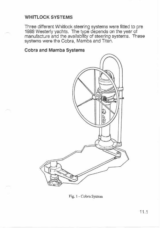
WHITLOCK SYSTEMS
Three different Whitlock steering systems were fitted to pre1988 Westerly yachts. The type depends on the year ofmanufacture and the availability of steering systems. Thesesystems were the Cobra, Mamba and Titan.
Gobra and Mamba Systems
Fig.1-CobraSystem
11.1
are shown where applicable.
1 Periodically wash the pedestal exterior with fresh water.Wax with conventional car polish.
At least twice a season, regrease the lower bearing, on theCobra lystem only via the grease nipple. Valvolenie XLgrease is recommended.
The-bearings in the pedestal, of the Mamba system only,are fully sealed and require no maintenance. The beveigears are lubricated with a specialthixotropic grease whichwill last many seasons without repacking.
any major voyage,and clamp bolt, tog-stops.
At the starl of a new season, check that the tightness ofthe 112' UNF nyloc nuts, securing the rose joints to theoutput lever and tiller lever, are säcure.
On the Cobra system, check that the 5/8" UNF brass locknuts on the draglink are tight.
Check that the universaljoint pinch bolts are secure.
11.2
10 On the Mamba svstem, touch up any chips on the paint-work immediately using lnternationaiYacht enamel' Forlarger areas, priör to top coat, use a two-paft aluminiuetch primer.
Titan System
This system uses two stainless steel wires running incondu-it to a quadrant fitted to the rudder stock. The cablesare adjusted and tensioned at the quadrant.
11.3
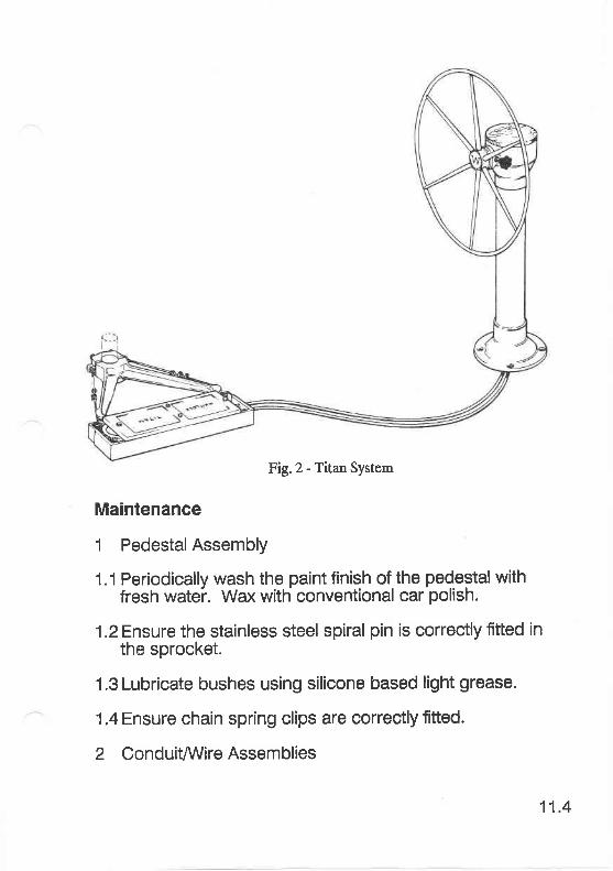
Fig.2 - Titan System
Maintenance
1 Pedestal Assembly
1.1 Periodically wash the paint finish of the pedestal withfresh watei. Wax with conventional car polish.
1.2 Ensure the stainless steel spiral pin is correctly fitted inthe sprocket.
1.3 Lubricate bushes using silicone based light grease.
1.4 Ensure chain spring clips are correctly fitted.
2 ConduitArVire Assemblies
11.4
2.1 Al the start of the season, inspect conduit for signs ofwear or damage.
2.ZLubricate conduits with silicone based light grease.
2.3 Examine the wire for signs of wear or damage.
and no'feel'.
3 Quadrant
3.1At least twice a season and before any major voyage,check security of quadrant bolts. Lubricate eyebolts andsheave bush with silicone based light grease.
3.2At the start of the season check, rigidity of quadrant unit.
Note: The stainless steel wire used has a finite life. lt isrecommended that it be renewed after every lifthseason.
11.5
ENGINE SYSTEMS
STERN GEARBukh SystemBronze lnboard Gland Assemblies
ENGINE SYSTEMS
following addresses may helP:
STERN GEAR
Various types of stern gear were fitted to older models.
Bukh System
Reservoir
Stern Tube Hexible TubeRear Bearing
Stuffing Box
Ffg. 1- Brrkh Slatem
12.1
Notes:
1 The reservoir illustrated in Fig. 1 is an optional extra.It should be mounted approximately 0.25m above thewater line and filled with outboard gear oil.
2 Every 3 seasons, renew the 3 ring seals in the stuffingbox (A).
3 Excessive oil consumption indicates defective ringseals.
Bronze lnboard Gland Assemblies
Some early yachts are fitted with bronze inboard glandassemblieS with centralising bearings which require reEulargreasing. This can be achieved using a remote mountedstern gland greaser.
12.2
,i3;',IItfAfClH ,,,,$tlSTEffi$:,:;':,:HH:8,':,i1,988,,,,
WATERA/VAST SYSTEMS
I.AVAC MARINE TOILETOperating lnstructionsMaintenanceWinterisationPump ValvesSpare Parts
I-AVAC TOILET WITH HOLDING TANKOperation
SL 4OO SERIES MARINE TOILETOperating I nstructionsSpare Parts
13
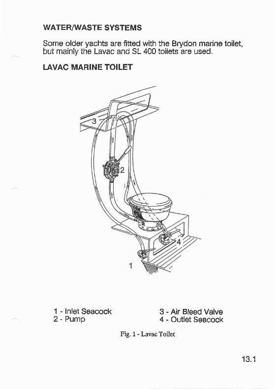
WATERAÄIASTE SYSTEMS
Some older yachts are fitted with the Brydon marine toilet,but mainly the Lavac and SL 400 toilets are used.
LAVAC MARINE TOILET
1 - lnlet Seacock2 - Pump
3 - Air Bleed Valve4 - Outlet Seacock
Fig.1- LavacToilet
13.1
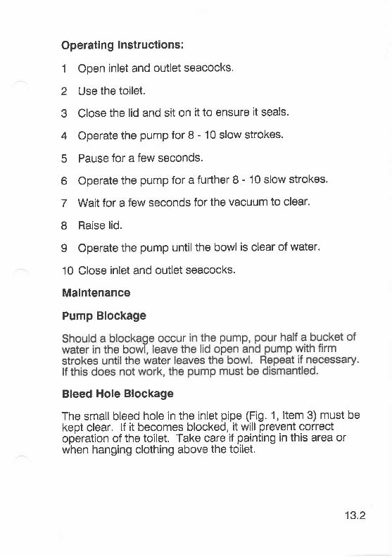
Operating lnstructions:
1 Open inlet and outlet seacocks.
2 Use the toilet.
3 Close the lid and sit on it to ensure it seals.
4 Operate the pump for 8 - 10 slow strokes.
5 Pause for a few seconds.
6 Operate the pump for a furlher 8 - 10 slow strokes.
7 Wait for a few seconds for the vacuum to clear.
8 Raise lid.
I Operate the pump until the bowl is clear of water.
10 Close inlet and outlet seacocks.
Maintenance
Pump Blockage
Bleed Hole Blockage
The small bleed hole in the inlet pipe (Fig. 1, ltem 3) must bekept clear. lf it becomes blocked, it will prevent correctoperation of the toilet. Take care if painting in this area orwhen hanging clothing abovr the toilet.
13.2
winterisation
When laying up the yacht for the winter, it is re_commendedthat the ioitöt tie wellflushed and then dried. Carry out theoperation in 'Pump Blockage' severaltimes. Remove theoi-rtlet hose at the'seacockänd pump the toilet into a bucketuntil dry. Reconnect the outlet hose and ensure theseacocks are closed.
Pump Valves
After 2-3 years, the pump valves may'fur-up'.from salt wateraction. This sialing'is eäsi[ removeh by flöxing the rubberand scraping gently. lt is rdcommended that the pump ischecked every 2years and descaled as necessary.
Spare Parts
Spare parts and repair information can be obtained fromvriesteily Yachts Ltä. or direct from:
Blake & Sons Limited, PO Box 15, Sunbeam Works,GOSPORT, Hants. PO12 2HG Tel: (0705) 583322
I.AVAC TOILET WITH HOLDING TANK
Some exporl yachts are fitted with a holding tank wastesystem as illustrated in Fig. 2.
13.3
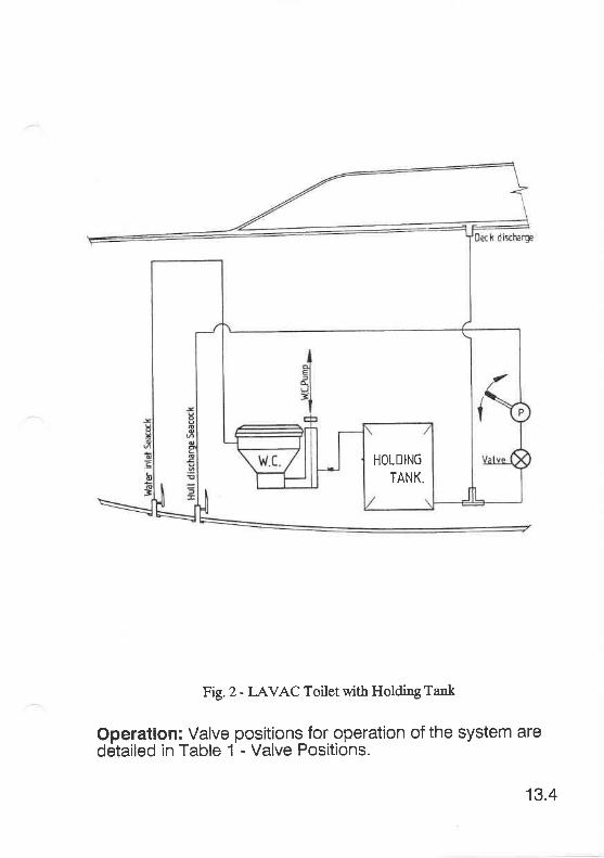
HOLDIN6
TANK.
Fig.2- I-AVAC Toilet with Holding Tank
Operation: Valve positions for operation of the system aredetailed in Table 1 - Valve Positions.
13.4
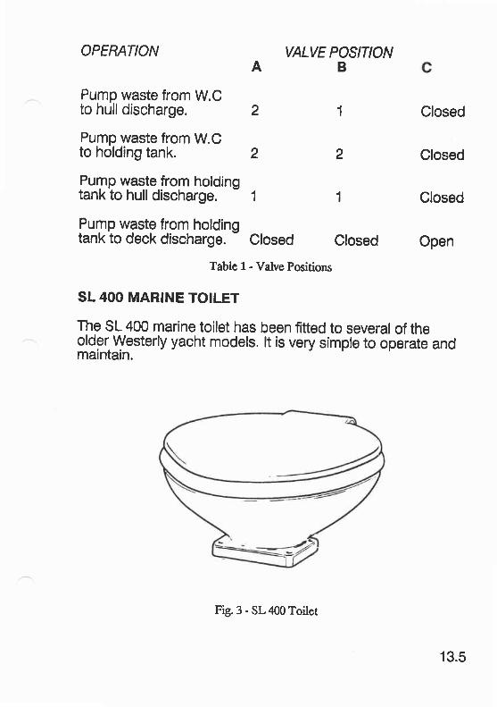
OPERATIONA
Pump waste from W.Cto hull discharge. 2
Pump waste from W.Cto holding tank. 2
VALVE POSITIONB
Pump waqle from holdingtank to hull discharge. - 1 1
PrFp waste from holdingtank to deck discharge. - Closed Closed
1 Closed
2 Closed
Glosed
Open
Table 1 - Valve Positions
SL 4OO MARINE TOILET
The SL 400 marine toilet has been fitted to several of theoldgr. Westerly yacht models. lt is very simple to operate andmaintain.
Fig. 3 - SL 400 Toilet
13.5
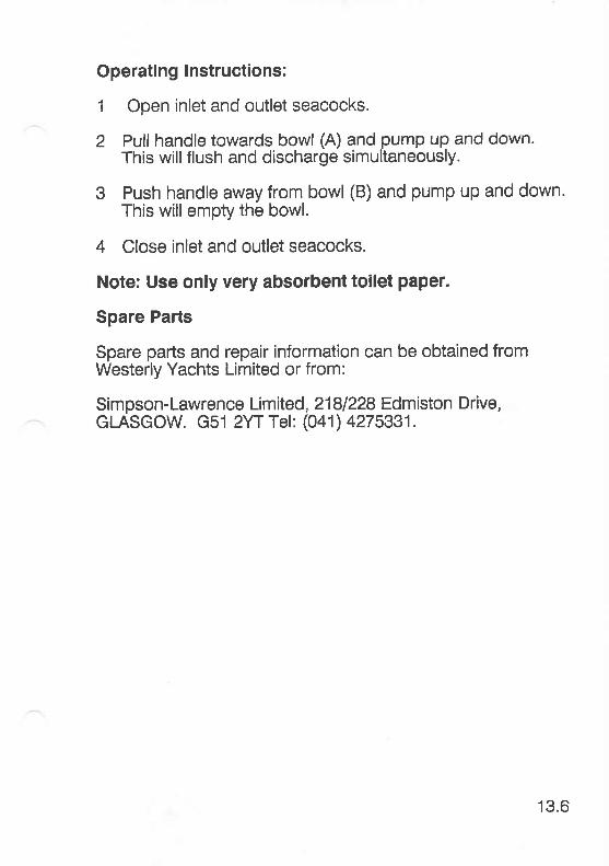
Operating lnstructions:
1 Open inlet and outlet seacocks.
2 Pull handle towards bowl (A) and pump up and down.This willflush and discharge simultaneously.
3 Push handle away from bowl (B) and pump up and down.This will empty the bowl.
4 Close inlet and outlet seacocks.
Note: Use only very absorbent toilet paper.
Spare Parts
Spare parts and repair information can be obtained fromWesterly Yachts Limited or from:
Simpson-Lawrence Limited, 2181228 Edmiston Drive,GLASGOW. G51 2YTTel: (041) 4275331.
'13.6
Operating lnstructions:
1 Open inlet and outlet seacocks.
2 Pull handle towards bowl (A) and pump up and down.This willflush and discharge simultaneously.
3 Push handle away from bowl (B) and pump up and down.This will empty the bowl.
4 Close inlet and outlet seacocks.
Note: Use only very absorbent toilet paper.
Spare Parts
Spare parts and repair information can be obtained fromWesterly Yachts Limited or from:
Simpson-Lawrence Limited, 2181228 Edmiston Drive,GI-ASGOW. G51 2YTTel: (041) 4275331.
13.6
Top Related