


Languages
Pages
Legal


MOD-GSM-EDGE development boardUsers Manual
All boards produced by Olimex are ROHS compliant
Rev. B, July 2012
Copyright(c) 2012, OLIMEX Ltd, All rights reserved
Page 1

INTRODUCTIONMOD-GSM-EDGE, connected to other Olimex board with UEXT connector is excellent choice for adding remote monitoring and control in remote places by GSM cellular network. Depending on the features of the other board, for example, you can transfer digital data, measure analog values, connect to internet by GSM network. MOD-GSM-EDGE can be connected to computer via on-board mini USB connector. Also the board can work in standalone mode, but only when the SIM card is without PIN code. In standalone mode MOD-GSM-EDGE requires usage of AT commands. It can receive information by GSM network, but if you want to operate with this information, you will need appropriate board with UEXT connected to MOD-GSM-EDGE. Choose the other board depending on the application you want to have. MOD-GSM-EDGE contains SIM700D - quad-band GSM GPRS/EDGE module 850/900/1800/1900Mhz inside which covers most used GSM networks around the world. SIM700D supports EDGE protocol which assures faster data transfer. The GSM antenna is built in the board so no need for external expensive GSM antennas.
BOARD FEATURES
• SIM700D - GSM/GPRS/EDGE quad-band MODULE 850/900/1800/1900Mhz with build on-board GSM cellular antenna
• Li-ion backup battery 3.7 V 1200mA for up to 200 hours of GSM module stand-by
• SIM-card holder• USB mini interface• Status LED • On-GSM module temperature sensor • UEXT connector• PWR_EXT connector• PWRKEY button• On-board DC-DC converter for standalone mode and battery charger• PCB: FR-4, 1 mm (0,039"), solder mask, silkscreen component print• Dimensions: 79.2x57.6 mm (3.118x2.268")
ELECTROSTATIC WARNING
The MOD-GSM-EDGE board is shipped in protective anti-static packaging. The board must not be subject to high electrostatic potentials. General practice for working with static sensitive devices should be applied when working with this board.
BOARD USE REQUIREMENTS
Hardware: 12V, 800mA Power Supply, if you want to recharge the battery. An Olimex board with UEXT.Mini USB cable.
Important: If your board does not work, first try to charge the battery as you power supply the board for few hours.
Page 2

MODULE FEATURES
− Power Supply – Single Supply voltage 3.4V – 4.5V
− Power saving – Typical power consumption in SLEEP mode (BS-PA-MFRMS=5) is 4mA
− Frequency bands:
− Quad-band: GSM 850, GSM 900, DCS 1800, PCS 1900.
− Compliant to GSM Phase 2/2+
− GSM class – Small MS
− Transmit Power
− GMSK:− Class 4 (2W)@GSM850/GSM900− Class 1 (1W)@DCS1800/PCS1900
− 8PSK:
− Class E2 (0.5)@GSM850/GSM900
− Class E2 (0.4W)@DCS1800/PCS1900
− GPRS connectivity
− Multi-slot class 12
− Coding scheme: CS1~4
− Mobile station class B
− EDGE connectivity
− Multi-slot class 12
− Modulation and coding scheme: MCS1~9
− Mobile station class B
− DATA transfer
− CSD: up to 9.6kbps, support non-transparent and transparent mode
− GPRS: downlink max: 85.6kbps; uplink max: 85.6kbps
− EDGE: downlink max: 236.8kbps; uplink max: 236.8kbps
− Coding scheme: CS1~4, MCS1~9
− Support PBCCH
− Support USSD
− TCP/IP protocol stack – Access by AT commands
− Temperature range
− Normal operation: -20oC to +60oC
− Restricted operation: -30oC to -20oC and +60oC to +80oC (1)
− Storage temperature: -40oC to +85oC
− SIM interface – Support SIM card: 3V and 1.8V
− External antenna – connected via 50 Ohm antenna pad
Page 3

− Audio features
− Speech codec modes:
− Half Rate (ETS 06.20)
− Full Rate (ETS 06.10)
− Enhanced Full Rate (ETS 06.50/06.60/06.80)
− Echo Cancellation
− Noise reduction
− AMR
− Main serial port
− Seven lines on Main serial Port
− CSD FAX, GPRS/EDGE services
− AT commands of controlling module
− Multiplexing function
− Autobauding baud rate
− USB interface – support an USB 2.0 Full Speed (12Mbit/s) device interface
− Phonebook management – support phonebook types: SM, LD, MC, RC, ME, ON, VM, LA, DC, SD, FD, BN
− SIM Application Toolkit – support SAT class 3, GSM 11.14 Release 99
− Real Time clock – implemented
− Timer function – Programmable via AT commands
− Physical characteristics
− Size: 43.5x26x2.9 mm
− Weight: 7g
− Firmware upgrade – via main serial port or USB interface
(1) SIM700D works, but deviations from GSM specification may cause errors.
Page 4

FUNCTIONAL DIAGRAM
Page 5

Page 6

SCHEMATIC
4V_E DCDC_E BAT_E 4V USB_PWR/USB_CHG 5V_CHG_E
Jumpers: Mode of operation:
Close Close Open OpenClose Close Open GSM module is supplied by PWR jack or USB
Open Close Close Open Open Close Close GSM module is supplied by Battery.Battery can be charged if USB or External power supply is present!
NA
NA
0
ON
GSM_PCB_ANT
TB3_3.5MM
HN1x2(Open)
HN1x2
1000uF/16VDC 2.2uF 100nF
4.7nF10uF/10V/1206 220uF/10V/tant 1000uF/6.3V/8x12/low_ESR
NA(10nF)
NA(470pF) NA(470pF) 220nFNA(470pF)
10n
10uF/10V/1206
47uF/10V
CE2200uF/6.3V/LO
W ESR
/10x20mm
RM
5
220uF/10V/tant
100nF
10uF/16V/TANT
CE2200uF/6.3V/LO
W ES
R/10x20m
m R
M5
1N4004(SMD)
1N5822(SMC)
1N5819S
1N5819S
0
OP
EN
IRLM
L6402
BSS138
15uH/DBS135
+5VVBAT
VBAT
+5V
+12V
VBAT+12V
VBAT
VBAT
+12V
+5V
TB2_3.5MM
WU6S
BC817
68k3.3K
150k
4.99k/1% 15k/1% 4.99k/1% 1K
33K
560R
NA(10K)22R
22R
22R
10K
1M10KNA
NA
10K 33K 10K
1K3.3K1K1K
1K1K1K1K
220220
33K
150k
150k
33K
SIM-HOLDER
red
SIM700D
BH10R
MINI_USB
BD9778HFP
TXD,RXD,RTS,CTS,DTR,RI,DBG_TX,DBG_RX,MAIN_RX,MAIN_TX
VS
IM,S
IMD
ATA
,SIM
CLK
, SIM
RS
T
AUXADC
AUXADC
CHG_CTRL
CHG_CTRL
CTS
CTS
DBG_RXDBG_RX
DBG_TX
DBG_TXDTR
DTRMAIN_RX
MAIN_RX
MAIN_TX
MAIN_TX
NETLIGHT
NETLIGHT
PWRKEY
PWRKEY
RI
RI
RTS
RTS
RXD
RXD
SIMCLK
SIMCLK
SIMDATA
SIMDATA
SIMRST
SIMRST
TEMP_BAT
TEMP_BAT
TXD
TXD
VSIM
VSIM
1 24V
1 24V_E
12
5V_CHG_E
1 2
AGND_E
ANT
123
BAT
1 2
BAT_E
12 BTLD_E
C1C2 C3 C4
C5 C6 C7
C8
C9 C10 C11C12
C13
C14 C15 C16
C17
C18
C19
C20
D1
D2
D4
D5
1 2DCDC_E
12
DO
WN
LOA
D
FET1
FET2
GND
L1
1
2
3
MRX/DRX
1
2
3
MTX/DTX
12
PWR
PWRKEY
123456
PWR_EXT
Q1
R1
R2R3
R4 R5 R6 R7
R8
R9
R10R11
R12
R13
R14
R15
R16R17
R18
R19 R20 R21
R22R23R24R25
R26R27R28R29
R30R31
R32
R33
R34
R35
GND4
SIMCLK3SIMIO
6
SIMNC5SIMRST2
VCC1
SIM
STAT
ADC049
AGND138
AGND243
AGND348
ANTENNA53
BOOTCTRL13
BT_EN30
BT_RXD32BT_TXD31
CTS25
DBG_RXT18DBG_TXT17DCD27
DISP_CLK11
DISP_CS9
DISP_D/C10
DISP_DATA12
DISP_RST14
DTR26
GND11
GND222
GND351
GND452
GND554
GND655
GND756
GND857
GPIO150
JACKSENSE7
MIC1N47
MIC1P46
MIC2N44MIC2P45
NETLIGHT15
PWRKEY19
RI28
RTS29
RXD24
SIM_CLK36SIM_DATA34
SIM_RST35
SIM_VDD37
SPK1N42
SPK1P41
SPK2N39SPK2P40
STATUS8
TEMP_BAT5
TXD23USB_DN
20
USB_DP21
VBAT12
VBAT23
VCHG4
VDD_EXT16
VRTC33
VUSB_IN6
U1
1 23 45 67 89 10
UEXT
D+D-
GND
GN
D1
GN
D2
GN
D3
GN
D4
ID
VBUSUSB
1
2
3
USB_PWR/USB_CHG
EN/SYNC7
FB3GND4
INV5
RT6SW
2VIN1
VR1
9-12VDC
MOD-GSM-EDGERev. B
COPYRIGHT(C) 2010, Olimex Ltd.
http://www.olimex.com/dev
+
+ +
+ + +
+
+
GSD
GS
D
US
B
5V_INGNDVBATPWR_INGPIO1AUXADC
0
BOARD LAYOUT
Page 8
Page 9

POWER SUPPLY CIRCUIT
The MOD-GSM-EDGE board may be supplied in different ways:
1. External power supply (+9 – 12VDC), or USB power supply without using the internal backup battery.The module is powered only from external 12V and the battery is not connected. In this case:− jumper BAT_E must be open− jumper 4V_E must be closed− jumper 4V must be closed − jumper 5V_CHG_E must be open. − USB_PWR/USB_CHG must be in position USB_PWR− DCDC_E must be closed− BTLD_E must be open
Power consumption in this mode is:− Up to 70mA when during conversation.− Around 20mA in normal mode (no conversation in progress).
Important: 4V_E, 4V and 5V_CHG_E jumpers have to be moved together.
2. Power from +12VDC with backup battery.The module is powered with battery and allows battery charging. In this case:− jumper BAT_E must be closed− jumper 4V_E must be open− jumper 4V must be open − jumper 5V_CHG_E must be closed − USB_PWR/USB_CHG must be in position USB_CHG− DCDC_E must be closed− BTLD_E must be open− Power consumption in this mode:
Depends on live of the battery and vary from 270mA to 330mA (related to external power supply). If we supply the module only via the battery, without external power supply, the current through the battery is between 12mA and 18mA when GSM is connected to the network (stat led blinks with frequency ~ 0.25Hz) if there is no conversation in progress, and between 60mA to 180mA during conversation.
Page 10
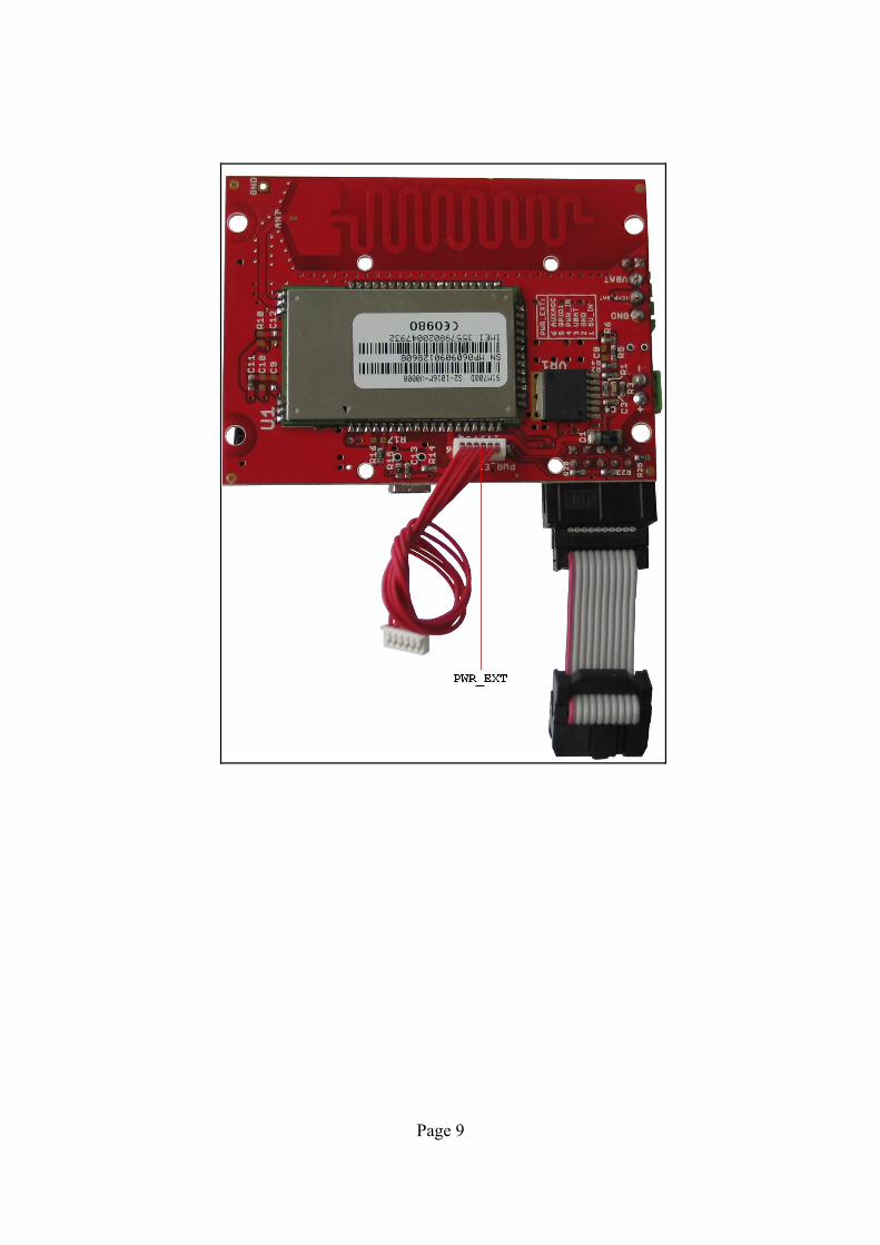
CONNECTOR DESCRIPTIONSUEXT
Pin # Signal Name
1 NC
2 GND
3 RXD
4 TXD
5 RTS
6 CTS
7 DTR
8 CHG_CTRL
9 RI
10 PWRKEY
This connector allows connecting to other Olimex boards with UEXT connector.
SIM-CARD
Pin # Signal Name
1 VSIM
2 SIMRST
3 SIMCLK
4 GND
5 NC
6 SIMDATA
This is standard SIM card connector, to operate MOD-GSM-EDGE should have inserted valid SIM card for your operator network.
Page 11

PWR-CON
Pin # Signal Name
1 +12V
2 GND
This connector is used to power the MOD-GSM-EDGE. External (+9-12VDC) power source have to be applied to this pins.
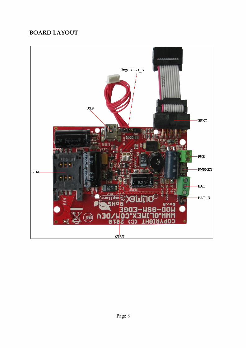
PWR_EXT
Pin # Signal Name Description
1 5V_IN 5V input for battery recharge
2 GND Ground
3 VBAT Output – for power supplying other devices from the GSM battery
4 PWR_IN Optional input for external power supply
5 GPIO1 Doesn't work
6 AUXADC Input for analog signal
BAT
Pin # Signal Name
1 GND
2 TEMP_BAT
3 Via jmp BAT_E to VBAT
Note: The battery doesn't support TEMP_BAT.
Page 12
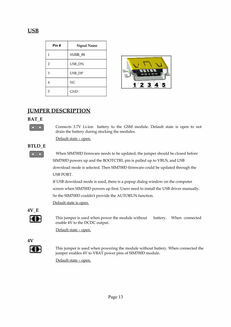
USB
Pin # Signal Name
1 VUSB_IN
2 USB_DN
3 USB_DP
4 NC
5 GND
JUMPER DESCRIPTIONBAT_E
Connects 3.7V Li-ion battery to the GSM module. Default state is open to not drain the battery during stocking the modules.
Default state – open.
BTLD_E When SIM700D firmware needs to be updated, the jumper should be closed before
SIM700D powers up and the BOOTCTRL pin is pulled up to VBUS, and USB
download mode is selected. Then SIM700D firmware could be updated through the
USB PORT.
If USB download mode is used, there is a popup dialog window on the computer
screen when SIM700D powers up first. Users need to install the USB driver manually.
So the SIM700D couldn't provide the AUTORUN function.
Default state is open.
4V_EThis jumper is used when power the module without battery. When connected enable 4V to the DCDC output.
Default state – open.
4VThis jumper is used when powering the module without battery. When connected the jumper enables 4V to VBAT power pins of SIM700D module.
Default state – open.
Page 13

5V_CHG_EThis jumper is used when the battery is present and allows battery charging. Connects the DCDC converter output (5V or 4V according 4V_E jumper state) to VCHG power pin of SIM700D module.
Default state closed
Important: 4V_E, 4V and 5V_CHG_E jumpers have to be moved together.
Do not plug in external +12V if BAT_E jumper is open!
DCDC_EEnable DCDC. Connect DCDC output (5V or 4V according 4V_E jumper state) to the module.
Default state closed
DownloadWhen the jumper is closed SIM700D firmware upgrade is allowed.
Default state – open
MTX/DTXThe MainTX/DebugTX defines whether Main TX terminal or Debug TX terminal of SIM700D module is connected to FT232RL virtual com port driver.
Default state is DTX
MRX/DRX The MainRX/DebugRX define whether Main RX terminal or Debug RX terminal of SIM700D module is connected to FT232RL virtual com port driver.
Default state is DRX
AGND_EEnable board analog ground.
Default state is closed
USB_PWR_EEnable USB +5 V power supply.Default state is closed
Page 14

INPUT/OUTPUT
PWRKEY button – turns on the MOD-GSM-EDGE module. You can turn on the SIM700D by driving the PWRKEY to a low level voltage for period time from 500mS to 1S Status LED (red) with name STAT – indicates the state of SIM700D module.STAT is off state - SIM700D is not running64ms On/ 800ms Off - SIM700D does not find the network64ms On/ 3000ms Off - SIM700D find the network64ms On/ 300ms Off - GPRS communication
IMPORTANT NOTE ABOUT THE UEXT
If MOD-GSM doesn't transmit properly data on the UEXT of another Olimex board, it might be because some other boards can interfere with MOD-GSM's signals. If the host board has any signal on the I2C and/or the SPI on the UEXT there is very high chance of erroneous behavior.
There are two workarounds:
1. Cut the UEXT cable wires 5,6,7,8,9,10. Only wires 1,2,3,4 (NC, GND, RXD, TXD) should remain.
OR
2. Remove resistors R23, R24, R25, R27, R28, R29
Page 15

MECHANICAL DIMENSIONS
All measures are in inches.
Page 16

AVAILABLE DEMO SOFTWARE
- EW-ARM Demo code for MOD-GSM and MOD-GSM-EDGE (high speed) GSM modules connected to STM32-LCD board by Olimex.
ORDER CODE
MOD-GSM-EDGE assembled and tested.
How to order? You can order to us directly or by any of our distributors. Check our web www.olimex.com/dev for more info.
All boards produced by Olimex are ROHS compliant
Revision history:
Board's revision: REV. B - created July 2010
Manual's revision: REV. Initial - created March 2011 REV. B - July 2012
Page 17
Disclaimer:
© 2011 Olimex Ltd. All rights reserved. Olimex®, logo and combinations thereof, are registered trademarks of Olimex Ltd. Other terms and product names may be trademarks of others.
The information in this document is provided in connection with Olimex products. No license, express or implied or otherwise, to any intellectual property right is granted by this document or in connection with the sale of Olimex products.
Neither the whole nor any part of the information contained in or the product described in this document may be adapted or reproduced in any material from except with the prior written permission of the copyright holder.
The product described in this document is subject to continuous development and improvements. All particulars of the product and its use contained in this document are given by OLIMEX in good faith. However all warranties implied or expressed including but not limited to implied warranties of merchantability or fitness for purpose are excluded.
This document is intended only to assist the reader in the use of the product. OLIMEX Ltd. shall not be liable for any loss or damage arising from the use of any information in this document or any error or omission in such information or any incorrect use of the product.
Page 18
Top Related