


Languages
Pages
Legal


MATHIEU GAUTHIERPIERRE POULIN
LIGUM, DEPT. I.R.O.UNIVERSITÉ DE MONTRÉAL
GRAPHICS INTERFACE 2009GRAPHICS INTERFACE 2009
Preserving Sharp Edges in Geometry Images

Geometry Images
Simple mesh representation data structure Encodes mesh geometry and connectivity in
an image-like array
What are they?
257 × 257 Geometry Image
Reconstruction
Vertices PositionsVertices Positions4 Neighbours = 1 Quad
4 Neighbours = 1 Quad

Geometry ImagesHow to create them?
Original ModelOriginal Model CutCut SamplingSampling Geometry ImageGeometry Image
ReconstructionReconstructionSampling GridSampling GridParameterizationParameterization

Motivation
…And there in lies the problem: The regular grid used to sample the parameterization cannot capture sharp features
The problem

Motivation
Add constraints such that sharp features align with the sampling grid in the parameterization domain
It makes the process very difficult to converge
Non-linear, energy function is not smooth, infinity or no good solution
One solution
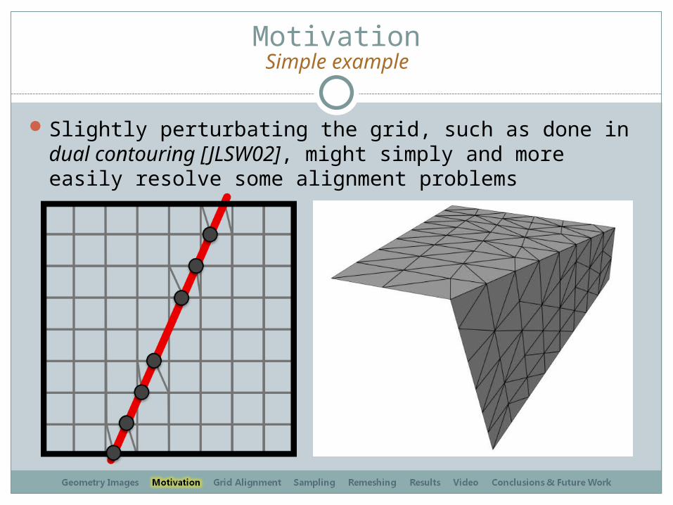
MotivationSimple example
Slightly perturbating the grid, such as done in dual contouring [JLSW02], might simply and more easily resolve some alignment problems

Grid Alignment to the Sharp FeaturesIdentifying sharp features
Input 3D ModelInput 3D Model ParameterizationParameterization
Sharp Edge Sharp CornerSharp Corner
Chain of Sharp Edges = Sharp Segment

Grid Alignment to the Sharp FeaturesCorner & Edge Snapping - Part 1
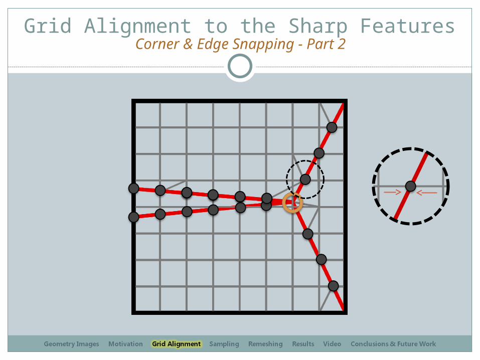
Grid Alignment to the Sharp FeaturesCorner & Edge Snapping - Part 2

Grid Alignment to the Sharp FeaturesCorner & Edge Snapping - Part 3

Sampling
UVs coordinates are no longer implicitWe can no longer use 1 normal per vertex, we
need more, especially for lighting.
What about UVs and normals?

SamplingNormals
Because of the regular structure of the geometry image and the way we remesh, we will never need more than 8 normals around a vertex (one per octant)
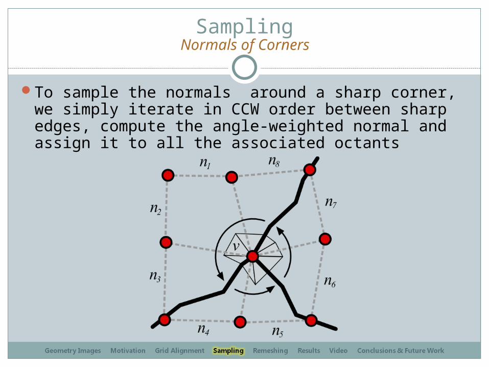
SamplingNormals of Corners
To sample the normals around a sharp corner, we simply iterate in CCW order between sharp edges, compute the angle-weighted normal and assign it to all the associated octants

Sampling
For a sample snapped to a sharp edge, the procedure is very similar, only two normals will be computed and stored, in the respective octant
Normals of Sharp Edges

SamplingBack to Our Example
12
3
4 5
6
78

SamplingBack to Our Example
1
2
3
4 5
6
7
8
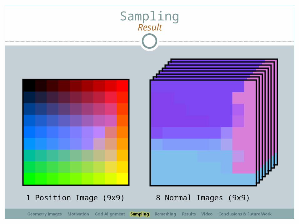
SamplingResult
1 Position Image (9x9) 8 Normal Images (9x9)
RemeshingAlgorithm
Remeshing from geometry images is very similar to the original method
A vertex is created for each image pixelFor each group of four pixels, two triangles
are created…But since we have up to 8 normals per
vertex, more vertices may need to be createdFaces must also be connected to the
appropriate vertices

Remeshing
1. For each image pixel, we create as many vertices as there are different normals (up to 8) and store them in an array[8]
2. When creating the faces, we use the following rule to select which vertex to connect.
Algorithm
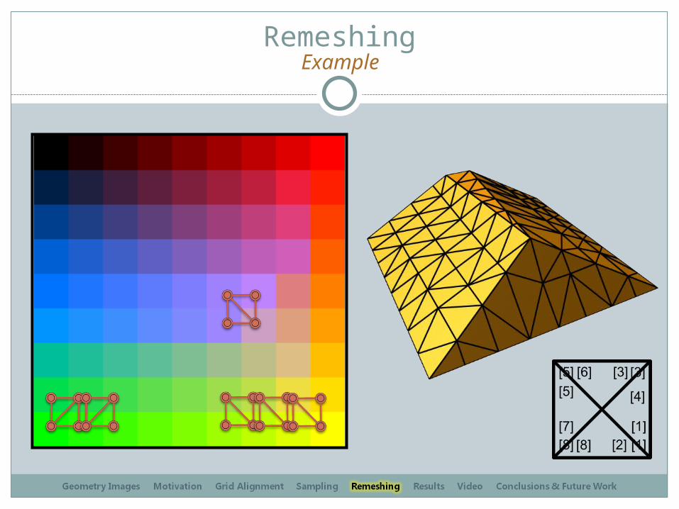
RemeshingExample

ResultsSquare Torus (Original Model)

ResultsSquare Torus (Comparison)
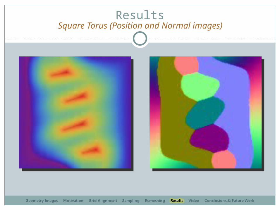
ResultsSquare Torus (Position and Normal images)
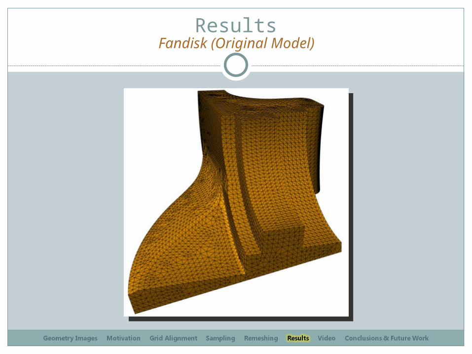
ResultsFandisk (Original Model)

ResultsFandisk (Remeshings)
129×129 Geometry Images33×33 Geometry Images
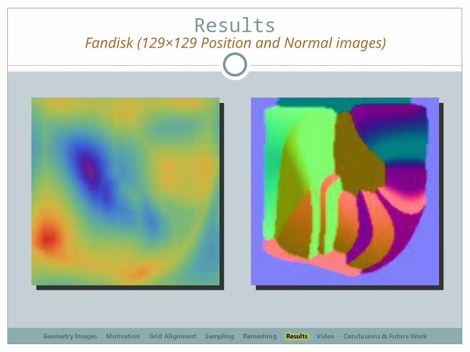
ResultsFandisk (129×129 Position and Normal images)
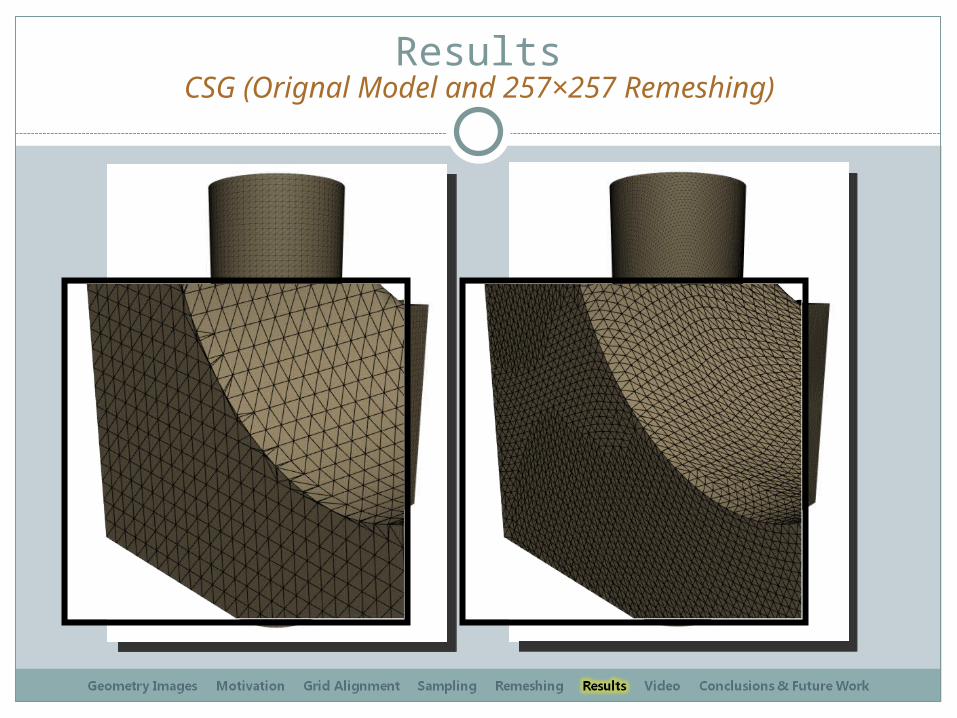
ResultsCSG (Orignal Model and 257×257 Remeshing)

Results257×257 Positon and Normal Geometry Images
Results
Start!
Video
Conclusion
Simple and efficient techniqueDoes not over-constrain the parameterization
processCan be added to any geometry image
generation pipelineCan only encode a maximum of 8 normalsMust store these 8 normals and 1 uv
coordinates
Wrap up

Future Work
Once the grid is snapped to sharp features, it may be possible to add an extra relaxation step to deform the parameterization and bring back the grid to a regular shape
Try something other than a greedy algorithm, maybe something like a quadric error metric could help find a better overall solution

Thank You!
Questions? Comments?
Top Related