


Languages
Pages
Legal


Logic Design Fundamentals - 1
Lecture L1.1
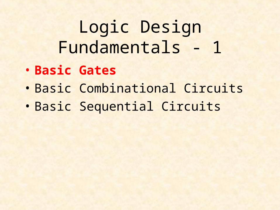
Logic Design Fundamentals - 1
• Basic Gates
• Basic Combinational Circuits
• Basic Sequential Circuits

Basic Gates
• NOT Gate
• AND Gate
• OR Gate
• XOR Gate
• NAND Gate
• NOR Gate
• XNOR Gate
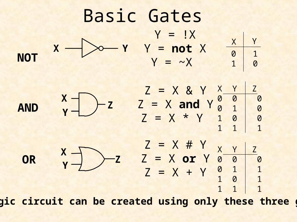
Y = !XY = not XY = ~X
Basic Gates
NOT
X Y
01
10
X
YZ
X Y
X Y
Z
AND
OR
X Y Z0 0 00 1 01 0 01 1 1
X Y Z0 0 00 1 11 0 11 1 1
Z = X & YZ = X and YZ = X * Y
Z = X # YZ = X or YZ = X + Y
Any logic circuit can be created using only these three gates
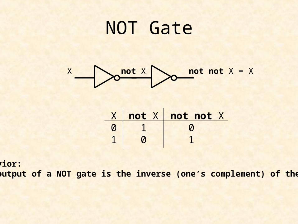
NOT Gate
X not X not not X = X
X not X not not X0 1 01 0 1
Behavior:The output of a NOT gate is the inverse (one’s complement) of the input

AND Gate
X(1)X(2)
X(n)
ZAND
Behavior:The output of an AND gate is HIGH only if all inputs are HIGH
Z = X(1) and X(2) and …. and X(n)

4-Input AND GateX(1)
X(2)
X(3)
X(4)
Z
X(1)
X(2)
X(4)
ZANDX(3)
X(1)
X(2)
X(3)
X(4)
Z
3-Level
2-Level
Behavior:Z := '1';for i in 1 to 4 loop Z := Z and X(i);end loop;

std_logic_1164.vhd TYPE std_ulogic IS ( 'U', -- Uninitialized 'X', -- Forcing Unknown
'0', -- Forcing 0 '1', -- Forcing 1 'Z', -- High Impedance
'W', -- Weak Unknown 'L', -- Weak 0 'H', -- Weak 1 '-' -- Don't care );
SUBTYPE std_logic IS resolved std_ulogic;
SUBTYPE UX01 IS resolved std_ulogic RANGE 'U' TO '1'; -- ('U','X','0','1')
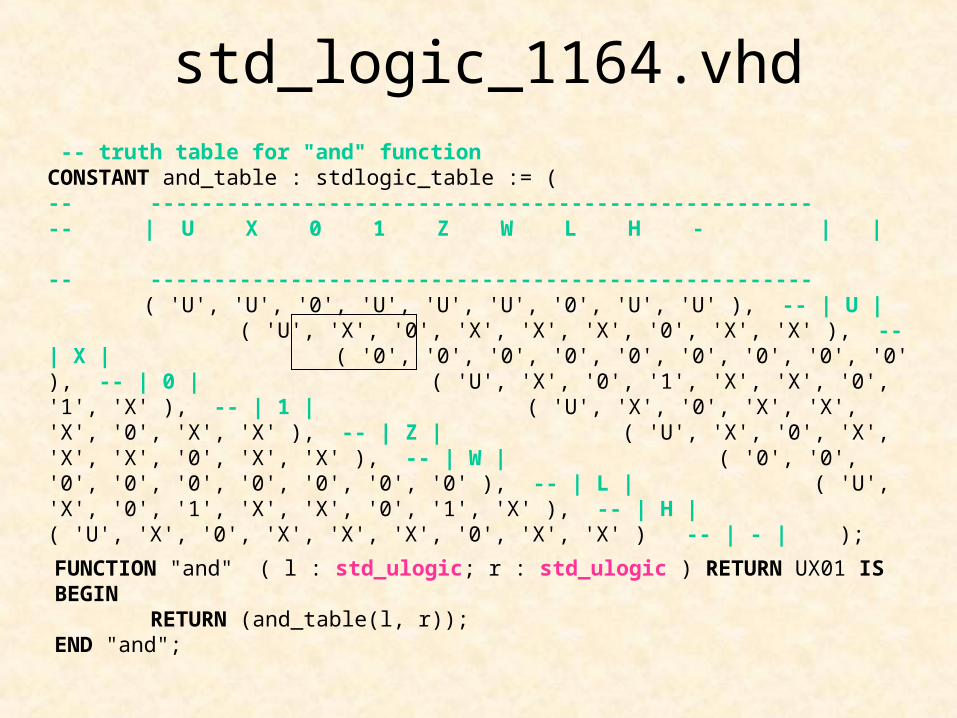
std_logic_1164.vhd -- truth table for "and" function CONSTANT and_table : stdlogic_table := ( -- ---------------------------------------------------- -- | U X 0 1 Z W L H - | | -- ---------------------------------------------------- ( 'U', 'U', '0', 'U', 'U', 'U', '0', 'U', 'U' ), -- | U | ( 'U', 'X', '0', 'X', 'X', 'X', '0', 'X', 'X' ), -- | X | ( '0', '0', '0', '0', '0', '0', '0', '0', '0' ), -- | 0 | ( 'U', 'X', '0', '1', 'X', 'X', '0', '1', 'X' ), -- | 1 | ( 'U', 'X', '0', 'X', 'X', 'X', '0', 'X', 'X' ), -- | Z | ( 'U', 'X', '0', 'X', 'X', 'X', '0', 'X', 'X' ), -- | W | ( '0', '0', '0', '0', '0', '0', '0', '0', '0' ), -- | L | ( 'U', 'X', '0', '1', 'X', 'X', '0', '1', 'X' ), -- | H | ( 'U', 'X', '0', 'X', 'X', 'X', '0', 'X', 'X' ) -- | - | );
FUNCTION "and" ( l : std_ulogic; r : std_ulogic ) RETURN UX01 IS BEGIN
RETURN (and_table(l, r)); END "and";

OR Gate
Behavior:The output of an OR gate is LOW only if all inputs are LOW
Z = X(1) or X(2) or …. or X(n)
X(1)
X(2)
X(n)
ZOR

4-Input OR Gate
X(1)
X(2)
X(4)
ZORX(3)
X(1)
X(2)
X(3)
X(4)
Z
3-Level
2-Level
Behavior:Z := '0';for i in 1 to 4 loop Z := Z or X(i);end loop;
X(1)
X(2)
X(3)
X(4)Z
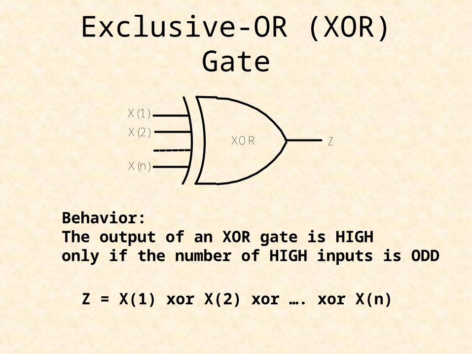
Exclusive-OR (XOR) Gate
Behavior:The output of an XOR gate is HIGH only if the number of HIGH inputs is ODD
Z = X(1) xor X(2) xor …. xor X(n)
X(1)
X(2)
X(n)
ZXOR
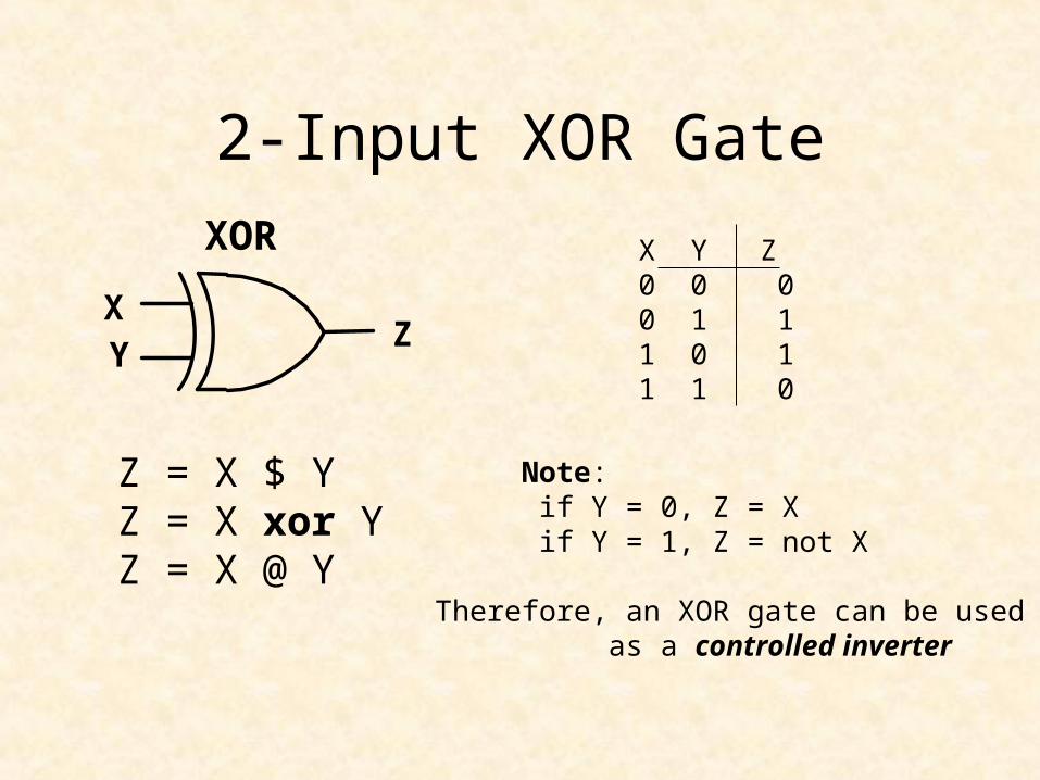
2-Input XOR Gate
XOR X Y Z0 0 00 1 11 0 11 1 0
Z = X $ YZ = X xor YZ = X @ Y
X Y
Z
Note: if Y = 0, Z = Xif Y = 1, Z = not X
Therefore, an XOR gate can be used as a controlled inverter
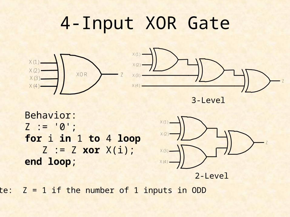
4-Input XOR Gate
X(1)
X(2)
X(4)
ZXORX(3)
X(1)
X(2)
X(3)
X(4)
Z
3-Level
2-Level
Behavior:Z := '0';for i in 1 to 4 loop Z := Z xor X(i);end loop;
X(1)
X(2)
X(3)
X(4)Z
Note: Z = 1 if the number of 1 inputs in ODD

NAND Gate (NOT-AND)
Behavior:The output of an NAND gate is LOW only if all inputs are HIGH
Z = not (X(1) and X(2) and …. and X(n))
X(1)
X(2)
X(n)
ZNAND

2-Input NAND GateNAND
X
YZ
Z = !(X & Y)Z = X nand YZ = ~(X * Y)
X Y Z0 0 10 1 11 0 11 1 0

NOR Gate (NOT – OR)
Behavior:The output of an NOR gate is HIGH only if all inputs are LOW
Z = not (X(1) or X(2) or …. or X(n))
X(1)
X(2)
X(n)
ZNOR
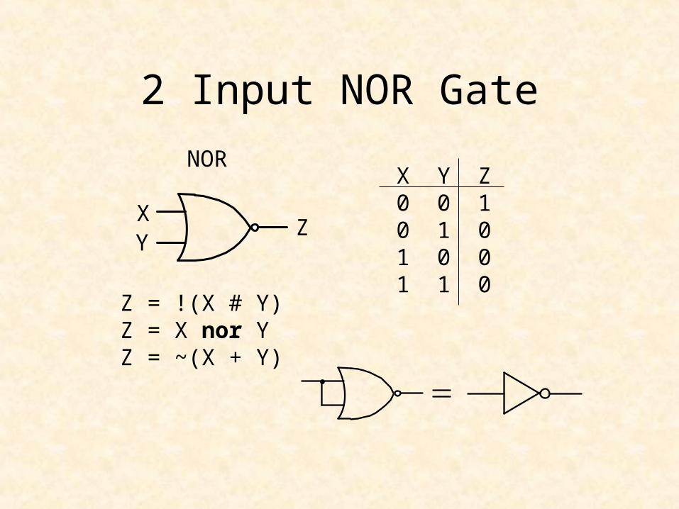
2 Input NOR Gate
NOR
XY
Z
Z = !(X # Y)Z = X nor YZ = ~(X + Y)
X Y Z0 0 10 1 01 0 01 1 0

NAND Gate
X
Y
X
Y
Z Z
Z = !(X & Y) Z = !X # !Y
=
X Y W Z0 0 0 10 1 0 11 0 0 11 1 1 0
X Y !X !Y Z0 0 1 1 10 1 1 0 11 0 0 1 11 1 0 0 0

De Morgan’s Theorem-1
!(X & Y) = !X # !Y
• NOT all variables• Change & to # and # to &• NOT the result

NOR Gate
X
YZ
Z = !(X # Y)
X Y Z0 0 10 1 01 0 01 1 0
X
YZ
Z = !X & !Y
X Y !X !Y Z0 0 1 1 10 1 1 0 01 0 0 1 01 1 0 0 0

De Morgan’s Theorem-2
!(X # Y) = !X & !Y
• NOT all variables• Change & to # and # to &• NOT the result
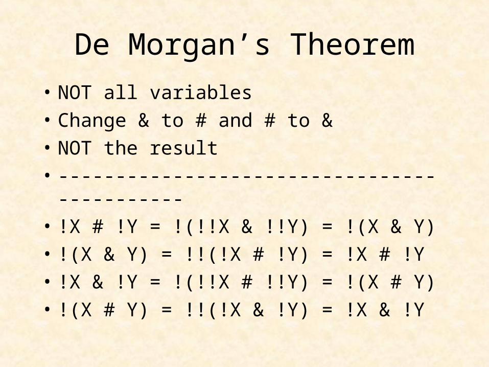
De Morgan’s Theorem
• NOT all variables
• Change & to # and # to &
• NOT the result
• --------------------------------------------
• !X # !Y = !(!!X & !!Y) = !(X & Y)
• !(X & Y) = !!(!X # !Y) = !X # !Y
• !X & !Y = !(!!X # !!Y) = !(X # Y)
• !(X # Y) = !!(!X & !Y) = !X & !Y
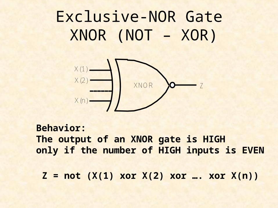
Exclusive-NOR Gate XNOR (NOT – XOR)
Behavior:The output of an XNOR gate is HIGH only if the number of HIGH inputs is EVEN
Z = not (X(1) xor X(2) xor …. xor X(n))
X(1)
X(2)
X(n)
ZXNOR
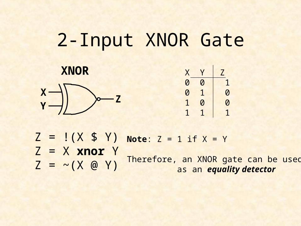
2-Input XNOR Gate
XNOR X Y Z0 0 10 1 01 0 01 1 1
Z = !(X $ Y)Z = X xnor YZ = ~(X @ Y)
Note: Z = 1 if X = Y
Therefore, an XNOR gate can be used as an equality detector
XY
Z
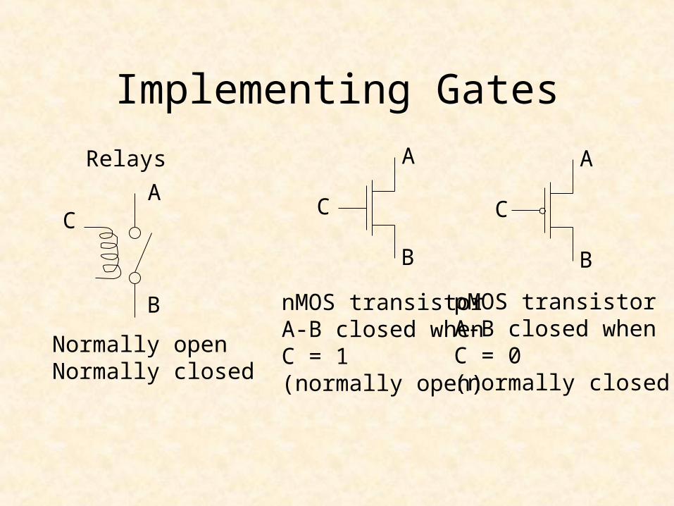
Implementing Gates
Relays
Normally openNormally closed
A
B
C
A
B
C
A
B
C
nMOS transistorA-B closed whenC = 1(normally open)
pMOS transistorA-B closed whenC = 0(normally closed)
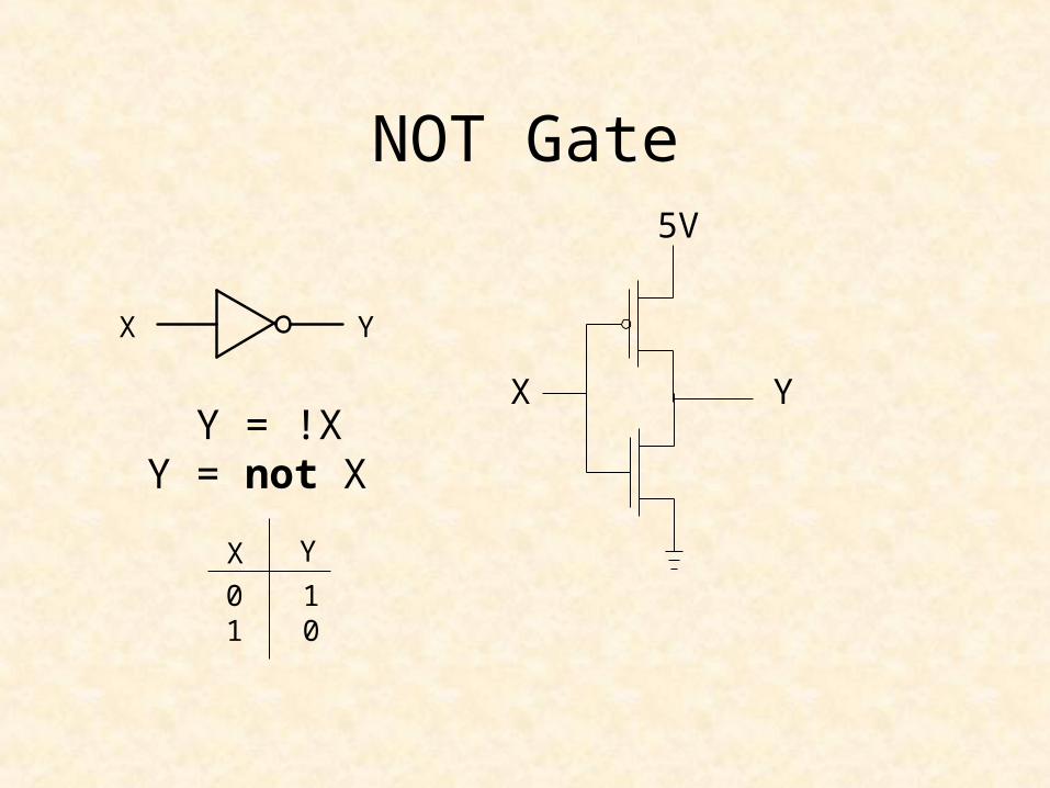
NOT Gate5V
X YY = !X
Y = not X
X Y
X Y
01
10
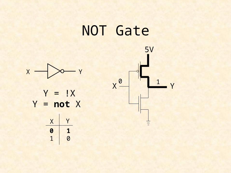
NOT Gate5V
X YY = !X
Y = not X
X Y
0 1
X Y
01
10
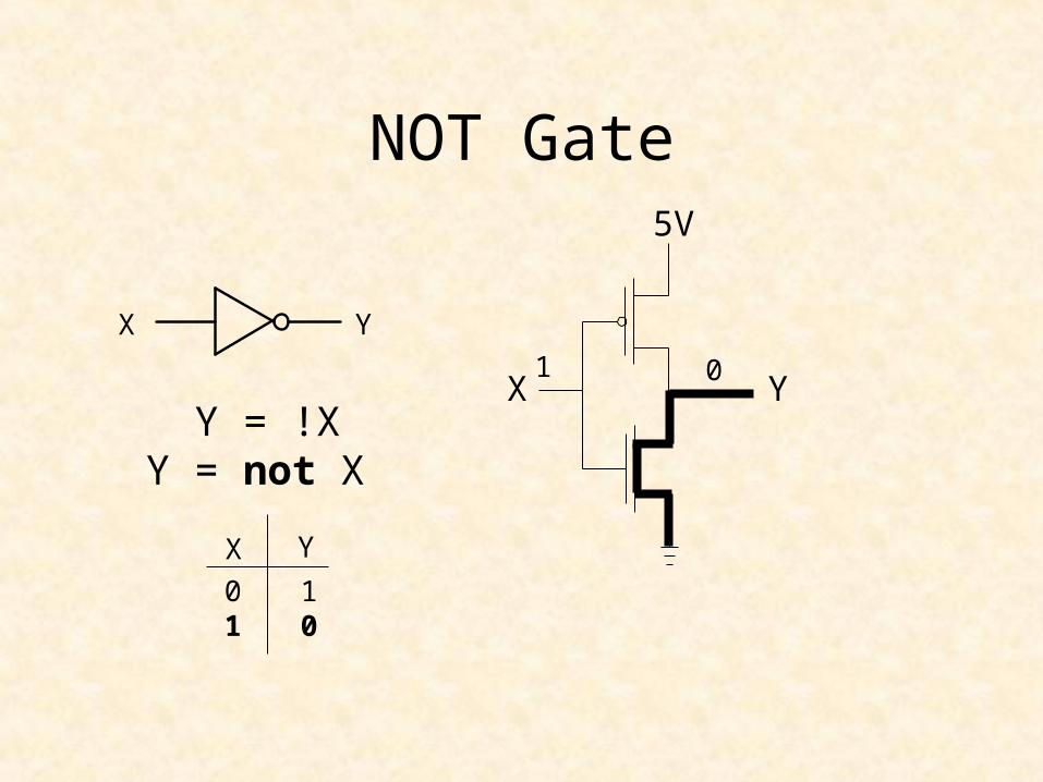
NOT Gate5V
X YY = !X
Y = not X
X Y
1 0
X Y
01
10

NAND Gate
X
Y
Z
5V
X
YZ
X Y Z0 0 10 1 11 0 11 1 0
NAND Gate
X
Y
Z
5V
X
YZ
X Y Z0 0 10 1 11 0 11 1 0
0
0

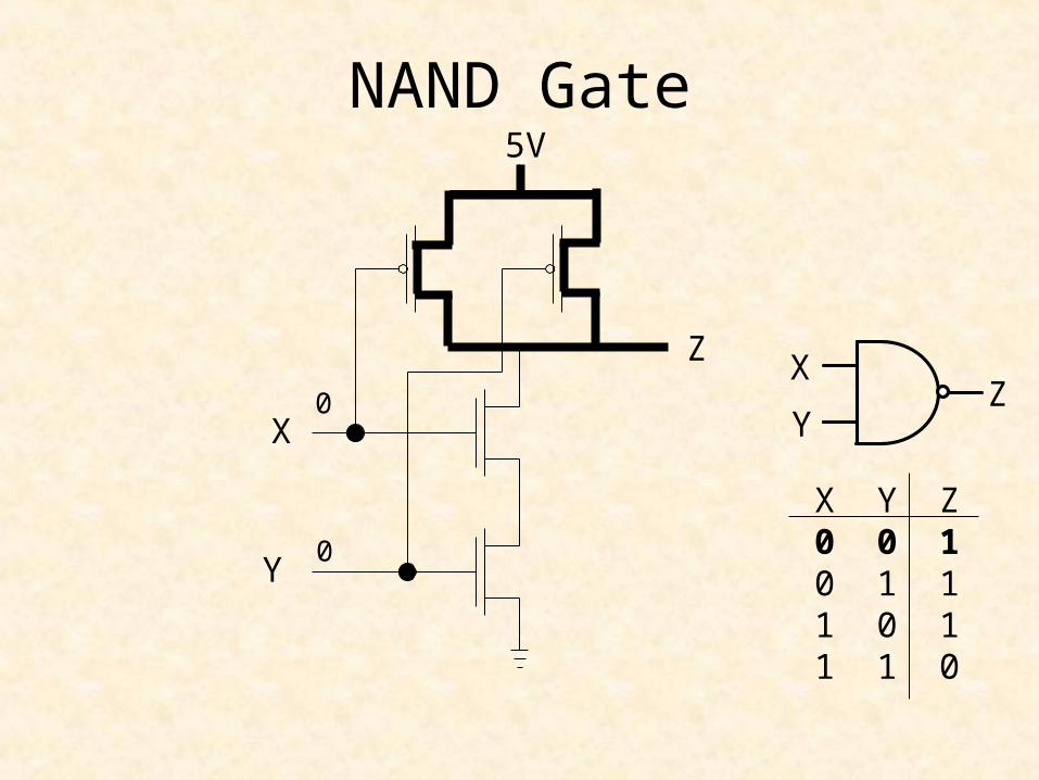
NAND Gate
X
Y
Z
5V
X
YZ
X Y Z0 0 10 1 11 0 11 1 0
0
1

NAND Gate
X
Y
Z
5V
X
YZ
X Y Z0 0 10 1 11 0 11 1 0
1
0
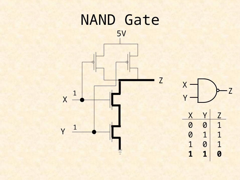
NAND Gate
X
Y
Z
5V
X
YZ
X Y Z0 0 10 1 11 0 11 1 0
1
1
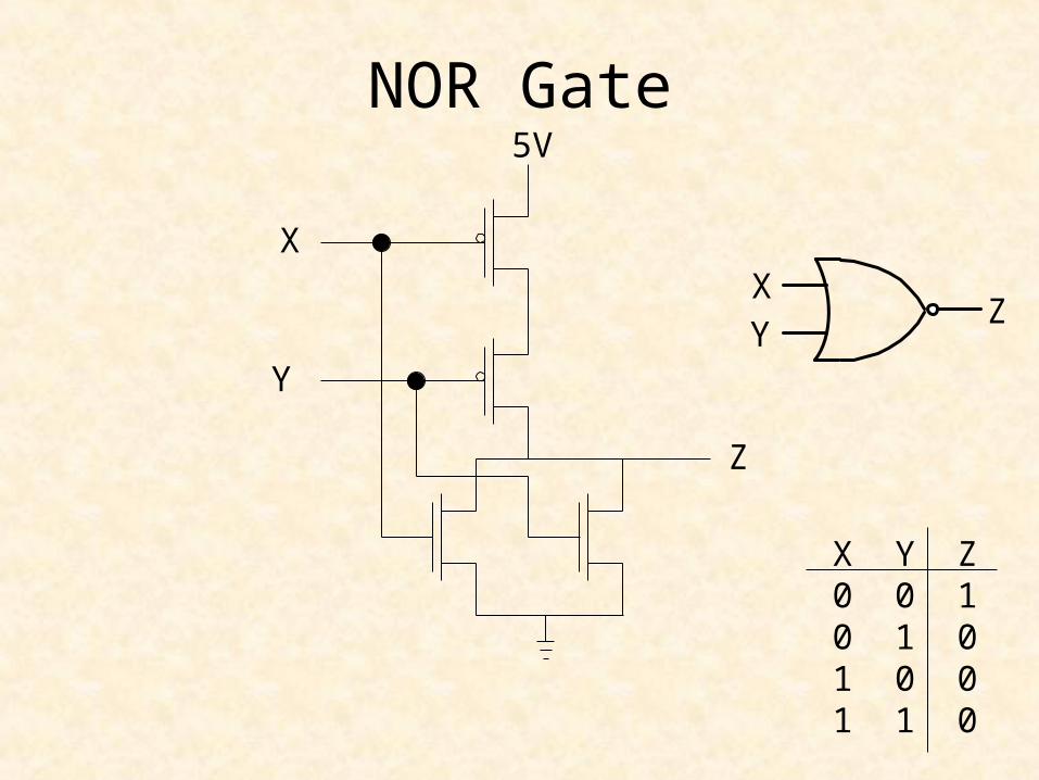
NOR Gate
X
Y
Z
5V
XY
Z
X Y Z0 0 10 1 01 0 01 1 0

NOR Gate
X
Y
Z
5V
XY
Z
X Y Z0 0 10 1 01 0 01 1 0
0
0

NOR Gate
X
Y
Z
5V
XY
Z
X Y Z0 0 10 1 01 0 01 1 0
0
1
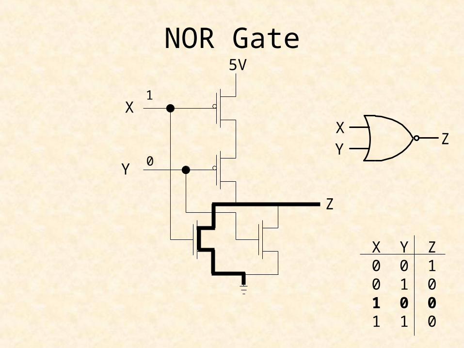
NOR Gate
X
Y
Z
5V
XY
Z
X Y Z0 0 10 1 01 0 01 1 0
1
0

NOR Gate
X
Y
Z
5V
XY
Z
X Y Z0 0 10 1 01 0 01 1 0
1
1

AND Gate
X
Y
5V
Z
5V
NAND-NOT

OR Gate
X
Y
5V
Z
5V
NOR-NOT
Top Related