


Languages
Pages
Legal

AS-CSZZZZ-MGE-00
KITO Chain Sling 100
Assembly Manual
For those assembling/disassembling the chain sling
● This manual is intended for those having expertise* and assembling the chain sling at KITO overseas
affiliates.
● When assembling new KITO Chain Sling 100, prepare KITO Chain Sling 100 Catalog (Revision No.
CSGE1508-01 in the upper right corner of the front page) in addition to this document.
● Those assembling the chain sling are requested to read and understand the information herein
without fail before work.
● Please read and understand the information in the Owner’s Manual as well.
* Personnel familiar with the structure and mechanism of the chain sling and certified to have expertise
by a business entity.
The chain sling, if assembled in a wrong manner, may cause danger such as falling of a suspended load. Those assembling the chain sling are requested to read and understand the information herein without fail before work. After reading, please keep this manual at hand so that you can read it anytime during assembly work.
This Assembly Manual classifies the precautions into two categories of “DANGER” and “CAUTION”.
: Indicates an imminently hazardous situation which, if not avoided, will result in death or serious injury.
: Indicates a potentially hazardous situation which, if not avoided, may result in minor or moderate injury.
Further, the event described in CAUTION may result in serious accident depending on the situation. Both DANGER and CAUTION describe important contents. Please follow the instruction.
means “Prohibited” or “You must not do”.
Prohibited action is shown in the circle or described near the circle.
This Assembly Manual uses as the general prohibition.
means “Mandatory Action” or “You must do”.
Required action is shown in the circle or described near the circle.
This Assembly Manual uses as the general instruction.
Description of Signal Words
Safety Precautions
Description of Safety Symbols
Prohibited
!
!
Mandatory
!
DANGER
CAUTION
DANGER
Prohibited ● Only those having expertise are allowed to assemble and disassemble the chain
sling.
Assembly and disassembly by unskilled personnel may result in death or serious injury.
Prohibited ● Use only KITO original parts for the chain sling.
KITO original parts may not be usable if their codes are different. Use correct parts
according to this manual.
Prohibited ● Do not disassemble and assemble the chain sling while it is suspended.
Be sure to disassemble and assemble the chain sling on a workbench.
Disassembly and assembly of the suspended chain sling may result in death or serious
injury.
Prohibited ● Do not cut, add or weld the sling chain.
Failure to comply with this instruction may result in death or serious injury.
Mandatory ● Once assembly work is completed, make sure that the chain sling has been
correctly assembled, and that the chain moves smoothly at the fitting connecting
part.
Failure to comply with this instruction may result in death or serious injury.
CAUTION
Mandatory ● When assembling the chain sling, observe the following.
▪ After disassembly, wipe and clean the parts reused.
Failure to comply with this instruction may result in damage on the properties such as a
broken chain sling or missing part.
Mandatory ● When reassembling, be sure to replace the following parts with new ones.
▪ Clevis-type spring pin
▪ Eye-type spring collar and protective collar
Failure to comply with this instruction may result in damage on the properties such as a
broken chain sling or missing part.
General Handling Precautions
1. Determination of Specifications・・・・・・・・・・・・・・・・・・・・・・・・・・・・・・・・・・・・・・・・・・・・・・・・・・・・・・・・・・ 1 2. Preparation of Components・・・・・・・・・・・・・・・・・・・・・・・・・・・・・・・・・・・・・・・・・・・・・・・・・・・・・・・・・・・・・ 1
2-1 Selecting the Working Load Limit and Chain Diameter・・・・・・・・・・・・・・・・・・・・・・・・・・・・・・・・・ 1 2-2 Preparing the Components (Hook, Fitting, etc.) ・・・・・・・・・・・・・・・・・・・・・・・・・・・・・・・・・・・・・・ 4 2-3 Determining the Chain Length・・・・・・・・・・・・・・・・・・・・・・・・・・・・・・・・・・・・・・・・・・・・・・・・・・・・・・・ 4
3. Assembly Procedures・・・・・・・・・・・・・・・・・・・・・・・・・・・・・・・・・・・・・・・・・・・・・・・・・・・・・・・・・・・・・・・・・・ 6 3-1 Common Matters to Clevis Type and Eye Type・・・・・・・・・・・・・・・・・・・・・・・・・・・・・・・・・・・・・・・ 6 3-2 Clevis Type・・・・・・・・・・・・・・・・・・・・・・・・・・・・・・・・・・・・・・・・・・・・・・・・・・・・・・・・・・・・・・・・・・・・・・・・ 7 3-3 Eye Type・・・・・・・・・・・・・・・・・・・・・・・・・・・・・・・・・・・・・・・・・・・・・・・・・・・・・・・・・・・・・・・・・・・・・・・・・・ 8
4. List of Required Chain Length and Required Components for Standard Sling Types・・・・・・・・・・ 9 4-1 Precautions for Clevis Type・・・・・・・・・・・・・・・・・・・・・・・・・・・・・・・・・・・・・・・・・・・・・・・・・・・・・・・・・ 9 4-2 Precautions for Eye Type・・・・・・・・・・・・・・・・・・・・・・・・・・・・・・・・・・・・・・・・・・・・・・・・・・・・・・・・・・・10 4-3 List of Required Chain Length and Required Components for Standard Sling Types・・・・・・12
4-3-1 Clevis-type Single-leg Sling・・・・・・・・・・・・・・・・・・・・・・・・・・・・・・・・・・・・・・・・・・・・・・・・・・・12 4-3-2 Clevis-type Double-leg Sling・・・・・・・・・・・・・・・・・・・・・・・・・・・・・・・・・・・・・・・・・・・・・・・・・・14 4-3-3 Clevis-type Triple-leg Sling・・・・・・・・・・・・・・・・・・・・・・・・・・・・・・・・・・・・・・・・・・・・・・・・・・・ 15 4-3-4 Clevis-type Quadruple-leg Sling・・・・・・・・・・・・・・・・・・・・・・・・・・・・・・・・・・・・・・・・・・・・・・・16 4-3-5 Eye-type Single-leg Sling・・・・・・・・・・・・・・・・・・・・・・・・・・・・・・・・・・・・・・・・・・・・・・・・・・・・・17 4-3-6 Eye-type Double-leg Sling・・・・・・・・・・・・・・・・・・・・・・・・・・・・・・・・・・・・・・・・・・・・・・・・・・・・18 4-3-7 Eye-type Triple-leg Sling・・・・・・・・・・・・・・・・・・・・・・・・・・・・・・・・・・・・・・・・・・・・・・・・・・・・・ 19 4-3-8 Eye-type Quadruple-leg Sling・・・・・・・・・・・・・・・・・・・・・・・・・・・・・・・・・・・・・・・・・・・・・・・・・20 4-3-9 Eye-type Triple-leg Sling with Master Link with Sub Links・・・・・・・・・・・・・・・・・・・・・・・・21 4-3-10 Eye-type Quadruple-leg Sling with Master Link with Sub Links・・・・・・・・・・・・・・・・・・22 4-3-11 Eye-type Single-leg Sling with Large Master Link・・・・・・・・・・・・・・・・・・・・・・・・・・・・・・23 4-3-12 Eye-type Double-leg Sling with Large Master Link・・・・・・・・・・・・・・・・・・・・・・・・・・・・・24 4-3-13 Eye-type Triple-leg Sling with Large Master Link・・・・・・・・・・・・・・・・・・・・・・・・・・・・・・ 25 4-3-14 Eye-type Quadruple-leg Sling with Large Master Link・・・・・・・・・・・・・・・・・・・・・・・・・・26
● When assembling the chain sling, be sure to prepare “KITO Chain Sling 100 Catalog
(Revision No. CSGE1508-01 in the upper right corner of the front page).
Table of Contents
1
1. Determination of Specifications
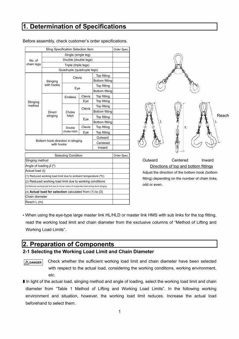
Before assembly, check customer’s order specifications.
▪ When using the eye-type large master link HL/HLD or master link HMS with sub links for the top fitting,
read the working load limit and chain diameter from the exclusive columns of “Method of Lifting and
Working Load Limits”.
2. Preparation of Components 2-1 Selecting the Working Load Limit and Chain Diameter
Check whether the sufficient working load limit and chain diameter have been selected
with respect to the actual load, considering the working conditions, working environment,
etc.
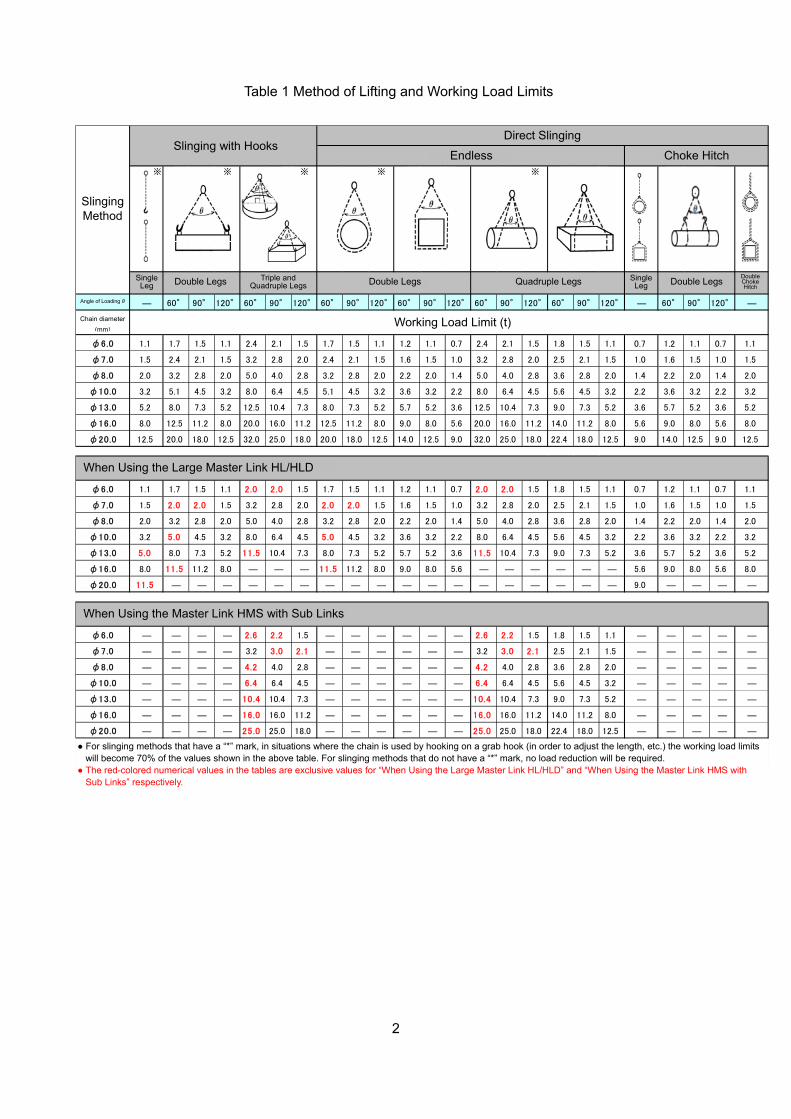
■ In light of the actual load, slinging method and angle of loading, select the working load limit and chain
diameter from “Table 1 Method of Lifting and Working Load Limits”. In the following working
environment and situation, however, the working load limit reduces. Increase the actual load
beforehand to select them.
Outward Centered Inward
Directions of top and bottom fittings
Adjust the direction of the bottom hook (bottom
fitting) depending on the number of chain links,
odd or even.
受注仕様
ウエカナグ
シタカナグ
ウエカナグ
シタカナグ
ピン ウエカナグ
アイ ウエカナグ
ウエカナグ
シタカナグ
ウエカナグ
シタカナグ
ピン ウエカナグ
アイ ウエカナグ
外向き
中向き
内向き
受注仕様
アイ
カナグ掛けでのシタフックの向き
2本でチョーク
スリング仕様の選択項目
選定条件
じか巻き掛け
シングル(1本つり)
ダブル(2本つり)
トリプル(3本つり)
ピン
アイ
ピン
バスケットつり
① 周囲温度(℃)による使用荷重の低減
リーチL(m)
つり方
カナグ掛け
実荷重(t)
つり角度β(°)
クウォード(4本つり)
② 作業条件による使用荷重の低減
③ じか巻き掛け時のつり荷の角部Rによる使用荷重の低減
④ ①~③より算出した選定用の実荷重
チェーン線径
つり方
チェーンの本数
チョークつり Reach
Sling Specification Selection Item
No. of chain legs
Order Spec.
Single (single leg)
Double (double legs)
Triple (triple legs)
Quadruple (quadruple legs)
Slinging method
Clevis
Direct slinging
Slinging with hooks
Eye
Double choke hitch
Choke hitch
Endless Clevis
Clevis
Clevis
Eye
Eye
Eye
Bottom hook direction in slingingwith hooks
Outward
Inward
Centered
Top fitting
Bottom fitting
Top fitting
Top fitting
Top fitting
Top fitting
Top fitting
Top fitting
Top fitting
Bottom fitting
Bottom fitting
Bottom fitting
Selecting Condition Order Spec.
Slinging method
Angle of loading β (º)
Actual load (t)
(1) Reduced working load limit due to ambient temperature (ºC)
(2) Reduced working load limit due to working conditions
(3) Reduced working load limit due to corner radius of suspended load during direct slinging
Chain diameter
Reach L (m)
(4) Actual load for selection calculated from (1) to (3)
DANGER
2
※ ※ ※ ※ ※
1本つり 1本つり2本で
チョーク
つり角度θ ― 60° 90° 120° 60° 90° 120° 60° 90° 120° 60° 90° 120° 60° 90° 120° 60° 90° 120° ― 60° 90° 120° ―
チェーン線径(mm)
φ6.0 1.1 1.7 1.5 1.1 2.4 2.1 1.5 1.7 1.5 1.1 1.2 1.1 0.7 2.4 2.1 1.5 1.8 1.5 1.1 0.7 1.2 1.1 0.7 1.1
φ7.0 1.5 2.4 2.1 1.5 3.2 2.8 2.0 2.4 2.1 1.5 1.6 1.5 1.0 3.2 2.8 2.0 2.5 2.1 1.5 1.0 1.6 1.5 1.0 1.5
φ8.0 2.0 3.2 2.8 2.0 5.0 4.0 2.8 3.2 2.8 2.0 2.2 2.0 1.4 5.0 4.0 2.8 3.6 2.8 2.0 1.4 2.2 2.0 1.4 2.0
φ10.0 3.2 5.1 4.5 3.2 8.0 6.4 4.5 5.1 4.5 3.2 3.6 3.2 2.2 8.0 6.4 4.5 5.6 4.5 3.2 2.2 3.6 3.2 2.2 3.2
φ13.0 5.2 8.0 7.3 5.2 12.5 10.4 7.3 8.0 7.3 5.2 5.7 5.2 3.6 12.5 10.4 7.3 9.0 7.3 5.2 3.6 5.7 5.2 3.6 5.2
φ16.0 8.0 12.5 11.2 8.0 20.0 16.0 11.2 12.5 11.2 8.0 9.0 8.0 5.6 20.0 16.0 11.2 14.0 11.2 8.0 5.6 9.0 8.0 5.6 8.0
φ20.0 12.5 20.0 18.0 12.5 32.0 25.0 18.0 20.0 18.0 12.5 14.0 12.5 9.0 32.0 25.0 18.0 22.4 18.0 12.5 9.0 14.0 12.5 9.0 12.5
φ6.0 1.1 1.7 1.5 1.1 2.0 2.0 1.5 1.7 1.5 1.1 1.2 1.1 0.7 2.0 2.0 1.5 1.8 1.5 1.1 0.7 1.2 1.1 0.7 1.1
φ7.0 1.5 2.0 2.0 1.5 3.2 2.8 2.0 2.0 2.0 1.5 1.6 1.5 1.0 3.2 2.8 2.0 2.5 2.1 1.5 1.0 1.6 1.5 1.0 1.5
φ8.0 2.0 3.2 2.8 2.0 5.0 4.0 2.8 3.2 2.8 2.0 2.2 2.0 1.4 5.0 4.0 2.8 3.6 2.8 2.0 1.4 2.2 2.0 1.4 2.0
φ10.0 3.2 5.0 4.5 3.2 8.0 6.4 4.5 5.0 4.5 3.2 3.6 3.2 2.2 8.0 6.4 4.5 5.6 4.5 3.2 2.2 3.6 3.2 2.2 3.2
φ13.0 5.0 8.0 7.3 5.2 11.5 10.4 7.3 8.0 7.3 5.2 5.7 5.2 3.6 11.5 10.4 7.3 9.0 7.3 5.2 3.6 5.7 5.2 3.6 5.2
φ16.0 8.0 11.5 11.2 8.0 ― ― ― 11.5 11.2 8.0 9.0 8.0 5.6 ― ― ― ― ― ― 5.6 9.0 8.0 5.6 8.0
φ20.0 11.5 ― ― ― ― ― ― ― ― ― ― ― ― ― ― ― ― ― ― 9.0 ― ― ― ―
φ6.0 ― ― ― ― 2.6 2.2 1.5 ― ― ― ― ― ― 2.6 2.2 1.5 1.8 1.5 1.1 ― ― ― ― ―
φ7.0 ― ― ― ― 3.2 3.0 2.1 ― ― ― ― ― ― 3.2 3.0 2.1 2.5 2.1 1.5 ― ― ― ― ―
φ8.0 ― ― ― ― 4.2 4.0 2.8 ― ― ― ― ― ― 4.2 4.0 2.8 3.6 2.8 2.0 ― ― ― ― ―
φ10.0 ― ― ― ― 6.4 6.4 4.5 ― ― ― ― ― ― 6.4 6.4 4.5 5.6 4.5 3.2 ― ― ― ― ―
φ13.0 ― ― ― ― 10.4 10.4 7.3 ― ― ― ― ― ― 10.4 10.4 7.3 9.0 7.3 5.2 ― ― ― ― ―
φ16.0 ― ― ― ― 16.0 16.0 11.2 ― ― ― ― ― ― 16.0 16.0 11.2 14.0 11.2 8.0 ― ― ― ― ―
φ20.0 ― ― ― ― 25.0 25.0 18.0 ― ― ― ― ― ― 25.0 25.0 18.0 22.4 18.0 12.5 ― ― ― ― ―
使 用 荷 重 (t)
大型マスターリンクHL/HLD使用時
サブリンク付マスターリンクHMS使用時
つり方
カナグ掛けじか巻掛け
バスケットつり チョークつり
2本つり 3本つり、4本つり 2本つり 4本つり 2本つり
Slinging Method
Angle of Loading θ
Chain diameter
(mm)
Single Leg Double Legs Triple and
Quadruple Legs
Working Load Limit (t)
Double Legs Quadruple Legs
Endless Choke Hitch
When Using the Large Master Link HL/HLD
When Using the Master Link HMS with Sub Links
● For slinging methods that have a “*” mark, in situations where the chain is used by hooking on a grab hook (in order to adjust the length, etc.) the working load limits will become 70% of the values shown in the above table. For slinging methods that do not have a “*” mark, no load reduction will be required.
● The red-colored numerical values in the tables are exclusive values for “When Using the Large Master Link HL/HLD” and “When Using the Master Link HMS with Sub Links” respectively.
Double LegsSingle Leg
Double Choke Hitch
Slinging with Hooks Direct Slinging
Table 1 Method of Lifting and Working Load Limits
3
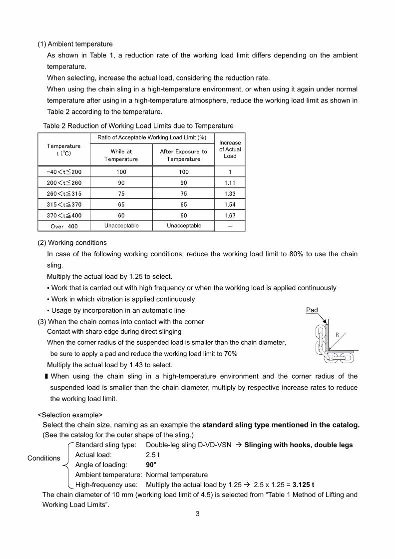
(1) Ambient temperature
As shown in Table 1, a reduction rate of the working load limit differs depending on the ambient
temperature.
When selecting, increase the actual load, considering the reduction rate.
When using the chain sling in a high-temperature environment, or when using it again under normal
temperature after using in a high-temperature atmosphere, reduce the working load limit as shown in
Table 2 according to the temperature.
While atTemperature
After Exposure toTemperature
-40<t≦200 100 100 1
200<t≦260 90 90 1.11
260<t≦315 75 75 1.33
315<t≦370 65 65 1.54
370<t≦400 60 60 1.67
Over 400 使用不可 使用不可 -
Temperaturet (℃)
使用可能な使用荷重の割合(%)実荷重の増加
(2) Working conditions
In case of the following working conditions, reduce the working load limit to 80% to use the chain
sling.
Multiply the actual load by 1.25 to select.
▪ Work that is carried out with high frequency or when the working load is applied continuously
▪ Work in which vibration is applied continuously
▪ Usage by incorporation in an automatic line
(3) When the chain comes into contact with the corner Contact with sharp edge during direct slinging
When the corner radius of the suspended load is smaller than the chain diameter,
be sure to apply a pad and reduce the working load limit to 70%
Multiply the actual load by 1.43 to select.
■ When using the chain sling in a high-temperature environment and the corner radius of the
suspended load is smaller than the chain diameter, multiply by respective increase rates to reduce
the working load limit.
<Selection example>
Select the chain size, naming as an example the standard sling type mentioned in the catalog.
(See the catalog for the outer shape of the sling.)
Standard sling type: Double-leg sling D-VD-VSN Slinging with hooks, double legs
Actual load: 2.5 t
Angle of loading: 90°
Ambient temperature: Normal temperature
High-frequency use: Multiply the actual load by 1.25 2.5 x 1.25 = 3.125 t
The chain diameter of 10 mm (working load limit of 4.5) is selected from “Table 1 Method of Lifting and
Working Load Limits”.
Conditions
Table 2 Reduction of Working Load Limits due to Temperature
Ratio of Acceptable Working Load Limit (%) Increase of Actual
Load
Unacceptable Unacceptable
Pad

4
PP
Reach L
2-2 Preparing the Components (Hook, Fitting, etc.)
■ Select the top and bottom fittings based on the chain diameter and number of chain legs in line with
the customer’s order specifications.
■ In case of the standard sling type in the catalog, select the required components, seeing
“Chapter 4. List of Required Chain Length and Required Components for Standard Sling
Types”.
■ A chain pin kit is enclosed in the same package as the fittings and hooks.
<Selection example> In case of the standard sling type, type D-VD-VSS/Q-VD-VSS/Q-HM-HTS, chain
diameter = 8 mm
(See the catalog for the outer shape of the sling.)
Clevis-type D-VD-VSN Clevis-type Q-VD-VSN Eye-type Q-HM-HTN
2-3 Determining the Chain Length
Cut the chain with a high-speed cutting machine or a chain cutter.
2-3-1 Calculating the Standard Sling Type
■ See “Chapter 4. List of Required Chain Length and Required Components for Standard
Sling Types”.
See the catalog for the P-dimension of the fittings components.
(1) Clevis type
Reach L dimension – Top fitting P dimension – Bottom fitting P dimension = Required chain length
Required chain length / Selected chain pitch = No. of links
<Selection example> In case of type S-VE-V, chain diameter = 6 mm, reach L = 2.0 m
2000 – 115 – 115 = 1770 mm
1770/18.0 = 98.3 links No. of required links = 99
▪ Round up the chain length so that it will not be shorter than
the reach L dimension.
▪ For the sum of P dimension of the fittings components and the chain pitch, see “Chapter 4. List of
Required Chain Length and Required Components for Standard Sling Types”.
Clevis master link VD (VD20807), 1 pc.
Sling hook VSL2 (VSL2080), 2 pcs.
* Chain pin kit (VP2080K), 4 pcs.
Clevis master link VD (VD21008), 1 pc.
Dual connector VB (VB2080), 2 pcs.
Sling hook VSL2 (VSL2080), 4 pcs.
Chain pin kit (VP2080K), 8 pcs.
* Chain pin kit (VP2100K), 2 pcs.
Master link HMS (HMS2080), 1 pc.
Sling hook HTL2 (HTL2080), 4 pcs.
Hi-coupling HC (HC2080), 8 pcs.
Top fitting Bottom fitting
CAUTION
5
Reach L
PP P P
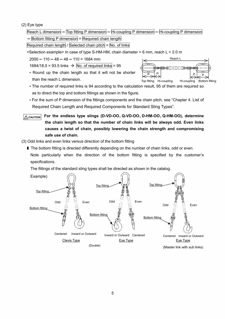
(2) Eye type
Reach L dimension – Top fitting P dimension – Hi-coupling P dimension – Hi-coupling P dimension
– Bottom fitting P dimension = Required chain length
Required chain length / Selected chain pitch = No. of links
<Selection example> In case of type S-HM-HM, chain diameter = 6 mm, reach L = 2.0 m
2000 – 110 – 48 – 48 – 110 = 1684 mm
1684/18.0 = 93.5 links No. of required links = 95
▪ Round up the chain length so that it will not be shorter
than the reach L dimension.
▪ The number of required links is 94 according to the calculation result, 95 of them are required so
as to direct the top and bottom fittings as shown in the figure.
▪ For the sum of P dimension of the fittings components and the chain pitch, see “Chapter 4. List of
Required Chain Length and Required Components for Standard Sling Types”.
For the endless type slings (D-VD-OO、Q-VD-OO、D-HM-OO、Q-HM-OO), determine
the chain length so that the number of chain links will be always odd. Even links
causes a twist of chain, possibly lowering the chain strength and compromising
safe use of chain.
(3) Odd links and even links versus direction of the bottom fitting
■ The bottom fitting is directed differently depending on the number of chain links, odd or even.
Note particularly when the direction of the bottom fitting is specified by the customer’s
specifications.
The fittings of the standard sling types shall be directed as shown in the catalog.
Example)
Top fitting Bottom fittingHi-coupling Hi-coupling
(Double)
ウエカナグ
シタカナグ
奇数 偶数
奇数 偶数
中 内 or 外
Odd Even
Bottom fitting
Even Odd
Top fitting
Clevis Type Eye Type
Centered Inward or Outward Inward or Outward Centered
Bottom fitting
Top fitting Top fitting
Eye Type
(Master link with sub links)
Even Odd
Bottom fitting
Centered Inward or Outward
CAUTION
6
3. Assembly Procedures
Wrong assembly may result in death or serious injury.
Observe the assembly procedures to assemble the chain sling correctly.
3-1 Common Matters to Clevis Type and Eye Type 3-1-1 Marking on the Sling Tag
Upon receiving an order, be sure to check the slinging method and angle of loading,
mark on the sling tag the working load limit determined according to Table 1 Method
of Lifting and Working Load Limits, Reduction of Working Load Limits due to
Temperature Table 2, reduction due to the working conditions, and corner radius
versus chain diameter on Pages 2 to 3.
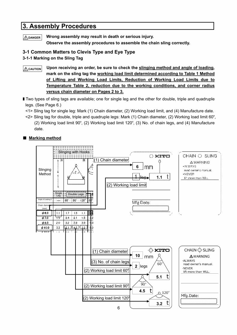
■ Two types of sling tags are available; one for single leg and the other for double, triple and quadruple
legs. (See Page 6.)
<1> Sling tag for single leg: Mark (1) Chain diameter, (2) Working load limit, and (4) Manufacture date.
<2> Sling tag for double, triple and quadruple legs: Mark (1) Chain diameter, (2) Working load limit 60º, (2) Working load limit 90º, (2) Working load limit 120º, (3) No. of chain legs, and (4) Manufacture
date.
■ Marking method
6
1.1
(1) Chain diameter
(2) Working load limit
10
2
5.1
4.5
3.2
(2) Working load limit 60º
(2) Working load limit 90º
(2) Working load limit 120º
(3) No. of chain legs
(1) Chain diameter
Slinging with Hooks
Slinging Method
Angle of Loading θ
Chain diameter
(mm)
Single Leg Double Legs
CAUTION
DANGER
7
Sling tag
attaching
position
Spring pin
Chain pin
Sling hookClevis master link
Spring pin
Chain pin Hook or fitting
Spring pin hole
Chain
Spring pin
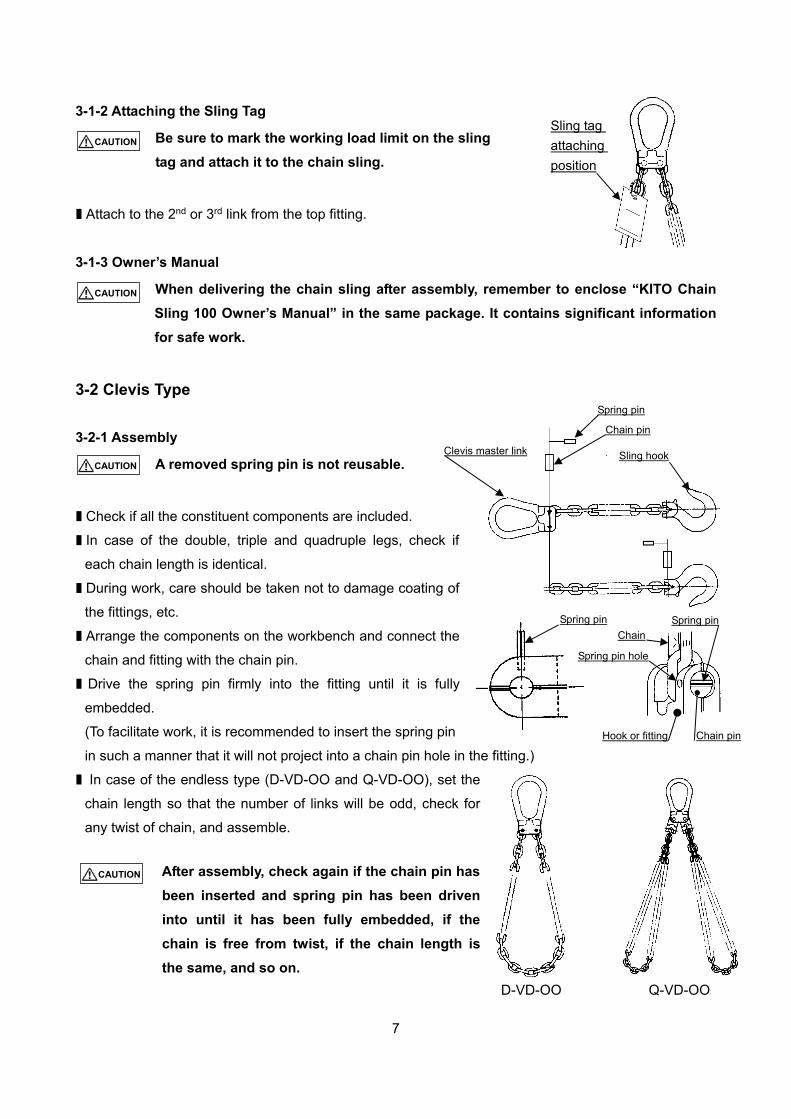
3-1-2 Attaching the Sling Tag
Be sure to mark the working load limit on the sling
tag and attach it to the chain sling.
■ Attach to the 2nd or 3rd link from the top fitting.
3-1-3 Owner’s Manual
When delivering the chain sling after assembly, remember to enclose “KITO Chain
Sling 100 Owner’s Manual” in the same package. It contains significant information
for safe work.
3-2 Clevis Type
3-2-1 Assembly
A removed spring pin is not reusable.
■ Check if all the constituent components are included.
■ In case of the double, triple and quadruple legs, check if
each chain length is identical.
■ During work, care should be taken not to damage coating of
the fittings, etc.
■ Arrange the components on the workbench and connect the
chain and fitting with the chain pin.
■ Drive the spring pin firmly into the fitting until it is fully
embedded.
(To facilitate work, it is recommended to insert the spring pin
in such a manner that it will not project into a chain pin hole in the fitting.)
■ In case of the endless type (D-VD-OO and Q-VD-OO), set the
chain length so that the number of links will be odd, check for
any twist of chain, and assemble.
After assembly, check again if the chain pin has
been inserted and spring pin has been driven
into until it has been fully embedded, if the
chain is free from twist, if the chain length is
the same, and so on.
D-VD-OO Q-VD-OO
CAUTION
CAUTION
CAUTION
CAUTION
8
Sling hook HTL Master link HM
Hi-coupling
Fitting pin
Protective collar
Spring collar
U-shaped fitting Fitting pin
Protective collar Spring collar
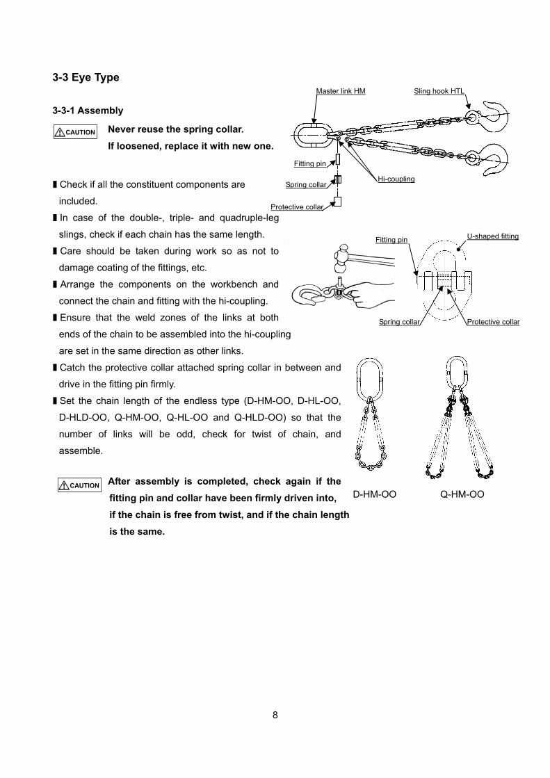
3-3 Eye Type
3-3-1 Assembly
Never reuse the spring collar.
If loosened, replace it with new one.
■ Check if all the constituent components are
included.
■ In case of the double-, triple- and quadruple-leg
slings, check if each chain has the same length.
■ Care should be taken during work so as not to
damage coating of the fittings, etc.
■ Arrange the components on the workbench and
connect the chain and fitting with the hi-coupling.
■ Ensure that the weld zones of the links at both
ends of the chain to be assembled into the hi-coupling
are set in the same direction as other links.
■ Catch the protective collar attached spring collar in between and
drive in the fitting pin firmly.
■ Set the chain length of the endless type (D-HM-OO, D-HL-OO,
D-HLD-OO, Q-HM-OO, Q-HL-OO and Q-HLD-OO) so that the
number of links will be odd, check for twist of chain, and
assemble.
After assembly is completed, check again if the
fitting pin and collar have been firmly driven into,
if the chain is free from twist, and if the chain length
is the same.
D-HM-OO Q-HM-OO
CAUTION
CAUTION
9
4. List of Required Chain Length and Required Components for Standard Sling Types
The following tables list the required chain length and required components for assembly of the
standard sling types mentioned in the catalog.
* For the P-dimension of the fittings components, see the catalog.
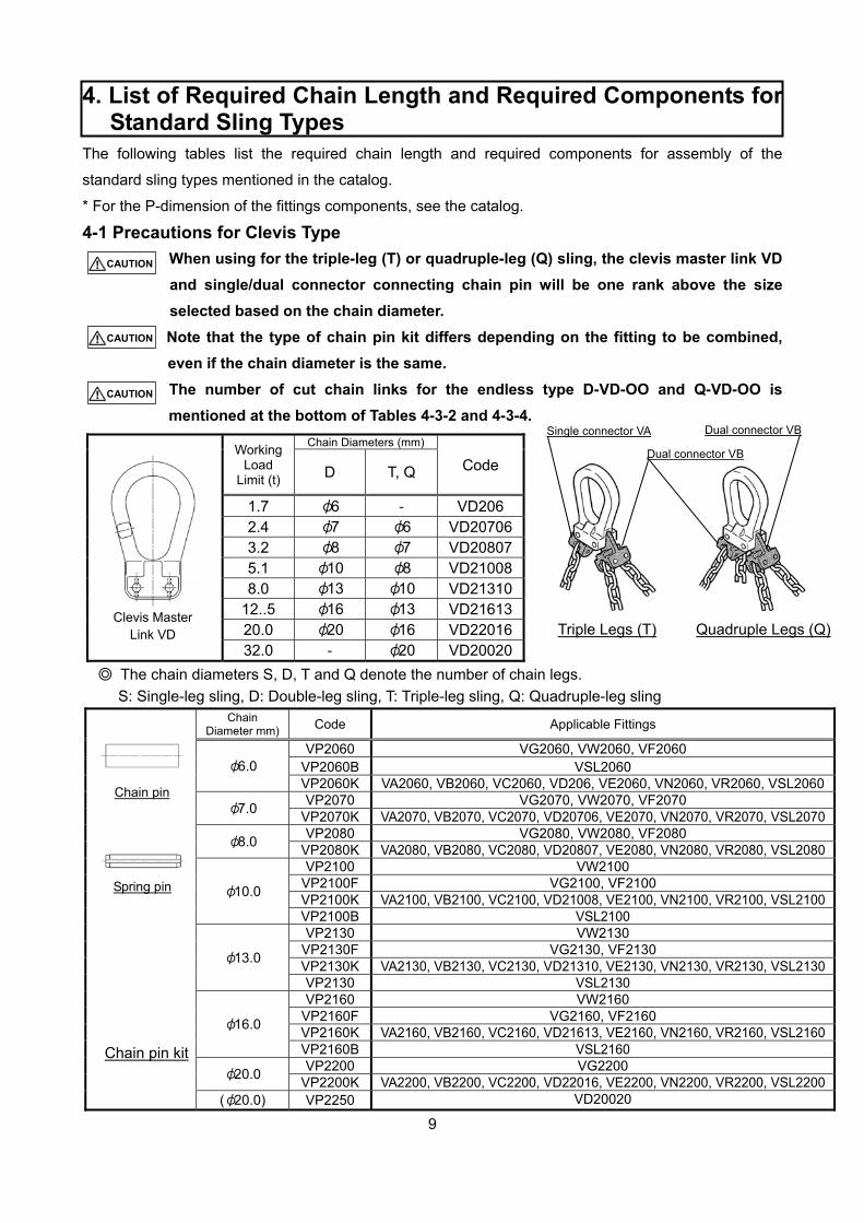
4-1 Precautions for Clevis Type
When using for the triple-leg (T) or quadruple-leg (Q) sling, the clevis master link VD
and single/dual connector connecting chain pin will be one rank above the size
selected based on the chain diameter.
Note that the type of chain pin kit differs depending on the fitting to be combined,
even if the chain diameter is the same.
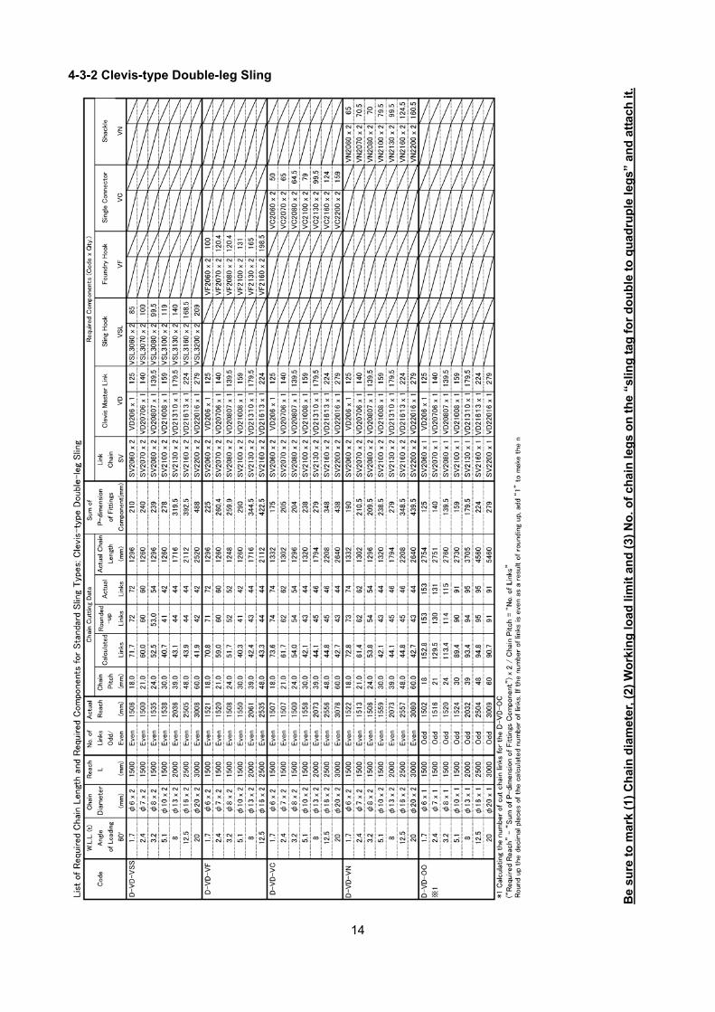
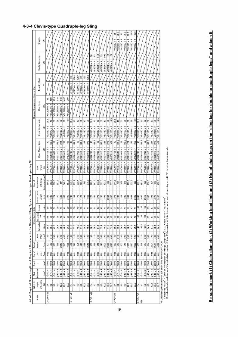
The number of cut chain links for the endless type D-VD-OO and Q-VD-OO is
mentioned at the bottom of Tables 4-3-2 and 4-3-4.
Working Load
Limit (t)
Chain Diameters (mm)
Code D T, Q
1.7 φ6 ‐ VD206 2.4 φ7 φ6 VD207063.2 φ8 φ7 VD208075.1 φ10 φ8 VD210088.0 φ13 φ10 VD21310
12..5 φ16 φ13 VD2161320.0 φ20 φ16 VD2201632.0 ‐ φ20 VD20020
◎ The chain diameters S, D, T and Q denote the number of chain legs.
S: Single-leg sling, D: Double-leg sling, T: Triple-leg sling, Q: Quadruple-leg sling
Clevis Master
Link VD
Triple Legs (T)
Quadruple Legs (Q)
Single connector VA
Dual connector VB
Dual connector VB
Chain Diameter mm) Code Applicable Fittings
φ6.0 VP2060 VG2060, VW2060, VF2060
VP2060B VSL2060 VP2060K VA2060, VB2060, VC2060, VD206, VE2060, VN2060, VR2060, VSL2060
φ7.0 VP2070 VG2070, VW2070, VF2070
VP2070K VA2070, VB2070, VC2070, VD20706, VE2070, VN2070, VR2070, VSL2070
φ8.0 VP2080 VG2080, VW2080, VF2080
VP2080K VA2080, VB2080, VC2080, VD20807, VE2080, VN2080, VR2080, VSL2080
φ10.0
VP2100 VW2100 VP2100F VG2100, VF2100 VP2100K VA2100, VB2100, VC2100, VD21008, VE2100, VN2100, VR2100, VSL2100VP2100B VSL2100
φ13.0
VP2130 VW2130 VP2130F VG2130, VF2130 VP2130K VA2130, VB2130, VC2130, VD21310, VE2130, VN2130, VR2130, VSL2130VP2130 VSL2130
φ16.0
VP2160 VW2160 VP2160F VG2160, VF2160 VP2160K VA2160, VB2160, VC2160, VD21613, VE2160, VN2160, VR2160, VSL2160VP2160B VSL2160
φ20.0 VP2200 VG2200
VP2200K VA2200, VB2200, VC2200, VD22016, VE2200, VN2200, VR2200, VSL2200(φ20.0) VP2250 VD20020
Chain pin kit
Spring pin
Chain pin
CAUTION
CAUTION
CAUTION
10
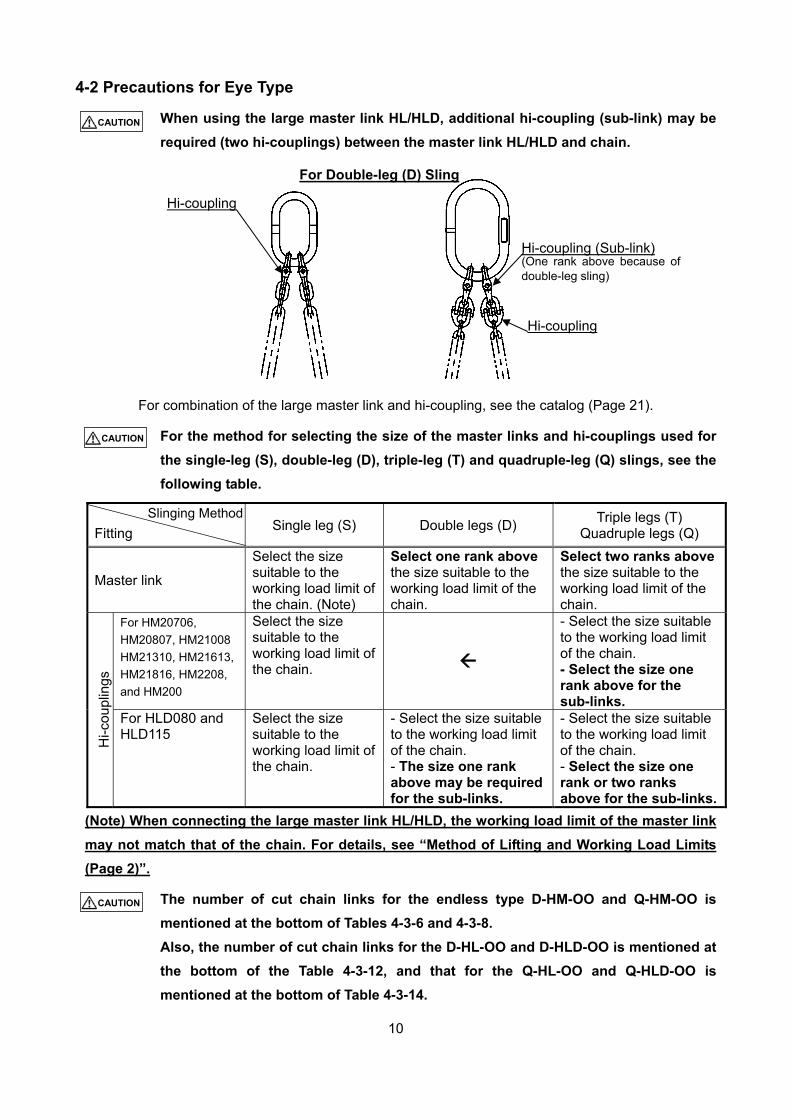
4-2 Precautions for Eye Type
When using the large master link HL/HLD, additional hi-coupling (sub-link) may be
required (two hi-couplings) between the master link HL/HLD and chain.
For combination of the large master link and hi-coupling, see the catalog (Page 21).
For the method for selecting the size of the master links and hi-couplings used for
the single-leg (S), double-leg (D), triple-leg (T) and quadruple-leg (Q) slings, see the
following table.
Fitting
Single leg (S) Double legs (D) Triple legs (T)
Quadruple legs (Q)
Master link
Select the size suitable to the working load limit of the chain. (Note)
Select one rank above the size suitable to the working load limit of the chain.
Select two ranks above the size suitable to the working load limit of the chain.
Hi-c
oupl
ings
For HM20706,
HM20807, HM21008
HM21310, HM21613,
HM21816, HM2208,
and HM200
Select the size suitable to the working load limit of the chain.
- Select the size suitable to the working load limit of the chain. - Select the size one rank above for the sub-links.
For HLD080 and HLD115
Select the size suitable to the working load limit of the chain.
- Select the size suitable to the working load limit of the chain. - The size one rank above may be required for the sub-links.
- Select the size suitable to the working load limit of the chain. - Select the size one rank or two ranks above for the sub-links.
(Note) When connecting the large master link HL/HLD, the working load limit of the master link
may not match that of the chain. For details, see “Method of Lifting and Working Load Limits
(Page 2)”.
The number of cut chain links for the endless type D-HM-OO and Q-HM-OO is
mentioned at the bottom of Tables 4-3-6 and 4-3-8.
Also, the number of cut chain links for the D-HL-OO and D-HLD-OO is mentioned at
the bottom of the Table 4-3-12, and that for the Q-HL-OO and Q-HLD-OO is
mentioned at the bottom of Table 4-3-14.
Hi-coupling
Hi-coupling (Sub-link) (One rank above because of double-leg sling)
Hi-coupling
For Double-leg (D) Sling
CAUTION
CAUTION
CAUTION
Slinging Method
11
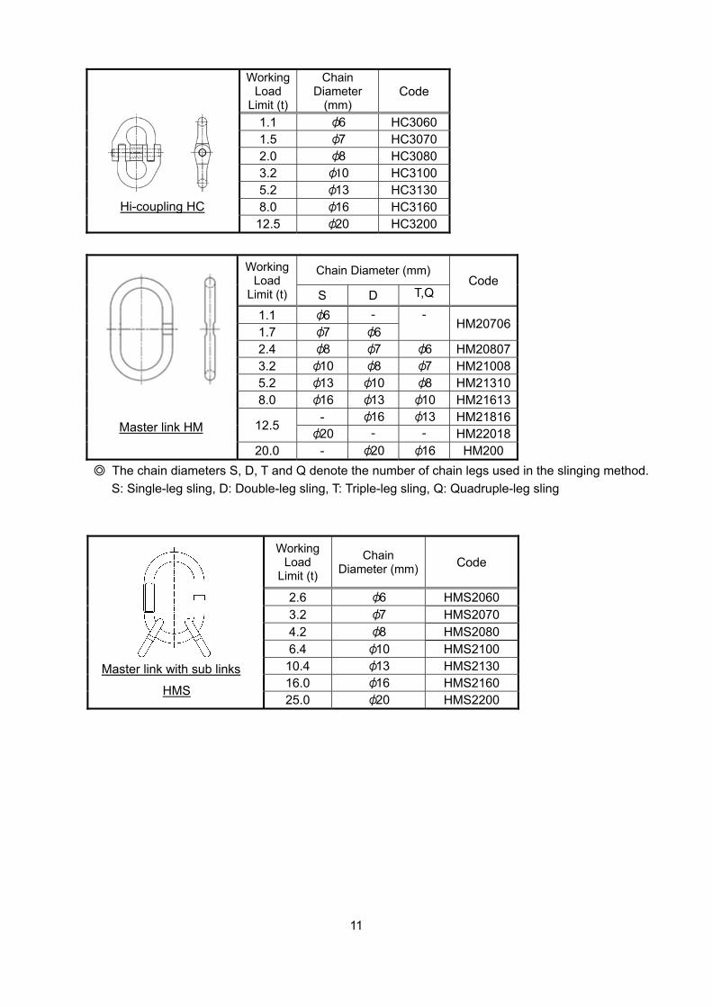
Working Load
Limit (t)
Chain Diameter
(mm) Code
1.1 φ6 HC3060 1.5 φ7 HC3070 2.0 φ8 HC3080 3.2 φ10 HC3100 5.2 φ13 HC3130 8.0 φ16 HC3160
12.5 φ20 HC3200 Hi-coupling HC
Working Load
Limit (t)
Chain Diameter (mm) Code
S D T,Q
1.1 φ6 - - HM20706
1.7 φ7 φ6 2.4 φ8 φ7 φ6 HM20807 3.2 φ10 φ8 φ7 HM21008 5.2 φ13 φ10 φ8 HM21310 8.0 φ16 φ13 φ10 HM21613
12.5 - φ16 φ13 HM21816
φ20 - - HM22018 20.0 - φ20 φ16 HM200
◎ The chain diameters S, D, T and Q denote the number of chain legs used in the slinging method.
S: Single-leg sling, D: Double-leg sling, T: Triple-leg sling, Q: Quadruple-leg sling
Master link HM
Working Load
Limit (t)
Chain Diameter (mm) Code
2.6 φ6 HMS2060 3.2 φ7 HMS2070 4.2 φ8 HMS2080 6.4 φ10 HMS2100
10.4 φ13 HMS2130 16.0 φ16 HMS2160 25.0 φ20 HMS2200
Master link with sub links
HMS
12
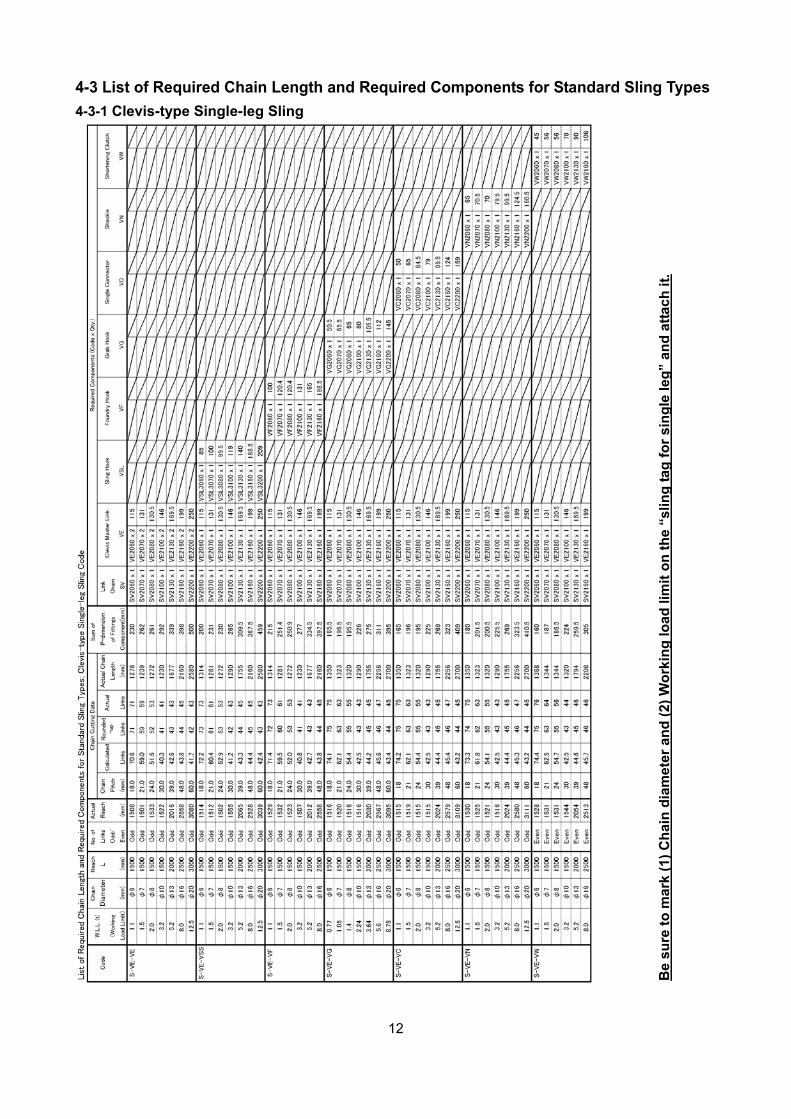
4-3 List of Required Chain Length and Required Components for Standard Sling Types
4-3-1 Clevis-type Single-leg Sling
Be
sure
to
mar
k (1
) C
hai
n d
iam
eter
an
d (
2) W
ork
ing
load
lim
it o
n t
he
“slin
g t
ag f
or
sin
gle
leg
” an
d a
ttac
h i
t.
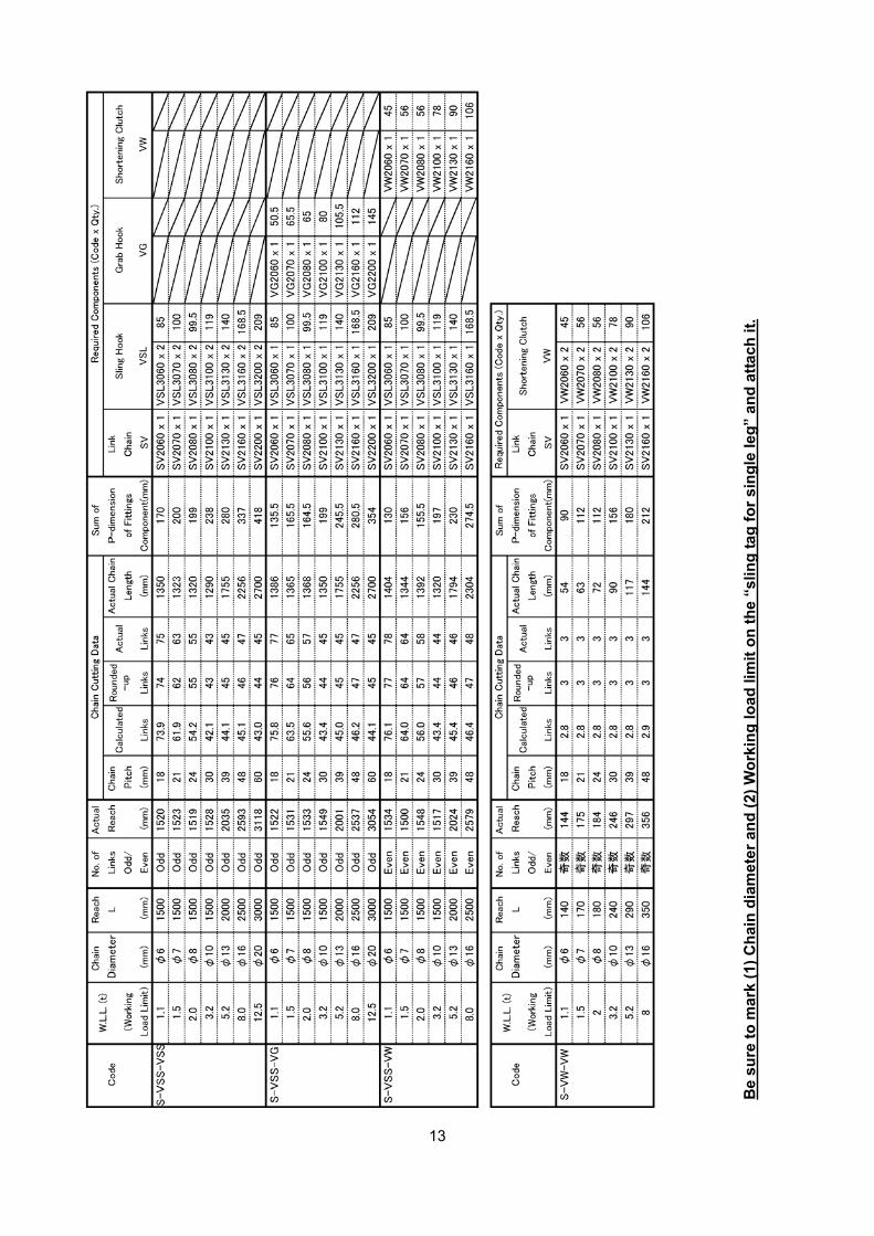
13
Be
sure
to
mar
k (1
) C
hai
n d
iam
eter
an
d (
2) W
ork
ing
load
lim
it o
n t
he
“slin
g t
ag f
or
sin
gle
leg
” an
d a
ttac
h i
t.
14
4-3-2 Clevis-type Double-leg Sling
Be
sure
to
mar
k (1
) C
hai
n d
iam
eter
, (2)
Wo
rkin
g lo
ad li
mit
an
d (
3) N
o. o
f ch
ain
leg
s o
n t
he
“slin
g t
ag f
or
do
ub
le t
o q
uad
rup
le le
gs”
an
d a
ttac
h it
.
15
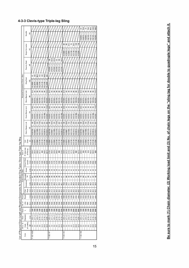
4-3-3 Clevis-type Triple-leg Sling
Be
sure
to
mar
k (1
) C
hai
n d
iam
eter
, (2)
Wo
rkin
g lo
ad li
mit
an
d (
3) N
o. o
f ch
ain
leg
s o
n t
he
“slin
g t
ag f
or
do
ub
le t
o q
uad
rup
le le
gs”
an
d a
ttac
h it
.
16
4-3-4 Clevis-type Quadruple-leg Sling
Be
sure
to
mar
k (1
) C
hai
n d
iam
eter
, (2)
Wo
rkin
g lo
ad li
mit
an
d (
3) N
o. o
f ch
ain
leg
s o
n t
he
“slin
g t
ag f
or
do
ub
le t
o q
uad
rup
le le
gs”
an
d a
ttac
h it
.
17
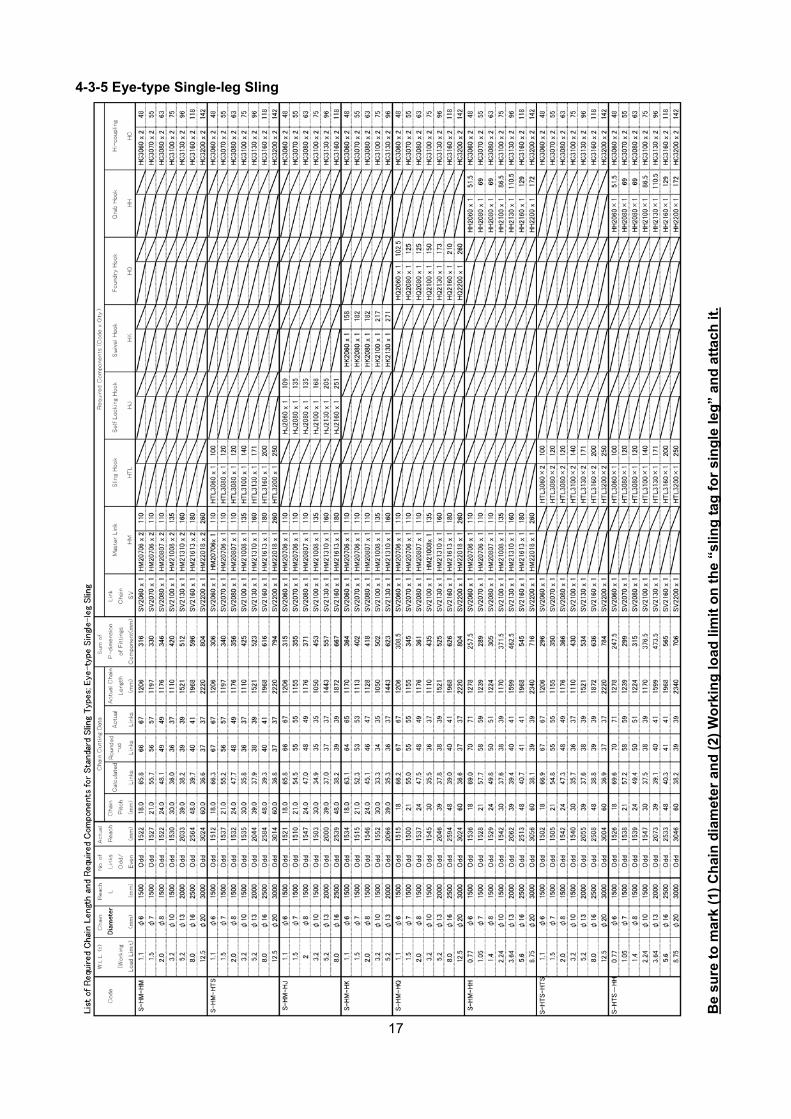
4-3-5 Eye-type Single-leg Sling
Be
sure
to
mar
k (1
) C
hai
n d
iam
eter
an
d (
2) W
ork
ing
load
lim
it o
n t
he
“slin
g t
ag f
or
sin
gle
leg
” an
d a
ttac
h i
t.
18
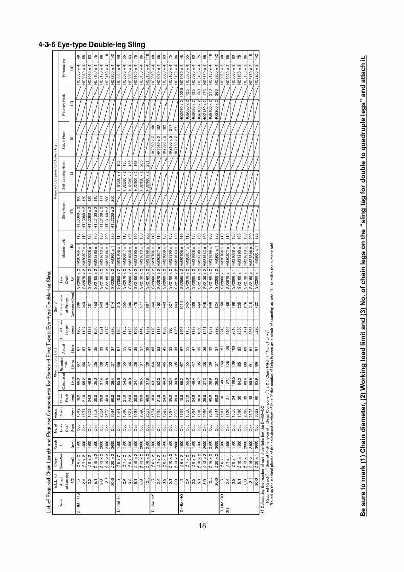
4-3-6 Eye-type Double-leg Sling
B
e su
re t
o m
ark
(1)
Ch
ain
dia
met
er, (
2) W
ork
ing
load
lim
it a
nd
(3)
No
. of
chai
n le
gs
on
th
e “s
ling
tag
fo
r d
ou
ble
to
qu
adru
ple
leg
s” a
nd
att
ach
it.
19
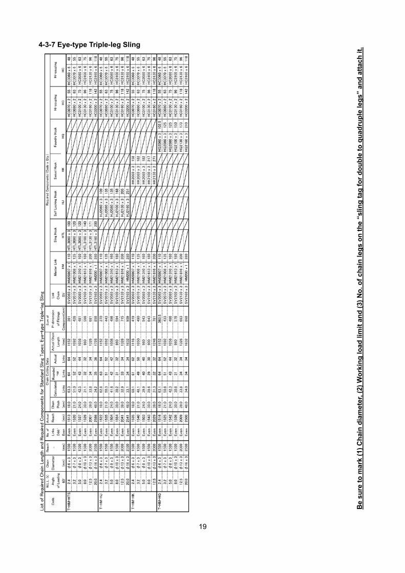
4-3-7 Eye-type Triple-leg Sling
Be
sure
to
mar
k (1
) C
hai
n d
iam
eter
, (2)
Wo
rkin
g lo
ad li
mit
an
d (
3) N
o. o
f ch
ain
leg
s o
n t
he
“slin
g t
ag f
or
do
ub
le t
o q
uad
rup
le le
gs”
an
d a
ttac
h it
.
20
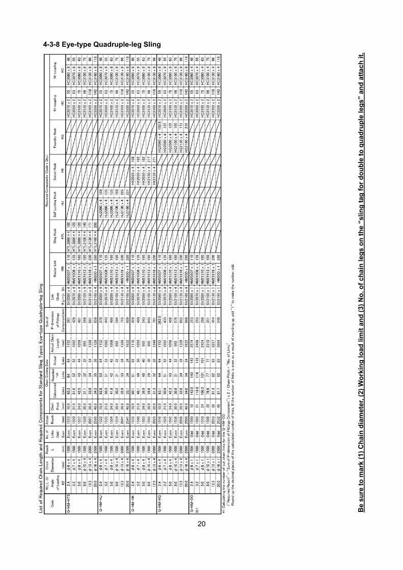
4-3-8 Eye-type Quadruple-leg Sling
Be
sure
to
mar
k (1
) C
hai
n d
iam
eter
, (2)
Wo
rkin
g lo
ad li
mit
an
d (
3) N
o. o
f ch
ain
leg
s o
n t
he
“slin
g t
ag f
or
do
ub
le t
o q
uad
rup
le le
gs”
an
d a
ttac
h it
.
21
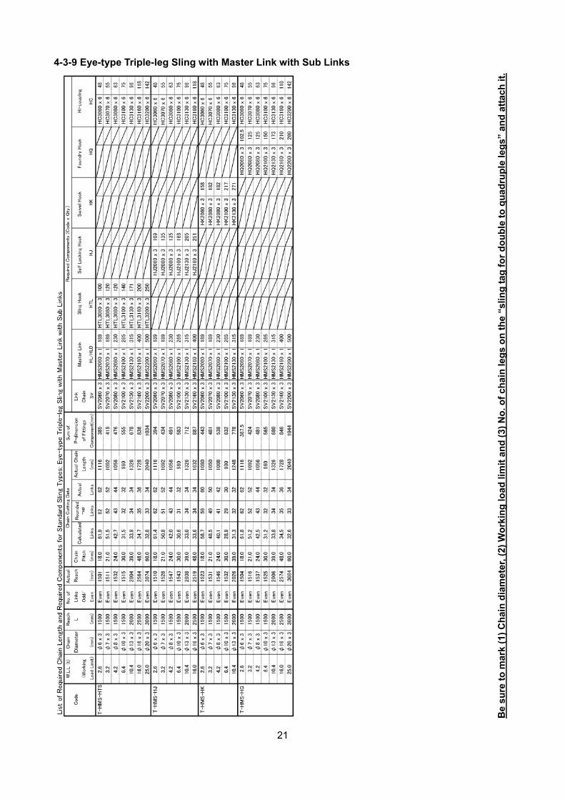
4-3-9 Eye-type Triple-leg Sling with Master Link with Sub Links
Be
sure
to
mar
k (1
) C
hai
n d
iam
eter
, (2)
Wo
rkin
g lo
ad li
mit
an
d (
3) N
o. o
f ch
ain
leg
s o
n t
he
“slin
g t
ag f
or
do
ub
le t
o q
uad
rup
le le
gs”
an
d a
ttac
h it
.
22
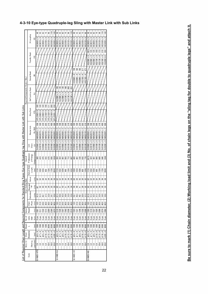
4-3-10 Eye-type Quadruple-leg Sling with Master Link with Sub Links
Be
sure
to
mar
k (1
) C
hai
n d
iam
eter
, (2)
Wo
rkin
g lo
ad li
mit
an
d (
3) N
o. o
f ch
ain
leg
s o
n t
he
“slin
g t
ag f
or
do
ub
le t
o q
uad
rup
le le
gs”
an
d a
ttac
h it
.
23
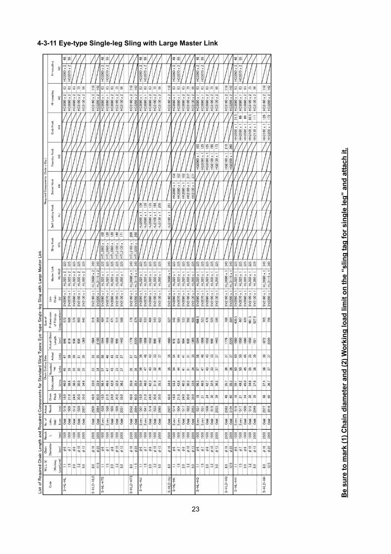
4-3-11 Eye-type Single-leg Sling with Large Master Link
Be
sure
to
mar
k (1
) C
hai
n d
iam
eter
an
d (
2) W
ork
ing
load
lim
it o
n t
he
“slin
g t
ag f
or
sin
gle
leg
” an
d a
ttac
h i
t.
24
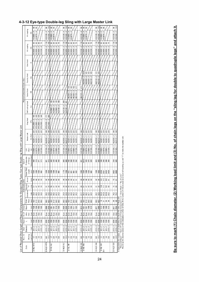
4-3-12 Eye-type Double-leg Sling with Large Master Link
Be
sure
to
mar
k (1
) C
hai
n d
iam
eter
, (2)
Wo
rkin
g lo
ad li
mit
an
d (
3) N
o. o
f ch
ain
leg
s o
n t
he
“slin
g t
ag f
or
do
ub
le t
o q
uad
rup
le le
gs”
an
d a
ttac
h it
.
25
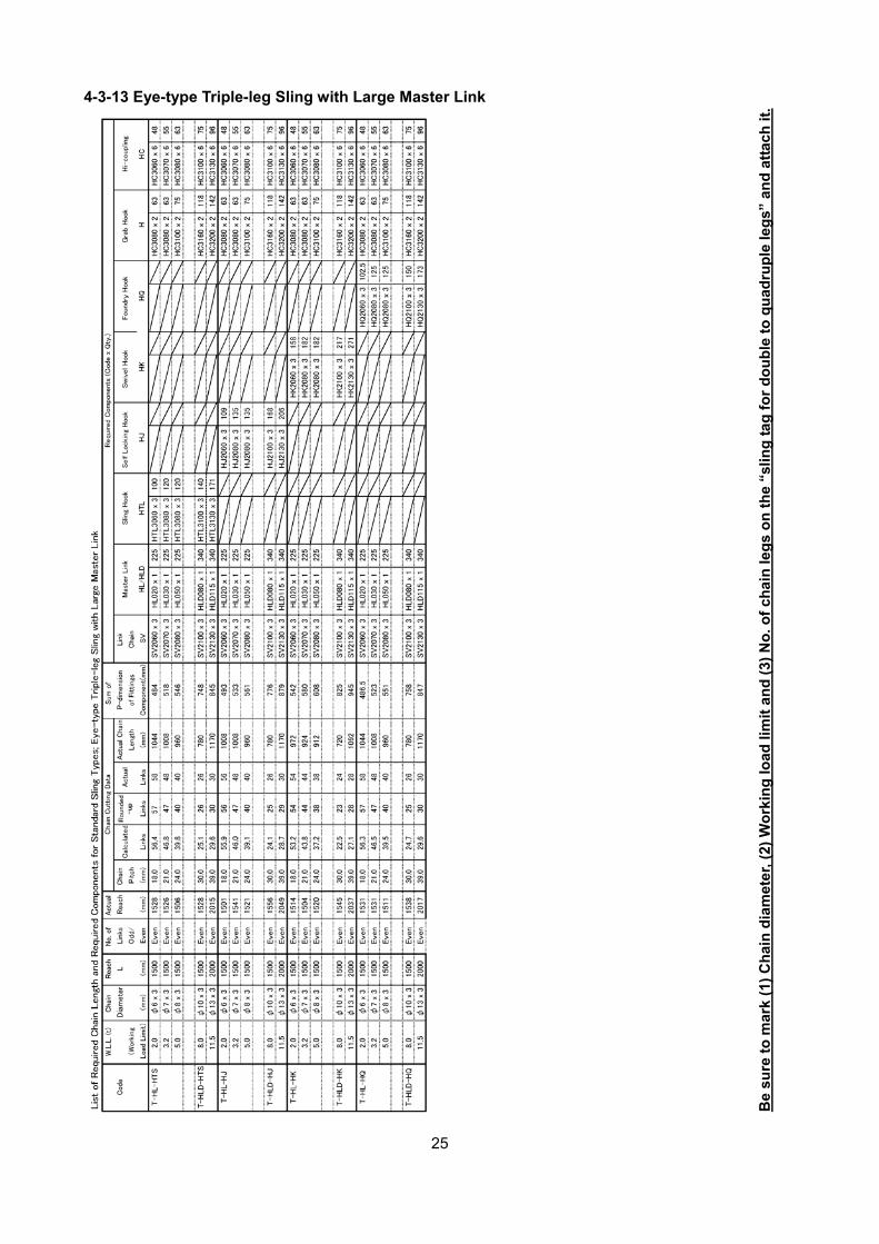
4-3-13 Eye-type Triple-leg Sling with Large Master Link
Be
sure
to
mar
k (1
) C
hai
n d
iam
eter
, (2)
Wo
rkin
g lo
ad li
mit
an
d (
3) N
o. o
f ch
ain
leg
s o
n t
he
“slin
g t
ag f
or
do
ub
le t
o q
uad
rup
le le
gs”
an
d a
ttac
h it
.
26
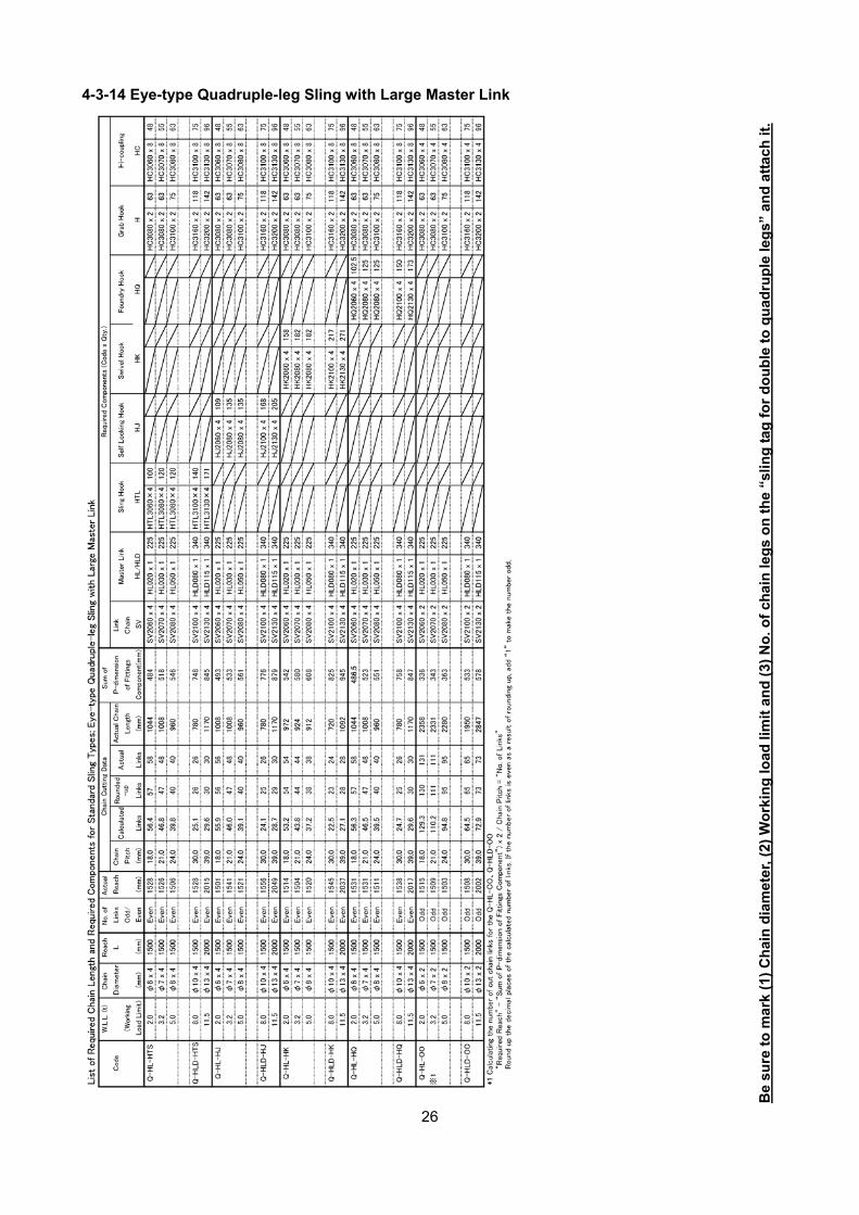
4-3-14 Eye-type Quadruple-leg Sling with Large Master Link
Be
sure
to
mar
k (1
) C
hai
n d
iam
eter
, (2)
Wo
rkin
g lo
ad li
mit
an
d (
3) N
o. o
f ch
ain
leg
s o
n t
he
“slin
g t
ag f
or
do
ub
le t
o q
uad
rup
le le
gs”
an
d a
ttac
h it
.

27
<MEMO>

28
www.kito.com
Top Related