


Languages
Pages
Legal


High School Physics DayApril 3rd, 2013
Ultrasound Physics & Instrumentation

Pegasus Lectures, Inc.COPYRIGHT 2006
“SPI in a Nutshell”Disclaimer:
This is an overview of some important concepts in ultrasound medical imaging intended for high school physics students. It is intended to spark student interest in physics and the myriad of applications of physics, including medical ultrasound. This is not a complete introduction to medical ultrasound – there are many important topics not mentioned due to time constraints. Some slides are based on Pegasus Lectures, copyrighted material.

“SPI in a Nutshell” Outline
Basic Physics Overview
Wave physics
Transducers
Piezoelectric crystals
Instrumentation Overview
From pulses to images
Attenuation and Some Example of Imaging Artifacts
Signal-to-noise ratio
Doppler and Hemodynamics
Bioeffects
Mechanical and thermal indexes

Pegasus Lectures, Inc.COPYRIGHT 2006
Metric AbbreviationsThink about how much easier the metric system is than the English system; all you have to do is move the decimal point by the number of places specified by the exponent.
G = 109 1,000,000,000M = 106 1,000,000k = 103 1,000h = 102 100da = 101 10d = 10-1 0.1c = 10-2 0.01m = 10-3 0.001 = 10-6 0.000001n = 10-9 0.000000001

Pegasus Lectures, Inc.COPYRIGHT 2006
Distance Equation
We will begin by calculating the time it takes for sound to travel 1 cm in the body (assuming a propagation velocity of 1540 m/sec). Since we want to solve for time, we must rewrite the equation in the form time = distance/rate.
So it takes 6.5 sec to travel 1 cm or:13 sec to image a structure at 1 cm because of the roundtrip effect.
26
distancetime
rate1 cm 1 10 m
so time = 6.5 10 sec 6.5 secm m
1540 1540sec sec
Distance rate time

Pegasus Lectures, Inc.COPYRIGHT 2006
Distance Equation
Time Distance Imaging Depth
6.5 sec 1 cm 0.5 cm
13 sec 2 cm 1 cm
26 sec 4 cm 2 cm
39 sec 6 cm 3 cm
52 sec 8 cm 4 cm
65 sec 10 cm 5 cm
78 sec 12 cm 6 cm
91 sec 14 cm 7 cm
104 sec 16 cm 8 cm
117 sec 18 cm 9 cm
130 sec 20 cm 10 cm
0 cm
1 cm
6.5 sec
6.5
sec

Pegasus Lectures, Inc.COPYRIGHT 2006
Time of Flight in the Body
Fig. 3: Imaging 1 cm Requires 13 sec (Pg 39)

Pegasus Lectures, Inc.COPYRIGHT 2006
Addition of Waves
-2
-1.5
-1
-0.5
0
0.5
1
1.5
2
0
0.25 0.5
0.75 1
Time (sec)
Am
plitu
de
-1
-0.75
-0.5
-0.25
0
0.25
0.5
0.75
1
0
0.25 0.5
0.75 1
Time (sec)
Am
plitu
de Sum = 0
-2
-1.5
-1
-0.5
0
0.5
1
1.5
2
0
0.25 0.5
0.75 1
Time (sec)
Am
plitu
deConstructive Interference
Destructive Interference
Partial Constructive Interference
Pegasus Lectures, Inc.COPYRIGHT 2006
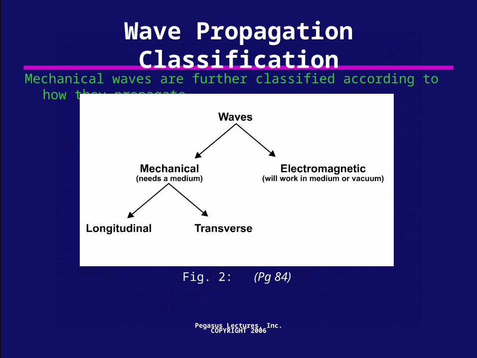
Wave Propagation ClassificationMechanical waves are further classified according to how they propagate.
Fig. 2: (Pg 84)

Pegasus Lectures, Inc.COPYRIGHT 2006
Transverse Wave Propagation
Fig. 3: Transverse Waves (Pg 85)
Transverse waves propagate by particle motion that is perpendicular or “transverse” to the wave propagation direction.
Pegasus Lectures, Inc.COPYRIGHT 2006
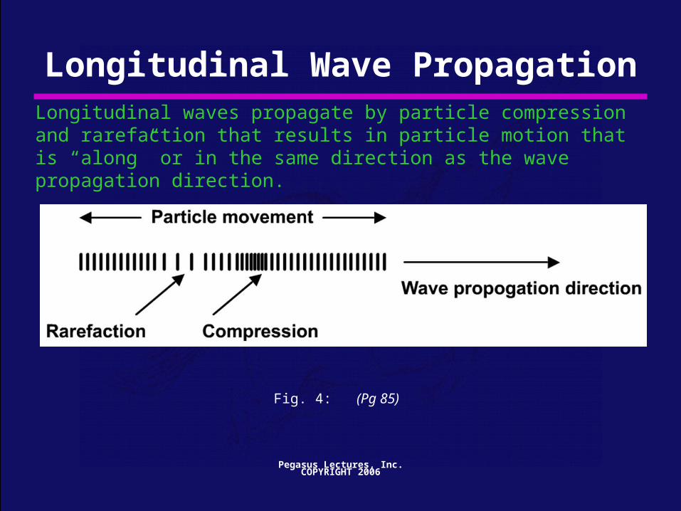
Longitudinal Wave Propagation
Fig. 4: (Pg 85)
Longitudinal waves propagate by particle compression and rarefaction that results in particle motion that is “along” or in the same direction as the wave propagation direction.

Pegasus Lectures, Inc.COPYRIGHT 2006
Wave CharacteristicsAs sound propagates, it causes mechanical changes in the medium
Frequency :
Propagation Speed :
Wavelength :
Amplitude :
1f Hz = and Period ( T : sec )
sec
c ( m/sec )
( meters )
A ( Volts, or any units for acoustic variable
s )

Pegasus Lectures, Inc.COPYRIGHT 2006
Graphical Depiction of a 2 Hz wave
Fig. 10: (Pg 93)

Pegasus Lectures, Inc.COPYRIGHT 2006
Wavelength EquationThe wavelength of a sound wave depends on both the frequency and the propagation speed.
A higher propagation speed “stretches” out the wave.
A lower frequency “stretches” out the wave.
Pegasus Lectures, Inc.COPYRIGHT 2006
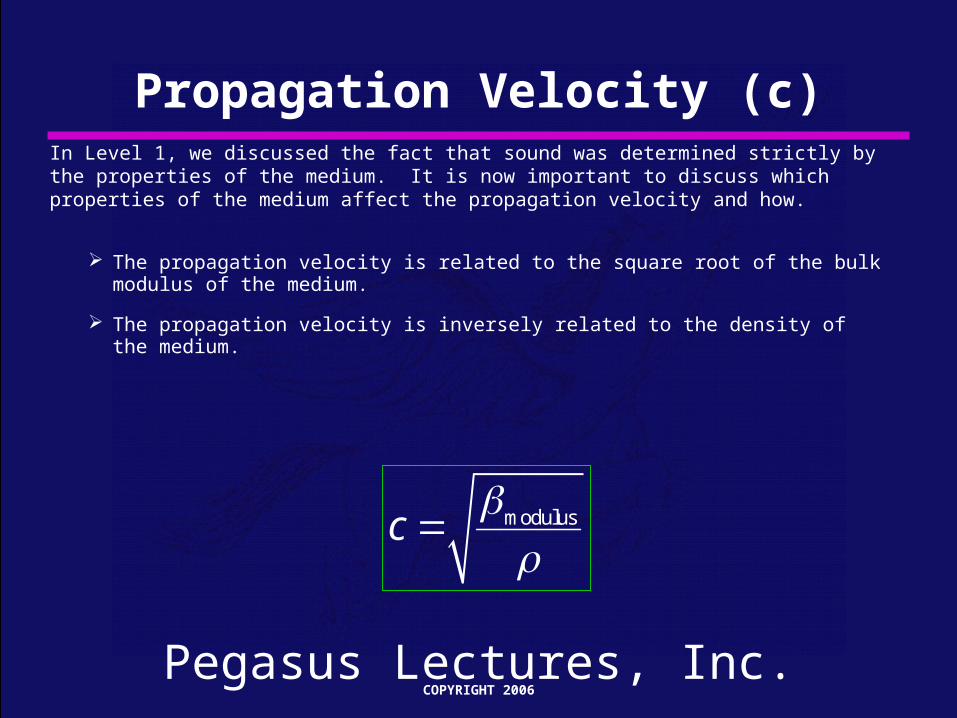
Propagation Velocity (c)In Level 1, we discussed the fact that sound was determined strictly by the properties of the medium. It is now important to discuss which properties of the medium affect the propagation velocity and how.
The propagation velocity is related to the square root of the bulk modulus of the medium.
The propagation velocity is inversely related to the density of the medium.
modulusc
Pegasus Lectures, Inc.COPYRIGHT 2006
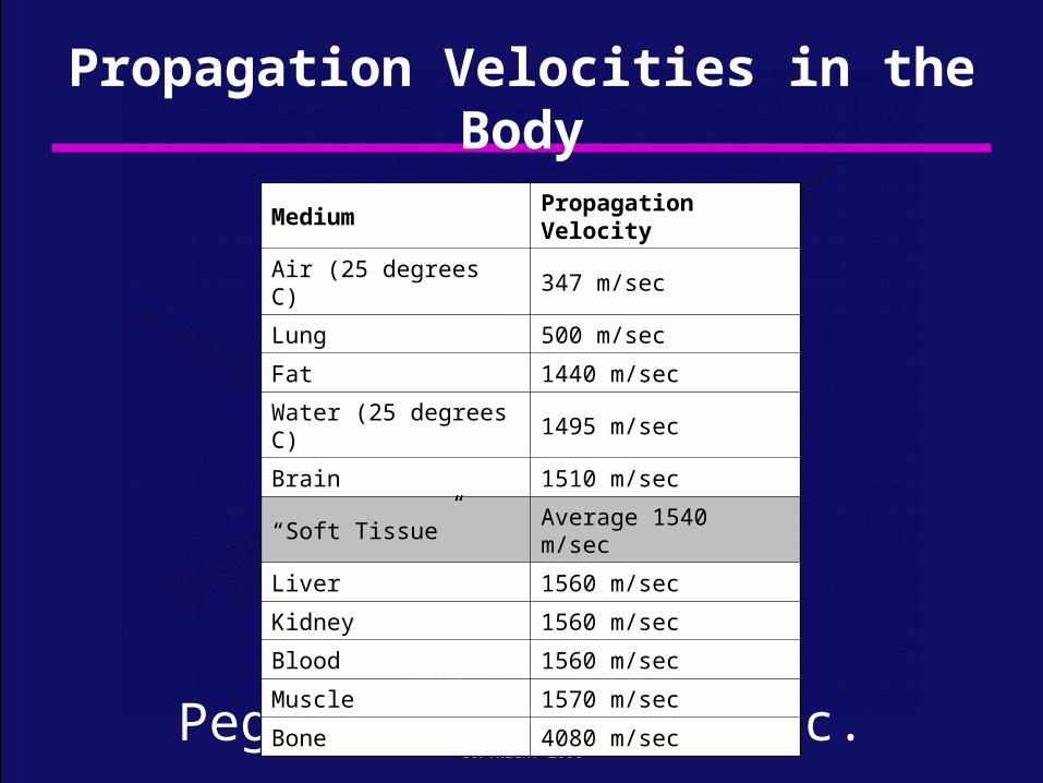
Propagation Velocities in the Body
Table 5: (Pg 121)
Medium Propagation Velocity
Air (25 degrees C) 347 m/sec
Lung 500 m/sec
Fat 1440 m/sec
Water (25 degrees C) 1495 m/sec
Brain 1510 m/sec
“Soft Tissue” Average 1540 m/sec
Liver 1560 m/sec
Kidney 1560 m/sec
Blood 1560 m/sec
Muscle 1570 m/sec
Bone 4080 m/sec

Pegasus Lectures, Inc.COPYRIGHT 2006
Fig. 17: (Pg 606)
Speed Error Artifact ExampleThis speed error case results from a needle entering into a cystic structure. The needle appears bent giving rise to the name “broken needle” or “bayonet” sign.

Pegasus Lectures, Inc.COPYRIGHT 2006
Relationship of intensity with Amplitude
2AmplitudePower
Intensityarea area
So if the amplitude is doubled, the power increases by a factor of four, resulting in an increase in intensity by a factor of four.
Recall that voltage is a measure of amplitude.

Pegasus Lectures, Inc.COPYRIGHT 2006
Same Frequency – Different Amplitude
Fig. 33: (Pg 135)

Pegasus Lectures, Inc.COPYRIGHT 2006
AttenuationAttenuation is a measure of how the medium affects the wave.
Attenuation will be divided into three subtopics:
Absorption
Reflection
Refraction

Pegasus Lectures, Inc.COPYRIGHT 2006
Reflection – Acoustic ImpedanceThe amount of reflection from a boundary is determined by the acoustic impedance mismatch.
What this equation says is: the greater the acoustic impedance mismatch between mediums, the greater the amount of reflection.
How much reflection would there be if z2 = z1?

Pegasus Lectures, Inc.COPYRIGHT 2006
TransmissionAll of the energy at an interface between media must be conserved.
Excluding absorption, this means that whatever energy does not reflect must transmit (continue on through the patient).
Can you imagine why it is so important to not have too much reflection from any one interface?
Pegasus Lectures, Inc.COPYRIGHT 2006
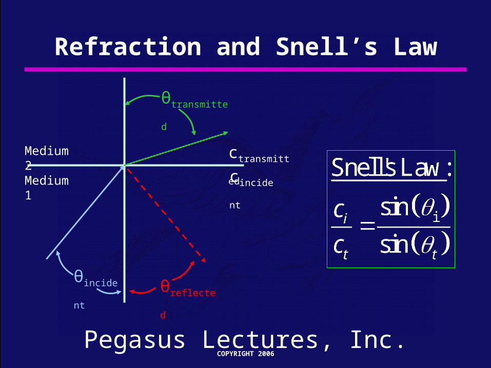
Refraction and Snell’s Law
θincident
θtransmitted
θreflected
cincident
ctransmittedMedium 2
Medium 1
Pegasus Lectures, Inc.COPYRIGHT 2006
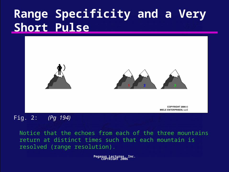
Range Specificity and a Very Short Pulse
Fig. 2: (Pg 194)
Notice that the echoes from each of the three mountains return at distinct times such that each mountain is resolved (range resolution).

Pegasus Lectures, Inc.COPYRIGHT 2006
Foundational PW Drawing Revisited
Fig. 25: (Pg 220)
Pegasus Lectures, Inc.COPYRIGHT 2006
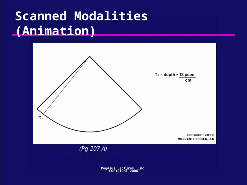
Scanned Modalities (Animation)
(Pg 207 A)

Pegasus Lectures, Inc.COPYRIGHT 2006
Creating a Frame & Acoustic LinesEach transmit burst or “pulse” represents the beginning of one acoustic line. Multiple acoustic lines constitute one frame (or an image).
Time
Transmit 1 Transmit 2 Transmit 3

Pegasus Lectures, Inc.COPYRIGHT 2006
Ultrasound transducers use the piezoelectric effect to convert electrical energy into mechanical energy and mechanical energy back into electrical energy.
Piezoelectric Effect
PZ
TP
ZT
Electrical to acoustic transformation
Acoustic to electrical transformation

Pegasus Lectures, Inc.COPYRIGHT 2006
Piezoelectric Effect
Fig. 2a Expansion Fig. 2b Contraction Fig. 2c At Rest
(Pg 235)

Pegasus Lectures, Inc.COPYRIGHT 2006
Lateral Resolution and Beamwidth
Fig. 14: (Pg 248)
Lateral Resolution Beamwidth
The lateral resolution equals the lateral beamwidth dimension. If the beam is wider than the distance between two structures, the echo from both structures will overlap, making it impossible to distinguish between the two structures laterally.

Pegasus Lectures, Inc.COPYRIGHT 2006
SNR (can ask SBI students about it)
(Pg 307)
307 A: Poor SNR 307 B: Good SNR 307 C: Poor Apparent SNR
307 D: Poor Apparent SNR 307 E: Good SNR 307 F: Poor Apparent SNR
Pegasus Lectures, Inc.COPYRIGHT 2006
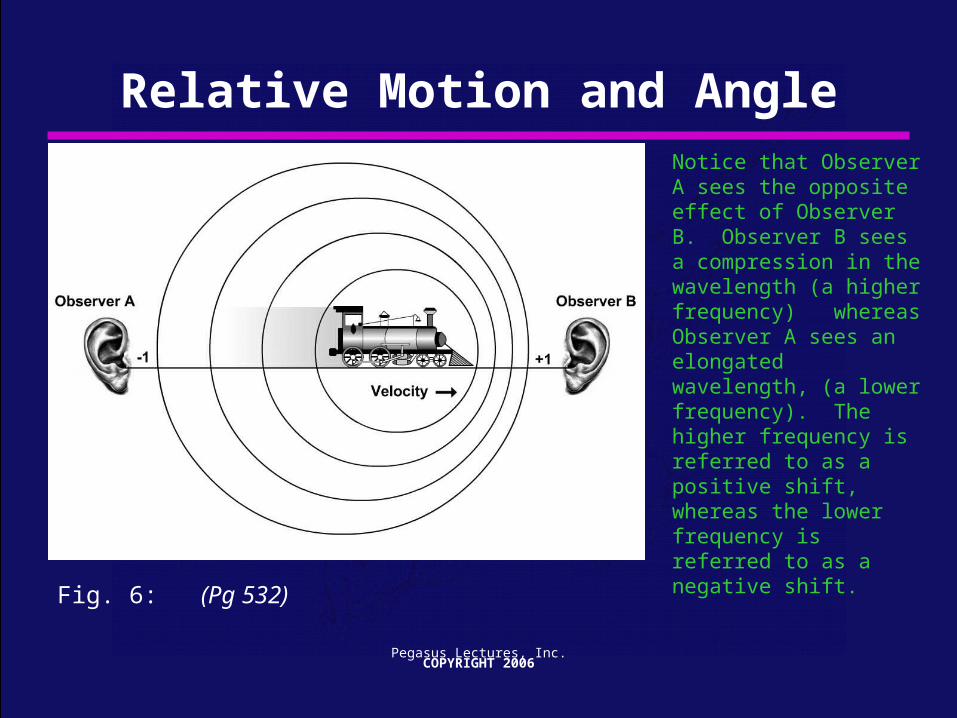
Relative Motion and AngleNotice that Observer A sees the opposite effect of Observer B. Observer B sees a compression in the wavelength (a higher frequency) whereas Observer A sees an elongated wavelength, (a lower frequency). The higher frequency is referred to as a positive shift, whereas the lower frequency is referred to as a negative shift.
Fig. 6: (Pg 532)

Pegasus Lectures, Inc.COPYRIGHT 2006
Fast Moving Plane (Animation)
(Pg 522)

Pegasus Lectures, Inc.COPYRIGHT 2006
Doppler EquationIn Level 1, we expressed the Doppler equation in a simplified form, ignoring the angular correction of the cosine term. We can now add the angular correction of the cosine term as follows:
2 cosoDop
f vf
c
Where:
( )
cos
= (
Dopf Doppler shifted frequency relative to transmit frequency
v velocity of the sound source (target)
angle correction
insonification angle or ang
)
c
le to flow
speed of sound

Pegasus Lectures, Inc.COPYRIGHT 2006
Determining Flow Direction
Fig. 54: (Pg 576)
Notice in this example that the flow is not changing in direction or speed (constant velocity) yet the flow looks very different traversing the vessel. This appearance is the result of the changing angle to flow formed between the constant flow direction and the varying steering angle.

Pegasus Lectures, Inc.COPYRIGHT 2006
Flow Direction: Case 3 (Animation)
(Pg 580 C)

Pegasus Lectures, Inc.
Assuming no loss of energy to heat, as the flow accelerates, there is a decrease in potential energy and a compensatory increase in kinetic energy (transitioning from region 1 to region 2) As the velocity decreases (region 2 to region 3) the kinetic energy decreases and the potential energy increases back to the same level as in region 1.
Flow Conversion between Potential and Kinetic Energy
Fig. 1: (Pg 742)
PE
KE PE
KE
PE
KE
Region 1Lower Velocity
Region 2Higher Velocity
Region 3Lower Velocity

Pegasus Lectures, Inc.
Bioeffects Intensity Restrictions
“Highest Risk of Thermal”
“Lowest Risk of Thermal”
“Lowest Risk of Mechanical”
“Greatest Risk of Mechanical” B-Mode
PW
PW(larger gate)
CW

Pegasus Lectures, Inc.COPYRIGHT 2006
Basic System Functions
Fig. 6: (Pg 308)
American Registry of Diagnostic Medical Sonographers (ARDMS)
• Must be registered sonographer (ARDMS or CCI) to practice in Florida
• CCI exams easier than ARDMS
• Two principal prerequisites to take ARDMS board exams:
• Passing grade in ultrasound physics course http://www.ardms.org/credentials_examinations/
• Clinical experience (several months, duration depends on specific exam) http://www.ardms.org/files/downloads/Prerequisite_Chart.pdf

Thank you!
• Questions?• If not, take your worksheet and follow SBI students to ultrasound lab• You can find this presentation at my website:
http://www.nhn.ou.edu/~blandon/click on “SBI High School Physics Day”
Top Related