


Languages
Pages
Legal


ISSN: 2394-6881
International Journal of Engineering Technology and Management (IJETM)
Available Online at www.ijetm.org
Volume 2, Issue 3, May-June 2015, Page No. 53-57
Corresponding author: Ms. Nilam P. Patil
Pag
e53
Design and Evaluation of Earthing and Lightning Arrester for Grid Connected Solar Prototype System
Ms. Nilam P. Patil1, Prof. N.S.Shinde
2*
1Research Student, Department
of Technology, Shivaji University, Kolhapur.
2Professor, Department of Technology, Shivaji University, Kolhapur.
ABSTRACT The solar PV power plants have wide applications worldwide, having potential of electricity generation of 124.8 Twh. the technology of polycrystalline solar cells, panels and balance of components of the electrical systems are being established. The code of testing and performance evaluation of such systems is still under investigations. Since it is regarding electricity generation the safety norms should be followed, for which earthing and lightning arrester of the components plays important role. The research work elaborates and establishes earthing and lightning arrester designing and testing protocol for solar PV power plants, with a case study of 65kW grid connected rooftop system for industrial loads. The methodology is set for designing and safety codes developed which can be extended for solar PV power plant applications. Testing of earthing and lightning arrester safety measures found the earth leakage currents negligible and within the limits as prescribed by existing IS 3043-1986 standards.
INTRODUCTION: Case under study and design methodology: This study identifies 65KW solar PV plant installed capacity and can be commissioned at the rooftop of Valveworks India Pvt Ltd. The Grid Connected Solar Photovoltaic Power plant has been widely accepted as a viable solution to adopt alternative energy. It is estimated that plant will generate 299 kWh per day electricity for the operations as against daily average consumption of 380 kWhrs of Unit no –I. In order to promote energy conservation, the available roof adjacent/within the campus will be provided with Solar Photovoltaic Power Panels. Solar PV modules: Max peak power =250wp Voc=36V; Vmp=29V Isc=9.25A; Imp=8.65A Inverter: 60KW, 3phase& MPPT based; Vmax=800V SCADA/Monitoring System: Integrated with Remote monitoring system web based. Circuit breaker: IS/IEC 60947 part I, II, III EN 50521 DC disconnect/Switch gear: 1000V Cables: DC side=10mm2
AC side= LT: 16mm2 & HT: 185mm2
Project Specifications Name of the Building: Valveworks India Pvt Ltd, Unit II The Project 65 KW Rooftop solar PV project for Valveworks India Pvt ltd. Geographical location :16.60N, 74.30E Type of Module Mounting Structure: Fixed tilt Structures Type of PV Modules Considered for the project:c‐Si (Poly crystalline) Structure type: fixed type roof mounted Tentative Capacity: 65KW Capacity of each PV Module: 250Wp Solar Inverter: 20KVA*3 string inverters Method for Construction of Earthing Pit:
Excavation on earth for a normal earth Pit size is 1.5M X 1.5M X 3.0 M.
Use 500 mm X 500 mm X 10 mm GI Plate or Bigger Size for more Contact of Earth and reduce Earth Resistance.
Make a mixture of Wood Coal Powder Salt & Sand all in equal part
Wood Coal Powder use as good conductor of electricity, anti corrosive, rust proves for GI Plate for long life.
The purpose of coal and salt is to keep wet the soil permanently.

Ms. Nilam P. Patil, et al. International Journal of Engineering Technology and Management (IJETM)
© 2015 IJETM. All Rights Reserved.
Pag
e54
P
age5
4
Pag
e54
P
age5
4
Pag
e54
P
age5
4
Pag
e54
P
age5
4
Pag
e54
P
age5
4
Pag
e54
P
age5
4
Pag
e54
P
age5
4
Pag
e54
P
age5
4
Pag
e54
P
age5
4
Pag
e54
P
age5
4
Pag
e54
The salt percolates and coal absorbs water keeping the soil wet.
Care should always be taken by watering the earth pits in summer so that the pit soil will be wet.
Coal is made of carbon which is good conductor minimizing the earth resistant.
Salt use as electrolyte to form conductivity between GI Plate Coal and Earth with humidity.
Sand has used to form porosity to cycle water & humidity around the mixture.
Put GI Plate (EARTH PLATE) of size 500 mm X 500 mm X 10 mm in the mid of mixture.
Use Double GI Strip size 30 mm X 10 mm to connect GI Plate to System Earthling.
It will be better to use GI Pipe of size 2.5″ diameter with a Flange on the top of GI Pipe to cover GI Strip from EARTH PLATE to Top Flange.
Cover Top of GI pipe with a T joint to avoid jamming of pipe with dust & mud and also use water time to time through this pipe to bottom of earth plate.
Maintain less than one Ohm Resistance from EARTH PIT conductor to a distance of 15 meters around the EARTH PIT with another conductor dip on the Earth at least 500 mm deep.
Check Voltage between Earth Pit conductors to Neutral of Mains Supply 220V AC 50 Hz it should be less than 2.0 Volts. Length of Pipe Electrode and Earthing Pit: The resistance to earth of a pipe or plate electrode reduces rapidly within the first few feet from ground (mostly 2 to 3 meter) but after that soil resistivity is mostly uniform. After about 4 meter depth, there is no appreciable change in resistance to earth of the electrode. Except a number of rods in parallel are to be preferred to a single long rod. Amount of Salt and Charcoal (more than 8Kg): To reduce soil resistivity, it is necessary to dissolve in the moisture particle in the Soil. Some substance like Salt/Charcoal is highly conductive in water solution but the additive substance would reduce the resistivity of the soil, only when it is dissolved in the moisture in the soil after that additional quantity does not serve the Purpose. 5% moisture in Salt reduces earth resistivity rapidly and further increase in salt content will give a very little decrease in soil resistivity. The salt content is expressed in percent by weight of the moisture content in the soil. Considering 1M3 of Soil, the moisture content at 10 percent will be about 144 kg (10 percent of 1440 kg). The salt content shall be 5% of this (i.e.) 5% of 144kg, that is, about 7.2kg.
Solar Cable: Design Calculation for Maximum allowed voltage drop: Let us consider the following PV Modules for voltage drop calculation Nominal power of PV Modules Pnom = 222W Current at maximum power: Imp =7.07 A Voltage at maximum power: Vmp = 29.84 V Short Circuit Current: Ish = 7.96 A Number of panels in series in each array Np = 16 Number of arrays Na = 33 Maximum ambient temperature = 55 ºC Therefore, The peak power delivered by PV module is given by Np*Na *Pnom P = 16* 33* 222W = 117,216 W=117.216kW The voltage at the junction box is For a given array, the panels are connected in series, so the voltage of the array is the sum of the voltage of the modules. The applicable voltage at the junction box level is V= Vmp * 16 = 29.84 V * 16 = 477.44 V The total current is the addition of the current of each single array. There are 11 arrays per junction box. I = Imp *11 = 7.07*11 = 77.77 A The voltage drop between the generating point and the point of connection to the Public Distribution Network or indoor installations shall not exceed 1.5% at nominal current. The maximum allowed voltage drop is: Vdrop = 0.01 x 477.44 V = 4.77 V The cable section is, in this case, defined as follows
𝑆 =𝐿 ∗ 𝐼
γ ∗ Vdrop
Where
L: length of the line (positive + negative) 2 x 42 = 84 m Imp: nominal current 77.77 A γ: conductivity of copper (at 70ºC) 46.82 m/Ω.mm2
Vdrop: Maximum voltage drop 4.77 V This leads to:
𝑆 =84 ∗ 77.77
46.82 ∗ 4.77
= 29.25 approximated to 35 mm2 (i.e., required size of the cable)
Ms. Nilam P. Patil, et al. International Journal of Engineering Technology and Management (IJETM)
© 2015 IJETM. All Rights Reserved.
Pag
e55
P
age5
5
Pag
e55
P
age5
5
Pag
e55
P
age5
5
Pag
e55
P
age5
5
Pag
e55
P
age5
5
Pag
e55
P
age5
5
Pag
e55
P
age5
5
Pag
e55
P
age5
5
Pag
e55
P
age5
5
Pag
e55
P
age5
5
Pag
e55
Figure 1: Single line diagram for 65kW solar power plant:
Figure 2: Single line diagram with detailed earthing connections
Rooftop Drawing: Northern lights roofs have that distinctive industrial saw tooth profile. The north facing glazing gains light without glare and overheating. The solar panels will be south facing with optimum angle as shown in the figure. The total rooftop area is 750 m2. Rooftop identification is the first step while designing the solar PV system. Available terrace/rooftop area: 750sq meter Proposed Solar PV System: 65KW Strength of the structures: Rooftop SPV Array Peak Power: 65KWp No. of SPV strings: 15 Connection of PV modules in each string: Series Inverter: 60KW MPPT based Inverter
Figure 3:
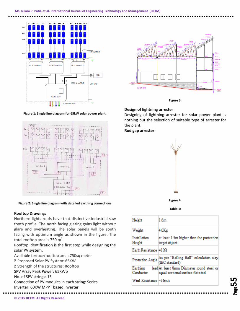
Design of lightning arrester Designing of lightning arrester for solar power plant is nothing but the selection of suitable type of arrester for the plant. Rod gap arrester:
Figure 4:
Table 1:

Ms. Nilam P. Patil, et al. International Journal of Engineering Technology and Management (IJETM)
© 2015 IJETM. All Rights Reserved.
Pag
e56
P
age5
6
Pag
e56
P
age5
6
Pag
e56
P
age5
6
Pag
e56
P
age5
6
Pag
e56
P
age5
6
Pag
e56
P
age5
6
Pag
e56
P
age5
6
Pag
e56
P
age5
6
Pag
e56
P
age5
6
Pag
e56
P
age5
6
Pag
e56
Figure 5: Construction of rod gap arrester
A lightning arrestor (in Europe: surge arrestor) is a device used on electrical power systems and telecommuni-cations systems to protect the insulation and conductors of the system from the damaging effects of lightning. The typical lightning arrestor has a high-voltage terminal and a ground terminal. When a lightning surge (or switching surge, which is very similar) travels along the power line to the arrestor, the current from the surge is diverted through the arrestor, in most cases to earth. In telegraphy and telephony, a lightning arrestor is placed where wires enter a structure, preventing damage to electronic instruments within and ensuring the safety of individuals near them. Smaller versions of lightning arrestors, also called surge protectors, are devices that are connected between each electrical conductor in power and communications systems and the Earth. These prevent the flow of the normal power or signal currents to ground, but provide a path over which high-voltage lightning current flows, bypassing the connected equipment. Their purpose is to limit the rise in voltage when a communications or power line is struck by lightning or is near to a lightning strike. Lightning Arrestors are designed to provide protection to structures against physical damage from lightning strikes. They are critically placed on a structure and connected to a lightning conductor and earthing system to safely receive a strike, safely conduct the lightning current to the earthing system and safely dissipate it in the earth. Franklin Rods:
These are metal rods installed over a structure at preferred points for a lightning strike. These terminals are connected to a network of horizontal and vertical conductors that are terminated to earthing terminals. The network of rods, conductors and earth terminals covers the protected structure in a Faraday Cage. Various sizes and shapes of Franklin Rods are available to suit an application and we have capability to design and manufacture a custom system to fit your needs.
Figure 6: Franklin rods
Franklin Rod: This air termination system is made up of a 2-8m high tapered metal, a down earth conductor and an earthing system. At a protection of level of 4 and height of 60m, the radius of coverage is limited to about 30m as shown in figure. It is normally only used to protect small structures or zones such as pylons, chimneys, tanks, water towers, aerial masts, etc.
IS No. Title
IS 732 : 1989 Code of practice for electrical wiring installation (third revision)
IS 3043 : 1987 Code of practice for earthing (first revision)
CONCLUSION As more renewable energy sources come online; they will take on greater and greater importance in the overall generation mix. There is an necessity of protection to any general system for safety purpose or to save human body or equipments in good condition. In this project, overall risk factor is also measured which shows the actual necessity of protection for the solar panels. The detail study about earthing system, lightning arrester, its types, factors affecting to the design of earthing and lightning arrester system for grid connected solar prototype of 65 kW are carried out. To meet the best design of earthing and lightning arrester for solar PV panels, standards are preferred. Practical assessment and testing of various components of items are carried out.

Ms. Nilam P. Patil, et al. International Journal of Engineering Technology and Management (IJETM)
© 2015 IJETM. All Rights Reserved.
Pag
e57
P
age5
7
Pag
e57
P
age5
7
Pag
e57
P
age5
7
Pag
e57
P
age5
7
Pag
e57
P
age5
7
Pag
e57
P
age5
7
Pag
e57
P
age5
7
Pag
e57
P
age5
7
Pag
e57
P
age5
7
Pag
e57
P
age5
7
Pag
e57
REFERENCES
1. M. Modrusan, “Tests on high-voltage metal oxide surge arresters with impulse currents”, 11, 1983
2. Getting down to earth, a practical guide to earth resistance testing
3. Jonathan Woodworth, “Guide for Selecting an Arrester Field Test Method”, Consulting Engineer Arrester Works February 18, 2008
4. Larry Pryor, “The Application and Selection of Lightning Arresters”
5. John C. Wiles ,“Photovoltaic System Grounding”, Southwest Technology Development Institute College of Engineering New Mexico State University October 2012
6. Surge protector device installation manual 7. T. C. Oehen, “Lightning Arresters and Schemes for
Testing”, A Thesis, June 1908 8. C. Drilling, M. Droldner, E.G. Jordan, “Lightning
Arresters with Spark Gaps. Requirements and Future Trends of Development and Application”
9. ATPS (2013): Design and Analysis of a 1MW Grid-Connected Solar PV System in Ghana. ATPS Working Paper No. 78 Abeeku Brew-Hammond Ebenezer Nyarko Kumi
10. N. Heraklion, “Measurement of the resistive leakage current in surge arresters under artificial rain test” ,January 2009
11. Linck, H, “Lightning Arrester Field Test Equipment and Results”, Power Apparatus and Systems, Part III. Transactions of the American Institute of Electrical Engineers (Volume:78 , Issue: 3 ) 2008
12. Zacharias G. Datsios and Pantelis N. Mikropoulos , “Safe grounding system design for a photovoltaic power station”, 8th Mediterranean Conference on Power Generation, Transmission, Distribution and Energy Conversion MEDPOWER 2012
13. F. D. Martzloff, “Lightning Protection Of Roof-Mounted Solar Cells General Electric Company”. Schenectady, New YorkWorking paper developed for a NASA-sponsored study of solar cells
14. Mohd Hisanuddin Bin Zamharir, “Study On Lightning Protection For Pv System”, 2012
Top Related