


Languages
Pages
Legal


Control Variables and Strategies for the
optimization of a WHR ORC system
A. Baccioli, M. Antonelli
Department of Energy, System, Construction and Territory Engineering (D.E.S.T.eC.)
University of Pisa, Pisa, Italy
Introduction: Small scale Waste Heat Recovery
Optimization of the system:
Waste heat recovery system often characterized by fluctuations of mass flow rate and temperature;
Working Fluid System
architecture
Expander and Heat Exchangers
Control and Management

Introduction: Small scale Waste Heat Recovery
Optimization of the system:
Waste heat recovery system often characterized by fluctuations of mass flow rate and temperature;
Working Fluid System
architecture
Expander and Heat Exchangers
Optimization
Control and Management
Introduction: Small scale Waste Heat Recovery
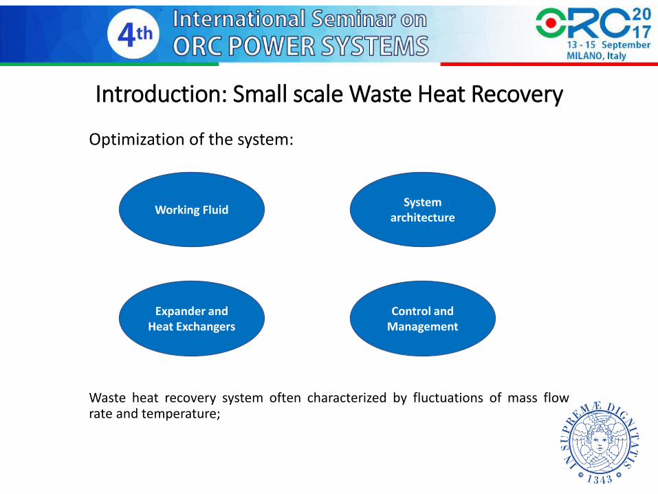
In the literature:
Definition of control strategy (steady-state analysis);
Definition of control strategy (transient-analysis)
General requirement:
Easy measurable control variables;
Control and Management
Flexibility
Efficiency
Cost reduction
Aim of the work
Aim of the study:
Create a transient model of a small scale WHR-ORC;
Compare various control strategies;
Define an optimal control strategy;
Define easy measurable control variables;
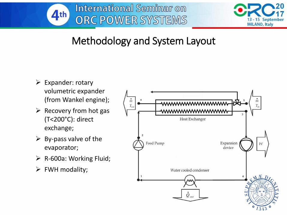
Methodology and System Layout
Expander: rotary
volumetric expander (from Wankel engine);
Recovery from hot gas (T<200°C): direct exchange;
By-pass valve of the evaporator;
R-600a: Working Fluid;
FWH modality;

Methodology: Expander
Main driving parameters:
• Displacement: 316cc
• Dead space grade μ = V1/(V3-V1) = 8%
• Introduction grade σ = (V2-V1)/ (V3-V1) = 20%
• Expansion grade ε = V3/V2; = 3.86
• Recompression grade γ = (V5-V6)/(V3-V1) = 10%

Methodology: Numerical Model
Numerical model realized in AMESim
Expander maps from a numerical model validated with experimental data
Evaporator: discretized in various nodes (finite volume). Heat exchange coefficient determined directly evaluated by the code (built-in correlations). Condenser: simplified model (two-phase chamber with imposed temperature)
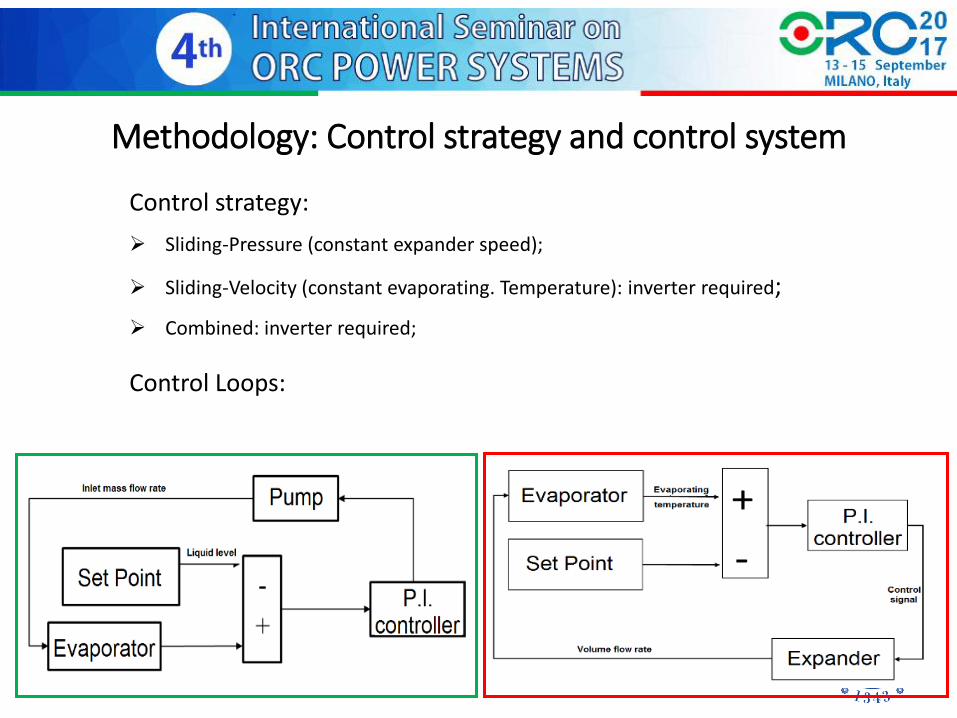
Methodology: Control strategy and control system
Control strategy:
Sliding-Pressure (constant expander speed);
Sliding-Velocity (constant evaporating. Temperature): inverter required;
Combined: inverter required;
Control Loops:

Methodology: Control strategy and control system
Control strategy:
Sliding-Pressure (constant expander speed);
Sliding-Velocity (constant evaporating. Temperature): inverter required;
Combined: inverter required;
Control Loops:
Set Point f(x,y)

Methodology: Boundary Conditions
Load diagram defined by variations both of temperature and mass flow rate
Simplification: constant condensing temperature (35°C).
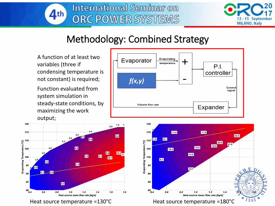
Methodology: Combined Strategy
f(x,y)
A function of at least two variables (three if condensing temperature is not constant) is required;
Function evaluated from system simulation in steady-state conditions, by maximizing the work output;
Heat source temperature =130°C Heat source temperature =180°C

Methodology: Combined Strategy
General issue: the heat source mass flow rate can be hardly measurable;
A different quantity might be more suitable to drive the evaporating temperature;
The product 𝑉 ∙ ∆𝑃𝐸𝑋𝑃 related to the expander work output and univocally defined;
For constant condensing temperature, the function became 𝑉 ∙ 𝑃𝐴𝑑𝑚: due to pressure drop 𝑃𝐴𝑑𝑚 ≠ 𝑃 𝑆𝑎𝑡
Explicit solution of the control loop

Results: Sliding Pressure/Sliding Velocity
Sliding Pressure: variation of evaporating temperature
Sliding Velocity: evaporating temperature and exp. speed
Sliding Pressure
[2500 rpm]
Sliding Velocity
[Tev=100°C]
Average Net Output [kW] 9.77 9.81
Average ORC Efficiency [%] 10.51 11.73
Average Recovery Efficiency
[%] 60.46 54.41
Average Overall Efficiency
[%] 6.35 6.38
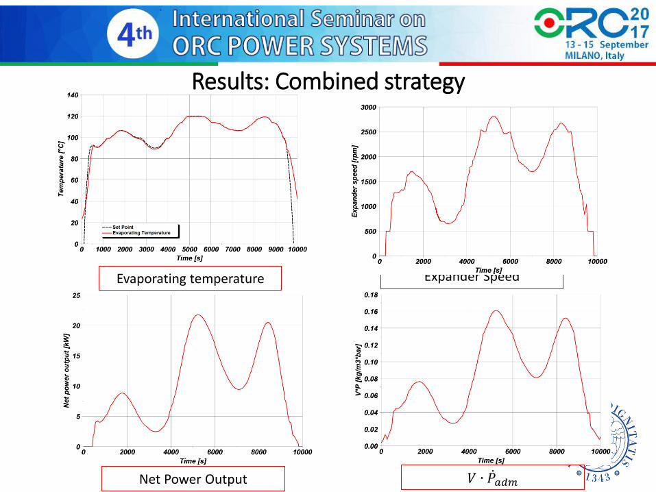
Results: Combined strategy
𝑉 ∙ 𝑃𝑎𝑑𝑚
Evaporating temperature Expander Speed
Net Power Output

Results: Comparison of the strategies
Combined strategy did not required to determine a-priori an optimal value of sliding pressure and sliding velocity;
The value of the work output however is not so much higher than that of the two other strategies: dynamic effects.
Sliding Pressure [2500 rpm]
Sliding Velocity [Tev=100°C] Combined
Average Net Output [kW] 9.77 9.81 9.93
Average ORC Efficiency [%] 10.51 11.73 9.92
Average Recovery Efficiency [%] 60.46 54.41 65.11
Average Overall Efficiency [%] 6.35 6.38 6.46

Results: Step Response
Temperature of the heat source increased from 150°C to 180°C at t=40s
Due to system inertia the evaporating temperature did not manage perfectly following the set point;
The optimal value of the set point in transient conditions differs from steady-state
A dynamic optimization of the system is required to achieve better results.
Conclusion
Control strategies for WHR ORC have been pointed out;
An optimization has been carried out;
A new control variable 𝑉 ∙ ∆𝑃𝐸𝑋𝑃 has been tested to drive the evaporating temperature of the ORC;
For each temperature and mass flow rate of the heat source the variable is univocally defined and easily measurable;
The control loop was explicitly solved.
The set point driving function was defined in steady-state conditions;
Further developments
Experimental tests are needed to verify the actual feasibilty of this choice.
Possible problems:
The small entity of the pressure drop;
Noise in the pressure values;

Thank you!
Top Related