Control Variables and Strategies for the optimization of a ... · Control Variables and Strategies...
19
Control Variables and Strategies for the optimization of a WHR ORC system A. Baccioli, M. Antonelli Department of Energy, System, Construction and Territory Engineering (D.E.S.T.eC.) University of Pisa, Pisa, Italy
Transcript of Control Variables and Strategies for the optimization of a ... · Control Variables and Strategies...

Control Variables and Strategies for the
optimization of a WHR ORC system
A. Baccioli, M. Antonelli
Department of Energy, System, Construction and Territory Engineering (D.E.S.T.eC.)
University of Pisa, Pisa, Italy
Introduction: Small scale Waste Heat Recovery
Optimization of the system:
Waste heat recovery system often characterized by fluctuations of mass flow rate and temperature;
Working Fluid System
architecture
Expander and Heat Exchangers
Control and Management

Introduction: Small scale Waste Heat Recovery
Optimization of the system:
Waste heat recovery system often characterized by fluctuations of mass flow rate and temperature;
Working Fluid System
architecture
Expander and Heat Exchangers
Optimization
Control and Management
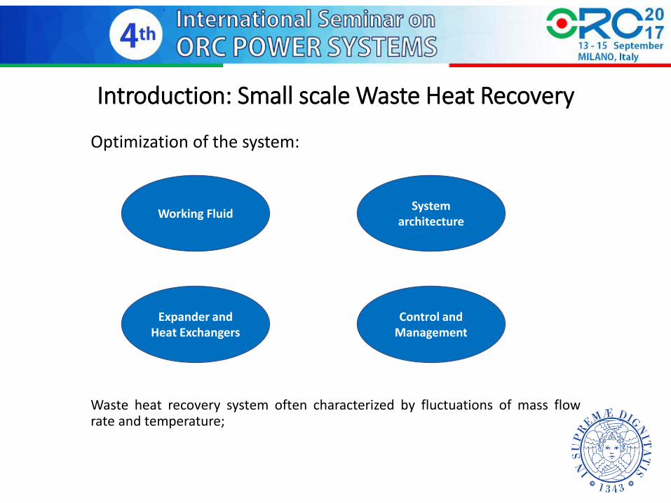
Introduction: Small scale Waste Heat Recovery
In the literature:
Definition of control strategy (steady-state analysis);
Definition of control strategy (transient-analysis)
General requirement:
Easy measurable control variables;
Control and Management
Flexibility
Efficiency
Cost reduction
Aim of the work
Aim of the study:
Create a transient model of a small scale WHR-ORC;
Compare various control strategies;
Define an optimal control strategy;
Define easy measurable control variables;
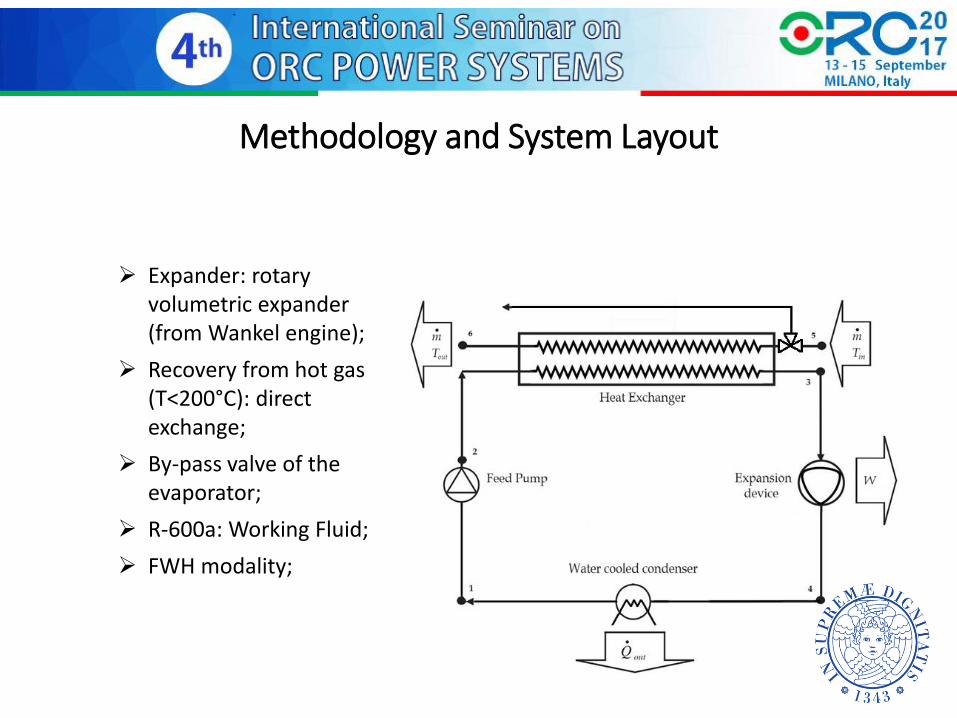
Methodology and System Layout
Expander: rotary
volumetric expander (from Wankel engine);
Recovery from hot gas (T<200°C): direct exchange;
By-pass valve of the evaporator;
R-600a: Working Fluid;
FWH modality;

Methodology: Expander
Main driving parameters:
• Displacement: 316cc
• Dead space grade μ = V1/(V3-V1) = 8%
• Introduction grade σ = (V2-V1)/ (V3-V1) = 20%
• Expansion grade ε = V3/V2; = 3.86
• Recompression grade γ = (V5-V6)/(V3-V1) = 10%

Methodology: Numerical Model
Numerical model realized in AMESim
Expander maps from a numerical model validated with experimental data
Evaporator: discretized in various nodes (finite volume). Heat exchange coefficient determined directly evaluated by the code (built-in correlations). Condenser: simplified model (two-phase chamber with imposed temperature)
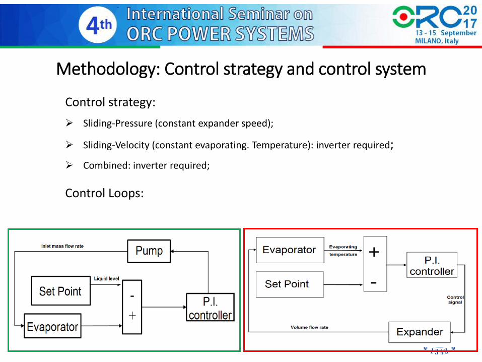
Methodology: Control strategy and control system
Control strategy:
Sliding-Pressure (constant expander speed);
Sliding-Velocity (constant evaporating. Temperature): inverter required;
Combined: inverter required;
Control Loops:

Methodology: Control strategy and control system
Control strategy:
Sliding-Pressure (constant expander speed);
Sliding-Velocity (constant evaporating. Temperature): inverter required;
Combined: inverter required;
Control Loops:
Set Point f(x,y)

Methodology: Boundary Conditions
Load diagram defined by variations both of temperature and mass flow rate
Simplification: constant condensing temperature (35°C).
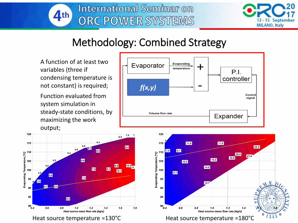
Methodology: Combined Strategy
f(x,y)
A function of at least two variables (three if condensing temperature is not constant) is required;
Function evaluated from system simulation in steady-state conditions, by maximizing the work output;
Heat source temperature =130°C Heat source temperature =180°C

Methodology: Combined Strategy
General issue: the heat source mass flow rate can be hardly measurable;
A different quantity might be more suitable to drive the evaporating temperature;
The product 𝑉 ∙ ∆𝑃𝐸𝑋𝑃 related to the expander work output and univocally defined;
For constant condensing temperature, the function became 𝑉 ∙ 𝑃𝐴𝑑𝑚: due to pressure drop 𝑃𝐴𝑑𝑚 ≠ 𝑃 𝑆𝑎𝑡
Explicit solution of the control loop

Results: Sliding Pressure/Sliding Velocity
Sliding Pressure: variation of evaporating temperature
Sliding Velocity: evaporating temperature and exp. speed
Sliding Pressure
[2500 rpm]
Sliding Velocity
[Tev=100°C]
Average Net Output [kW] 9.77 9.81
Average ORC Efficiency [%] 10.51 11.73
Average Recovery Efficiency
[%] 60.46 54.41
Average Overall Efficiency
[%] 6.35 6.38
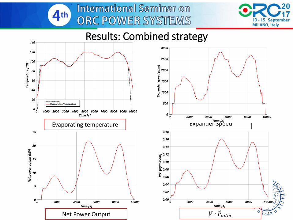
Results: Combined strategy
𝑉 ∙ 𝑃𝑎𝑑𝑚
Evaporating temperature Expander Speed
Net Power Output

Results: Comparison of the strategies
Combined strategy did not required to determine a-priori an optimal value of sliding pressure and sliding velocity;
The value of the work output however is not so much higher than that of the two other strategies: dynamic effects.
Sliding Pressure [2500 rpm]
Sliding Velocity [Tev=100°C] Combined
Average Net Output [kW] 9.77 9.81 9.93
Average ORC Efficiency [%] 10.51 11.73 9.92
Average Recovery Efficiency [%] 60.46 54.41 65.11
Average Overall Efficiency [%] 6.35 6.38 6.46

Results: Step Response
Temperature of the heat source increased from 150°C to 180°C at t=40s
Due to system inertia the evaporating temperature did not manage perfectly following the set point;
The optimal value of the set point in transient conditions differs from steady-state
A dynamic optimization of the system is required to achieve better results.
Conclusion
Control strategies for WHR ORC have been pointed out;
An optimization has been carried out;
A new control variable 𝑉 ∙ ∆𝑃𝐸𝑋𝑃 has been tested to drive the evaporating temperature of the ORC;
For each temperature and mass flow rate of the heat source the variable is univocally defined and easily measurable;
The control loop was explicitly solved.
The set point driving function was defined in steady-state conditions;
Further developments
Experimental tests are needed to verify the actual feasibilty of this choice.
Possible problems:
The small entity of the pressure drop;
Noise in the pressure values;

Thank you!