


Languages
Pages
Legal


41
CHAPTER 4: RING SHEAR TESTING PROGRAM
The laboratory tests described in this chapter were conducted to measure the drained
residual strength and the fast residual strength along slickensided discontinuities in the
Rancho Solano Clay and the San Francisco Bay Mud. The drained residual strengths and fast
residual strengths were measured by performing a series of strain-controlled ring shear tests
at varying rates of shear. The drained ring shear tests are an essential part of the laboratory
test program, because they provide an accurate baseline value for the drained residual
strength that can be used to evaluate the accuracy of the direct shear and centrifuge test
results. The fast ring shear tests are useful because they provide an improved understanding
of the fast residual shear behavior along slickensided discontinuities.
Ring shear tests are the recommended method for developing the baseline values for
drained residual strength, because of the ability of the ring shear device to apply large shear
displacements without any reversal in the direction of shear. This allows for more complete
particle orientation along the shearing plane, and a more accurate measurement of the drained
residual strength than would be achieved in traditional direct shear or triaxial tests (Bishop et
al., 1971).
The ring shear tests described in this chapter were performed at Virginia Tech using
Bromhead ring shear devices (Bromhead, 1979) built by Wykeham Farrance Engineering
Ltd. Figure 4-1 is a picture of the type of Bromhead ring shear apparatus that was used.
Residual strengths measured in the Bromhead ring shear device agree well with residual
strengths from back-analysis of failed slopes, which indicates that the Bromhead ring shear
apparatus provides an accurate measurement of the drained residual shear strength
(Bromhead and Dixon, 1986; Stark and Eid, 1992).
The Drained Residual Shear Strength of Rancho Solano Clay #1
In order to develop a baseline value for the drained residual shear strength of Rancho
Solano Clay #1, a series of drained ring shear tests were conducted using the ring shear test
procedure that is described in ASTM D 6467-99. ASTM D 6467-99 provides standardized
guidance for drained ring shear testing of cohesive soils, and tests conducted using this

42
approach should give results that are consistent with what would be measured by engineers in
practice using the Bromhead ring shear device.
Figure 4-1. Bromhead ring shear apparatus.
Test specimens were prepared and tested according to the method described in ASTM
D 6467-99. Using this approach, remolded specimens were first mixed at a water content
near the liquid limit, and then pushed through the #40 sieve (which has an opening of 0.0165
inches) to remove larger particles that could get caught between the top platen and the side
walls of the specimen container. The clay that passed the #40 sieve was then placed in the
Bromhead ring shear specimen container, and consolidated using a series of load steps to the
highest desired normal stress that would be on the shear strength envelope for that specimen.
During consolidation, the normal force was applied by a dead-weight lever-arm system, and
vertical displacements were recorded in order to ensure that pore pressures for a given load
step were completely dissipated before the next load was applied.
Once consolidation was complete, the test specimen was unloaded to the lowest
desired normal stress that would be on the shear strength envelope for that specimen, and
allowed to come to pore pressure equilibrium. Once equilibrium was achieved, the specimen
was presheared for one complete revolution (a shear displacement of 10.5 inches) at a rate of
0.58 in/min in order to create a slickensided failure plane. This allowed for a more rapid
measurement of the drained residual shear strength, because a slickensided failure surface
was already present in the specimen before slow shearing was begun.

43
Once the pore pressures that were induced by preshearing had dissipated, slow
shearing was begun. In order to minimize shear-induced pore water pressures, slow-shear
displacement rates were selected using the following equation (from ASTM D 6467-99):
50
Displacement at Failure 0.2"Displacement Rate = =Time to Failure 50 × t
(4-1)
In the above equation, t50 is the time required for the specimen to achieve 50%
consolidation under the specified normal stress. Table 4-1 lists the calculated displacement
rates for the ASTM standard ring shear tests on Rancho Solano Clay #1. Based on the data
given in Table 4-1, slow shearing of all specimens was performed at a displacement rate of
0.00071 in/min. This is a conservative lower bound displacement rate that allowed for
adequate pore pressure dissipation during shear. This displacement rate is also the lowest
displacement rate that can be applied by the Wykeham Farrance Bromhead ring shear
devices in the Virginia Tech laboratory.
Table 4-1: Calculated Displacement Rates for ASTM Standard Ring Shear Tests on Rancho Solano Clay #1
ASTM Standard Ring Shear Test Number(s) Displacement Rate Calculated Using
Casagrande t50 (in/min)
Displacement Rate Calculated Using
Taylor t50
(in/min)
R1-052003-1, R1-052003-2, and R1-052003-3 0.0024 0.0024
R1-060303-1, R1-060303-2, and R1-060303-3 0.0027 0.0049
R1-061003-1, R1-061003-2, and R1-061003-3 0.0020 0.0033
R1-061903-1, R1-061903-2, and R1-061903-3 0.0012 0.0016
Slow shearing was continued at a displacement rate of 0.00071 in/min, until the
stress-displacement curve had reached a constant minimum shear stress. Shearing was then
stopped, because a constant measurement of minimum shear stress indicates that the residual
strength state has been achieved.
After completion of the first shearing stage, the normal stress on the specimen was
increased. Pore pressures induced by this increase in normal stress were allowed to dissipate,
and the second shearing stage was begun. Once the residual strength state was achieved, the
normal stress was increased again, for a third shearing stage. Upon completion of the third

44
shearing stage, the three measured values of residual strength were used to construct a failure
envelope. This “multistage” approach to testing reduced testing time considerably, because it
was only necessary to prepare and consolidate one specimen in order to generate a three-
point failure envelope.
A total of four ASTM standard ring shear tests were performed on Rancho Solano
Clay #1. A multistage test approach was used, and each specimen was tested at normal
stresses of 7.5 psi, 14.6 psi, and 28.8 psi. This resulted in a total of twelve different
measurements of residual shear stress for this soil. Complete data sheets for each ring shear
test are given in Appendix A. Statistical analysis results of the measured residual shear
stresses are given in Table 4-2. A plot of average residual shear stress vs. normal stress is
given in Figure 4-2. The standard deviations of the residual shear stresses were calculated
using the nonbiased method, given by the following formula:
2 2n x ( x)Standard Deviation =
n(n 1)
−
−
∑ ∑ (4-2)
where: x = sample value, and n = total number of samples.
Table 4-2: Residual Shear Stresses Measured in ASTM Standard Ring Shear Tests on Rancho Solano Clay #1
Normal Stress (psi)
Number of Tests
Performed
Average Residual
Shear Stress (psi)
Standard Deviation of Measured
Residual Shear Stress (psi)
Minimum Measured
Residual Shear Stress (psi)
Maximum Measured Residual Shear Stress (psi)
7.5 4 3.2 0.23 3.0 3.5
14.6 4 6.1 0.17 5.9 6.3
28.8 4 11.0 0.13 10.9 11.2

45
0
5
10
15
0 5 10 15 20 25 30 35Normal Stress (psi)
She
ar S
tress
(psi
)ASTM Standard Ring Shear Test
Figure 4-2. Average residual shear stresses measured in ASTM standard ring shear
tests on Rancho Solano Clay #1.
Results from the ASTM standard ring shear tests can be interpreted using the secant
phi approach discussed by Stark and Eid (1994). This approach assumes that there is no
residual cohesion, which leads to the following formula for calculation of the secant residual
friction angle:
1 Residual Shear Stress Secant Residual Friction Angle = tanNormal Stress
−
(4-3)
Statistical analysis results of the measured secant residual friction angles are given in Table
4-3. Standard deviations of the secant residual friction angles were calculated using Equation
4-2. A plot of average secant friction angle vs. normal stress is given in Figure 4-3. The
bands surrounding each value of average secant friction angle in Figure 4-3 are the minimum
and maximum secant residual friction angles measured at that normal stress.

46
Table 4-3: Values of Secant Residual Friction Angle Measured in ASTM Standard Ring Shear Tests on Rancho Solano Clay #1
Normal Stress (atm)
Number of Tests
Performed
Average Secant Residual
Friction Angle (degrees)
Standard Deviation of
Measured Secant Residual Friction Angle (degrees)
Minimum Measured Secant Residual Friction Angle (degrees)
Maximum Measured Secant Residual Friction Angle (degrees)
0.5 4 23.2 1.5 21.5 25.0
1.0 4 22.6 0.6 22.0 23.3
2.0 4 20.9 0.2 20.7 21.2
19
20
21
22
23
24
25
26
0.1 1.0 10.0Normal Stress (atm)
Sec
ant r
esid
ual f
rictio
n an
gle
(deg
rees
)
ASTM Standard Ring Shear Test
Figure 4-3. Values of secant residual friction angle measured in ASTM standard ring
shear tests on Rancho Solano Clay #1.
Effect of Test Procedure on the Drained Residual Shear Strength of Rancho Solano Clay #1
In order to ensure the accuracy of the measured residual strengths, a series of drained
ring shear tests were conducted on Rancho Solano Clay #1 using a ring shear test procedure
that was designed to reduce the effects of friction in the Bromhead ring shear device. Of
specific concern was the effect of wall friction between the top porous stone and the walls of
the specimen container, which can lead to unconservative measurements of residual strength
(Stark and Vettel, 1992). Because the magnitude of wall friction that is developed during
shear is directly linked to the settlement of the top porous stone into the specimen container,
the easiest way to reduce the effect of wall friction is to minimize the settlement of the top
platen.
47
The three primary causes of top platen settlement in the Bromhead ring shear device
are consolidation settlement, settlement due to extrusion during preshearing, and settlement
due to extrusion during shearing. Although it is not possible to eliminate these sources of top
platen settlement completely, a number of modifications to the ASTM test procedure can be
made to reduce the overall top platen settlement during the tests. The modifications made to
the ASTM test procedure are as follows:
• Test specimens were prepared at a lower water content in order to reduce the total
amount of top platen settlement that occurs during consolidation. This was achieved
by preconsolidating remolded test specimens in a batch consolidometer to a normal
stress of 50 psi prior to their placement in the Bromhead ring shear specimen
container.
• Preshearing of the specimens was not performed, in order to eliminate the top platen
settlement that typically occurs during this phase of the test. Although some
extrusion and top platen settlement does still occur when the slickensided failure
surface is created during slow shear, its magnitude is significantly less than what is
typically observed during the more rapid preshearing process.
• Multistage shearing of the specimens was not performed, in order to reduce the top
platen settlement that occurs due to extrusion during shear. By testing a new
specimen at each normal stress, it was possible to avoid the effect of accumulated
extrusion and settlement that occurs at the second and third normal stresses in a
multistage test.
A total of twenty-six “reduced platen settlement” ring shear tests were performed on
Rancho Solano Clay #1 using the modifications to the ASTM ring shear test procedure
discussed above. All specimens were sheared at a displacement rate of 0.00071 in/min.
Specimens were tested at five normal stresses: 7.5 psi, 14.6 psi, 28.8 psi, 50.1 psi, and 85.6
psi. Complete data sheets for the “reduced platen settlement” ring shear tests are given in
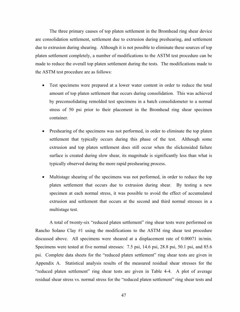
Appendix A. Statistical analysis results of the measured residual shear stresses for the
“reduced platen settlement” ring shear tests are given in Table 4-4. A plot of average
residual shear stress vs. normal stress for the “reduced platen settlement” ring shear tests and
48
the “ASTM standard” ring shear tests is given in Figure 4-4. Statistical analysis results of the
measured secant residual friction angles for the “reduced platen settlement” ring shear tests
are given in Table 4-5. A plot of average secant friction angle vs. normal stress for the
“reduced platen settlement” ring shear tests and the “ASTM standard” ring shear tests is
given in Figure 4-5. Figure 4-5 also shows the minimum and maximum secant residual
friction angles measured at each normal stress.
Table 4-4: Residual Shear Stresses Measured in “Reduced Platen Settlement” Ring Shear Tests on Rancho Solano Clay #1
Normal Stress (psi)
Number of Tests
Performed
Average Residual
Shear Stress (psi)
Standard Deviation of Measured
Residual Shear Stress (psi)
Minimum Measured Residual Shear Stress (psi)
Maximum Measured Residual Shear
Stress (psi)
7.5 7 2.7 0.14 2.5 2.9
14.6 4 5.2 0.12 5.1 5.3
28.8 4 9.9 0.22 9.6 10.1
50.1 6 16.6 0.47 16.1 17.3
85.6 5 27.3 0.76 26.6 28.3
0
10
20
30
0 10 20 30 40 50 60 70 80 90Normal Stress (psi)
She
ar S
tress
(psi
)
ASTM Standard Ring Shear TestReduced Platen Settlement Ring Shear Test
Figure 4-4. Residual shear stresses measured in “reduced platen settlement” ring shear
tests on Rancho Solano Clay #1.

49
Table 4-5: Values of Secant Residual Friction Angle Measured in “Reduced Platen Settlement” Ring Shear Tests on Rancho Solano Clay #1
Normal Stress (atm)
Number of Tests
Performed
Average Secant
Residual Friction Angle
(degrees)
Standard Deviation of Measured
Secant Residual Friction Angle
(degrees)
Minimum Measured Secant Residual Friction Angle (degrees)
Maximum Measured Secant Residual Friction Angle (degrees)
0.5 7 19.7 1.0 18.6 20.8
1.0 4 19.5 0.4 19.1 19.9
2.0 4 18.9 0.4 18.4 19.3
3.4 6 18.3 0.5 17.9 19.1
5.8 5 17.7 0.5 17.2 18.3
16
17
18
19
20
21
22
23
24
25
26
0.1 1.0 10.0Normal Stress (atm)
Sec
ant r
esid
ual f
rictio
n an
gle
(deg
rees
)
ASTM Standard Ring Shear Test
Reduced Platen Settlement Ring Shear Test
Figure 4-5. Values of secant residual friction angle measured in “reduced platen
settlement” ring shear tests on Rancho Solano Clay #1.
The data presented in Figure 4-4 and Figure 4-5 shows the significant effect that wall
friction has on residual strengths measured in the Bromhead ring shear device. These results
show that the “reduced platen settlement” test approach reduces these wall friction effects.
However, even if the “reduced platen settlement” test approach is used, wall friction in the
Bromhead ring shear device will continue to affect measurements of the residual strength,
because the procedure does not eliminate settlement of the top platen into the specimen
container.
50
Effect of Device Modifications on the Drained Residual Shear Strength of Rancho Solano Clay #1
In order to check the accuracy of the residual strengths measured using the “reduced
platen settlement” test approach, a series of drained ring shear tests was conducted on
Rancho Solano Clay #1 using a modified Bromhead ring shear device designed to reduce the
effects of wall friction.
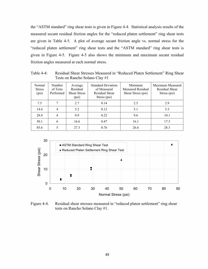
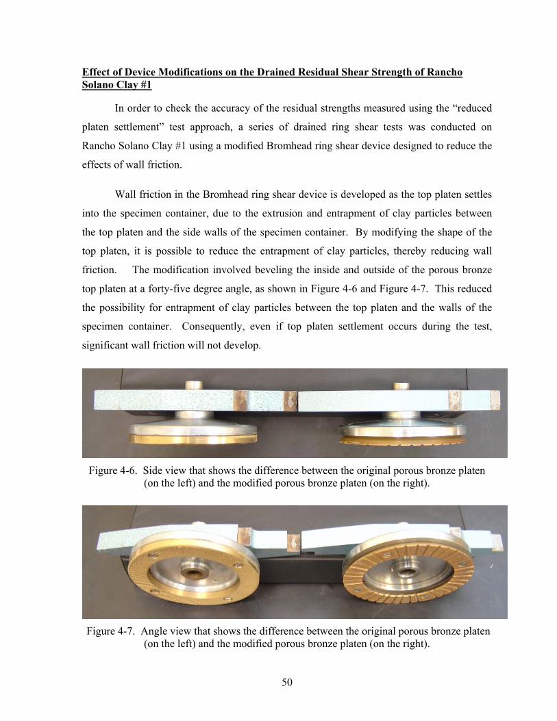
Wall friction in the Bromhead ring shear device is developed as the top platen settles
into the specimen container, due to the extrusion and entrapment of clay particles between
the top platen and the side walls of the specimen container. By modifying the shape of the
top platen, it is possible to reduce the entrapment of clay particles, thereby reducing wall
friction. The modification involved beveling the inside and outside of the porous bronze
top platen at a forty-five degree angle, as shown in Figure 4-6 and Figure 4-7. This reduced
the possibility for entrapment of clay particles between the top platen and the walls of the
specimen container. Consequently, even if top platen settlement occurs during the test,
significant wall friction will not develop.
Figure 4-6. Side view that shows the difference between the original porous bronze platen
(on the left) and the modified porous bronze platen (on the right).
Figure 4-7. Angle view that shows the difference between the original porous bronze platen
(on the left) and the modified porous bronze platen (on the right).
51
Twenty-six “modified platen” ring shear tests were performed on Rancho Solano
Clay #1 using the “reduced platen settlement” test procedure in combination with the
modification to the top platen described above. All specimens were sheared at a
displacement rate of 0.00071 in/min. Specimens were tested at five normal stresses: 7.5 psi,
14.6 psi, 28.8 psi, 50.1 psi, and 85.6 psi. Complete data sheets for the “modified platen” ring
shear tests are given in Appendix A.
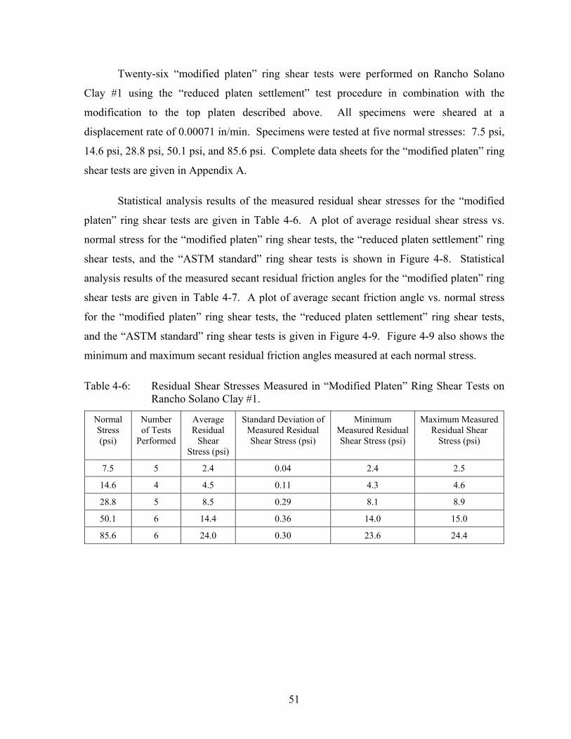
Statistical analysis results of the measured residual shear stresses for the “modified
platen” ring shear tests are given in Table 4-6. A plot of average residual shear stress vs.
normal stress for the “modified platen” ring shear tests, the “reduced platen settlement” ring
shear tests, and the “ASTM standard” ring shear tests is shown in Figure 4-8. Statistical
analysis results of the measured secant residual friction angles for the “modified platen” ring
shear tests are given in Table 4-7. A plot of average secant friction angle vs. normal stress
for the “modified platen” ring shear tests, the “reduced platen settlement” ring shear tests,
and the “ASTM standard” ring shear tests is given in Figure 4-9. Figure 4-9 also shows the
minimum and maximum secant residual friction angles measured at each normal stress.
Table 4-6: Residual Shear Stresses Measured in “Modified Platen” Ring Shear Tests on Rancho Solano Clay #1.
Normal Stress (psi)
Number of Tests
Performed
Average Residual
Shear Stress (psi)
Standard Deviation of Measured Residual Shear Stress (psi)
Minimum Measured Residual Shear Stress (psi)
Maximum Measured Residual Shear
Stress (psi)
7.5 5 2.4 0.04 2.4 2.5
14.6 4 4.5 0.11 4.3 4.6
28.8 5 8.5 0.29 8.1 8.9
50.1 6 14.4 0.36 14.0 15.0
85.6 6 24.0 0.30 23.6 24.4

52
0
10
20
30
0 10 20 30 40 50 60 70 80 90Normal Stress (psi)
She
ar S
tress
(psi
)ASTM Standard Ring Shear TestReduced Platen Settlement Ring Shear TestModified Platen Ring Shear Test
Figure 4-8. Residual shear stresses measured in “modified platen” ring shear tests on
Rancho Solano Clay #1.
Table 4-7: Values of Secant Residual Friction Angle Measured in “Modified Platen” Ring Shear Tests on Rancho Solano Clay #1
Normal Stress (atm)
Number of Tests
Performed
Average Secant Residual
Friction Angle (degrees)
Standard Deviation of Measured Secant
Residual Friction Angle (degrees)
Minimum Measured Secant Residual Friction Angle (degrees)
Maximum Measured Secant Residual Friction Angle (degrees)
0.5 5 18.0 0.3 17.5 18.3
1.0 4 17.0 0.4 16.4 17.3
2.0 5 16.5 0.5 15.8 17.1
3.4 6 16.0 0.4 15.7 16.7
5.8 6 15.7 0.2 15.4 15.9
The data presented in Figure 4-8 and Figure 4-9 shows that the “modified platen” ring
shear tests minimize the effect of wall friction in the Bromhead ring shear device, producing
more accurate measurements of the drained residual strength than the “reduced platen
settlement” test approach. Therefore, it appears that the most accurate results are achieved
using the “modified platen” approach, which uses the “reduced platen settlement” test
procedure in combination with the modified platen. The drained residual strength envelope
for Rancho Solano Clay #1 determined using this technique is shown in Figure 4-10. This
nonlinear failure envelope passes through the origin. The nonlinearity of the drained residual
strength failure envelope agrees well with test data collected by other researchers (Stark and
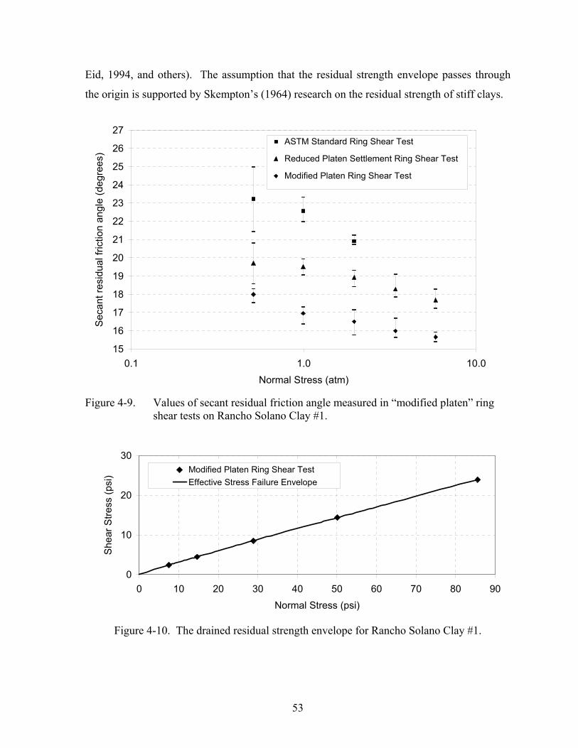
53
Eid, 1994, and others). The assumption that the residual strength envelope passes through
the origin is supported by Skempton’s (1964) research on the residual strength of stiff clays.
15
16
17
18
19
20
21
22
23
24
25
26
27
0.1 1.0 10.0Normal Stress (atm)
Sec
ant r
esid
ual f
rictio
n an
gle
(deg
rees
)
ASTM Standard Ring Shear Test
Reduced Platen Settlement Ring Shear Test
Modified Platen Ring Shear Test
S
Figure 4-9. Values of secant residual friction angle measured in “modified platen” ring
shear tests on Rancho Solano Clay #1.
0
10
20
30
0 10 20 30 40 50 60 70 80 90Normal Stress (psi)
She
ar S
tress
(psi
) Modified Platen Ring Shear TestEffective Stress Failure Envelope
Figure 4-10. The drained residual strength envelope for Rancho Solano Clay #1.

54
One drawback to the “modified platen” test approach is the amount of soil extruded
during shear. Because the top platen is beveled to reduce wall friction, there is less resistance
to soil extrusion between the top platen and the side walls of the specimen container.
Therefore, soil extrusion occurs more rapidly during shear, and the amount of specimen
extruded during a test can be very significant. This limits the total shear displacement that
can be applied to a specimen, because it is possible to extrude the entire specimen during
shear. Additionally, since the amount of vertical displacement that occurs during shear is
primarily controlled by the amount of soil extruded, measurements of vertical displacement
cannot be correlated to change in soil volume or void ratio.
The Drained Residual Shear Strength of Rancho Solano Clay #2
The drained residual shear strength of Rancho Solano Clay #2 was measured using
the “modified platen” ring shear test procedure described in the previous section.
A total of 15 “modified platen” ring shear tests were performed on Rancho Solano
Clay #2. All specimens were sheared at a displacement rate of 0.00071 in/min. Specimens
were tested at four normal stresses: 7.5 psi, 14.6 psi, 28.8 psi, and 50.1 psi. Complete data
sheets for these ring shear tests are given in Appendix A. Statistical analysis results of the
measured residual shear stresses are given in Table 4-8. A plot of average residual shear
stresses vs. testing normal stresses is given in Figure 4-11. Statistical analysis results of the
measured secant residual friction angles are given in Table 4-9. A plot of average secant
friction angles vs. normal stresses is given in Figure 4-12. Figure 4-12 also shows the
minimum and maximum secant residual friction angles measured at each normal stress.
Table 4-8: Residual Shear Stresses Measured in “Modified Platen” Ring Shear Tests on Rancho Solano Clay #2.
Normal Stress (psi)
Number of Tests
Performed
Average Residual
Shear Stress (psi)
Standard Deviation of Measured Residual Shear Stress (psi)
Minimum Measured Residual Shear Stress (psi)
Maximum Measured Residual Shear
Stress (psi)
7.5 9 3.3 0.30 2.8 3.6
14.6 3 5.8 0.25 5.6 6.1
28.8 1 10.6 N/A N/A N/A
50.1 2 17.1 0.25 16.9 17.2

55
0
10
20
30
0 10 20 30 40 50 60Normal Stress (psi)
She
ar S
tress
(psi
)
Modified Platen Ring Shear Test
Figure 4-11. Residual shear stresses measured in “modified platen” ring shear tests on
Rancho Solano Clay #2.
Table 4-9: Values of Secant Residual Friction Angle Measured in “Modified Platen” Ring Shear Tests on Rancho Solano Clay #2
Normal Stress (atm)
Number of Tests
Performed
Average Secant Residual
Friction Angle (degrees)
Standard Deviation of Measured Secant
Residual Friction Angle (degrees)
Minimum Measured Secant Residual Friction Angle (degrees)
Maximum Measured Secant Residual Friction Angle (degrees)
0.5 9 23.7 1.9 20.7 25.7
1.0 3 21.7 0.9 21.0 22.7
2.0 1 20.3 N/A N/A N/A
3.4 2 18.8 0.3 18.6 19.0
181920212223242526
0.1 1.0 10.0Normal Stress (atm)
Sec
ant r
esid
ual f
rictio
n an
gle
(deg
rees
)
Modified Platen Ring Shear Test
Figure 4-12. Values of secant residual friction angle measured in “modified platen” ring
shear tests on Rancho Solano Clay #2.

56
Analysis of the data in Table 4-8, Table 4-9, Figure 4-11 and Figure 4-12 indicates
that the residual strength failure envelope for Rancho Solano Clay #2 is nonlinear.
Additionally, there is consistency between the residual strength values measured in each of
the ring shear devices, which gives confidence in the measured drained residual strengths.
Based on the test results, a drained residual strength envelope can be constructed using the
same approach that was used for Rancho Solano Clay #1. The resulting drained residual
strength envelope for Rancho Solano Clay #2 is shown in Figure 4-13.
0
10
20
30
0 10 20 30 40 50 60Normal Stress (psi)
She
ar S
tress
(psi
) Modified Platen Ring Shear TestEffective Stress Failure Envelope
Figure 4-13. The drained residual strength envelope for Rancho Solano Clay #2.
The Drained Residual Shear Strength of San Francisco Bay Mud
Ring shear tests were also used to measure the drained residual shear strength of San
Francisco Bay Mud. A total of twelve “modified platen” ring shear tests were performed on
San Francisco Bay Mud using the “reduced platen settlement” test procedure and the
modified platen. All specimens were sheared at a displacement rate of 0.00071 in/min.
Specimens were tested at five normal stresses: 7.5 psi, 14.6 psi, 28.8 psi, 50.1 psi, and 85.6
psi. Complete data sheets for these ring shear tests are given in Appendix A. Statistical
analysis results of the measured residual shear stresses for these ring shear tests are given in
Table 4-10. A plot of average residual shear stress vs. normal stress for these ring shear tests
is given in Figure 4-14. Statistical analysis results of the measured secant residual friction
angles are given in Table 4-11. A plot of average secant friction angle vs. normal stress is
57
given in Figure 4-15. Figure 4-15 also shows the minimum and maximum secant residual
friction angles measured at each normal stress.
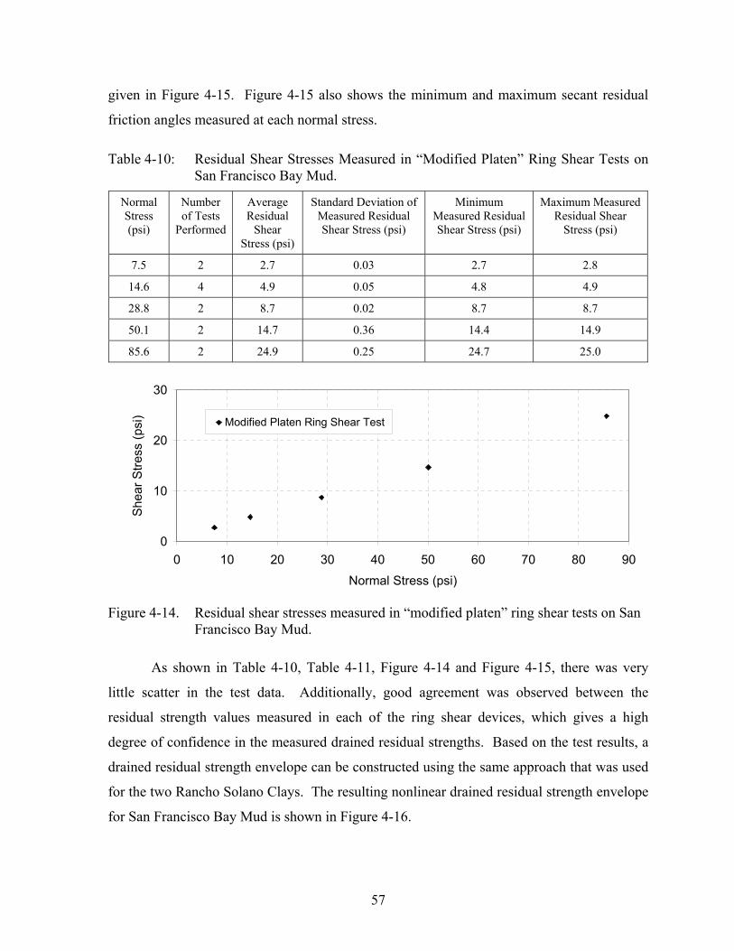
Table 4-10: Residual Shear Stresses Measured in “Modified Platen” Ring Shear Tests on San Francisco Bay Mud.
Normal Stress (psi)
Number of Tests
Performed
Average Residual
Shear Stress (psi)
Standard Deviation of Measured Residual Shear Stress (psi)
Minimum Measured Residual Shear Stress (psi)
Maximum Measured Residual Shear
Stress (psi)
7.5 2 2.7 0.03 2.7 2.8
14.6 4 4.9 0.05 4.8 4.9
28.8 2 8.7 0.02 8.7 8.7
50.1 2 14.7 0.36 14.4 14.9
85.6 2 24.9 0.25 24.7 25.0
0
10
20
30
0 10 20 30 40 50 60 70 80 90Normal Stress (psi)
She
ar S
tress
(psi
) Modified Platen Ring Shear Test
Figure 4-14. Residual shear stresses measured in “modified platen” ring shear tests on San
Francisco Bay Mud.
As shown in Table 4-10, Table 4-11, Figure 4-14 and Figure 4-15, there was very
little scatter in the test data. Additionally, good agreement was observed between the
residual strength values measured in each of the ring shear devices, which gives a high
degree of confidence in the measured drained residual strengths. Based on the test results, a
drained residual strength envelope can be constructed using the same approach that was used
for the two Rancho Solano Clays. The resulting nonlinear drained residual strength envelope
for San Francisco Bay Mud is shown in Figure 4-16.

58
Table 4-11: Values of Secant Residual Friction Angle Measured in “Modified Platen” Ring Shear Tests on San Francisco Bay Mud
Normal Stress (atm)
Number of Tests
Performed
Average Secant Residual
Friction Angle (degrees)
Standard Deviation of Measured Secant
Residual Friction Angle (degrees)
Minimum Measured Secant Residual Friction Angle (degrees)
Maximum Measured Secant Residual Friction Angle (degrees)
0.5 2 20.1 0.2 19.9 20.2
1.0 4 18.4 0.2 18.2 18.6
2.0 2 16.8 0.04 16.8 16.9
3.4 2 16.3 0.4 16.1 16.6
5.8 2 16.2 0.2 16.1 16.3
15
16
17
18
19
20
21
0.1 1.0 10.0Normal Stress (atm)S
ecan
t res
idua
l fric
tion
angl
e (d
egre
es)
Modified Platen Ring Shear Test
Figure 4-15. Values of secant residual friction angle measured in “modified platen” ring
shear tests on San Francisco Bay Mud.
0
10
20
30
0 10 20 30 40 50 60 70 80 90Normal Stress (psi)
She
ar S
tress
(psi
) Modified Platen Ring Shear TestEffective Stress Failure Envelope
Figure 4-16. The drained residual strength envelope for San Francisco Bay Mud.

59
The Fast Residual Shear Strength of Rancho Solano Clay #1
As part of the ring shear testing program for Rancho Solano Clay #1, a series of fast
ring shear tests were also conducted in the Bromhead ring shear device. The purpose of
these tests was to try to develop an understanding of the fast residual shear strength along
existing slickensided discontinuities.
Although it is not possible to control boundary drainage conditions directly in the
Bromhead ring shear device, it was hoped that fast shearing would provide reasonably
accurate measurements of undrained strength along the slickensided surface. This appears to
be a reasonable expectation because dissipation of shear-induced pore pressures is inhibited
by the low permeability of the clay soil, combined with the short test duration.
The fast residual ring shear testing program was developed using the same rationale
and test approach that was first proposed by Skempton (1985) for fast-shear testing in the
NGI-type ring shear device. Using Skempton’s (1985) approach, a clay specimen is first
sheared slowly to create a slickensided failure surface, then sheared rapidly to measure the
undrained shearing response along the slickensided shear surface, and then slowly again to
re-establish the drained residual condition. This approach has also been employed
successfully by other researchers using the NGI-type ring shear device (Lemos et al, 1985;
Tika et al, 1996; Vesseley and Cornforth, 1998; and Tika and Hutchinson, 1999), as
discussed in Chapter 2. The usefulness of this test approach for measuring fast residual
strengths in the Bromhead ring shear device has not been explored.
In order to measure the fast residual shear strength along slickensided surfaces in
Rancho Solano Clay #1, it was first necessary to create a slickensided failure surface within
the ring shear test specimen. Slickensided failure surfaces were created in the ring shear
specimens by preparing and testing specimens using the “modified platen approach”. For
each fast shear test, initial drained shearing was performed at a displacement rate of 0.00071
in/min (Stage 1 shearing), to create a slickensided failure surface within the ring shear test
specimen.
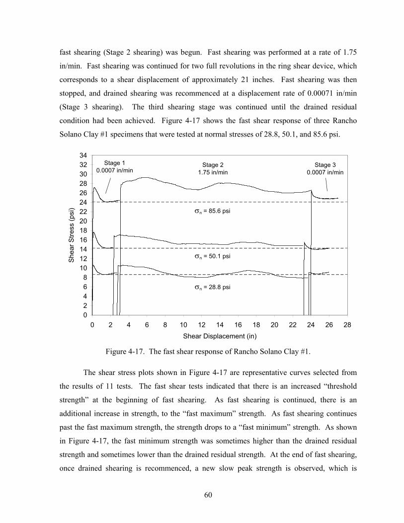
During a typical fast shear test, the initial drained shearing stage was continued until
the residual condition had been reached. At that point, drained shearing was stopped, and
60
fast shearing (Stage 2 shearing) was begun. Fast shearing was performed at a rate of 1.75
in/min. Fast shearing was continued for two full revolutions in the ring shear device, which
corresponds to a shear displacement of approximately 21 inches. Fast shearing was then
stopped, and drained shearing was recommenced at a displacement rate of 0.00071 in/min
(Stage 3 shearing). The third shearing stage was continued until the drained residual
condition had been achieved. Figure 4-17 shows the fast shear response of three Rancho
Solano Clay #1 specimens that were tested at normal stresses of 28.8, 50.1, and 85.6 psi.
02468
10121416182022242628303234
0 2 4 6 8 10 12 14 16 18 20 22 24 26 28Shear Displacement (in)
She
ar S
tress
(psi
)
Stage 2 1.75 in/min
Stage 1 0.0007 in/min
Stage 3 0.0007 in/min
σn = 85.6 psi
σn = 50.1 psi
σn = 28.8 psi
Figure 4-17. The fast shear response of Rancho Solano Clay #1.
The shear stress plots shown in Figure 4-17 are representative curves selected from
the results of 11 tests. The fast shear tests indicated that there is an increased “threshold
strength” at the beginning of fast shearing. As fast shearing is continued, there is an
additional increase in strength, to the “fast maximum” strength. As fast shearing continues
past the fast maximum strength, the strength drops to a “fast minimum” strength. As shown
in Figure 4-17, the fast minimum strength was sometimes higher than the drained residual
strength and sometimes lower than the drained residual strength. At the end of fast shearing,
once drained shearing is recommenced, a new slow peak strength is observed, which is

61
higher than the drained residual strength. The strength then drops again to the drained
residual strength, which coincides with the initial drained residual strength.
These results agree in most respects with what has been observed for clayey soils in
the NGI-type ring shear apparatus (Lemos et al., 1985; Tika et al, 1996; Vesseley and
Cornforth, 1998; and Tika and Hutchinson, 1999). However, there is one significant
difference between the fast minimum shear behavior in the Bromhead ring shear device and
what has been observed in the NGI-type ring shear device. This difference is the cyclic up-
and-down nature of the stress-displacement curve, which is clearly evident in Figure 4-17.
This cyclic increase and decrease in shear stress is probably not a true soil behavior
phenomenon, and could be caused by either of the following mechanisms:
One possibility is the replacement of soil particles along the shearing plane, which
might occur as follows: As soil is extruded from the shearing plane, oriented clay particles
are replaced by clay particles that have not been completely sheared to the residual condition.
The strength of these non-oriented particles would be higher, and additional shearing would
be necessary to orient the particles along the shearing plane. Cycles of clay particle
extrusion, replacement by non-oriented particles, and orientation of clay particles along the
shearing plane might cause variations in the measured shear stress. Unfortunately, the top
platen modifications that are necessary to reduce wall friction in the Bromhead ring shear
device also allow soil extrusion at a more rapid rate than usual, which would exacerbate this
behavior, if it does occur.
A second possible mechanism for the observed “pumping” behavior is a machine
effect that may be caused by subtle shifting of the top platen during shear. Figure 4-18
shows the fast shear response of a Rancho Solano Clay #1 specimen that was sheared to large
displacements in the Bromhead ring shear device. The observed peaks and troughs in the
stress-displacement curve occur on a cyclic basis, with approximately one full revolution
(360°) of the specimen between successive peaks in the measured shear stress. This strongly
suggests that the cyclic increase and decrease in measured shear resistance is a machine
effect, probably wobbling of the top platen, and does not represent real soil behavior.

62
This phenomenon makes it impossible to quantify the value of the fast minimum
residual strength. Even from a qualitative standpoint, in some cases it is not clear whether
the fast minimum strength is higher than or lower than the drained residual strength (as
shown by the σn = 28.8 psi test in Figure 4-17).
10
12
14
16
18
20
0 10 20 30 40 50 60 70Shear Displacement (in)
She
ar S
tress
(psi
)
σn = 50.1 psi
Stage 1 0.0007 in/min
Stage 2 1.75 in/min
360° 360° 360° 360° 360° 360°
Figure 4-18. The fast shear response of Rancho Solano Clay #1 sheared to large
displacements in the Bromhead ring shear device.
In addition to the physical problems of extrusion and top platen shifting during fast
shear tests, there is also one significant theoretical problem with using the Bromhead ring
shear device to measure the fast strength of clays. This has to do with the pore pressure
response of the soil surrounding the slickensided failure plane.
As discussed in Chapter 2, Skempton (1985) has shown that rapid shearing along
pre-existing slickensided discontinuities can lead to significant gains in strength above the
drained residual strength condition. Skempton (1985) hypothesized that this strength gain is
due to disturbance of the originally ordered clay particles, which causes a transition from the
sliding mode to the turbulent mode of failure. As the clay particles along the shearing plane
are disturbed, negative pore pressures are developed along the shearing plane, which leads to
the development of a negative pore pressure gradient into the surrounding soil. These
negative pore pressures are dissipated as shear continuous, which is what causes a decrease
in strength from the “fast maximum” condition to the “fast minimum” condition.

63
With the NGI-type ring shear device (used by Skempton and others for fast ring shear
testing), there is a significant amount of clay on either side of the failure plane. The presence
of this clay is essential for the development of negative pore pressures along the failure plane
during fast shear. However, in the Bromhead ring shear device, shearing takes place at or
very close to the top platen. Therefore, the drainage path length from the shearing plane to
the closest free-draining boundary is very short, and any negative pore pressures developed
are dissipated relatively quickly. This leads to a pore pressure response that is different than
what would occur in the field, or in the NGI-type ring shear device. Consequently, the fast
residual strengths measured in the Bromhead ring shear device may not match the fast-shear
strengths in the field or in the NGI-type ring shear device.
In conclusion, a number of practical and theoretical problems are involved in using
the Bromhead ring shear device to measure fast residual shear strengths. Consequently, the
fast ring shear test results for Rancho Solano Clay #1 were discarded, and the fast ring shear
testing program was discontinued. The NGI-type ring shear device appears to be better
suited for this type of test.
Top Related