Dynamic Tests on Ring Shear Apparatus - IAENG · upgrade of a ring shear apparatus to perform this...
5
Abstract— Ring shear apparatus are used to determine the ultimate shear strength of soils when it is sheared to large displacements. Since recent investigations have shown that the soil ultimate strength can rise, if sheared by a large intermittent movement, the paper describes the peculiarities of these tests and the upgrade of a ring shear apparatus to perform this test. In the final part of the paper, the first experimental results are reported and commented. Index Terms — cyclic rotation, ring shear apparatus, soil, ultimate strength I. INTRODUCTION ing shear apparatus allows to evaluate the residual shear strength of soils also termed the ultimate shear strength. This is the strength of soil when it is sheared to large displacements, for example along the failure plane of a landslide or in a fault zone [1, 2]. To determine ultimate shear strength value, the ring apparatus consolidates a thick sample to the required stress. A slip surface is formed in the sample as part of the test procedure. The sample is displaced between two rings (Fig. 1): the upper one is fixed while the lower one, driven by an electric motor, rotates at a constant speed. A continuous shearing action is so applied to the sample until the constant residual strength value is achieved. Fig.1. Ring shear operating principle Recent investigations [3] have shown that in clay formations, the co-seismic reactivation of pre-existing landslides involves dynamic shear actions on sliding surfaces characterised by attritive states. Manuscript received April, 2015; G. Di Massa is with the University of Naples Federico II, Italy (e-mail: gdimassa@ unina.it). S. Pagano is with the University of Naples Federico II, Italy (e-mail: pagano@ unina.it). M. Ramondini is with the University of Naples Federico II, Italy (e- mail: massimo.ramondini@ unina.it) To put in evidence this peculiarity, an intermittent rotating motions must be applied to the lower ring, after the attainment of fully softened and residual conditions. The paper describes the upgrade of a ring shear apparatus that has been equipped with an electric motor by which it is possible to adjust the characteristics of the intermittent motion of the ring below. The test rig will perform an extensive test campaign to evaluate the combination of the motion characteristics and the vertical load able to maximize the ultimate shear strength. By way of example, in the final part of the paper, some preliminary tests are shown and commented. II. EQUIPMENT DESCRIPTION The soil testing equipment adopted for this kind of tests is the Wykeham Farrance mod. 25850 that, in its original configuration, is constituted by (Fig. 2-5): - a rotating sample container or shear box, placed in the lower part of the sample turret, characterized by an annular groove whose mean diameter is equal to 85 mm, filled with the soil sample. The sample container (lower ring) is driven by an electric motor by means of a mechanical transmission that, in turn, is constituted by a gearbox with 5 gears, a gear with interchangeable wheels, a chain drive transmission and, finally, by a worm drive whose wheel is connected to the sample container. On one extremity of the worm shaft it is spliced the sprocket- wheel of the chain drive; on the other extremity there is an hand-wheel that allows to adjust the initial angular position of the sample container to a “datum point”; Changing the gear ratio value, the sample container can rotate in the following rotating velocity range: 0.25–60 deg/min. The correspondent translational speed, at the medium sample diameter, ranges from 0.18 to 44.5 mm/min. The container rotating speed can be maintained constant independently from the vertical load acting on the sample and, therefore, independently from the resistant actions exerted by sample itself; - a loading device to impress an assigned constant vertical load to the sample. The sample is vertically compressed between two porous stones by means of a loading system constituted by several masses suspended at the extremity of the lever loading arm (Fig. 3). The loading joke transmits the amplified (10:1) load to the soil sample. The settlement of the upper plate during the consolidation phase and when is sheared, is monitored by means of a sensitive dial gauge or linear transducer bearing on the top of the Dynamic Tests on Ring Shear Apparatus G. Di Massa Member IAENG, S. Pagano, M. Ramondini R Proceedings of the World Congress on Engineering 2015 Vol II WCE 2015, July 1 - 3, 2015, London, U.K. ISBN: 978-988-14047-0-1 ISSN: 2078-0958 (Print); ISSN: 2078-0966 (Online) WCE 2015
Transcript of Dynamic Tests on Ring Shear Apparatus - IAENG · upgrade of a ring shear apparatus to perform this...
Abstract— Ring shear apparatus are used to determine the
ultimate shear strength of soils when it is sheared to large displacements.
Since recent investigations have shown that the soil ultimate strength can rise, if sheared by a large intermittent movement, the paper describes the peculiarities of these tests and the upgrade of a ring shear apparatus to perform this test. In the final part of the paper, the first experimental results are reported and commented.
Index Terms — cyclic rotation, ring shear apparatus, soil, ultimate strength
I. INTRODUCTION
ing shear apparatus allows to evaluate the residual shear strength of soils also termed the ultimate shear
strength. This is the strength of soil when it is sheared to large displacements, for example along the failure plane of a landslide or in a fault zone [1, 2].
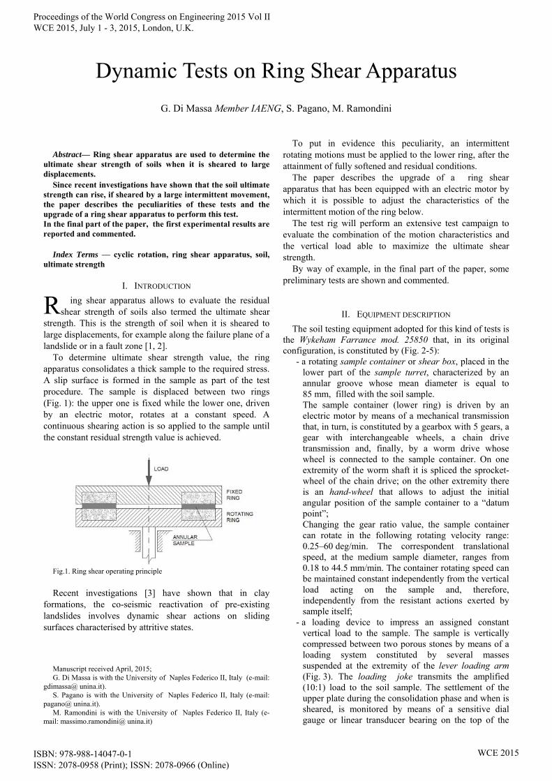
To determine ultimate shear strength value, the ring apparatus consolidates a thick sample to the required stress. A slip surface is formed in the sample as part of the test procedure. The sample is displaced between two rings (Fig. 1): the upper one is fixed while the lower one, driven by an electric motor, rotates at a constant speed. A continuous shearing action is so applied to the sample until the constant residual strength value is achieved.
Fig.1. Ring shear operating principle
Recent investigations [3] have shown that in clay
formations, the co-seismic reactivation of pre-existing landslides involves dynamic shear actions on sliding surfaces characterised by attritive states.
Manuscript received April, 2015; G. Di Massa is with the University of Naples Federico II, Italy (e-mail:
gdimassa@ unina.it). S. Pagano is with the University of Naples Federico II, Italy (e-mail:
pagano@ unina.it). M. Ramondini is with the University of Naples Federico II, Italy (e-
mail: massimo.ramondini@ unina.it)
To put in evidence this peculiarity, an intermittent rotating motions must be applied to the lower ring, after the attainment of fully softened and residual conditions.
The paper describes the upgrade of a ring shear apparatus that has been equipped with an electric motor by which it is possible to adjust the characteristics of the intermittent motion of the ring below.
The test rig will perform an extensive test campaign to evaluate the combination of the motion characteristics and the vertical load able to maximize the ultimate shear strength.
By way of example, in the final part of the paper, some preliminary tests are shown and commented.
II. EQUIPMENT DESCRIPTION
The soil testing equipment adopted for this kind of tests is the Wykeham Farrance mod. 25850 that, in its original configuration, is constituted by (Fig. 2-5):
- a rotating sample container or shear box, placed in the lower part of the sample turret, characterized by an annular groove whose mean diameter is equal to 85 mm, filled with the soil sample. The sample container (lower ring) is driven by an electric motor by means of a mechanical transmission that, in turn, is constituted by a gearbox with 5 gears, a gear with interchangeable wheels, a chain drive transmission and, finally, by a worm drive whose wheel is connected to the sample container. On one extremity of the worm shaft it is spliced the sprocket-wheel of the chain drive; on the other extremity there is an hand-wheel that allows to adjust the initial angular position of the sample container to a “datum point”; Changing the gear ratio value, the sample container can rotate in the following rotating velocity range: 0.25–60 deg/min. The correspondent translational speed, at the medium sample diameter, ranges from 0.18 to 44.5 mm/min. The container rotating speed can be maintained constant independently from the vertical load acting on the sample and, therefore, independently from the resistant actions exerted by sample itself;
- a loading device to impress an assigned constant vertical load to the sample. The sample is vertically compressed between two porous stones by means of a loading system constituted by several masses suspended at the extremity of the lever loading arm (Fig. 3). The loading joke transmits the amplified (10:1) load to the soil sample. The settlement of the upper plate during the consolidation phase and when is sheared, is monitored by means of a sensitive dial gauge or linear transducer bearing on the top of the
Dynamic Tests on Ring Shear Apparatus
G. Di Massa Member IAENG, S. Pagano, M. Ramondini
R
Proceedings of the World Congress on Engineering 2015 Vol II WCE 2015, July 1 - 3, 2015, London, U.K.
ISBN: 978-988-14047-0-1 ISSN: 2078-0958 (Print); ISSN: 2078-0966 (Online)
WCE 2015

load hanger; - a torque arm assembly, placed in the upper part of the
sample turret which prevents upper ring rotation due to the shear actions exerted by the soil sample; the torque arm is constrained by means of to force sensors through which it is possible to measure the friction torque;
- two force sensors, each constituted by a deformable ring and a mechanical comparator to detect the ring deformation (load rings, ext=178 mm; thick = 3 mm); in the current equipment configuration the comparators have been replaced with two LVDT sensors that can measure up to 500 N.
Fig. 2. Friction force measurement
Fig. 3. Ring shear apparatus side view
Fig. 4. Ring shear apparatus plan view
Fig. 5. Ring shear mechanical transmission
III. EQUIPMENT UPGRADE
To move the sample container with an intermittent rotating law motion, the apparatus was equipped with a servomotor joined to the worm shaft, by means of an helical joint, in
place of the hand-wheel, as schematically represented in Fig. 6. When the servomotor operates, the chain drive must be disconnected. The servomotor installation did not require any irreversible changes of the equipment; its bracket (constituted by two aluminum alloy components, for mounting reasons) was connected to the frame machine adopting the threaded holes of the protecting cover of the shaft rolling bearing (Fig. 7). A hole, drilled on the lateral bracket surface, allows to screw the helical joint on the worm shaft.
Fig. 6. Servomotor installation
Fig. 7. Servomotor mounting
IV. SAMPLE CONTAINER MOTION
The servomotor drives the sample container so that it can perform an intermittent motion. The motion law considered in the following is characterized by a profile velocity that has an initial trapezoidal form, followed by a time interval during which the container is at rest (Fig. 8).
Fig. 8. Desired velocity profile
The sample annular housing has a mean radius (R) of about 42.5 mm; the two force sensors, adopted to detect the sample shear resistance, exert their reactions on the (160
Proceedings of the World Congress on Engineering 2015 Vol II WCE 2015, July 1 - 3, 2015, London, U.K.
ISBN: 978-988-14047-0-1 ISSN: 2078-0958 (Print); ISSN: 2078-0966 (Online)
WCE 2015

mm long) torque arm. The sensor have a full-scale range of 500 N and therefore, the maximum measurable torque is equal to about: Mr = 80 Nm. To choose the power of the electric motor it was assumed that the maximum compressive stress, provided by the loading device is equal to 3 daN/cm2 and that the maximum coefficient of friction provided by the soil sample is equal to 0.6 ( = 33°). The maximum friction torque exerted by the soil sample, whose annular cross section (A) is equal to 40 cm2, results therefore:
ApfRM r =30 Nm.
The mechanical transmission between servomotor and sample container is constituted by a worm drive with a 55:1 gear ratio (ratio between the number of teeth of the worm wheel and the number of worm threads). The maximum torque, reduced to the servomotor axis, is: Mrm = 30/55 = 0.54 Nm. The reference intermittent motion is characterized by the following values: linear acceleration: α = 0.25÷0.45 g ; mean linear velocity: v = 1÷10 mm/s; frequency = 1÷10 Hz. The servomotor power was chosen considering a tangential acceleration for the annular sample equal to: a = 4.5 m/s2. The correspondent angular acceleration of the sample container and of the servomotor are respectively: = a/R = 113 rad/s2 ; m= ∙ = 6160 rad/s2. In the following, it is neglected the moment of inertia of the sample container and of the worm wheel. In fact, their reduced values are very small in comparison of other inertias. Considering servomotor rotor and worm inertia, equal to about I = 0.7∙10-4 kgm2, the inertia torque is equal to: MI = 0.7∙10-4 ∙6160 = 0.43 Nm. The maximum torque that the servomotor must provide is therefore: Mtot = MI + Mrm = 0.43+0.54 ≈ 1.0 Nm
To define the maximum rotating speed for the servomotor it must be considered the most demanding operating cycle is characterized by the following parameters: angular acceleration: =a/R=4.5/0.04=113 rad/s2; mean linear velocity: vm = 10 mm/s = 0.010m/s; the
correspondent mean angular velocity is: m = vm /R = 0.010/0.04 =0.25 rad/s
cycle frequency: f=1 Hz (T = 1.0 s). Considering the gear ratio of the mechanical transmission ( = 55), in the following table the main kinematic
parameters for the sample container and for the servomotor are summarized:
Shear box servomotor Angular acceleration
= 112.5 rad/s2
M = 6187 rad/s2
Mean angular velocity
m =0.25 rad/s
m,M = 13.75 rad/s
rotations per cycle (with: T=1 s)
= 0.25 rad (= 14.3°)
M = 13.75 rad (= 788° = 2.2 rev)
Tab. I. Kinematic parameters
The maximum rotation speed is reached for the velocity profile reported in Fig. 9, characterized by a triangular shape diagram of the first part of the cycle (degeneration of the trapezoidal profile) followed by a zero velocity value.
Fig. 9. Velocity profile with maximum rotation speed The first part of the cycle ends for t=tf . For: t = tf /2, the angular velocity reaches its maximum value b. Adopting the kinematic parameters reported in Tab.I, it follows: a) b is reached with a constant acceleration, so that:
b = tt/2 = tt / 2 = 3094 tt; b) a complete cycle, having period of 1 s, involves a
servomotor rotation equal to: M = 13.75 rad. Taking into account the triangular shape law, the following two relationships may be obtained: M = ½ tt b = 13.75 rad; tt b = 27.5 rad.
It follows:
b = 291 rad/s ; tt = 0.094 s . The maximum inertia torque is practically equal to that already calculated: MI = I = 0.7∙10-4 ∙6187 = 0.43 Nm The worm gear mechanical efficiency could be estimated by means of the following expression:
p
rf
r
pf
21/
21
Being f the friction coefficient that in case of adequate lubrication can be assumed equal to 0.05, p the pitch of the
Proceedings of the World Congress on Engineering 2015 Vol II WCE 2015, July 1 - 3, 2015, London, U.K.
ISBN: 978-988-14047-0-1 ISSN: 2078-0958 (Print); ISSN: 2078-0966 (Online)
WCE 2015

worm thread and r the mean radius of the worm. As the gear ratio is equal to 55:1, the mechanical efficiency m was assumed equal to 0.4. The power required for the electric motor is therefore: P = Mtot* =1.0*291/0.40 = 728 W 3. Motor selection On the basis of the intermittent motion characteristics for the sample container a 930 W brushless servomotor was chosen (Kollmorgen, mod.:AKM24D-ACDNC-00 505573) having the following main characteristics:
- maximun rotating speed: 8000rpm; - maximum torque: 1.41Nm; - maximum current 2.21A; - voltage constant KErms =40,8 mVmin; - torque constant = 0,63 Nm/A - rotor inertia: 0.270 kg cm2; - shaft diameter: 9 mm.
In unloaded operating condition, it is found that the servomotor is able to follow the desired speed profile with good approximation (Fig. 10). In such condition the load is only due by the system rotating inertia; Fig.11 shows the corresponding motor torque curve.
Fig.10. Reference and effective velocity profile
Fig.11. Motor torque
In load operating condition the mechanical efficiency of the transmission between the motor and the container was evaluated; in steady-state condition, the torque provided by the electric motor was detected together with the one measured by the load rings; the mechanical efficiency
results equal to about 30%. So the maximum torque that the servomotor can deliver on the sample container is: Mmax = 1.41*55*0.3 = 23Nm A planetary gear box may be used for speed reduction and torque multiplication. There are specifically designed planetary gear box that can meet the motor mounting dimensions without any modification of the motor support (Fig.12). A self aligning hub is adopted to maintain concentricity between motor shaft and gear-head. For this gear box, the minimum gear ratio is 3:1 which would result in tripling of the torque acting on the sample container maintaining the maximum rotation speed at about 48 rpm. The correct gear ratio must be chosen through a tradeoff between the maximum torque and the maximum rotating speed of the sample container.
Fig.12. Servomotor with planetary gearbox
4. Tests and data acquisition Each test consists of three phases: the first phase is the standard one, during which the rotating sample container rotates at a constant speed fixed at 0.05mm/min and the torque slowly grows until it reaches an asymptotic value (the residual shear strength) usually reached after a displacement of 10 cm. Reached the asymptotic torque value, the second phase starts: the sample container is forced to rotate, according to the assigned intermittent law motion. In the third phase, similar to the first one, the rotating speed turns to be constant and an increase of the torque, with respect to the previous residual shear value, is expected. As said above, the friction torque exerted by the soil sample is detected by means of two load rings, each instrumented with an LVDT sensor. This measuring system has a good static characteristic but, due to the high deformability of the rings, when the input signal rapidly varies, it introduce the effects of the dynamic behavior of the rings, modifying the response. The sensor are so inadequate to follow the second phase of the test as it can excite the rings to vibrate altering the torque measure. As the aim of the test is to detect the torque only in the first and in the third test phases, which involves a quasi-static phenomenon, the use of the load rings may be considered acceptable.
In Fig. 13, two torque diagrams, for two different applied loads, are reported; the displacement scale was cutted around the impulsive load phase. In both cases, it can be noted an increase of the shear strength during the intermittent load phase; in the third phase a reduction of the
Proceedings of the World Congress on Engineering 2015 Vol II WCE 2015, July 1 - 3, 2015, London, U.K.
ISBN: 978-988-14047-0-1 ISSN: 2078-0958 (Print); ISSN: 2078-0966 (Online)
WCE 2015

shear strength was measured in the new final state characterized by strength value higher than those measured in the first phase. This behavior can be explained by assuming that the application of impulsive load induce a different arrangement of soil particles on the slip surface, with the formation of a new shearing surface. Opening a window around the second phase (Fig. 13), characterized by displacements of about 70 cm, it can be observed that during the impulsive load, shear stress value oscillations are influenced by the applied vertical load.
Fig.13. Residual shear stress ad different vertical load
Fig.14. Shear stress during phase 2
V. CONCLUSION
The first experimental tests performed on the updated equipment have shown its effectiveness for the study of the effects of shock loading on the residual strength of the clay soils. During the transient phase (phase 2), the deformability of the load rings does not allow a reliable measurement of shear stresses acting on the sample; therefore, to check if the intermittent motion of the sample container follows the desired law motion, the rig will be equipped with rigid load cells.
REFERENCES [1] G. Di Massa, L. Pagano, S. Pagano, M. Russo, R. Russo, C.
Zingariello,- A Mechanical Slope for Flowslide Investigations - World Congress on Engineering (WCE), (ISBN: 978-988-19252-7-5), pp.1376-1380, London, U.K., 2-4 July, 2014.
[2] G. Di Massa, L. Pagano, S. Pagano, M. Russo, R. Russo, C. Zingariello, Flowslide Investigations Test Rig Design, Springer Science+Business Media Dordrecht 2015 G.-C. Yang et al. (eds.), Transactions on Engineering Technologies, DOI 10.1007/978-94-017-9804-4_9
[3] Grelle G., Guadagno F. M., Shear mechanisms and viscoplastic effects during impulsive shearing. Géotechnique 60, n. 2, 2010, pp. 91–103.
Proceedings of the World Congress on Engineering 2015 Vol II WCE 2015, July 1 - 3, 2015, London, U.K.
ISBN: 978-988-14047-0-1 ISSN: 2078-0958 (Print); ISSN: 2078-0966 (Online)
WCE 2015