


Languages
Pages
Legal


1
CHAPTER-2
TAPE MEASUREMENT
Introduction
One of the fundamentals of surveying is the need to measure distance. Distances are not necessarily linear, especially if they occur on the spherical earth. we will deal with distances in geometric space, which we can consider a straight line from one point or feature to another.

2
Contents
Types of Distance MeasurementMeasurement Methods
Direct (tapes)Indirect: (EDM, Stadia, subtense bar)
Errors and Corrections for Tape MeasurementEDM
Types of Distance Measurement
3
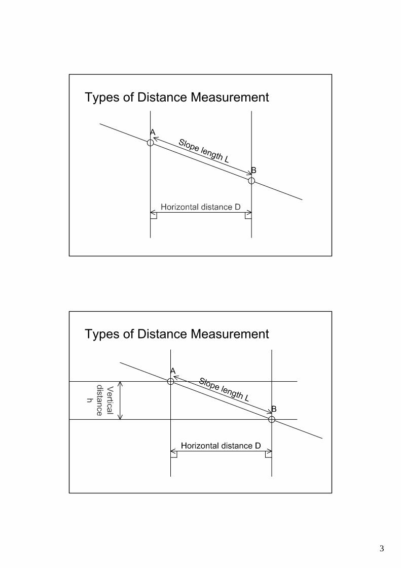
Types of Distance Measurement
Types of Distance Measurement
4
Examples: which one to use
1. If you are intending to draw a map or area, horizontal distance and height difference (vertical distance) should be used to enable plan and height information to be drawn.
2. If you are to locate points such as a corner of a building or centre line of a road, slope distance and vertical distance are required to enable pigs be located at correct points on site (Layinging Out).
Methods of Measurement
PacingAccuracy 1 : 100
TapingAccuracy 1 : 10,000
Electronic Distance Measurement (EDM)Accuracy 1 : 10,000 to 1:100,000
5
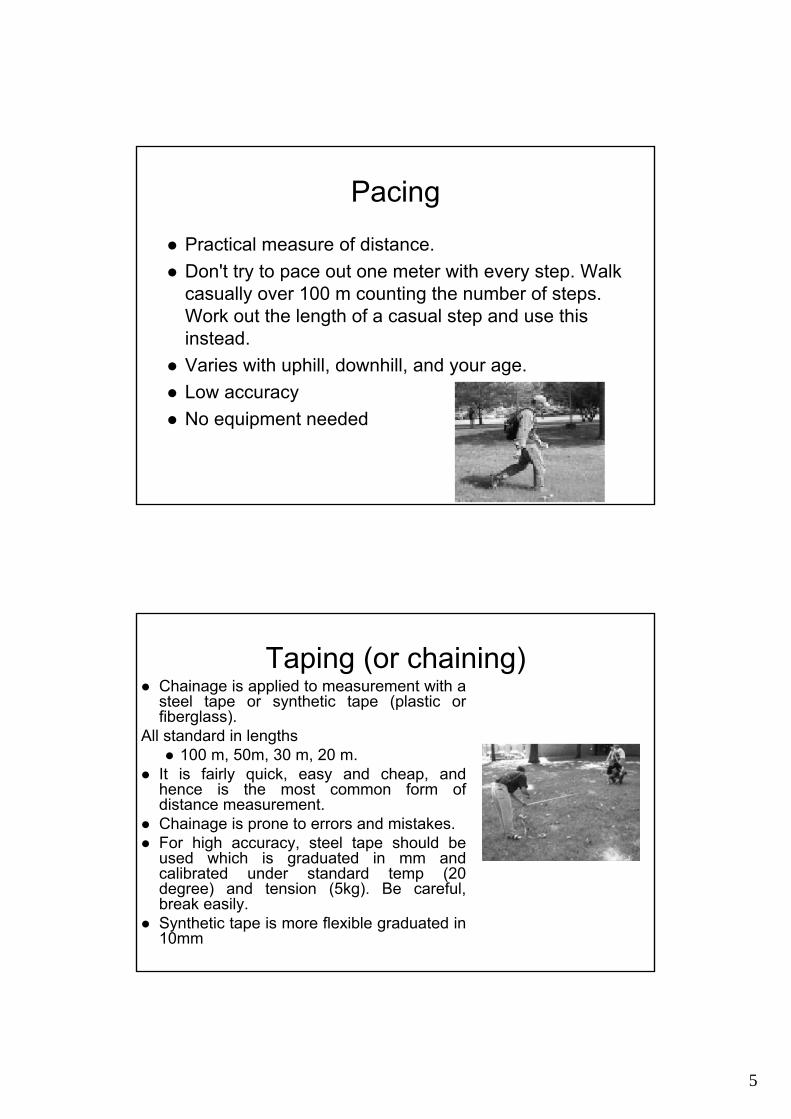
Pacing
Practical measure of distance.Don't try to pace out one meter with every step. Walk casually over 100 m counting the number of steps. Work out the length of a casual step and use this instead. Varies with uphill, downhill, and your age.Low accuracy No equipment needed
Taping (or chaining)Chainage is applied to measurement with a steel tape or synthetic tape (plastic or fiberglass).
All standard in lengths100 m, 50m, 30 m, 20 m.
It is fairly quick, easy and cheap, and hence is the most common form of distance measurement. Chainage is prone to errors and mistakes. For high accuracy, steel tape should be used which is graduated in mm and calibrated under standard temp (20 degree) and tension (5kg). Be careful, break easily.Synthetic tape is more flexible graduated in 10mm
6
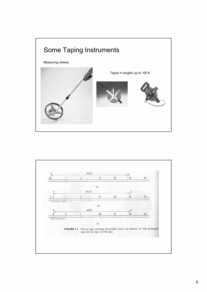
Measuring wheels
Tapes in lengths up to 100 ft
Some Taping Instruments
7
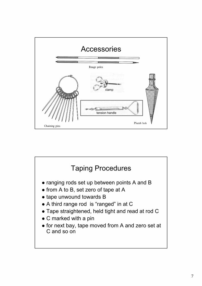
Accessories
clamp
tension handle
Taping Procedures
ranging rods set up between points A and Bfrom A to B, set zero of tape at Atape unwound towards BA third range rod is “ranged” in at CTape straightened, held tight and read at rod CC marked with a pinfor next bay, tape moved from A and zero set at C and so on

8
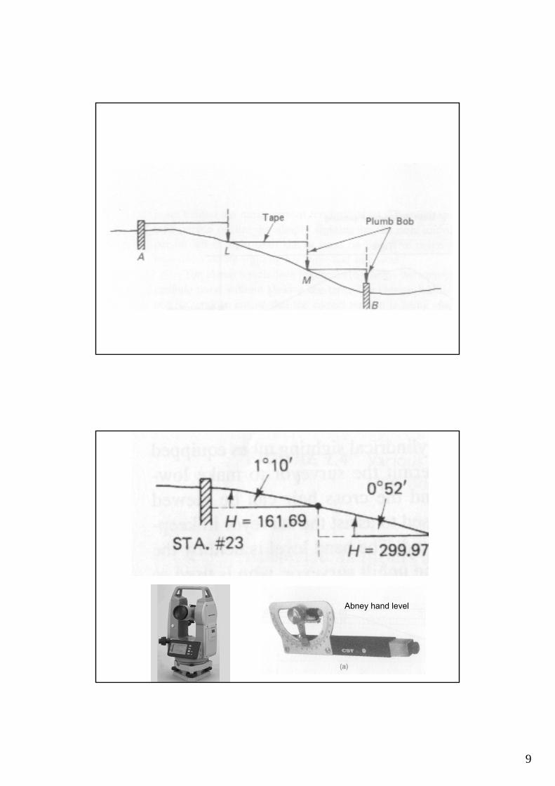
Length AB = 4 x Full tape distance + 1 Short section
REMEMBER ! It works only on smooth ground or uniform slope surfaces
9
Abney hand level

10
Slope-Hor. Dist. (H) / Slope dist. (S) = Cos θ
H = S Cos θ-Also H2 + V2 = S2 H = ( S2-V2) 1/2
-Slope = gradient (rate of grade) Ratios = V/H * 100 % = (tan θ) * 100 %
θ
SV
H
-Given: Slope distance. S and slope angle θH/S = Cos θ; then H = S . Cos θ
-Given: Slope distance. S and gradient (slope)Grad./100 = tan θ ; ........ Find θThen; H/S = Cos θ ; Find H
-Given: Slope distance S. And vertical. distance V.H = ( S2-V2) 1/2
θ
SV
H

11
Example
Example
How about this very uneven case
or if high accuracy is required?

12
Example
Sag curve
Sag curve measurement is not common nowadays and is restricted to steel tape only.
Taping: Corrections
Erroneous Tape LengthSlopeTensionTemperatureSag
Once a line is being measured, it is necessary to convert the measured length into a horizontal length. Series corrections have to be applied. Five possible corrections have to be considered. These are

13
Taping: Corrections
For synthetic tapes, only Erroneous Tape Length and slope corrections will be appliedThe best accuracy that can be achieved is in the order of 1:1000When using steel tapes, if only Erroneous Tape Length and slope corrections are considered, the best possible accuracy that can be obtained in the range 1:5000 If tension and temperature are added into consideration, accuracy can be increased to better than 1:10000 ~ 1: 20000Sag only applies if tape is supported only at ends
1. Erroneous Tape Lengthtape has a nominal length under certain conditions, a tape stretches with time.standardisation needs to be carried out frequently by using reference tape or baseline.
⎟⎟⎠
⎞⎜⎜⎝
⎛ −×=
n
nsmst L
LLLe
standardization length(actual tape length)
nominal length(assumed tape length)

14
For a 30m Nominal Length Tape
Used tape
For every 30m measurement, the small elongated amount should be added for correction.
When comparing to a standard tape, the used tape has a length
30 m + ∆l
2. Slope CorrectionAll plan distances are always quoted as horizontal distances L, therefore any distance not measured on the horizontal will need to be corrected for slope. Slope correction must ALWAYS be considered, and either eliminated in the field or mathematicallycompensated.
mL
θ
( )θcos1−= mslope LeAngle may be measured by Theodolites

15
3. Tension Correction
A tape has a given length when pulled with a certain tension. If the tension changes then so does the tape length.
( )AELTTe ms
tension ×−
=
Standardisation tension
Modulus of Elasticityof tape materialFor steel, E = 200,000 N/mm2
Cross sectionArea
Tension applied
Hook to the tape
Force applied

16
4. Temperature Correction
Most materials expand and contract with temperature change, and this effects taped distances. If a tape has stretched due to heat it will read shorter than it would at its normal (or standard) temperature.
)( tcLe mtemp Δ××=
Length error due toTemperaturechange
Measured length
Coefficient oflinear expansion
Temperaturechange

17
5. Sag Correction
If the tape cannot be supported for its length then it will hang freely under the influence of gravity. The shape of the tape will take is known as (sag) and can be determined mathematically.
2
232
24cosT
Lwe mcatenary ×
=θ
Tension applied to the ends
Angle of slopeWeight of tape per unit length
Combined Errors
tensionslopesagsttempma eeeeeLL ±−−±±=
Actual length is:
Steel Taping: Examples

18
A steel tape of nominal length 30 m was used to measurea line AB by suspending it between supports. The following measurements were recorded
Line Length Measured Slope Angle Mean Temp. TensionAB 29.872 m 3o 40’ 5oC 120 N
The standardisation length of the tape against a reference tape was known to be 30.014 m at 20oC and 50 N.
If the tape weighs 0.17 N/m and has a cross sectional area of 2 mm2, calculate the horizontal length of AB.
Temp. correction factor = 0.0000112 m/oC
( )( )m
o
0611.0043cos1872.29
cos-1L- correction slope m
−=
′−−=
= θ
( )
m
LLL
n
ns
0139.0000.30
000.30014.30872.29
L correction ationstandardis m
+=
−×=
−×=
( )( )
m
c
0050.02050000112.0872.29
tL correction etemperatur m
−=−××=
Δ×=
( ) ( )( )
m
TL
o
m
0022.012024
043cos872.2917.0
24cosw- correction sag
2
232
2
232
−=
′−=
=θ
horizontal length AB = 29.872 +(-0.0050+0.0139-0.0022-0.0611+0.0052)= 29.823m
( )
( )
m
EALm
0052.0210200872.2950120
T-T correctiontension
3
s
+=××
×−=
=
19
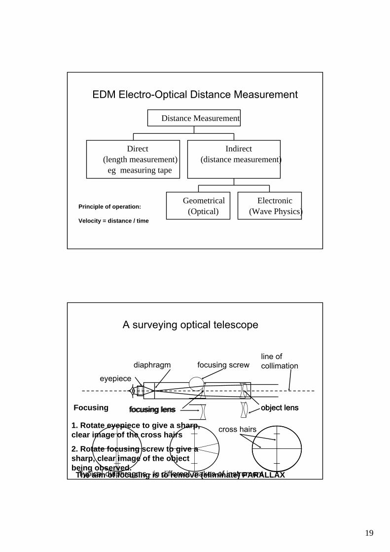
EDM Electro-Optical Distance Measurement
Principle of operation:
Velocity = distance / time
Direct(length measurement)
eg measuring tape
Geometrical(Optical)
Electronic(Wave Physics)
Indirect(distance measurement)
Distance Measurement
A surveying optical telescope
eyepiece
object lensobject lensfocusing lensfocusing lens
diaphragm
Typical diaphragms - in different makes of instrument
cross hairs
focusing screw
Focusing
1. Rotate eyepiece to give a sharp,clear image of the cross hairs
2. Rotate focusing screw to give asharp, clear image of the objectbeing observed.The aim of focusing is to remove (eliminate) PARALLAX
line of collimation
20
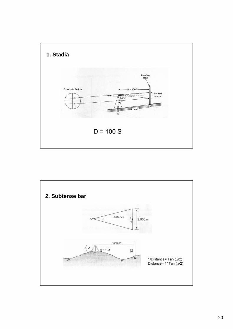
1. Stadia
D = 100 S
2. Subtense bar
1/Distance= Tan (α/2)Distance= 1/ Tan (α/2)
21
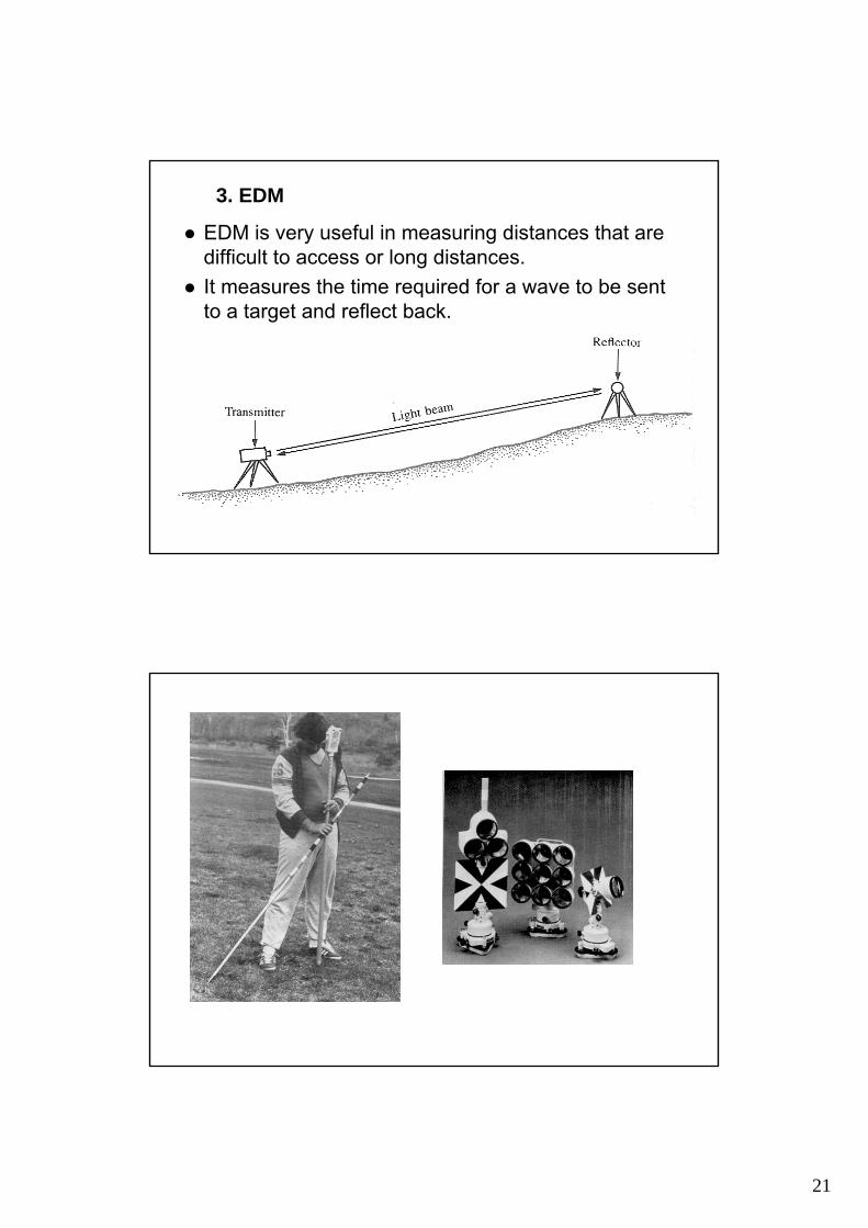
EDM is very useful in measuring distances that are difficult to access or long distances.It measures the time required for a wave to be sent to a target and reflect back.
3. EDM

22
2pnL +
=λ incomplete
fractional part of a cycle
L = (Velocity * time)/2
EDM Classifications
Described by form of electromagnetic energy.First instruments were primarily microwave (1947)Present instruments are some form of light, i.e. laser or near-infrared lights.
Described by range of operation.Generally microwave are 30 - 50 km range. (med)
Developed in the early 70’s, and were used for control surveys.
Light EDM’s generally 3 - 5 km range. (short) Used in engineering and construction
23
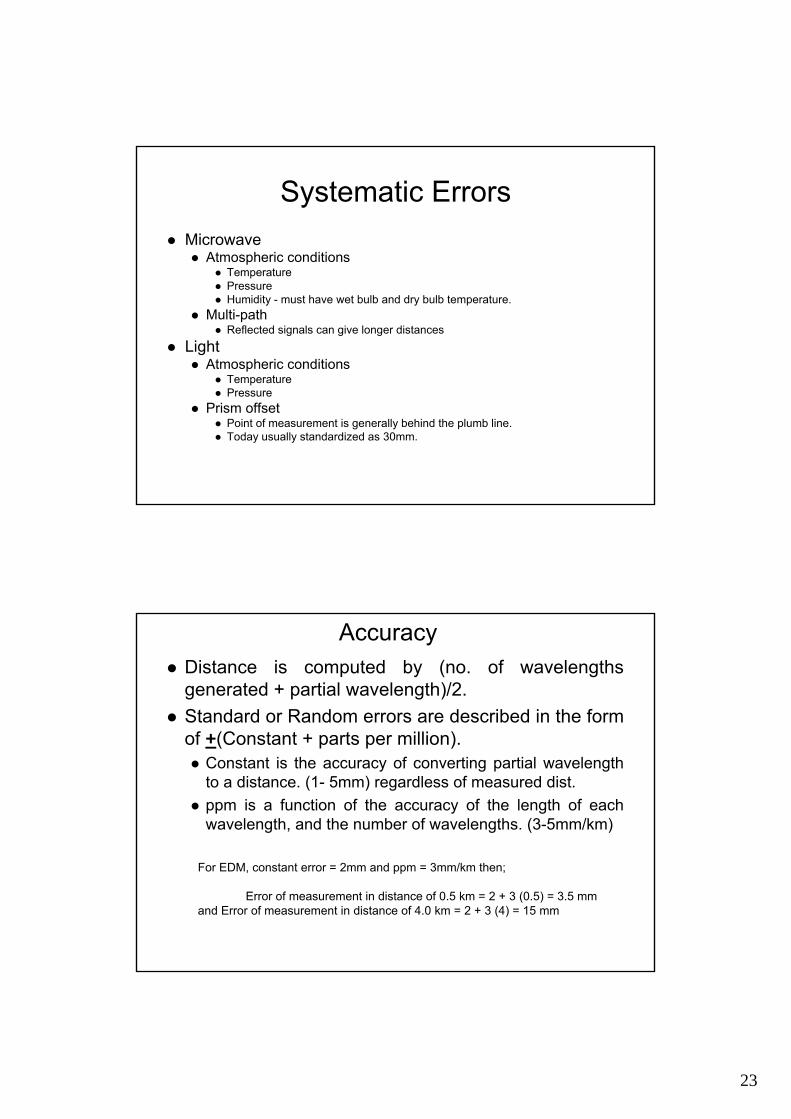
Systematic ErrorsMicrowave
Atmospheric conditions Temperature Pressure Humidity - must have wet bulb and dry bulb temperature.
Multi-path Reflected signals can give longer distances
Light Atmospheric conditions
Temperature Pressure
Prism offset Point of measurement is generally behind the plumb line. Today usually standardized as 30mm.
AccuracyDistance is computed by (no. of wavelengths generated + partial wavelength)/2. Standard or Random errors are described in the form of +(Constant + parts per million).
Constant is the accuracy of converting partial wavelength to a distance. (1- 5mm) regardless of measured dist.ppm is a function of the accuracy of the length of each wavelength, and the number of wavelengths. (3-5mm/km)
For EDM, constant error = 2mm and ppm = 3mm/km then;
Error of measurement in distance of 0.5 km = 2 + 3 (0.5) = 3.5 mmand Error of measurement in distance of 4.0 km = 2 + 3 (4) = 15 mm
24
The End
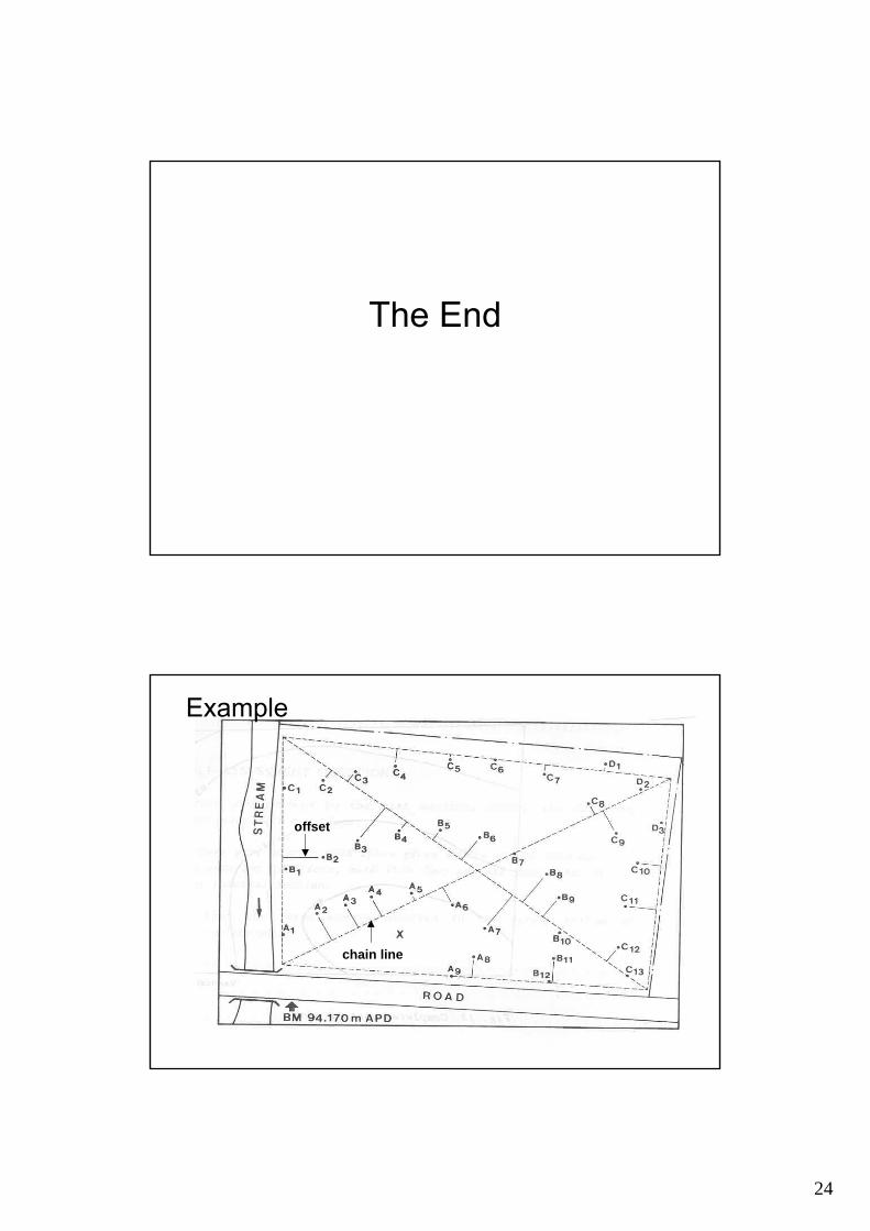
chain line
offset
Example
Top Related