


Languages
Pages
Legal

i
AUTOMATIC GREENHOUSE WATERING SYSTEM AND
MONITORING
MOHAMMAD IZHAN BIN JAFRY
A thesis submitted in fulfillment of the
requirements for the award of the degree of
Electrical Engineering (Electronics)
Faculty of Electrical & Electronics Engineering
Universiti Malaysia Pahang
November 2007

ii
I declare that this thesis entitled “AUTOMATIC GREENHOUSE WATERING
SYSTEM AND MONITORING” is the result of my own research except as cited in
the references. The thesis has not been accepted for any degree and is not
concurrently submitted in candidature of any other degree.
Signature : ____________________________
Author : MOHAMMAD IZHAN BIN JAFRY
Date : 17 NOVEMBER 2008

iii
Special dedication to my parents especially my mother that always inspire, love and stand beside me, my supervisor, my fellow colleagues, and all FKEE lecturers and staffs.
iv
ACKNOWLEDGEMENT
I would like to express my sincere thanks to my supervisor, Madam
Nurulfadzilah bte Hasan for her patience, guidance and advice throughout the year,
which proved valuable for the success of this thesis.
Also, I would like to thank my family, especially to my mother, Madam Jamilah
bte Uti for her encouragement and financial support through all this year.
I have to thank the helpful staffs of FKEE, for giving me the permission to do the
necessary research work and to use component needed. Furthermore thanks to Mr.
Mohammad Fadhil bin Abas for his help and advice.
Not forgetting also, my friends, heartfelt thanks to all of them for their support
and encouragement throughout the year. Their views and tips are useful indeed.
Unfortunately, it is not possible to list all of them in this limited space. Without their
continued support and interest, this thesis would not have been the same as presented here.
v
ABSTRACT
The primary issue of greenhouse based horticulture is to manage the greenhouse
environment optimally in order to comply with the economic and environmental
requirements. Pests and diseases, and extremes of heat and humidity, have to be
controlled, and irrigation is necessary to provide water. The solution to these problems is
by designing an automatic controlled system. Two sensors are used in this project. Soil
moisture sensor needed to automatically control the valve of watering system.
Temperature sensor will measure the condition of the greenhouse. Once the temperature
sensor detect that the environment temperature is higher than the predetermined
temperature value, the cooling fan will be in the on state and vice versa. Wireless
monitoring using RF are used in order to monitor the condition of the greenhouse in the
predetermine RF range. This project improved the irrigation system from manual to
automatic to make it easier to monitor the condition of the greenhouse remotely.
vi
ABSTRAK
Isu utama rumah hijau dalam pertanian adalah untuk mengurus keadaan rumah
hijau sepenuhnya dalam memenuhi keperluan ekonomi dan persekitaran. Serangga
perosak dan penyakit, suhu dan kelembapan yang keterlaluan hendaklan dikawal dan
sistem pengairan adalah diperlukan untuk membekalkan air. Untuk mengatasi masalah
ini adalah dengan mencipta satu system kawalan automatik. Dalam projek ini, dua
sensor digunakan. Sensor kelembapan tanah diperlukan untuk mengawal injap sistem
pengairan secara automatik. Sensor suhu akan meningkat keadaan suhu dalam rumah
hijau. Apabila sensor suhu mengesan keadaan sekeliling lebih tinggi daripada suhu yang
ditetapkan, kipas penyejuk akan dihidupkan atau sebaliknya. Pemantauan tanpa wayar
dengan RF digunakan untuk mengawasi keadaan rumah hijau dalam lingkungan
kawasan RF. Projek ini akan memperbaiki sistem pengairan daripada secara manual
kepada automatik untuk memudahkan pengguna mengawasi keadaan rumah hijau dari
jauh.
vii
TABLE OF CONTENTS
CHAPTER TITLE PAGE
TITLE PAGE i
DECLARATION ii
DEDICATION iii
ACKNOWLEDGEMENT iv
ABSTRACT v
ABSTRAK vi
TABLE OF CONTENTS vii
LIST OF TABLES x
LIST OF FIGURES xi
LIST OF ABBREVIATION xii
LIST OF APPENDICES xiii
1 INTRODUCTION
1.1 Background 1
1.2 Objectives 2
1.3 Scope 2
1.4 Problem Statement 3
1.5 Methodology 4
1.5 Thesis Outline 6
viii
2 LITERATURE REVIEW
2.1 Greenhouse 7
2.1 Microcontroller 8
2.2 Sensors 8
2.3 Wireless Data Communicator 10
2.4 Valve 11
2.5 Graphical User Interface GUI 12
3 STSTEM DESIGN
3.1 Introduction 13
3.2 Hardware development 14
3.3 Microcontroller MC68HC11 Board 15
3.4 Temperature Sensor 17
3.5 Soil Moisture Sensor 20
3.6 Relay 22
3.7 Irrigation Valve 23
3.8 Transmitter and Receiver 24
3.9 Four Bit Data Transmitter/Receiver 27
3.10 WP11 29
3.11 THRSim 11 Software 30
3.12 MAX 232 34
4 RESULTS
4.1 Microcontroller (MC68HC11A1) 36
4.2 Hardware 38
4.3 Software 42
5 CONCLUSION & RECOMMENDATIONS
5.1 Conclusion 47
5.2 Recommendations 49
5.3 Costing and Recommendation 50

ix
REFERENCES 52
APPENDICES 54
APPENDIX A1 55
APPENDIX A2 56
APPENDIX A3 57
APPENDIX B1 58
APPENDIX B2 65
APPENDIX B3 70
APPENDIX B4 74
APPENDIX B5 80
APPENDIX B6 86
x
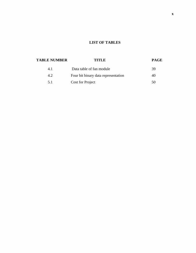
LIST OF TABLES
TABLE NUMBER TITLE PAGE
4.1 Data table of fan module 39
4.2 Four bit binary data representation 40
5.1 Cost for Project 50

xi
LIST OF FIGURES
FIGURE NUMBER TITLE PAGE
3.1 Block Diagram of the System 14
3.2 Microcontroller pin connection 16
3.3 Basic Centigrade Temperature Sensor 17
3.4 Connection Diagram LM35DZ 18
3.5 Flowchart of Initializing ADC 19
3.6 Soil moisture sensor circuit 21
3.7 Development of Soil moisture sensor 21
3.8 Relay Connection 22
3.9 Irrigation Valve 23
3.10 Actual irrigation valve 26
3.11 Connection of transmission circuit 27
3.12 Connection of receiver circuit 26
3.13 Actual Transmitter and receiver module 26
3.14 Four bit transmitter/receiver circuit 27
3.15 Four bit transmitter on breadboard 28
3.16 Four bit receiver on breadboard 29
3.17 WP11 Software 30
3.18 THRSim11 Software simulator 32
3.19 EIA232 interface 34
4.1 Output waveform at pin 27 36
4.2 Output system hardware 38
4.3 Full design GUI application 41
4.4 GUI application system 42
4.5 Transmitter circuit board 44
4.6 Receiver circuit board 45

xii
LIST OF ABBREVIATION
RF Radio Frequency
ADC Analog Digital Converter
AC Alternating Current
DC Direct Current
GUI Graphical User Interface
ADPU Analog to digital power unit
CSEL Clock select
xiii
LIST OF APPENDICES
APPENDIX TITLE PAGE
A1 MC68HC11 Memory map
A2 Transmitter full circuit design
A3 Receiver full circuit design
B1 Datasheet of MAX233
B2 Datasheet of LM35DZ
B3 Datasheet of Diode 1N4004
B4 Datasheet of HT12D
B5 Datasheet of HT12E
B6 Datasheet of Transistor QN2222
1
CHAPTER 1
INTRODUCTION
1.1 Background
A Greenhouse is a building with glass walls and roof; for the cultivation and
exhibition of plants under controlled conditions. Greenhouses also are often used for
growing flowers, vegetables, fruits, and tobacco plants. Pests and diseases, and
extremes of heat and humidity, have to be controlled, and irrigation is necessary to
provide water. Greenhouses protect crops from too much heat or cold, shield plants
from dust storms and blizzards, and help to keep out pests. Light and temperature
control allows greenhouses to become suitable place for growing plants. In other word,
a greenhouse is a structure that provides protection and a controlled environment for
raising plan indoors. The primary issue of greenhouse based horticulture is to manage
the greenhouse environment optimally in order to comply with the economic and
environmental requirements.
2
1.2 Objectives
The objective of this project is to implement automatic greenhouse watering
system based on soil moisture sensor and wireless based system monitoring.
1.3 Scope
Several scopes that need to be considered in this project:
i. Sensor used to control the watering system is soil moisture sensor.
ii. Fan system control based on temperature sensor is used as greenhouse
temperature controller.
iii. The condition of the Sensors & outputs are to be monitor with remote
display based on wireless module.

3
1.4 Problem Statement
Irrigation is the important thing on a greenhouse system. The water we provide,
which is the main element, will make sure the plants survive on certain circumstances.
As we all know, most of the gardener use the manual system to irrigate their plant but
this system is not efficient. The plants will either die if there is not enough water supply
to the plant or vice versa. Plus the gardener must often monitor their greenhouse to
ensure the conditions of their plant are in the good health.
In order to maintain the condition and overcome the problem, the automatic
watering system and remote monitoring is used. This will reduce the time if using
automatic rather than manual way of watering. Fewer workers are needed to maintain
the plants or crops. The sensors such as temperature sensor and soil moisture detector are
used to control the temperature and watering in the greenhouse.
The system also has the capacity to monitor the condition of greenhouse
remotely from computer by using wireless module. The information will be transmitted
by using radio frequency and the data will display using third party software such as
visual basic. So user will know the condition of their greenhouse without going to the
site and get the information.

4
1.5 Methodology
In order to achieve the objective of the scope few tasks need to be done for the
hardware of the system and the GUI application software. For the hardware of the
system there are four parts which have to be considered. They are the microcontroller
board, the transmitter circuit and the receiver circuit. First of all, in this system, both of
the microcontrollers have to be test and check for it functionality. It is to make sure that
the microcontroller later can be initialized and the proper program can be burn into its
EEPROM to do the appropriate task.
Secondly, transmitter and the receiver module need to be test for its functionality.
It can be done by sending a bit of data from the transmitter to the receiver. The push
button and the LED can be used as the representation of data sending and receiving.
After that, the circuit can be integrating with both microcontroller and then the
connection can be done.
Finally, the MAX233 is needed to test for its functionality. It is to make sure that
the data can be serially send and receive through MAX233 to the microcontroller of the
system. It can be made by downloading program of assembly language into the
EEPROM of the microcontroller.
For the software of the system, there are two parts which have to be considered.
They are the assembly language programming and the Visual Basic programming for
GUI application. For the assembly language, the coding needed to be testing on the
THRSim simulator software. The purpose of this simulator program is to debug errors.
The Visual Basic 6 software used to make a connection to the remote monitoring using
5
GUI application. Hyper terminal is used to record data that have been received through
the serial connection.
The last part in order to achieve the objective is to test the output of the system.
The driver circuits which consist of relay and transistor are needed to be tested so that
the cooling fan and the irrigation valve are functional. To test the relay is by giving
appropriate power supply to its coil.

6
1.6 Thesis Outline
Chapter 1 discuss on the background of the project, objectives, scope of the
project, problem statement, methodology and also the thesis outline.
Chapter 2 focuses on literature reviews of this project based on journals and other
references.
Chapter 3 mainly discuss on the system design of the project. Details on the
progress of the project are explained in this chapter.
Chapter 4 presents the results of the project. The discussion focused on the result
based on the experiment.
Chapter 5 concludes overall about the project. Future recommendations and
commercialization are also discussed in this chapter.

7
CHAPTER 2
LITERTURE REVIEW
2.0 Greenhouse
The development of models and strategies to control the environment of
greenhouse crops started with the shoot environment, that is, with the greenhouse
climate. One important reason was that influencing variables such as temperature,
humidity, irradiation or CO2 concentration are easier to measure and to control.
[1Hans Peter Klaring, 2000]
From this research, we can see that there are a few factors that need to be control in a
greenhouse. Those factors that need to be considered are temperature, humidity, irradiation
or carbon dioxide concentration. But, in this project, factors that are going to be considered
are only the temperature and soil humidity in a greenhouse.

8
2.1 Microcontroller
A microcontroller is a computer-on-a-chip. It is a type of microprocessor
emphasizing high integration, low power consumption, self-sufficiency and cost-
effectiveness, in contrast to a general-purpose microprocessor.
Microcontrollers are frequently used in automatically controlled products and
devices, such as automobile engine control systems, remote controls, office machines,
appliances, power tools, and toys.
[From Wikipedia]
By reducing the size, cost, and power consumption compared to a design using a
separate microprocessor, memory, and input/output devices, microcontrollers make it
economical to electronically control many more processes.
2.2 Sensors
A sensor is a device which measures a physical quantity and converts it into a
signal which can be read by an observer or by an instrument.
[From Wikipedia]

9
Because sensors are a type of transducer, they change one form of energy into
another. For this reason, sensors can be classified according to the type of energy
transfer that they detect. Soil moisture measurements provide useful information for
agriculture, such as grape growers, soil stability monitoring, dam monitoring and
construction activities.
[R. Frank, 2000]
A typical greenhouse contains several sensors form measuring humidity,
temperature, pressure, carbon dioxide, light, motion, etc, and contains several actors,
such as, air conditioners, floodlights, sprinkler and water management facility, plant
decks, air blowers, fans, CO2 production units, etc. In this project will only consider the
temperature and the soil moisture of the greenhouse. There are many types of soil
moisture sensor such as tensiometer, resistance block capacitive and etc. every types
have their own characteristics and system operation.
2.2.1 Gypsum Blocks soil moisture sensor
Gypsum blocks are one of the lowest cost soil moisture monitoring products
available. Their low cost and ease of interpretation makes them ideal for seasonal crops
A block of gypsum placed in the soil will wet up and dry out at close to the rate of soil.
When gypsum is wet it conducts electricity easily (it is low resistance), and when dry is
a poor conductor (high resistance). A pair of electrodes within the block measures this
change in resistance and a once off calibration equates it to soil moisture tension. It is
possible to measure the resistance of the soil directly using a pair of electrodes, but the
measurement would also be influenced by changes in the soil conductivity brought about
by the presence of salt and other materials. The gypsum ions provides a buffer against
10
the impact of salt and nutrients – effectively preventing the salt ions from reaching the
electrodes – and ensuring the sensor is only responding to moisture levels.
2.2.2 Temperature sensor LM35
The LM35 series are precision integrated-circuit temperature sensors, whose
output voltage is linearly proportional to the Celsius (Centigrade) temperature.
[National Semiconductor]
2.3 Wireless Data Communication
Wireless sensor data monitoring is much less labor intensive than periodic
sampling by workers for most applications. Updates need be done only infrequently (e.g.
daily), and only with moderate accuracy, but monitoring is often needed over a wide
area and for long periods.
[Darold C. Wobschall]
This project consist transmitter and receiver to transfer data in order to monitor
the greenhouse remotely. Both module are connected to the encoder and decoder also
microcontroller. Radio is the wireless transmission of signals, by modulation of
electromagnetic waves with frequencies below those of visible light. Electromagnetic
radiation travels by means of oscillating electromagnetic fields that pass through the air

11
and the vacuum of space. It does not require a medium of transport. Information is
carried by systematically changing (modulating) some property of the radiated waves,
such as their amplitude or their frequency. When radio waves pass an electrical
conductor, the oscillating fields induce an alternating current in the conductor. This can
be detected and transformed into sound or other signals that carry information.
2.4 Valve
Solenoid valves are electromechanical valves that are controlled by stopping or
running an electrical current through a solenoid, in order to change the state of the valve.
A solenoid is a coil of wire that is magnetized when electricity runs through it. The
solenoid valve makes use of this solenoid in order to activate a valve, thus controlling
water flow, airflow and other things with electricity.
[Jimmy Sturo, 2006]
There are many applications using valve especially for the electrical devices. By
using electromagnetic, valve is automatically energize and doing its job according to the
application system. The function is as replacing the conversional valve, which does need
user to operate the system. It is lot easier and more reliable.
12
2.5 Graphical User Interface GUI
A graphical user interface (GUI) is a type of user interface which allows people
to interact with electronic devices like computers, hand-held devices (MP3 Players,
Portable Media Players, Gaming devices), household appliances and office equipment. A
GUI offers graphical icons, and visual indicators as opposed to text-based interfaces,
typed command labels or text navigation to fully represent the information and actions
available to a user. The actions are usually performed through direct manipulation of the
graphical elements.
[Wikipedia]
By using GUI application it is more useful and user friendly. With interpretation
of graphical technique it is easy to understand and lot more easily to control and
manipulate the interface.
Top Related