


Languages
Pages
Legal

About the Presentations
• The presentations cover the objectives found in the
opening of each chapter.
• All chapter objectives are listed in the beginning of
each presentation.
• You may customize the presentations to fit your
class needs.
• Some figures from the chapters are included. A
complete set of images from the book can be found
on the Instructor Resources disc.
A+ Guide to Hardware:
Managing, Maintaining, and
Troubleshooting, 5e
Chapter 1
Introducing Hardware
A+ Guide to Hardware
Objectives
• Learn that a computer requires both hardware and
software to work
• Learn about the many different hardware
components inside of and connected to a computer
3
A+ Guide to Hardware
Hardware Needs Software to Work
• Hardware
– Computer’s physical components
• Monitor, keyboard, memory, hard drive
• Software
– Instruction set
• Directs hardware to accomplish a task
– Uses hardware for four basic functions
• Input, processing, storage, output
• Hardware components
– Require an electrical system
4

A+ Guide to Hardware
Figure 1-1 Computer activity consists of input, processing, storage,
and output
Courtesy: Course Technology/Cengage Learning
5
A+ Guide to Hardware
Hardware Needs Software to Work
(cont’d.)
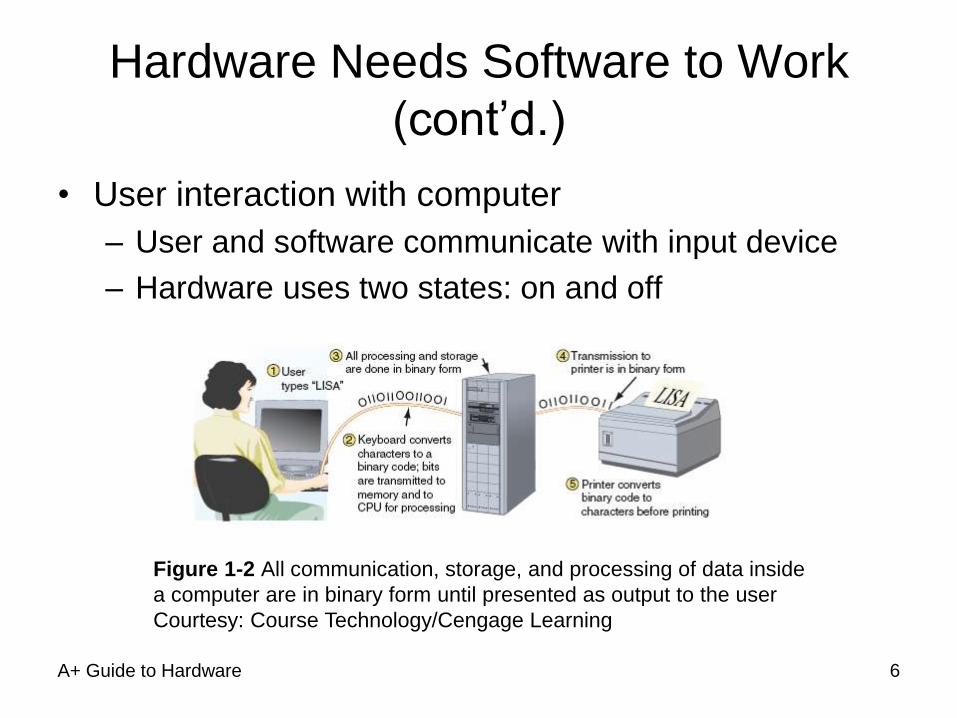
• User interaction with computer
– User and software communicate with input device
– Hardware uses two states: on and off
Figure 1-2 All communication, storage, and processing of data inside
a computer are in binary form until presented as output to the user
Courtesy: Course Technology/Cengage Learning
6
Hardware Needs Software to Work
(cont’d.)
• Binary number system
– Stores and reads two states
• Zero or one
– Bit: binary digit
• Value of zero or one
– Nibble: four bits
– Byte: eight bits
– Used for counting, calculation, storage operations
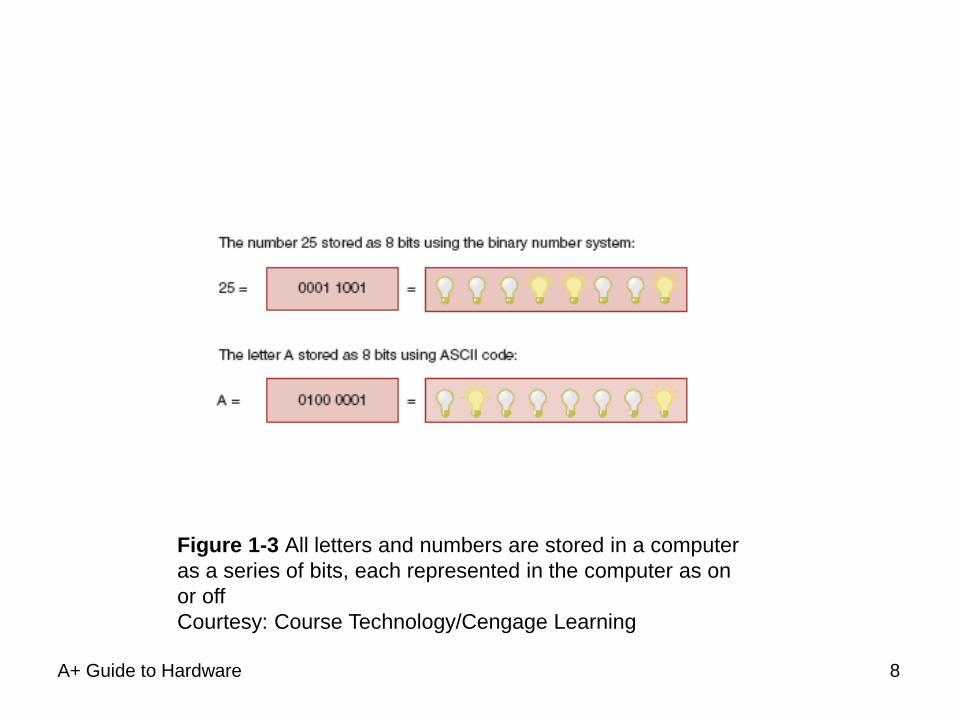
• American Standard Code for Information
Interchange (ASCII)
– Used for storing information A+ Guide to Hardware 7
A+ Guide to Hardware
Figure 1-3 All letters and numbers are stored in a computer
as a series of bits, each represented in the computer as on
or off
Courtesy: Course Technology/Cengage Learning
8
A+ Guide to Hardware
PC Hardware Components
• Input/output (I/O) devices: external to the case
• Processing, storage devices: internal to the case
• Central processing unit (CPU)
– Also called: processor, microprocessor
– Reads input, processes data, writes data to storage
• Elements required by I/O, storage devices
– Method for CPU to communicate with the device
– Software to instruct, control the device
– Electricity to power the device
9
A+ Guide to Hardware
Hardware Used for Input and Output
• I/O device communication with computer components
– Wireless
– Cabled using a port
• Access point located in back or front of case
• Primary input devices
– Keyboard, mouse
• Requires electricity from inside case
• Primary output devices
– Monitor: visually displays primary computer output
– Printer: produces paper output (hard copy)
10
A+ Guide to Hardware
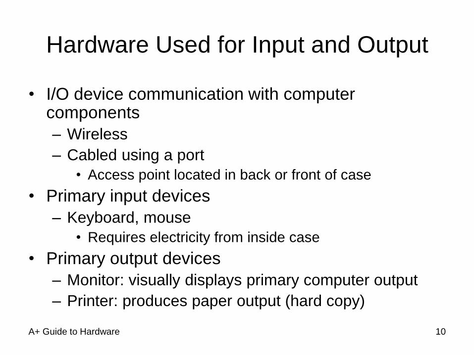
Figure 1-4 Input/output devices connect to the computer case by
ports usually found on the back of the case
Courtesy: Course Technology/Cengage Learning
11
A+ Guide to Hardware
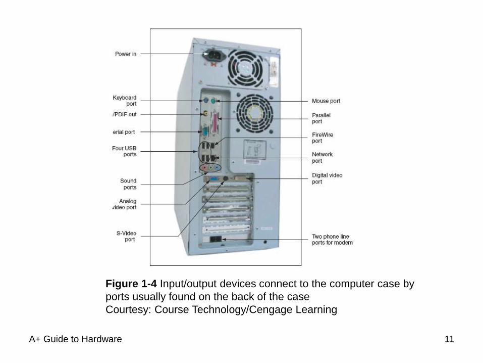
Figure 1-5 The keyboard and the
mouse are the two most popular
input devices
Courtesy: Course
Technology/Cengage Learning
Figure 1-6 The two most popular output
devices are the monitor and the printer
Courtesy: Course Technology/Cengage
Learning
12
A+ Guide to Hardware
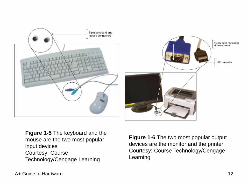
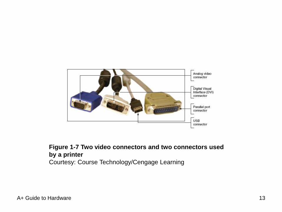
Figure 1-7 Two video connectors and two connectors used
by a printer
Courtesy: Course Technology/Cengage Learning
13
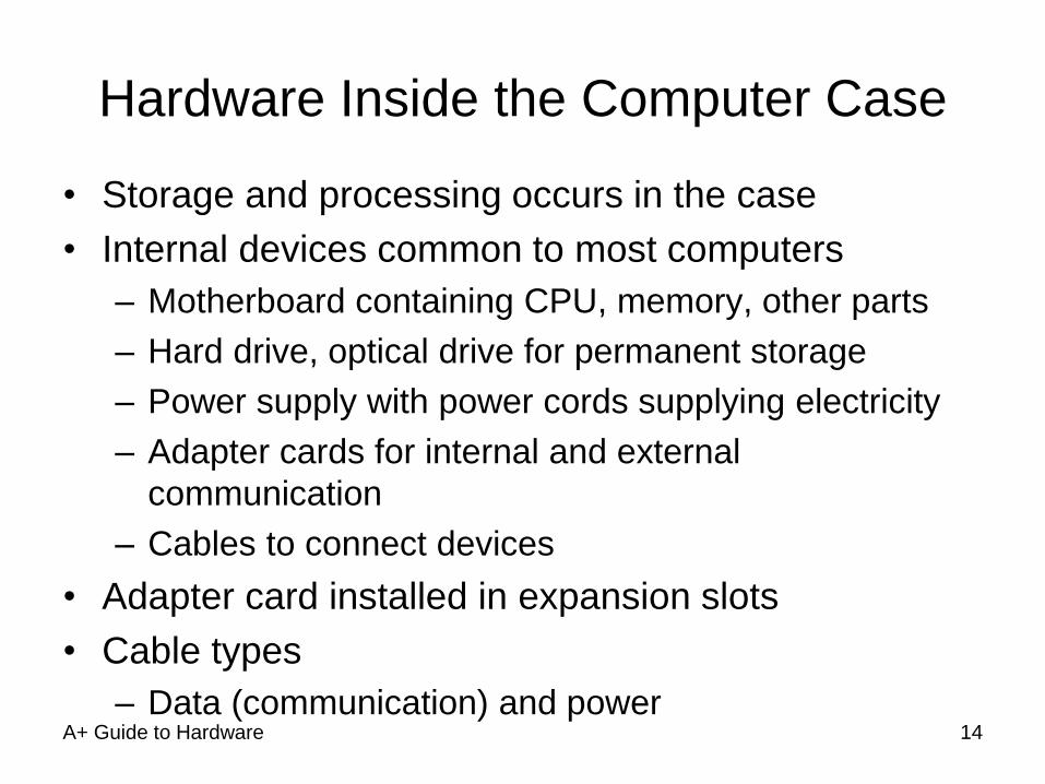
Hardware Inside the Computer Case
• Storage and processing occurs in the case
• Internal devices common to most computers
– Motherboard containing CPU, memory, other parts
– Hard drive, optical drive for permanent storage
– Power supply with power cords supplying electricity
– Adapter cards for internal and external
communication
– Cables to connect devices
• Adapter card installed in expansion slots
• Cable types
– Data (communication) and power A+ Guide to Hardware 14
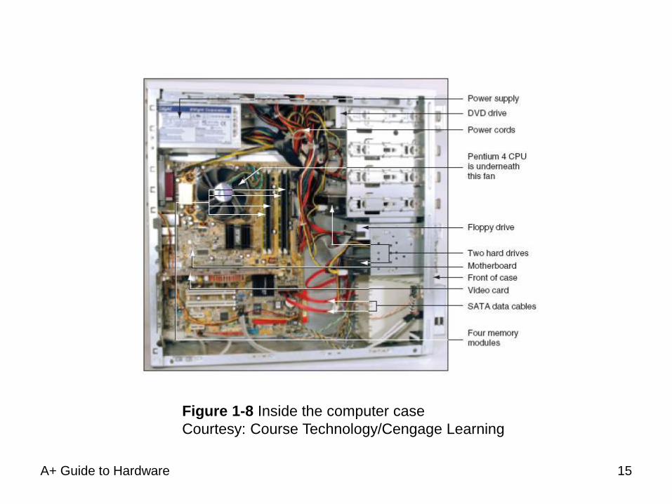
A+ Guide to Hardware
Figure 1-8 Inside the computer case
Courtesy: Course Technology/Cengage Learning
15
A+ Guide to Hardware
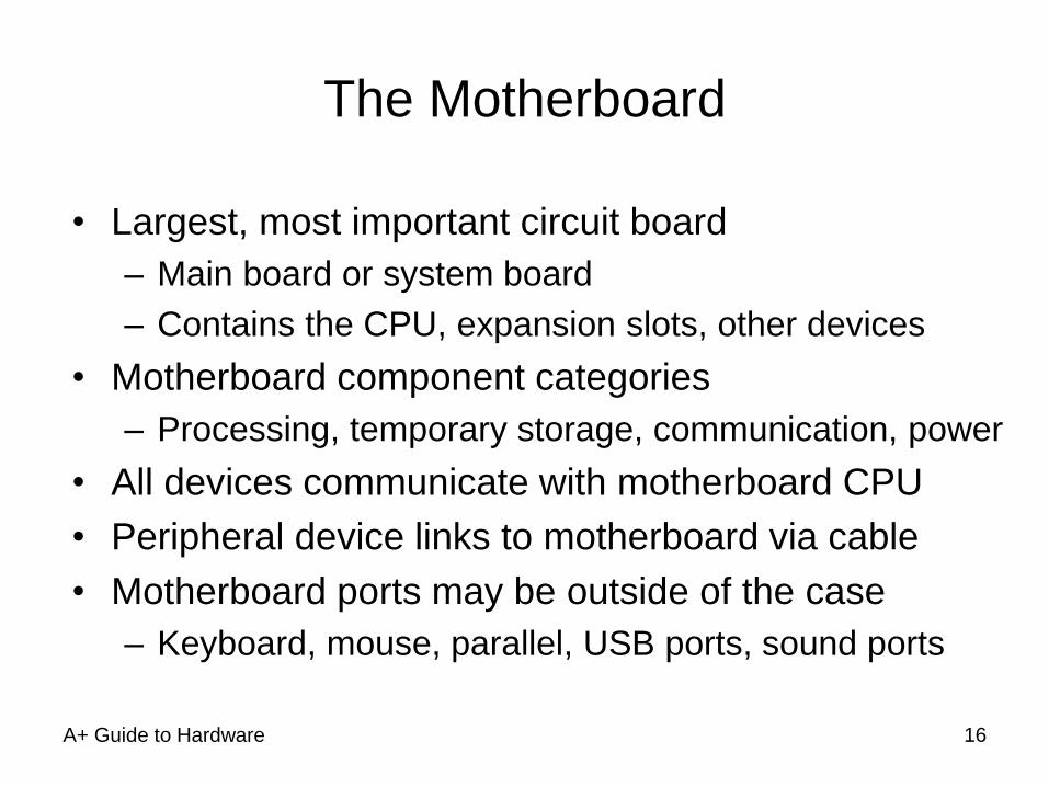
The Motherboard
• Largest, most important circuit board
– Main board or system board
– Contains the CPU, expansion slots, other devices
• Motherboard component categories
– Processing, temporary storage, communication, power
• All devices communicate with motherboard CPU
• Peripheral device links to motherboard via cable
• Motherboard ports may be outside of the case
– Keyboard, mouse, parallel, USB ports, sound ports
16
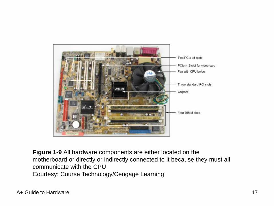
A+ Guide to Hardware
Figure 1-9 All hardware components are either located on the
motherboard or directly or indirectly connected to it because they must all
communicate with the CPU
Courtesy: Course Technology/Cengage Learning
17
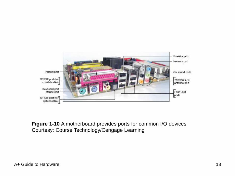
A+ Guide to Hardware
Figure 1-10 A motherboard provides ports for common I/O devices
Courtesy: Course Technology/Cengage Learning
18
The Processor and the Chipset
• CPU
– Chip inside the computer
– Performs most data processing
• Chipset
– Group of microchips controlling data flow
• Personal computer (PC)
– Focus of this text
• Major CPU, chipsets manufacturers
– Intel Corporation, AMD
A+ Guide to Hardware 19
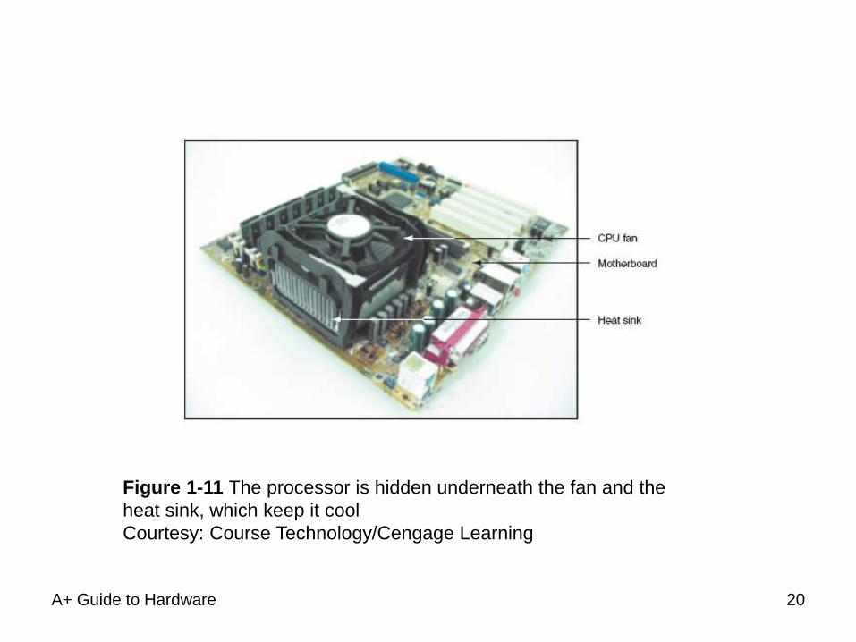
A+ Guide to Hardware
Figure 1-11 The processor is hidden underneath the fan and the
heat sink, which keep it cool
Courtesy: Course Technology/Cengage Learning
20
A+ Guide to Hardware
Storage Devices
• Primary storage (main memory)
– Temporary storage used by the processor
• Secondary storage (permanent storage)
– Enables data to persist after machine turned off
– Examples: hard drive, CD, DVD, USB drive
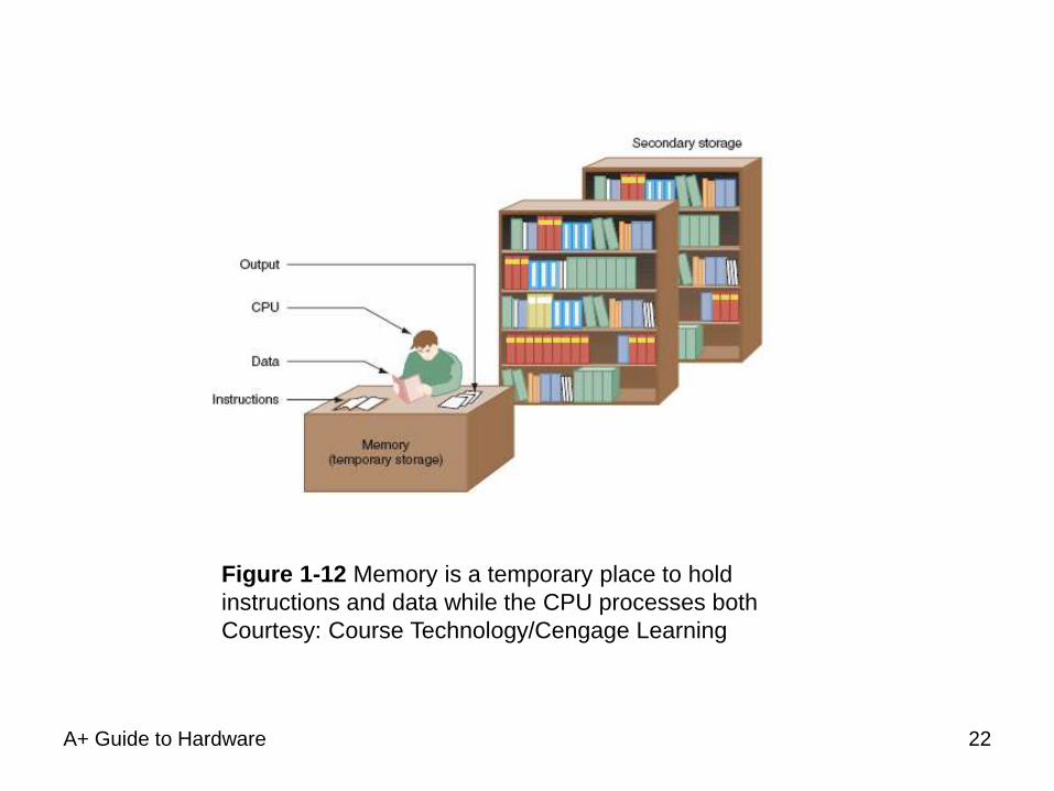
• Primary-secondary memory relationship analogy
– Library book stacks: permanent storage
– Books moved to a desk: temporary storage
21
A+ Guide to Hardware
Figure 1-12 Memory is a temporary place to hold
instructions and data while the CPU processes both
Courtesy: Course Technology/Cengage Learning
22
A+ Guide to Hardware
Primary Storage
• Provided by random access memory (RAM)
– Located on motherboard, adapter cards
• RAM chips
– Embedded on small board
– Plugs into motherboard
– Most common: dual inline memory module (DIMM)
– Video memory: embedded on video card
• Volatile memory
• Non-volatile memory
23
A+ Guide to Hardware
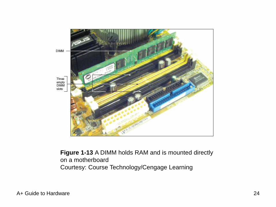
Figure 1-13 A DIMM holds RAM and is mounted directly
on a motherboard
Courtesy: Course Technology/Cengage Learning
24
A+ Guide to Hardware
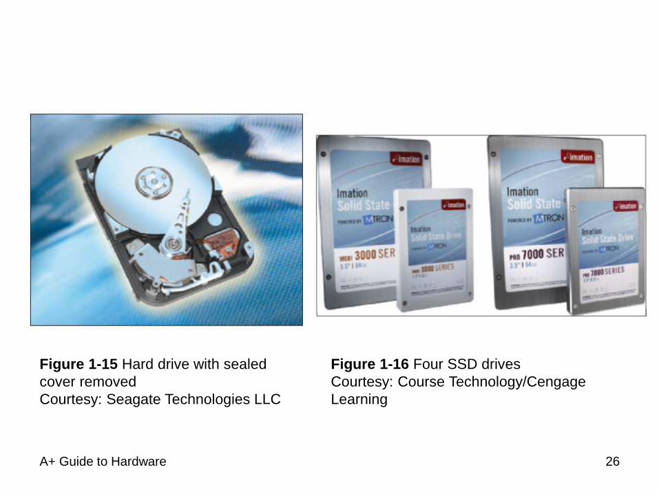
Secondary Storage
• Remote storage locations containing data and
instructions
– Cannot be directly processed by CPU
– Permanent
• Hard drives
– Main secondary computer storage device
– Magnetic hard drives
• Use Integrated Drive Electronics (IDE)
– Solid state drive (SSD)
• Use nonvolatile flash memory
25
A+ Guide to Hardware
Figure 1-15 Hard drive with sealed
cover removed
Courtesy: Seagate Technologies LLC
Figure 1-16 Four SSD drives
Courtesy: Course Technology/Cengage
Learning
26
A+ Guide to Hardware
Secondary Storage (cont’d.)
• Hard drives (cont’d.)
– ATA (AT Attachment) standard
• Specifies motherboard-hard drive interface
• Types: serial ATA (SATA), parallel ATA (PATA)
– Serial ATA standard
• External SATA (eSATA)
• Usually two to eight SATA and eSATA connectors
– Parallel ATA (PATA)
• Slower than SATA
• Two connectors on a motherboard for two data cables
• Accommodates up to four IDE devices
27
A+ Guide to Hardware
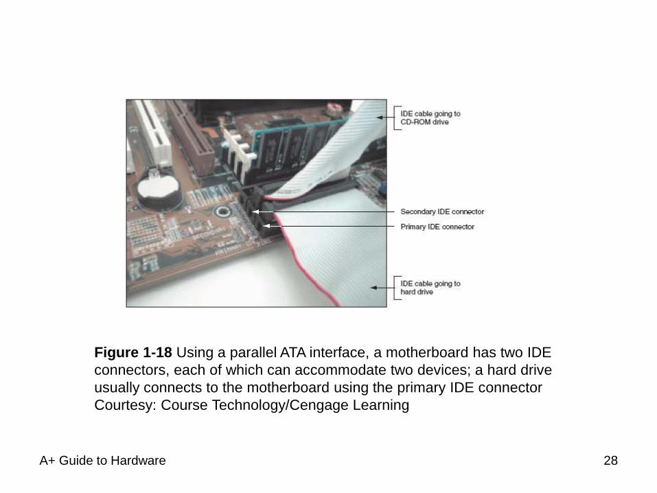
Figure 1-18 Using a parallel ATA interface, a motherboard has two IDE
connectors, each of which can accommodate two devices; a hard drive
usually connects to the motherboard using the primary IDE connector
Courtesy: Course Technology/Cengage Learning
28
A+ Guide to Hardware
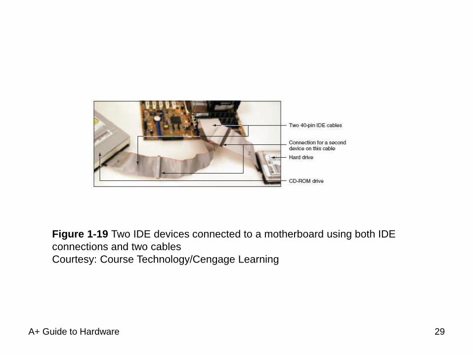
Figure 1-19 Two IDE devices connected to a motherboard using both IDE
connections and two cables
Courtesy: Course Technology/Cengage Learning
29
A+ Guide to Hardware
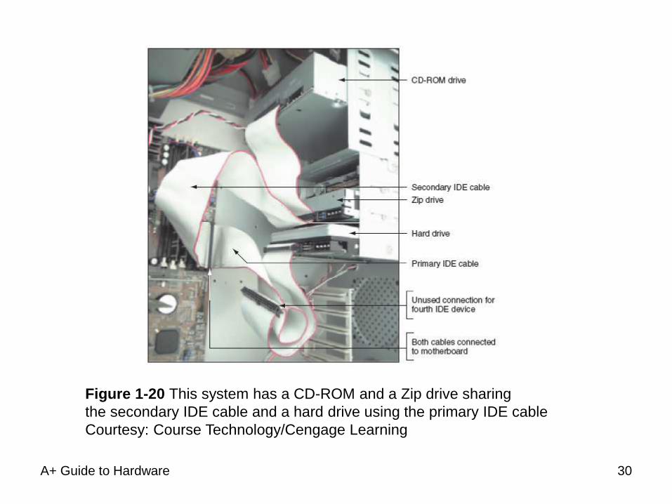
Figure 1-20 This system has a CD-ROM and a Zip drive sharing
the secondary IDE cable and a hard drive using the primary IDE cable
Courtesy: Course Technology/Cengage Learning
30
A+ Guide to Hardware
Secondary Storage (cont’d.)
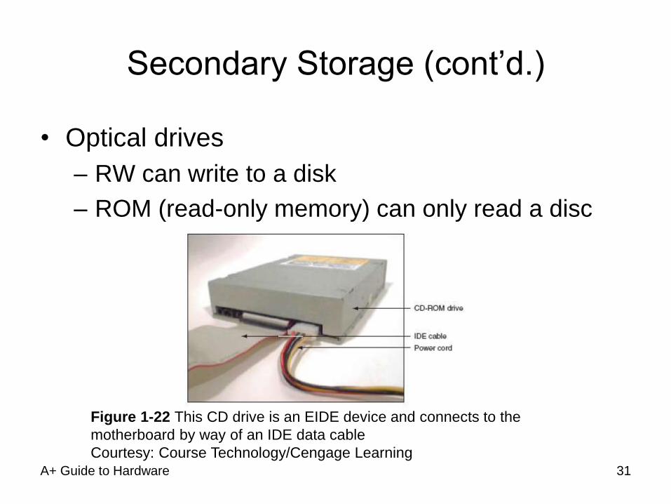
• Optical drives
– RW can write to a disk
– ROM (read-only memory) can only read a disc
Figure 1-22 This CD drive is an EIDE device and connects to the
motherboard by way of an IDE data cable
Courtesy: Course Technology/Cengage Learning 31
Secondary Storage (cont’d.)
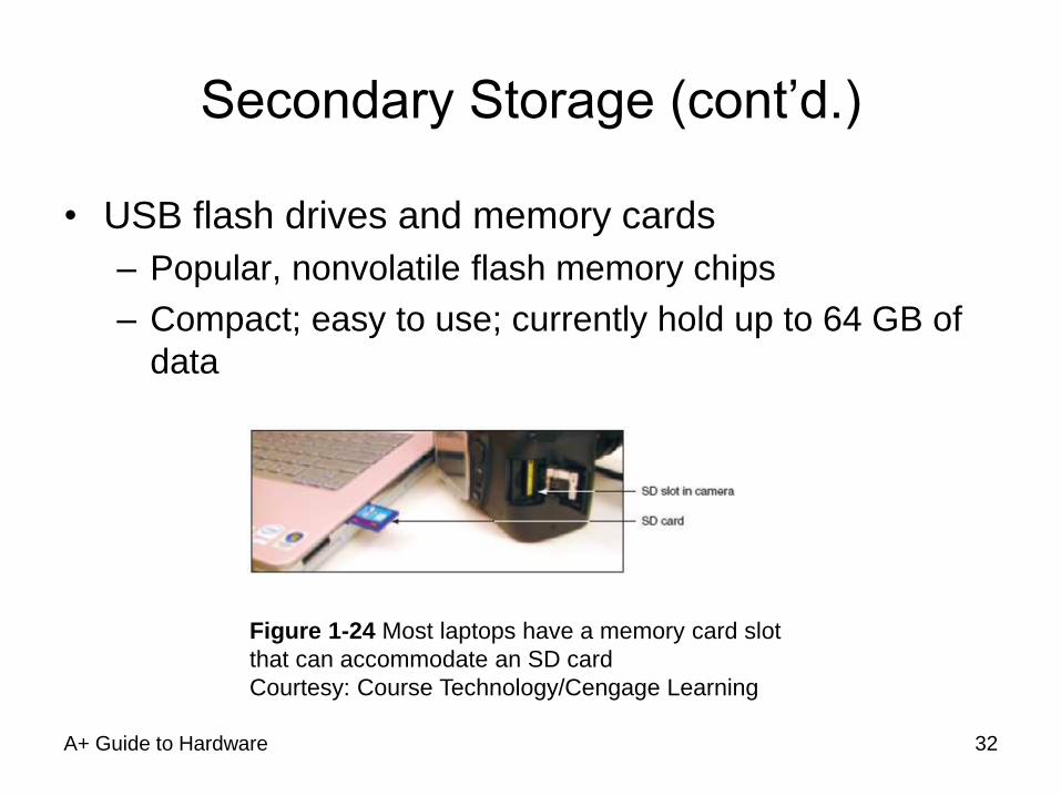
• USB flash drives and memory cards
– Popular, nonvolatile flash memory chips
– Compact; easy to use; currently hold up to 64 GB of
data
A+ Guide to Hardware
Figure 1-24 Most laptops have a memory card slot
that can accommodate an SD card
Courtesy: Course Technology/Cengage Learning
32
A+ Guide to Hardware
Secondary Storage (cont’d.)
• Floppy drive
– Older secondary storage device
– 3.5-inch disk holding 1.44 MB of data
– Floppy drive connector
• Distinct from IDE connectors
• Floppy drive cable accommodates one or two drives
33
A+ Guide to Hardware
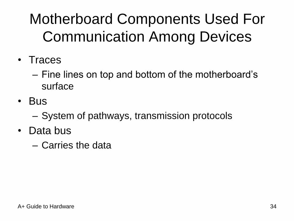
Motherboard Components Used For
Communication Among Devices
• Traces
– Fine lines on top and bottom of the motherboard’s
surface
• Bus
– System of pathways, transmission protocols
• Data bus
– Carries the data
34
A+ Guide to Hardware
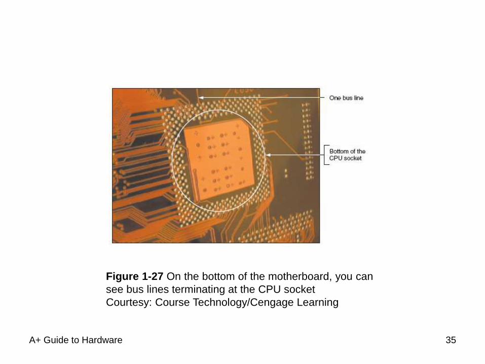
Figure 1-27 On the bottom of the motherboard, you can
see bus lines terminating at the CPU socket
Courtesy: Course Technology/Cengage Learning
35
A+ Guide to Hardware
Motherboard Components Used For
Communication Among Devices
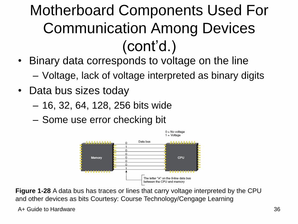
(cont’d.) • Binary data corresponds to voltage on the line
– Voltage, lack of voltage interpreted as binary digits
• Data bus sizes today
– 16, 32, 64, 128, 256 bits wide
– Some use error checking bit
Figure 1-28 A data bus has traces or lines that carry voltage interpreted by the CPU
and other devices as bits Courtesy: Course Technology/Cengage Learning
36
A+ Guide to Hardware
Motherboard Components Used For
Communication Among Devices
(cont’d.) • Data path size
– Width of a data bus
• Motherboard can have more than one bus
– Main motherboard bus
• Communicates with CPU, memory, chipset
• Also called system bus, front side bus (FSB), memory
bus, host bus, local bus, external bus
• System clock
– Dedicated to timing motherboard chip activities
– Quartz crystal generates oscillation
37
A+ Guide to Hardware
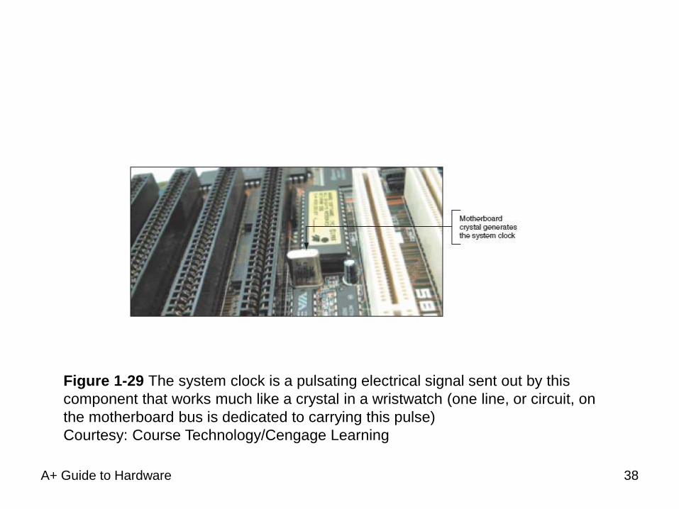
Figure 1-29 The system clock is a pulsating electrical signal sent out by this
component that works much like a crystal in a wristwatch (one line, or circuit, on
the motherboard bus is dedicated to carrying this pulse)
Courtesy: Course Technology/Cengage Learning
38
Motherboard Components Used For
Communication Among Devices
(cont’d.) • Devices work according to beats (or cycles)
• Clock speed measured in hertz (cycles/second)
– One megahertz (MHz): one million cycles per second
– One gigahertz (GHz): one billion cycles per second
• Common ratings for motherboard buses
– 2600 MHz, 2000 MHz, 1600 MHz, 1333 MHz, 1066
MHz, 800 MHz, 533 MHz, or 400 MHz
• Range of CPU speeds: 166 MHz to 4 GHz
• Buses for expansion slots: PCI, AGP, ISA
A+ Guide to Hardware 39
A+ Guide to Hardware
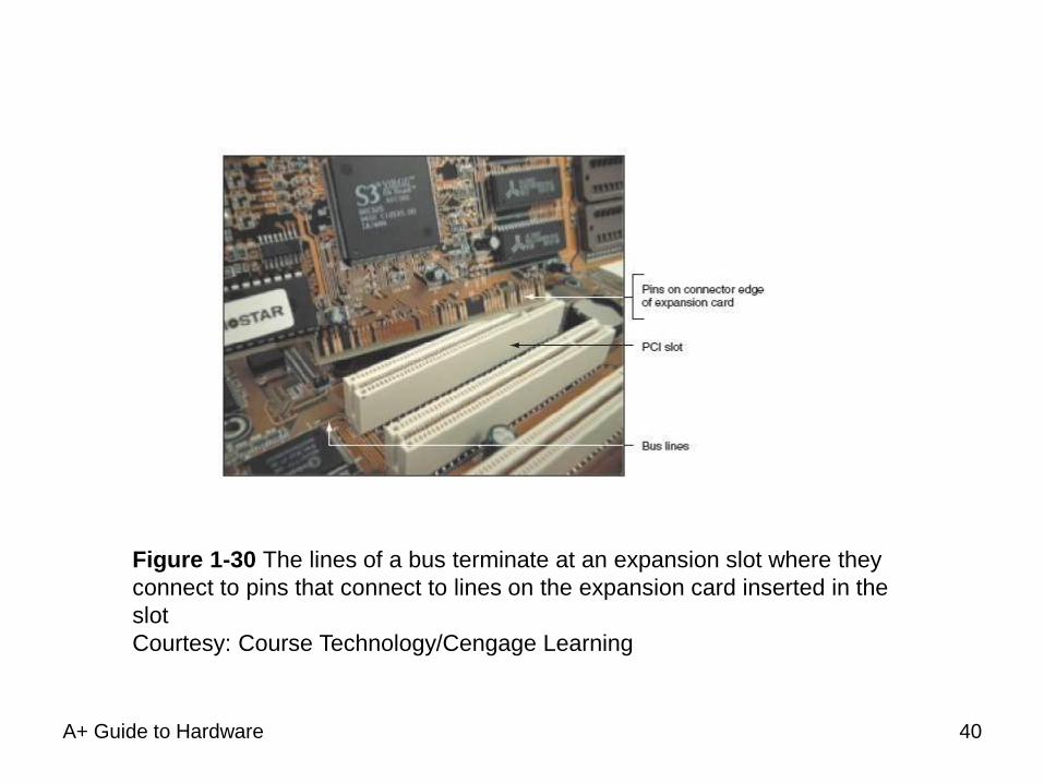
Figure 1-30 The lines of a bus terminate at an expansion slot where they
connect to pins that connect to lines on the expansion card inserted in the
slot
Courtesy: Course Technology/Cengage Learning
40
A+ Guide to Hardware
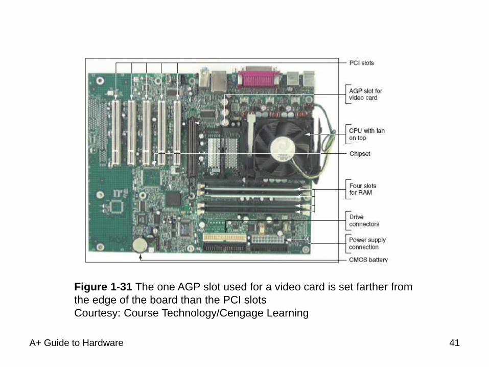
Figure 1-31 The one AGP slot used for a video card is set farther from
the edge of the board than the PCI slots
Courtesy: Course Technology/Cengage Learning
41
A+ Guide to Hardware
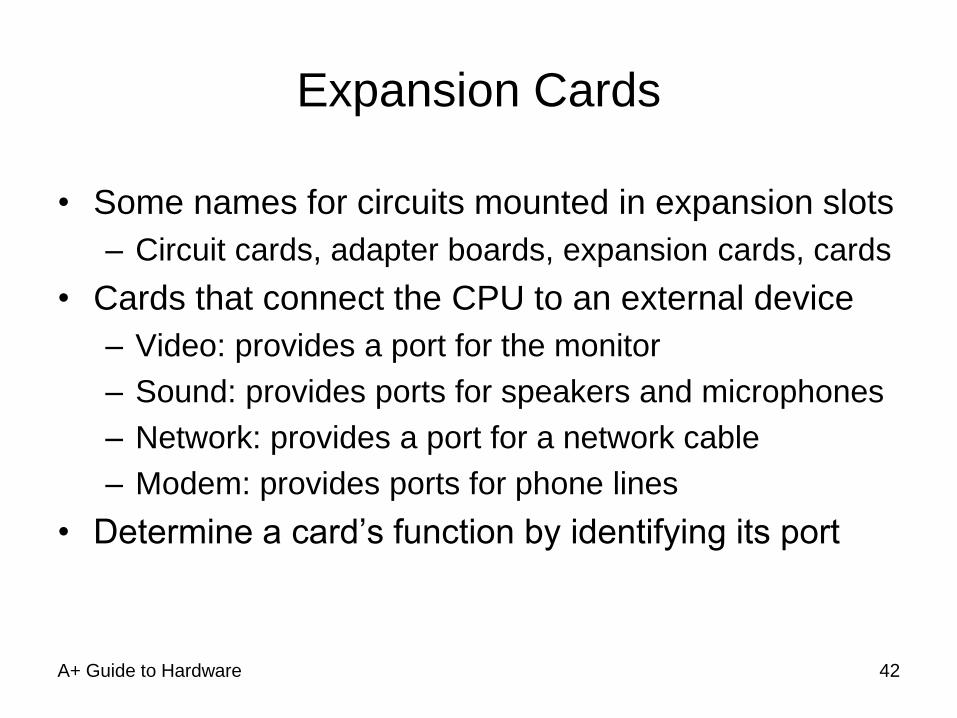
Expansion Cards
• Some names for circuits mounted in expansion slots
– Circuit cards, adapter boards, expansion cards, cards
• Cards that connect the CPU to an external device
– Video: provides a port for the monitor
– Sound: provides ports for speakers and microphones
– Network: provides a port for a network cable
– Modem: provides ports for phone lines
• Determine a card’s function by identifying its port
42
A+ Guide to Hardware
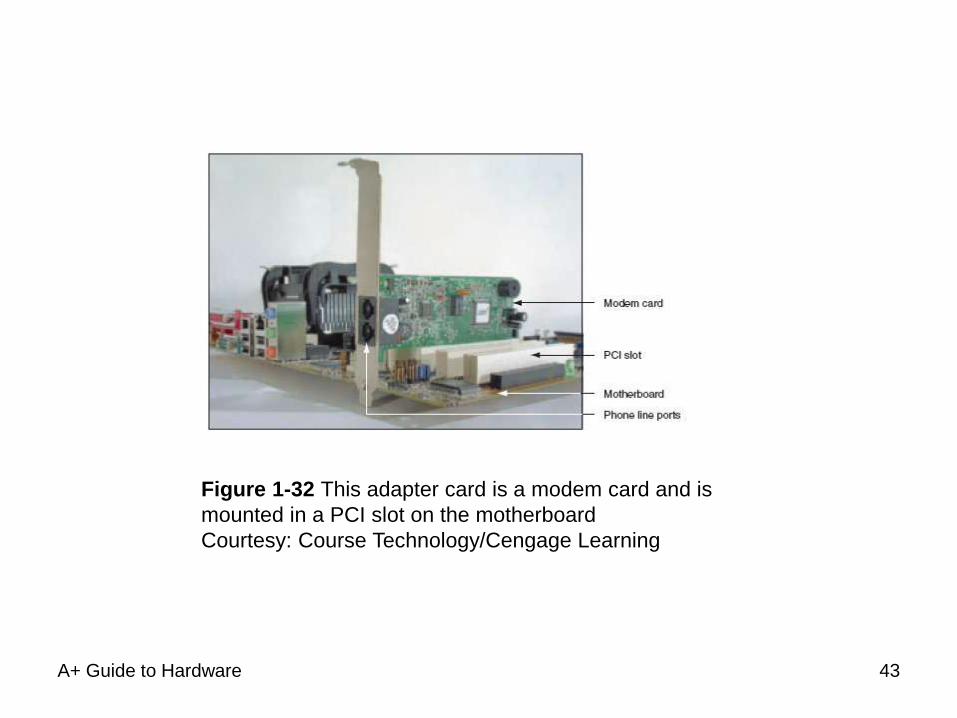
Figure 1-32 This adapter card is a modem card and is
mounted in a PCI slot on the motherboard
Courtesy: Course Technology/Cengage Learning
43
A+ Guide to Hardware
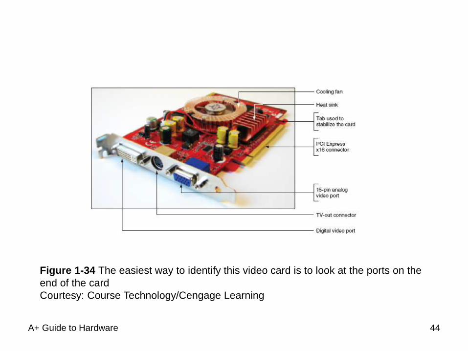
Figure 1-34 The easiest way to identify this video card is to look at the ports on the
end of the card
Courtesy: Course Technology/Cengage Learning
44
A+ Guide to Hardware
The Electrical System
• Power supply
– Most important electrical component
– Converts AC voltage external source to DC voltage
– Reduces voltage from 110-120 volts to 12 volts or less
– Runs a fan to cool the inside of the computer case
• Temperatures > 185° F can cause component failure
• Motherboard has 1 or 2 connections to power supply
45
A+ Guide to Hardware
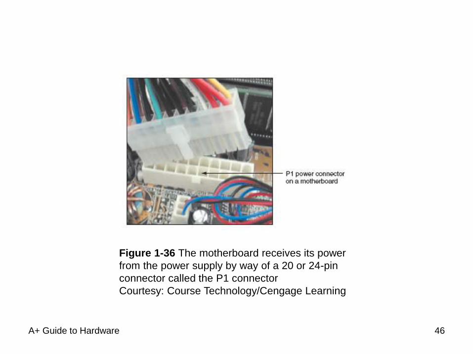
Figure 1-36 The motherboard receives its power
from the power supply by way of a 20 or 24-pin
connector called the P1 connector
Courtesy: Course Technology/Cengage Learning
46
Instructions Stored on the Motherboard
and Other Boards
• BIOS (basic input/output system)
– Data and instructions stored on ROM chips
– ROM BIOS chips: type of firmware
• Three purposes served by motherboard ROM BIOS
– System BIOS: manages simple devices
– Startup BIOS: starts the computer
– CMOS setup: changes motherboard settings
• CMOS RAM: includes date, time, port configurations
• Flash ROM
– ROM chips that can be overwritten
A+ Guide to Hardware 47
A+ Guide to Hardware
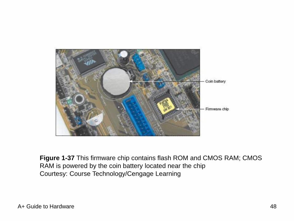
Figure 1-37 This firmware chip contains flash ROM and CMOS RAM; CMOS
RAM is powered by the coin battery located near the chip
Courtesy: Course Technology/Cengage Learning
48
A+ Guide to Hardware
Summary
• A computer comprises hardware and software
• Main functions
– Input, output, processing, storage
• Data stored in a binary format (one or zero, on or off)
• Input/output devices
– Keyboard, mouse, printer, monitor
• Motherboard (system board)
– Contains CPU, access to other circuit boards,
peripherals
49
A+ Guide to Hardware
Summary (cont’d.)
• Primary storage (RAM): volatile
• Secondary storage: nonvolatile
• Parallel and serial ATA standards
– Enable secondary storage devices to interface with the
motherboard
• Computer bus
– System of communication pathways, protocols
• ROM BIOS
– Helps start PCs; manages simple devices; changes
some motherboard settings
50
Top Related