
![INDEX []...INDEX Page 501-E01 CYLINDER, HEAD AND COVER 3 501-E02 PISTON/CRANKSHAFT 5 501-E03 INTAKE/ESHAUST 7 501-E04 WATER PUMP 11 501-E05 OIL PUMP 13 501-E06 OIL SYSTEM 15 501-E07](https://static.fdocuments.us/doc/165x107/5e9579482775034fef0cc642/index-index-page-501-e01-cylinder-head-and-cover-3-501-e02-pistoncrankshaft.jpg)


![AIRPORT STANDARDS DIRECTIVE 501 [ASD 501] · PDF fileairport standards directive 501 [asd 501] visual aids for navigation - aeronautical ground lights, electrical system & maintenance](https://static.fdocuments.us/doc/165x107/5a794a8d7f8b9ae93a8cbe98/airport-standards-directive-501-asd-501-standards-directive-501-asd-501-visual.jpg)


Languages
Pages
Legal


Solenoid Pilot Actuated Valves
501 Series Panel Mount
w w w . n u m a t i c s . c o m

Numatics, Inc. is a leading manufacturer of pneumatic products and motion control products. Our broad spectrum of standard, custom developed products and application components
have made a significant impact on pneumatic innovation as well as pneumatic and motion control
technology. Our company has an extensive history of generating innovative concepts and technological
breakthroughs. Many of today’s standard features in pneumatic technology were industry firsts from
Numatics. We continue our innovative approach to product development by developing electric motion
control solutions and enhancing our embedded Fieldbus and I/O products to continually meet and solve
our customer’s application requirements.
Today Numatics is proud to
be a part of the Industrial
Automation Division of
Emerson Electric Co.
Emerson (NYSE:EMR), based
in St. Louis, Missouri (USA),
is a global leader in bringing
technology and engineering
together to provide innovative
solutions for customers in
industrial, commercial, and
consumer markets through
its network power, process
management, industrial
automation, climate technologies,
and appliance and tools
businesses. For more information,
visit www.Emerson.com.

We are committed to providing you with an unmatched level of customer service, quality, and reliability. If you cannot locate the specific product for your application or need additional product specifications, visit www.numatics.com or call 888-686-2842. Numatics Express orders cannot be canceled or adjusted once entered. Saturdays, Sundays, and Holidays are excluded.
†As industry requirements change, Numatics reserves the right to modify the contents of this catalog and program without notification. Updates on this program can be obtained from the Numatics website www.numatics.com or by calling 888-686-2842, or by contacting your local Numatics representative or distributor and referencing the Numatics Express program.
*SentronicD Proportional Valves, CGT Compact Slides, NR Series Rodless and Air Bellows are limited to orders up to 5.**A Series Large Bore NFPA, ASP Series Steel Body NFPA and G Series Guide Rail Rodless are limited to orders up to 5.
Numatics Express Shipping Program guarantees† product shipment in two, three or five business days. Unlike most
traditional quick ship programs, the Numatics Express Shipping Program includes the most comprehensive offering in the industry. This program encompasses the range and options that you require!
Numatics is committed to offering you the highest level of customer service, quality and performance.
Numatics Express 2Day shipping program guarantees† product shipment in two business days. The program includes the most popular valve, air preparation and actuator products and includes applicable switches and mounting accessories.
Numatics guarantees† to ship any order received before 3 pm EST for up to 10 2Day products* in two business days.
Numatics Express shipping program offers a 3Day shipping program that guarantees† product shipment of a fully assembled and tested valve manifold in 3 business days. The program includes the most popular manifold configurations of the 2000 and Mark series valves:• Sub D, Terminal Strip and Fieldbus Electronic Options• Can be configured for DIN Rail Mounting and Muffled Exhaust• Shipped complete and 100% tested
The 3Day Express shipping program enables you to create a 2 to 8 station manifold assembly complete with any combination of valves, regulators, and blank stations that can be configured from the valve model charts in this catalog.
Numatics guarantees† to ship any order received before 3 pm EST for up to 5 manifold assemblies configured from this catalog in three business days or Numatics pays the shipping cost.
We are pleased to expand Numatics Express to include a broad range of products in a 5Day shipping program. Numatics guarantees† to ship up to 10 of any 5Day product** for orders received before 3 pm EST in 5 business days or Numatics pays the shipping cost.
i

Since 1945, Numatics has emerged as the prominent specialist in developing and manufacturing pneumatic and fluid power components for a widely diverse field of automated industry. From idea to implementation, leading engineers choose Numatics as their single source for:
• Quality Fluid Power components • Technologically advanced design resources • Quick response time in delivery and service from around the world
Welcome to the World of Fluid Automation...
CAD Modeling Save critical development time with the most innovative CAD configuration program in the pneumatic component industry. Numatics in 3D eliminates the time consuming process associated with designing components from scratch based on information found in conventional paper catalogs. The models are available in 85 different native CAD formats in 2D drawings and 3D models, including all the popular formats including Catia, I-DEAS, Pro/Engineer, SolidWorks, Unigraphics and more.
Numasizing® Developed by Numatics, Numasizing® offers a whole new level of fluid power system optimization. Compare large amounts of component and process data against user objectives and industry benchmarks for the best possible size, pneumatic pressure, actuator stroke velocities and other part and process variable determinations.
ii

1
Table of Contents
501 Series Features and Benefits 2 Technical and Operating Data 3 How to Order 4 Valve Regulator/Plug-in Assembly 5 Sandwich Pressure Regulator Dimensions 6 Manifold Assemblies 7 Plug-In Valve Mounted 7 Sandwich Shut Off Block 8 Blank Station Plate Kit 8 Speed Control Kit 8 DIN Rail Clamp Kit 9 Blocking Disc Kit 9 End Plate Kits 9 Manifold Assembly 10 Internal/External Pilot Selection 11
Assembly Kits How to Order 12 25 or 37 Pin Sub-D 13 1-32 Terminal Strip 14 19 Pin Round Connector 14
580 Series Features and Benefits 18 DeviceNet™ 19 Ethernet 20 Profibus DP 21 PROFINET 22 EtherCAT® 23 EtherNet/IP™ DLR 24 Dimensional Drawing - 580 Fieldbus Communication Assembly 25 How to Order - 580 Assembly Kit & 580 Electronics 26 How to Order Complete 580 Manifold Assemblies 27 Cables and Connectors 28-33
G3 Electronics Features and Benefits 36-37 G3 Platform Distribution Options 38-39 DeviceNet™ 40 Ethernet 41 PROFIBUS DP 42 PROFINET 43 CANopen® 44 DeviceLogix™ 45 Ethernet POWERLINK® 46 EtherCAT® and EtherNet/IP™ DLR 47-48 I/O Modules 49-51 Sub-Bus Modules 52-53 Miscellaneous Modules & Accessories 54-55 Dimensional Drawing - G3 Fieldbus Communication Assembly 56-57 How to Order Complete G3 Manifold Assemblies 58 How to Order - G3 Assembly Kit & G3 Electronics 59-60 Cables and Connectors 61-73 Example Sub-Bus Layout and Cabling 74

Information subject to change without notice. For ordering information or regarding your local sales office visit www.numatics.com.2
501SERIES
501 Series – Directional Control Valve Platform
Featuring Higher Flow in a Compact Valve Package
Commissioning Capabilities• Solenoid air pilot actuated
• Low wattage .8 wall for DC application
• DC solenoids Polarity insensitive with surge suppression
• Plug together circuit boards eliminate internal wiring
• Integral recessed gaskets
• IN Fittings to accommodate various tube sizes
• Simple conversion from internal to external pilot
• IP65 Certified
Panel Mount Options • Elimination of tubing and connections
• Adapter plate for direct mounting to cabinet walls
• Stainless steel or aluminum plate for 8, 12 or 16 station manifolds
• Shut off block for individual valve to be isolated from pressure supply during operation and repair
• Mid Station Supply Manifold block allows for multiple pressure zones (with blocking discs) or additional air supply to a manifold
Fieldbus Electronics Compatible• G3 Fieldbus Electronics
• Graphic Display for easy commissioning, visual status & diagnostics
• 32 valve solenoids per manifold
• Easy distribution of additional manifolds through Sub-Bus communication
• One Node supports up to 16 I/O modules
• Available with Auto Recovery Module (ARM) which allows configuration information to be saved and reloaded to replacement module automatically
• 580 Fieldbus Electronics
• Graphic Display for easy commissioning, visual status & diagnostics
• 32 valve solenoids per manifold
Information subject to change without notice. For ordering information or regarding your local sales office visit www.numatics.com.3
501SERIES
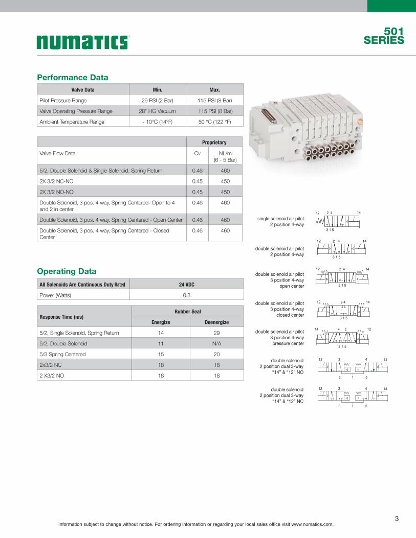
Performance Data
Operating Data
Valve Data Min. Max.
Pilot Pressure Range 29 PSI (2 Bar) 115 PSI (8 Bar)
Valve Operating Pressure Range 28" HG Vacuum 115 PSI (8 Bar)
Ambient Temperature Range - 10°C (14°F) 50 °C (122 °F)
Proprietary
Valve Flow Data Cv NL/m (6 - 5 Bar)
5/2, Double Solenoid & Single Solenoid, Spring Return 0.46 460
2X 3/2 NC-NC 0.45 450
2X 3/2 NO-NO 0.45 450
Double Solenoid, 3 pos. 4 way, Spring Centered- Open to 4 and 2 in center
0.46 460
Double Solenoid, 3 pos. 4 way, Spring Centered - Open Center 0.46 460
Double Solenoid, 3 pos. 4 way, Spring Centered - Closed Center
0.46 460
All Solenoids Are Continuous Duty Rated 24 VDC
Power (Watts) 0.8
Response Time (ms)Rubber Seal
Energize Deenergize
5/2, Single Solenoid, Spring Return 14 29
5/2, Double Solenoid 11 N/A
5/3 Spring Centered 15 20
2x3/2 NC 18 18
2 X3/2 NO 18 18
1412
3 1 5
2 4
1412
3 1 5
2 4
1412
3 1 5
2 4
1412
3 1 5
2 4
1214 24
3 1 5
single solenoid air pilot2 position 4-way
double solenoid air pilot2 position 4-way
double solenoid air pilot3 position 4-way
open center
double solenoid air pilot3 position 4-way
closed center
double solenoid air pilot3 position 4-waypressure center
12 142 4
3 1 5
12 142 4
3 1 5
double solenoid2 position dual 3-way
“14” & “12” NO
double solenoid2 position dual 3-way
“14” & “12” NC
(B)12
(A)14
(B)(A)2 4
3 1 5(EB)(P)(EA)
Information subject to change without notice. For ordering information or regarding your local sales office visit www.numatics.com.4
501SERIES
4501 A B
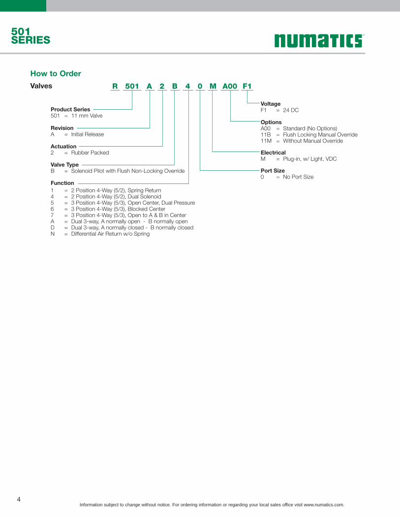
Product Series501 = 11 mm Valve
RevisionA = Initial Release
Actuation2 = Rubber Packed
Valve Type
Function
B = Solenoid Pilot with Flush Non-Locking Override
1 = 2 Position 4-Way (5/2), Spring Return4 = 2 Position 4-Way (5/2), Dual Solenoid5 = 3 Position 4-Way (5/3), Open Center, Dual Pressure6 = 3 Position 4-Way (5/3), Blocked Center7 = 3 Position 4-Way (5/3), Open to A & B in Center
D = Dual 3-way, A normally closed - B normally closedN = Differential Air Return w/o Spring
A = Dual 3-way, A normally open - B normally open
Voltage
OptionsA00 = Standard (No Options)11B = Flush Locking Manual Override11M = Without Manual Override
F1 = 24 DC
ElectricalM = Plug-in, w/ Light, VDC
Port Size0 = No Port Size
2 0 A00 F1R M
How to Order
Valves

Information subject to change without notice. For ordering information or regarding your local sales office visit www.numatics.com.5
501SERIES
2501 A P4
Port TypeH = Metric Thread
Product Series501 = 11 mm Valve
K = Push-In Fittings
RevisionA = Initial Release
Product Type
Electronics
M = Manifold Sub BaseZ = Mid Station Supply
Q4
P4
=
=
Manifold Sub Base, 4 Stations, Side Ports, Single Z-Board, Panel MountManifold Sub Base, 4 Stations, Side Ports, Double Z-Board Panel Mount
Interface1 = Proprietary
OptionsA00 = Standard (No Options)
M M 1 0A00 K
M = Plug-in, Receptacle AssemblyWiring Option
B = M7 (Threaded only)D = 4 mm (5/32) (Push-in Fittings only)F = 6 mm (Push-in Fittings only)2 = 1/4 (Push-in Fittings only)
Port Size
How to Order
501 Series MountingA
B
C
HG
FE
D
J
K
Plug In Valve Mounted
Dimensions: mm (Inches)
A B C D E F G H J K
76.4(3.008)
18.5(0.728)
6.5(0.256)
48(1.890)
42(1.653)
30(1.181)
18 (0.709)
6(0.236)
47(1.850)
105(4.134)

Information subject to change without notice. For ordering information or regarding your local sales office visit www.numatics.com.6
501SERIES
• Used to shut off pressure when mounted below valve.
• Allows easy maintenance without the need to shut off pressure to the entire manifold.
Sandwich Shut Off Block
Dimensions: mm (Inches)
A B C D E F G H
118.35(4.659)
91.35(3.596)
106.65(4.199)
22(0.866)
23.35 (0.919)
30.7(1.209)
23(0.906)
26.5(1.043)
Part Number Description
R501AY503875001 Proprietary Sandwich Shut Off Kit
Dimensions: mm (Inches)
A B C
105.1(4.138)
11(0.433)
15(0.591)
• Used to block off a manifold station for future use.
Blank Station Plate Kit
P501AB429685001
CB
A
(12)(3)(2)(1)(4)(5)(14)
(12)(3)(2)(1)(4)(5)(14)
A
B
C
D
E
F
G
H

Information subject to change without notice. For ordering information or regarding your local sales office visit www.numatics.com.7
501SERIES
DIN Rail Clamp Kit
239-980
Ports Part
1 P501AD431915001
3 P501AD431915002
5 P501AD431915003
1 + 3 P501AD431915004
1 + 5 P501AD431915005
3 + 5 P501AD431915006
1, 3, 5 P501AD431915007
Blocking Disc Kits
(Includes tag to label ports blocked)

Information subject to change without notice. For ordering information or regarding your local sales office visit www.numatics.com.8
501SERIES
Manifold AssemblyDimensions: mm (Inches)
A B C D E F G H J K L M N P Q R S T U V W
118(4.65)
105(4.13)
23(0.90)
32.3(1.27)
7.1(0.28)
59(2.32)
76.4(3.01)
48(1.89)
12.2(0.48)
72(2.83)
55.6(2.19)
41.1(1.62)
18.5(0.73)
15.9(0.63)
6.5(0.26)
14.3(0.56)
31.2(1.23)
43.2(1.70)
55.2(2.17)
67.2(2.65)
82.3(3.24)
D
E
DG
Q
P N
M
L
K
Ø5.3
B
F
C
H J
RB Ref.
A Ref.ST
UV
W

Information subject to change without notice. For ordering information or regarding your local sales office visit www.numatics.com.9
501SERIES
Internal Pilot External PilotInternal PilotSupply Plug Location
For External Pilot Supply Plug Location

Information subject to change without notice. For ordering information or regarding your local sales office visit www.numatics.com.10
501SERIES
Panel Mount How to OrderH501 A S
Port Type8 = NPTF
Product Series501 = 11 mm Valve
G = ISO228/1-GK = Push-In Fittings
RevisionA = Initial Release
Product Type
Plate Style
C = Panel Mount Assembly
SAV
===
316 Stainless SteelAluminum316 Stainless Steel with Vertical Shut Off
Number of Valve StationsH = 8L = 12P = 16
OptionsA00 = Standard (No Options)83F = External Mounting Flange
Fitting O-Ring0 = No FittingF = FKM O-RingN = NBR O-Ring
C 2 0 A00F NK
1 = 1/82 = 1/4G = 5/16H = 8 mm
Supply and Exhaust Ports, 1, 3/5 Port Size
B = M7 (Threaded only)D = 4 mm (5/32) (Push-in Fittings only)F = 6 mm (Push-in Fittings only)2 = 1/4 (Push-in Fittings only)
Cylinder Ports 2, 4 Port Size

Information subject to change without notice. For ordering information or regarding your local sales office visit www.numatics.com.11
501SERIES
*NOTE: Maximum number of valve stations is determined by:
• The electrical connection type.
• The valve type - single solenoid valves up to the maximum solenoid outputs allowed by the electrical connection type (see chart above) or a combination of single and/or double solenoid valves not to exceed the maximum number of solenoid outputs allowed.
• Combination of all stations cannot exceed 32 solenoids.
Maximum Solenoid Outputs
501 Series Panel Mount Assembly How to Order
Terminal Strip
25 PinSub-D
37 PinSub-D
19 Pin Round G3 Fieldbus 580 Fieldbus
32 22 32 16 32 32
VALVESTATIONS 1 2 3 4 22/32. . . .
VALVESTATIONS 1 2 3 4 22/32. . . .
25 or 37 Pin Sub-D, Terminal Strip and 19 Pin Round Connector• Shaded components described by Assembly Kit
model number designation.
• Each valve manifold station is listed in sequential
• order from left to right when facing the port side
• of the manifold as indicated.
Example Order - 501 Shown
25 Pin Sub-DValve Station #1 8501AVJ1H00PA00Valve Station #2 R501A2B10MA00F1Valve Station #3 R501A2B10MA00F1Valve Station #4 R501A2B10MA00F1Mounting #1 K501AMQ42MA0010Valve Station #5 R501A2B10MA00F1Valve Station #6 R501A2B10MA00F1Valve Station #7 R501A2B10MA00F1Valve Station #8 R501A2B10MA00F1Panel Mount Plate K501ACAH22N0A00 Assembled
D501 A 3
Port Type8 = NPTF
Product Series501 = 11 mm Valve
M = 37 Pin Sub-D Connector
G = ISO228/1-GK = Push-In Fittings
RevisionA = Initial Release
Product Type
Electronics
V = Valve Manifold Assembly
J = 25 Pin Sub-D Connector
T = Terminal Strip 1-32S = 580 Series Electronics
Q = 19 Pin Round Connector
Number of Valve StationsH = 8L = 12P = 16
OptionsA00 = Standard (No Options)DRM = DIN Rail Mount
End Plate StyleV = VerticalP = Panel Mount - Verticle End Plates
1 = 1/8
H = 8mm
Port Size
2 = 1/4G = 5/16
V 2 V A000 0K
3 = G3 Fieldbus Electronics

Information subject to change without notice. For ordering information or regarding your local sales office visit www.numatics.com.12
501SERIES
37 Pin Sub-D Connector Kit
Assembly Kits
25 Pin Sub-D Connector Kit
NOTE: External fusing or output protection recommended.
NOTE: External fusing or output protection recommended.
37 Pin Sub-D Connector Housing Kits
P599AE428442001 37 PIN SUB-D ASSEMBLY WITHOUT DIN RAIL
P599AE428442002 37 PIN SUB-D ASSEMBLY WITH DIN RAIL
25 Pin Sub-D Female Cable 22 AWG – Unshielded, Standard
Part Number Length
SC2502MCX00000000 2 Meters
SC2505MCX00000000 5 Meters
SC2510MCX00000000 10 Meters
37 Pin Sub-D Female Cable 22 AWG – Unshielded, StandardPart Number Length
SC3702MCX00000000 2 Meters
SC3705MCX00000000 5 Meters
SC3710MCX00000000 10 Meters
25 Pin Sub-D Connector Housing Kits
P599AE428441001 25 PIN SUB-D ASSEMBLY WITHOUT DIN RAIL
P599AE428441002 25 PIN SUB-D ASSEMBLY WITH DIN RAIL
A
B C
Ø5.5
G
H
J
K
F
E D
Dimensions: mm (Inches)
A B C D E F G H J K
46.4(1.827)
17(0.669)
6.7(0.26)
118(4.65)
37.5(1.48)
59(2.32)
40.2(1.58)
40.2(1.58)
68.1(2.68)
24.4(0.96)
A
B C
Ø5.5
G
H
J
K
F
E D
Dimensions: mm (Inches)
A B C D E F G H J K
46.4(1.827)
17(0.669)
6.7(0.26)
118(4.65)
37.5(1.48)
59(2.32)
40.2(1.58)
40.2(1.58)
68.1(2.68)
24.4(0.96)
NDB25F22U02MSB4 2 Meters
NDB25F22U05MSB4 5 Meters
NDB25F22U10MSB4 10 Meters
37 Pin Sub-D Female Cable 22 AWG – Unshielded IP65NDB37F22U02MSB4 2 Meters
NDB37F22U05MSB4 5 Meters
NDB37F22U10MSB4 10 Meters

Information subject to change without notice. For ordering information or regarding your local sales office visit www.numatics.com.13
501SERIESAssembly Kits
1-32 Terminal Strip Kit
NOTE: External fusing or output protection recommended.NOTE: Min. Wire AWG 26 Max. Wire AWG 18
1 – 32 Terminal Strip Housing Kits
P599AE428444001 TERMINAL STRIP ASSEMBLY WITHOUT DIN RAIL
P599AE428444002 TERMINAL STRIP ASSEMBLY WITH DIN RAIL
19 Pin Round Connector Housing Kits
P599AE428436001 19 PIN ASSEMBLY WITHOUT DIN RAIL
P599AE428436002 19 PIN ASSEMBLY WITH DIN RAIL
19 Pin Round Connector Kit
19 PIN CONNECTOR
PIN 10= COIL 14PIN 9= COIL 10PIN 8= COIL 6PIN 7= COIL 2PIN 6= COMMONPIN 5= COIL 3PIN 4= COIL 4PIN 3= COIL 7PIN 2= COIL 11PIN 1= COIL 15
PIN 19= N.C.
PIN 11= COIL 13PIN 12= P.E.PIN 13= COIL 12PIN 14= COIL 8PIN 15= COIL 1PIN 16= COIL 5PIN 17= COIL 9PIN 18= COIL 16
NOTE: External fusing or output protection recommended.
Ø5.2
A
C
D
N
P
K Q
J
1/2 NPTF Tap
E
F G
Dimensions: mm (Inches)
A C D E F G J K N P Q
82.7(3.256)
7(0.28)
118(4.65)
37.5(1.48)
59(2.32)
40.2(1.583)
68.1(2.68)
24.4(0.96)
9.8(0.39)
41.9(1.65)
19.3(0.76)
A
C
E
G
D
K
J
L
M
Dimensions: mm (Inches)
A C D E G J K L M
56.3(2.217)
6.7(0.26)
118(4.65)
37.5(1.48)
40.2(1.583)
68.1(2.68)
24.4(0.96)
40.8(1.61)
59(2.323)
19 Pin M23 Female Cable
Part Number Length
CC1905MI00000000 5 Meters
CC1910MI00000000 10 Meters

Information subject to change without notice. For ordering information or regarding your local sales office visit www.numatics.com.14
501SERIES Notes

Information subject to change without notice. For ordering information or regarding your local sales office visit www.numatics.com.15
501SERIESNotes

World Class Supplier of Pneumatic Components
World Headquarters
Numatics, Inc. | Tel (248) 596-3200 | www.numatics.com | email: [email protected] Rev 03/15 10K-Walsworth-08/12© Numatics Inc. 2012-2013 Numatics® is registered in the United States and elsewhere
USA Numatics, Incorporated46280 Dylan DriveNovi, Michigan 48377
P: 248-596-3200 F: 248-596-3201
Canada Numatics, LtdP: 519-758-2700 F: 519-758-5540
Brazil Ascoval Ind.e Comercio LtdaP: (55) 11-4208-1700 F: (55) 11-4195-3970
México - Ascomatica SA de CVP: 52 55 58 09 56 40 (DF y Area metropolitana)P: 01 800 000 2726 (Interior de la República) F: 52 55 58 09 56 60
Top Related