


Languages
Pages
Legal


Fiche technique / Technical sheet UT‐5000
Applica on Résiden elle, Ins tu onnelle, Commerciale et Industrielle
Residen al, Ins tu onnal, Commercial and Industrial
Usage Moyen/Robuste—Medium/Heavy duty
Norme / Standard Conforme—Complies with ANSI/BHMA A156.14 Grade 1
Fiche technique/ Technical sheet UT‐5000
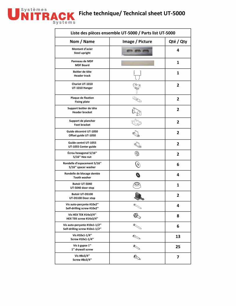
Liste des pièces ensemble UT‐5000 / Parts list UT‐5000
Nom / Name Image / Picture Qté / Qty
Montant d’acier
Steel upright 4
Panneau de MDF
MDF Board 1
Boi er de tête
Header track 1
Chariot UT‐1010
UT‐1010 Hanger 2
Plaque de fixa on
Fixing plate 2
Support boi er de tête
Header bracket 2
Support de plancher
Foot bracket 2
Guide décentré UT‐1050
Offset guide UT‐1050 2
Guide centré UT‐1055
UT‐1055 Center guide 2
Écrou hexagonal 5/16’’
5/16’’ Hex nut 2
Rondelle d’espacement 5/16’’
5/16’’ spacer washer 6
Rondelle de blocage dentée
Tooth washer 4
Butoir UT‐5040
UT‐5040 door stop 1
Butoir UT‐DS100
UT‐DS100 Door stop 2
Vis auto‐perçante #10x2’’
Self‐drilling screw #10x2’’ 4
Vis HEX TEK #14x3/4’’
HEX TEK screw #14x3/4’’ 8
Vis auto‐perçante #10x1‐1/2’’
Self‐drilling screw #10x1‐1/2’’ 6
Vis #10x1‐1/4’’
Screw #10x1‐1/4’’ 13
Vis à gypse 1’’
1’’ drywall screw 25
Vis #8x3/4’’
Screw #8x3/4’’ 7
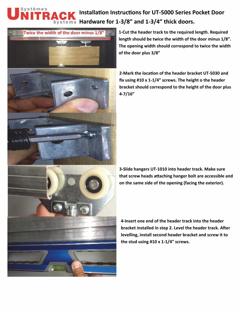
Installa on Instruc ons for UT‐5000 Series Pocket Door
Hardware for 1‐3/8” and 1‐3/4” thick doors.
1‐Cut the header track to the required length. Required
length should be twice the width of the door minus 1/8”.
The opening width should correspond to twice the width
of the door plus 3/8”
2‐Mark the loca on of the header bracket UT‐5030 and
fix using #10 x 1‐1/4” screws. The height o the header
bracket should correspond to the height of the door plus
4‐7/16”
3‐Slide hangers UT‐1010 into header track. Make sure
that screw heads a aching hanger bolt are accessible and
on the same side of the opening (facing the exterior).
4‐Insert one end of the header track into the header
bracket installed in step 2. Level the header track. A er
levelling, install second header bracket and screw it to
the stud using #10 x 1‐1/4” screws.
Installa on Instruc ons for UT‐5000 Series Pocket Door
Hardware for 1‐3/8” and 1‐3/4” thick doors.
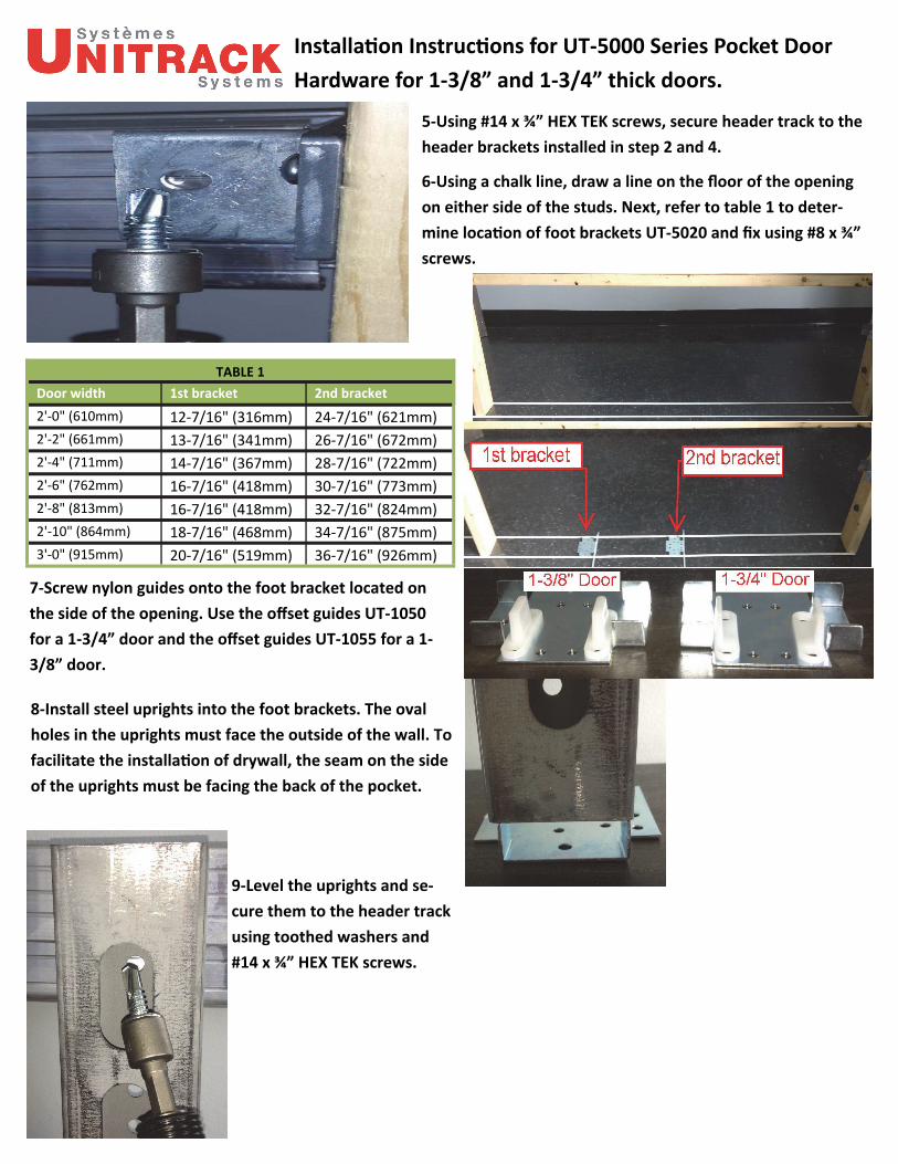
5‐Using #14 x ¾” HEX TEK screws, secure header track to the
header brackets installed in step 2 and 4.
6‐Using a chalk line, draw a line on the floor of the opening
on either side of the studs. Next, refer to table 1 to deter‐
mine loca on of foot brackets UT‐5020 and fix using #8 x ¾”
screws.
Door width 1st bracket 2nd bracket
2'‐0" (610mm) 12‐7/16" (316mm) 24‐7/16" (621mm)
2'‐2" (661mm) 13‐7/16" (341mm) 26‐7/16" (672mm)
2'‐4" (711mm) 14‐7/16" (367mm) 28‐7/16" (722mm)
2'‐6" (762mm) 16‐7/16" (418mm) 30‐7/16" (773mm)
2'‐8" (813mm) 16‐7/16" (418mm) 32‐7/16" (824mm)
2'‐10" (864mm) 18‐7/16" (468mm) 34‐7/16" (875mm)
3'‐0" (915mm) 20‐7/16" (519mm) 36‐7/16" (926mm)
TABLE 1
7‐Screw nylon guides onto the foot bracket located on
the side of the opening. Use the offset guides UT‐1050
for a 1‐3/4” door and the offset guides UT‐1055 for a 1‐
3/8” door.
8‐Install steel uprights into the foot brackets. The oval
holes in the uprights must face the outside of the wall. To
facilitate the installa on of drywall, the seam on the side
of the uprights must be facing the back of the pocket.
9‐Level the uprights and se‐
cure them to the header track
using toothed washers and
#14 x ¾” HEX TEK screws.

Installa on Instruc ons for UT‐5000 Series Pocket Door
Hardware for 1‐3/8” and 1‐3/4” thick doors.
10–Cut the MDF panel to the required length, which should be the door
width minus ¾”. Fasten it to the header track on the side of the opening sec‐
on using #10 x 1‐1/2” screws (3 per panel)
11a: Drill a 3/8” diameter hole at least 1‐1/2” deep at 3‐
1/2” from each edge of the door.
11b: Drill a 1/8” diameter hole at least 1” deep for the
fixing plates.
12‐Centre the fixing plate, flat side up, over the
pre‐drilled hole.
13‐Screw on the fixing plates using #10 x 1‐1/4” screws.
14‐Unscrew the a achment plates for the fastening
bolt. 15‐Screw the 5/16” hex nut onto the bolt.
16‐Screw the fastening
bolt into the fixing plate.
17‐Posi on the door under the hangers and insert the
fastening bolts into the a achment sleeves.

Installa on Instruc ons for UT‐5000 Series Pocket Door
Hardware for 1‐3/8” and 1‐3/4” thick doors
18‐Re‐fasten the a achment plates removed in
step 14. DO NOT OVER‐TIGHTEN.
19‐Set the door level and adjust its height by
screwing or unscrewing the hex part of the bolt.
Once adjustment is made, lock the bolt by
ghtening the 5/16” hex nut.
20‐Install the stopper UT‐5040 to mid‐height of the
stud at the back of the pocket. When the door is in
the open posi on, it will be cushioned by the stop‐
per. Depending on the type of trim used, it may be
required to shim the stopper with 3/16” washers.
21‐Slide the stopper UT‐DS100 into the rail at the desired stop point and
a ach to rail using #10 x 2” screws.
22‐Complete the installa on by installing the drywall and mouldings. These items are supplied by others.
Steel upright x4
MDF board x1
Header UT‐5000
HangerUT‐1010 x2
Fixing plate x2
Header bracket x2
Parts list for UT‐5000 series:
Floor bracket x2
HEX TEK screw #14x3/4’’ x8
Tooth washer x4
Offset guide UT‐1050 x2
Center guide UT‐1055 x2
Stop UT‐5040 x1
Stop UT‐DS100 x2
5/16’’ Hex nut x2
Spacer washer x6
Self‐drilling screw #10x1‐1/2’’ x6
Self‐drilling screw #10x2’’ x4
Screw #10x1‐1/4’’ x13
Screw #8x3/4’’ x10
Drywall screw 1’’ x25
Top Related