


Languages
Pages
Legal

International Journal of Electrical Engineering and Technology (IJEET), ISSN 0976 –
6545(Print), ISSN 0976 – 6553(Online) Volume 4, Issue 2, March – April (2013), © IAEME
344
UNDERSTANDING OPERATION OF SHUNT CAPACITORS AND
OLTC FOR TRANSMISSION LOSS REDUCTION
Dr. M. P. Sharma Sarfaraz Nawaz
AEN, RVPNL, Jaipur Assoc. Prof., EE Deptt., SKIT, Jaipur
ABSTRACT
This paper presents an understanding operation of shunt capacitor banks and OLTC in
various power system conditions for reactive power control in power transmission system to
reduce transmission losses, power system elements loading and voltage control. This paper
also presents efficient use of existing shunt capacitor banks for voltage-var control in power
transmission system in order to avoid installation of new devices allowing economy of
operation. The procedure has been simulated to the Rajasthan power transmission system
model having 750 buses, 6800MWsystem load and 3200MVAR capacity shunt capacitor
banks installed at various 33KV and 11KV load buses in order to verify its effectiveness.
Rajasthan power system has been modeled using Mi-Power power system analysis software
designed by the M/s PRDC Bangalore. Results of tests conducted on the model system in
various possible field conditions are presented and discussed. Simulation results compared
with that obtaining using existing methods for operations of shunt capacitor banks & OLTC
attach with power transformers for reactive power and voltage control are presented to show
the potential of application of the proposed methods to power system economical operation.
(I) INTRODUCTION
Rapid rise in load growth in the Rajasthan system led to fast expansion of the
Rajasthan Electrical Network. Total transmission system network at the end of financial year
for last three years is placed at Table-1.
INTERNATIONAL JOURNAL OF ELECTRICAL ENGINEERING
& TECHNOLOGY (IJEET)
ISSN 0976 – 6545(Print) ISSN 0976 – 6553(Online) Volume 4, Issue 2, March – April (2013), pp. 344-357
© IAEME: www.iaeme.com/ijeet.asp Journal Impact Factor (2013): 5.5028 (Calculated by GISI) www.jifactor.com
IJEET
© I A E M E

International Journal of Electrical Engineering and Technology (IJEET), ISSN 0976 –
6545(Print), ISSN 0976 – 6553(Online) Volume 4, Issue 2, March – April (2013), © IAEME
345
Table-1: Total transmission network at the end of financial year
Particulars 31-3-09 31-3-10 31-3-11
400 kV S/S
(Nos/MVA)
4(2955) 7(3900) 9(4895)
400 kV
Lines
(ckt kms)
1358 1945 2660
220 kV S/S
(Nos/MVA)
62(11855) 66(12955) 74(15405)
200 kV
Lines
(ckt kms)
9321 10067 10662
132 kV S/S
(Nos/MVA)
280(14151) 292(15871) 310(18174)
132 kV
Lines
(ckt kms)
12776 13193 13852
(II) TRANSMISSION LOSSES WITHIN STATE
For Rajasthan Power System, recorded peak load (MW) & reactive power demand
and transmission losses within the state in the past few years have been tabulated at Table-2.
Table-2: Transmission lossess within state
FY 2007-
08
2008-
09
2009-
10
2010-
11
Recorded peak
load (MW)
5564 6101 6859 7442
Load Reactive
Power
Demand
(MVAR)
4173 4575 5144 5581
%Transmission
losses
4.61% 4.34% 4.43 4.40
To compensate the load reactive power demand, capacitor banks have been installed
at 33 kV (at 132/33 kV GSS’s), 11 kV (at 33/11 kV GSS’s) and LT voltage levels. As on
31.3.2011, 3200 MVAR capacity capacitors banks have been installed in the Rajasthan
system at 33 kV voltage level. Rating of most of capacitor Banks is 5.43 MVAR at 33 kV
voltage level. At 220 kV & 132 kV substations, for voltage and power factor control two
devices are available:-
• On Load Tap Changers provided on EHV Transformers
• Shunt capacitor banks installed at 33 kV voltage level
When to operate OLTC & when the capacitor bank is big question??. Understanding and
coordinated operation of OLTC and capacitor banks results reduction in system losses,
improved voltage profile and reduce MVA loading of transformers & transmission lines.

International Journal of Electrical Engineering and Technology (IJEET), ISSN 0976 –
6545(Print), ISSN 0976 – 6553(Online) Volume 4, Issue 2, March – April (2013), © IAEME
346
To understand impact of operation of OLTC & capacitor banks in different operating
conditions on voltage profile, system losses and MVA Loading of transformer and
transmission lines some simulation studies have been carried and presented. Rajasthan power
system has been selected to carry out the simulation studies. Rajasthan power system has
been represented up to 33 kV voltage level using the Mi-Power software. Load and capacitor
banks have been lumped at 33 kV buses at 220 kV and 132 kV sub-stations. All transmission
lines above 132 kV voltage level and all 400/220 kV, 220/132 kV & 132/33 kV
transformers have been represented. 132 kV GSS Lalsot has been selected to show the effect
of OLTC operation and shunt capacitor banks operation in different operating
conditions. 132 kV sub-station Lalsot is presently connected to 220 kV sub-station Dausa via
35 kM long 132 kV S/C line. Details of power system Equipment's installed at 132kV Lalsot
are as follows:-
Transformers capacity
• 132/33kV 1x40/50 MVA Transformer: Total No. of taps :1-5-9, 10 % impedance
• 132/33kV 1x20/25 MVA Transformer: Total No. of taps :1-5-9, 10 % impedance
Capacitor Banks Capacity
• 1x5.43MVAR, 33kV Voltage Shunt Capacitor Bank-1
• 1x5.43MVAR, 33kV Voltage Shunt Capacitor Bank-2
• 1x5.43MVAR, 33kV Voltage Shunt Capacitor Bank-3
132kV S/C Dausa- Lalsot line: 35kM
(III) CASE STUDY-1: BENEFITS OF SHUNT CAPACITOR BANKS
Power plots of load flow study with 45 MW, 0.80 PF load at 33 kV bus (505) is
placed at LFS Plots-1. Under this condition reactive power drawal of 33 kV Bus(505) from
Grid is approximately 20 MVAR. Power plots of LFS with 4th
1x5.43 MVAR, 33 kV
Capacitor Bank at 33 kV Bus(505) while other conditions are remain unchanged is placed at
LFS Plots-2.
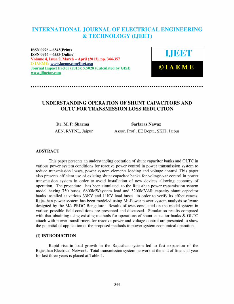
Fig. :1 LFS Plot1: With three Capacitor Banks at 33 kV Bus ( 505)
International Journal of Electrical Engineering and Technology (IJEET), ISSN 0976 –
6545(Print), ISSN 0976 – 6553(Online) Volume 4, Issue 2, March – April (2013), © IAEME
347
Fig. 2: LFS Plot 2: With four Capacitor Banks at 33 kV Bus ( 505)
Impact of 4th
Shunt Capacitor Banks on reactive power flow, transmission losses,
system voltage and system element loading have been analyzed.
• Impact on Reactive Power Flow
Reactive flow
on
With three
Capacitor Banks
With four
Capacitor Banks
132/33 kV
Transformers
20.99 MVAR 16.34 MVAR
132kV line 22.76 MVAR 17.79 MVAR
220/132kV
Transformers
91.09 MVAR 85.09 MVAR
• Impact on voltage profile
Particulars With three
Capacitor
Banks
With four
Capacitor
Banks
33 kV bus voltage 29.21 kV 29.55 kV
132 kV bus voltage 117.76 kV 118.93 kV
220 kV bus voltage 214.52 kV 214.81 kV

International Journal of Electrical Engineering and Technology (IJEET), ISSN 0976 –
6545(Print), ISSN 0976 – 6553(Online) Volume 4, Issue 2, March – April (2013), © IAEME
348
• Impact on Transformers and transmission lines loading
Particulars With three
Capacitor Banks
With four
Capacitor
Banks
132/33 kV transformers
loading
50.05 MVA 48.17 MVA
132 kV line loading 51.37 MVA 49.28 MVA
220/132 kV transformers
loading
168.51 MVA 165.19 MVA
• Impact on Transmission losses
Particulars With three
Capacitor
Banks
With four
Capacitor
Banks
Total losses in 132kV
network (Line+Tranf.)
1.06 MW 0.96 MW
• Saving in transmission losses in 132kV network
due to fourth Capacitor bank : 0.10 MW
• Saving in transmission losses in 220kV & above
network due to fourth capacitor bank: 2.5x0.1
• Saving in transmission losses in 132kV network
due to fourth Capacitor bank : 0.10 MW
• Saving in total transmission losses due to fourth capacitor bank: 0.10 + 0.25 = 0.35 MW
• Yearly Energy Saving: 30.66 LUs
• Saving in terms of rupees: 30.66x2.0 = Rs. 61.32 Lacs/annum
This study indicates that With 4th
unit of shunt capacitor bank
• Voltages of 220 kV, 132 kV & 33 kV buses have been improved
• Loading on transformers & transmission line has been reduced.
• Transmission losses have been reduced.
Therefore, capacity of Capacitor Banks at load Bus should be comparable to Bus
reactive Power Demand in order to reduce the system losses and system elements
loading.
(IV) CASE STUDY-2: CONTROL OF HIGH VOLTAGE BY CAPACITOR BANKS
VS OLTC OPERATION
Power plots of LFS with 33 MW, 0.80 PF load at 33 kV bus(505) is placed at LFS
plots-3. Under this condition voltage of 33 kV bus(505) is above the 5% of nominal voltage.
This 33 kV bus high voltage can be reduced either by switching off one capacitor bank or
decreasing the transformer ratio with the help of OLTC. Power plots of LFS for voltage
control through one capacitor bank switching OFF and transformer tap ratio reduction is
International Journal of Electrical Engineering and Technology (IJEET), ISSN 0976 –
6545(Print), ISSN 0976 – 6553(Online) Volume 4, Issue 2, March – April (2013), © IAEME
349
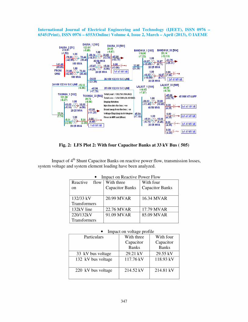
placed at LFS plots-4 & 5 respectively. Impact of 33 kV Bus (505) voltage control through
Capacitor Bank switching (Case-1) vs OLTC operation (Case-2) on reactive power flow,
transmission losses, system voltage and system element loading have been analyzed.
• Impact on Reactive Power Flow
Reactive flow
on
Capacitor Bank
operation
OLTC
Operation
132/33 kV
Transformers
12.99 MVAR 8.12 MVAR
132kV line 13.30 MVAR 8.42 MVAR
220/132kV
Transformers
37.12 MVAR 31.62 MVAR
• Impact on voltage profile
Particulars Capacitor
Bank
operation
OLTC
Operation
33 kV bus voltage 34.34 kV 33.34 kV
132 kV bus voltage 132.70 kV 133.72 kV
220 kV bus voltage 224.13 kV 224.38 kV
• Impact on Transformers and transmission lines loading
Particulars Capacitor
Bank
operation
OLTC
Operation
132/33 kV
transformers loading
35.59 MVA 34.07 MVA
132 kV line loading 35.64 MVA 34.19 MVA
220/132 kV
transformers loading
109.34
MVA
107.55
MVA
• Impact on Transmission losses
Particulars Capacitor
Bank
operation
OLTC
Operation
Total losses in 132kV
network (Line+Tranf.)
0.42 MW 0.38 MW

International Journal of Electrical Engineering and Technology (IJEET), ISSN 0976 –
6545(Print), ISSN 0976 – 6553(Online) Volume 4, Issue 2, March – April (2013), © IAEME
350
• Saving in transmission losses in 132kV network in Case-2 as compared to Case-1: 0.04
MW
• Saving in transmission losses in 220kV & above network in Case-2 as compared to
Case-1:
= 2.5 x 0.04 MW = 0.10 MW
• Saving in total transmission losses in Case-2 as compared to Case-1: 0.14 MW
• Yearly Energy Saving in Case-2 as compared to Case-1 for four hours: 2.04 LUs
• Saving in terms of rupees: 2.04 x2.00 = Rs 4.08 lacs/annum
This study indicates that under lagging power factor of a bus, control of high bus voltage
through switching OFF capacitor Bank instead of OLTC operation results:
• Increase the reactive power flow on Transformers and Transmission lines
• Increase the MVA loading on transformers & transmission lines.
• Reduction in 132 kV & 220 kV voltages which may be already low in some system
conditions.
• Increase the total system losses which results loss of revenue.
Fig. 3: LFS Plot 3: Base Case with high 33 kV Bus (505) Voltage
Fig. 4: LFS Plots 4: Control of high 33 kV Bus(505) voltage through switched off one
Capacitor Bank

International Journal of Electrical Engineering and Technology (IJEET), ISSN 0976 –
6545(Print), ISSN 0976 – 6553(Online) Volume 4, Issue 2, March – April (2013), © IAEME
351
Fig. 5 : LFS Plot 5: Control of high 33 kV Bus(505) voltage by reduction in
Transformers Tap ratio from 1.04 PU to 1.0 PU
Therefore, in lagging power factor condition, high voltage of a Bus should be
regulated through OLTC operation instead of switching OFF the Capacitor Banks in
order to reduce the system losses and system elements loading.
(V) CASE STUDY-3: OPTIMUM UTILIZATION OF CAPACITOR BANKS
Power plots of LFS with 45 MW, 0.80 PF load at 33 kV bus(505) is placed at LFS
plots-6. Under this condition
• Voltage of 33 kV bus(505) is 27.74 kV
• Reactive power flow on 132 kV transformers is 22.24 MVAR
• 132/33 kV Transformers tap position is 1.0 PU
• Capacitor banks are injecting 13.65 MVAR against the 16.29 MVAR connected
capacity.
Now transformer ratio of 132/33 kV transformers connected to 33 kV Bus(505) is increased
from 1.0 PU (Case-1) to 1.05 PU (1/0.95) (Case-2) while other system conditions remain
unchanged. Power plots of LFS with increase transformers ratio is placed at LFS plots-7.
Impact of rise in transformer tap ratio on reactive power flow, transmission losses, system
voltage and system element loading have been analyzed.
• Impact on Reactive Power Flow
Reactive flow on Transformer
Ratio:1.00PU
Transformer
Ratio:1.05PU
Output of Capacitor
Banks connected to
Bus(505)
13.65 MVAR 15.48 MVAR
132/33 kV
Transformers
23.94 MVAR 21.57 MVAR
132kV line 24.48 MVAR 21.98 MVAR
220/132kV
Transformers
84.89 MVAR 81.92 MVAR
International Journal of Electrical Engineering and Technology (IJEET), ISSN 0976 –
6545(Print), ISSN 0976 – 6553(Online) Volume 4, Issue 2, March – April (2013), © IAEME
352
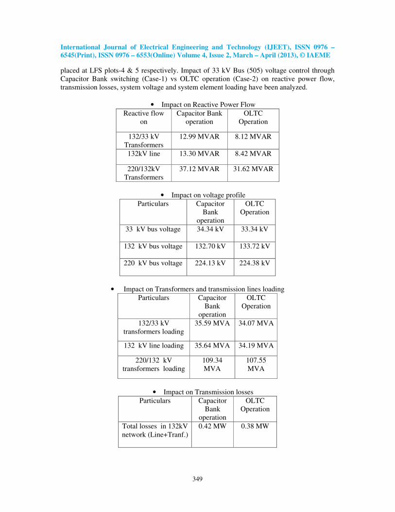
• Impact on voltage profile
Particulars Transformer
Ratio:1.00PU
Transformer
Ratio:1.05PU
33 kV bus voltage 30.22 kV 32.18 kV
132 kV bus voltage 125.46 kV 126.01 kV
220 kV bus voltage 226.10 kV 226.23 kV
• Impact on Transformers and transmission lines loading
Particulars Transformer
Ratio:1.00PU
Transformer
Ratio:1.05PU
132/33 kV
transformers loading
51.13 MVA 50.05 MVA
132 kV line loading 52.21 MVA 51.02 MVA
220/132 kV
transformers
loading
165.01 MVA 163.42 MVA
• Impact on Transmission losses
Particulars Transformer
Ratio:1.00PU
(Case-1)
Transformer
Ratio:1.05PU
(Case-2)
Total losses
in 132kV
network
(Line+Tranf.)
1.12 MW 1.05 MW
• Saving in transmission losses in 132kV network in Case-2 as compared to Case-1: 0.07
MW
• Saving in transmission losses in 220kV & above network in Case-2 as compared to
Case-1:
= 2.5 x 0.07 MW = 0.175 MW
• Saving in total transmission losses in Case-2 as compared to Case-1: 0.245 MW
• Yearly Energy Saving in Case-2 as compared to Case-1 for four hours: 3.57 LUs
• Saving in terms of rupees: 3.57 x2.00 = Rs 7.14 lacs/annum
This study indicates that rise in transformer tap ratio
under low load bus voltage condition increase the output of the connected capacitor banks
which results:
• Decrease the reactive power flow on Transformers and Transmission lines
• Decrease the MVA loading on transformers & transmission lines.
• Increase the 33 kV, 132 kV & 220 kV voltages which may be already low in some
system conditions..
• Decrease the total system losses.

International Journal of Electrical Engineering and Technology (IJEET), ISSN 0976 –
6545(Print), ISSN 0976 – 6553(Online) Volume 4, Issue 2, March – April (2013), © IAEME
353
Fig. 6 :LFS Plot 6: 1.0 PU tap ratio of 132/33 kV Transformers connected to 33 kV
Bus(505)
Fig. 7 : LFS Plot 7: 1.05 (1/0.95) PU tap ratio of 132/33 kV Transformers connected to
33 kV Bus(505)
Therefore, load bus voltage should be maintained near to nominal with the variation of
transformer ratio using OLTC unit for optimum utilization of Shunt Capacitor Banks
to reduce the system losses.
(VI) CASE STUDY-4: EFFECT OF OLTC OPERATION OF 220/132 KV
TRANSFORMERS ON TRANSMISSION LOSSES
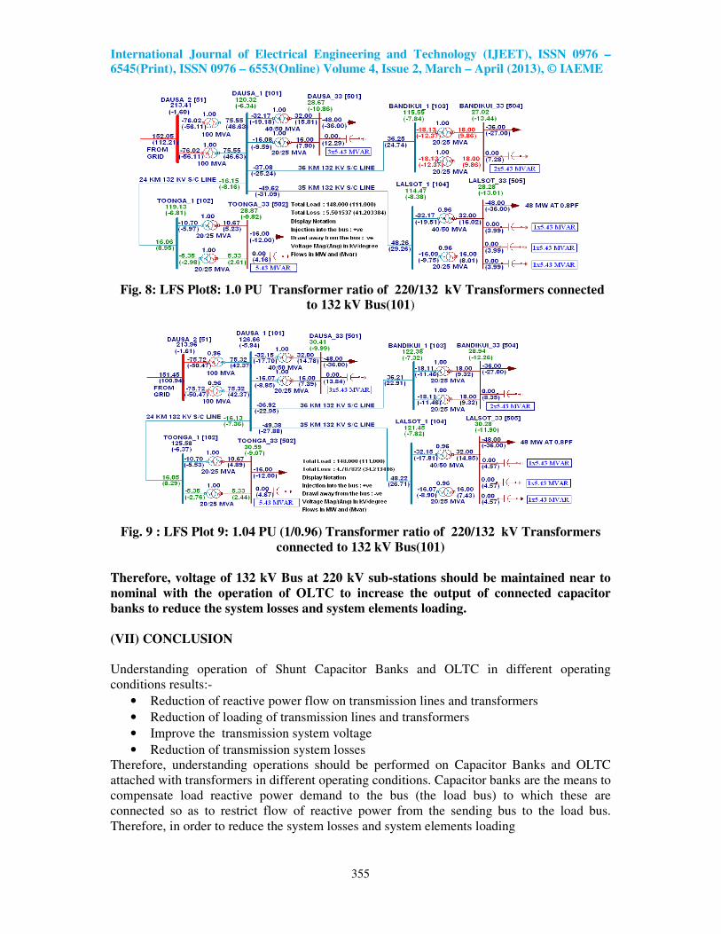
Power plots of LFS with total 148 MW, 0.80 PF load connected to 33 kV Buses No.
501, 502, 504 and 505 is placed at LFS plots-8. Under this condition
• Voltages of 33 kV buses is poor, therefore, output of capacitor banks is below to their
rated capacity
• Voltages of 132 kV buses is also poor
• Tap position of 220/132 kV transformers is 1.0 PU
Now transformer ratio of 220/132 kV transformers connected to 132 kV Bus (101) is
increased from 1.0 PU (Case-1) to 1.04 PU (1/0.96) (Case-2) while other system conditions
remain unchanged. Power plots of LFS with increase transformers ratio is placed at LFS
plots-9. Impact of rise in 220/132 kV transformer tap ratio on reactive power flow,
transmission losses, system voltage and system element loading have been analyzed.

International Journal of Electrical Engineering and Technology (IJEET), ISSN 0976 –
6545(Print), ISSN 0976 – 6553(Online) Volume 4, Issue 2, March – April (2013), © IAEME
354
• Impact on Reactive Power Flow
Reactive flow on Transformer
Ratio:1.00PU
Transformer
Ratio:1.04PU
Reactive power
injection by the
Connected
Capacitor banks at
various 33 Buses
35.97
MVAR
40.57 MVAR
220/132kV
Transformers
112.21 MVAR 100.94 MVAR
• Impact on voltage profile
Particulars Transformer
Ratio:1.0PU
Transformer
Ratio:1.04PU
132 kV bus voltage 126.66 kV 136.06 kV
220 kV bus voltage 213.41 kV 213.96 kV
• Impact on Transformers and transmission lines loading
Particulars Transformer
Ratio:1.00PU
Transformer
Ratio:1.04PU
220/132 kV
transformers
loading
188.97 MVA 182.00 MVA
• Impact on Transmission losses
Particulars Transformer
Ratio:1.00PU
(Case-1)
Transformer
Ratio:1.04PU
(Case-2)
Total losses in
132kV network
of 220 kV GSS
5.50 MW 4.78 MW
• Saving in transmission losses in 132kV network in Case-2 as compared to Case-1: 0.72 MW
• Saving in transmission losses in 220kV & above network in Case-2 as compared to Case-1:
= 2.5 x 0.72 MW = 1.80 MW
• Saving in total transmission losses in Case-2 as compared to Case-1: 2.52 MW
• Yearly Energy Saving in Case-2 as compared to Case-1 for four hours: 36.79 LUs
• Saving in terms of rupees: 36.79 x2.00 = Rs 73.58 lacs/annum
This study indicates that rise in transformer tap ratio
of 220/132 kV transformers under low voltage condition increase the output of the connected
capacitor banks which results:
• Decrease the reactive power flow on Transformers and Transmission lines
• Decrease the MVA loading on transformers & transmission lines.
• Increase the 33 kV, 132 kV & 220 kV voltages which may be already low in some system
conditions..
• Decrease the total system losses.
International Journal of Electrical Engineering and Technology (IJEET), ISSN 0976 –
6545(Print), ISSN 0976 – 6553(Online) Volume 4, Issue 2, March – April (2013), © IAEME
355
Fig. 8: LFS Plot8: 1.0 PU Transformer ratio of 220/132 kV Transformers connected
to 132 kV Bus(101)
Fig. 9 : LFS Plot 9: 1.04 PU (1/0.96) Transformer ratio of 220/132 kV Transformers
connected to 132 kV Bus(101)
Therefore, voltage of 132 kV Bus at 220 kV sub-stations should be maintained near to
nominal with the operation of OLTC to increase the output of connected capacitor
banks to reduce the system losses and system elements loading.
(VII) CONCLUSION
Understanding operation of Shunt Capacitor Banks and OLTC in different operating
conditions results:-
• Reduction of reactive power flow on transmission lines and transformers
• Reduction of loading of transmission lines and transformers
• Improve the transmission system voltage
• Reduction of transmission system losses
Therefore, understanding operations should be performed on Capacitor Banks and OLTC
attached with transformers in different operating conditions. Capacitor banks are the means to
compensate load reactive power demand to the bus (the load bus) to which these are
connected so as to restrict flow of reactive power from the sending bus to the load bus.
Therefore, in order to reduce the system losses and system elements loading

International Journal of Electrical Engineering and Technology (IJEET), ISSN 0976 –
6545(Print), ISSN 0976 – 6553(Online) Volume 4, Issue 2, March – April (2013), © IAEME
356
• Capacity of Capacitor Banks at load Buses should be comparable to Bus reactive Power
Demand
• The shunt capacitors are required to be kept ‘ON’ till the reactive component of the load
(which is generally inductive) is more than the reactive power injected by the shunt
capacitors i.e. power factor of the load bus is lagging.
• Output of the capacitor banks is squarely proportional to system voltage where capacitor
bank is connected therefore load bus voltage should be maintained near to nominal for
maximum utilization of connected capacitor banks.
REFERENCE
1. R.F. Cook, “Optimizing the application of Shunt Capacitor for Reactive Volt-Ampere
Control and Loss Reduction” IEEE Trans. On Power Delivery, Vol. 80, Aug. 1999,
pp:430-444
2. B. V. Vidhute, Dr. H. P. Inamdar, and S.A. Deokar, “Maximum Loss Reduction by
Optimal Placement of Capacitors on a Distribution System” Power India Conference,
2008, IEEE, pp: 1-3.
3. Bei Gou “Optimal Capacitor Placement for improving Power quality, Power
Engineering Society Summer Meeting, IEEE, 1999, PP-488-492.
4. H. Kim, S-K. You, “Voltage Profile Improvement by capacitor Placement and control in
unbalanced distribution Systems using GA”, IEEE power Engineering Society Summer
Meeting, 1999, Vol. 2, pp. 18-22.
5. J. B. V. SUBRAHMANYAM, “Optimal Capacitor Placement in Unbalanced Radial
Distribution Networks” Journal of Theoretical and Applied Information Technology,
Vol6. No1. (pp 106 - 115)
6. M. H. Shwehdi, A. Mantawi , S. Selim, A “Capacitor Placement In Distribution
Systems, A New Formulation”
7. IEEE Bolgona Power Tech. Conference, June 23-26, 2003 Chun Wang and Hao Zhong
Cheng, “Reactive power optimization by plant growth simulation algorithm,” IEEE
Trans. on Power Systems, Vol.23, No.1, pp. 119-126, Feb. 2008
8. Suresh Kamble, and Dr. Chandrashekhar Thorat, “Characterization of Voltage Sag Due
to Balanced and Unbalanced Faults in Distribution Systems”, International Journal of
Electrical Engineering & Technology (IJEET), Volume 3, Issue 1, 2012, pp. 197 - 209,
ISSN Print : 0976-6545, ISSN Online: 0976-6553.
9. Om Prakash Mahela and Sheesh Ram Ola, “Optimal Placement and Sizing of HT Shunt
Capacitors for Transmission Loss Minimization and Voltage Profile Improvement: The
Case of Rrvpnl Power Grid”, International Journal of Electrical Engineering &
Technology (IJEET), Volume 4, Issue 2, 2013, pp. 261 - 273, ISSN Print : 0976-6545,
ISSN Online: 0976-6553.
10. S.Neelima and Dr. P.S.Subramanyam, “Effect of Load Levels on Sizing and Location of
Capacitors in Distribution Systems”, International Journal of Electrical Engineering &
Technology (IJEET), Volume 3, Issue 3, 2012, pp. 31 - 42, ISSN Print : 0976-6545,
ISSN Online: 0976-6553.

International Journal of Electrical Engineering and Technology (IJEET), ISSN 0976 –
6545(Print), ISSN 0976 – 6553(Online) Volume 4, Issue 2, March – April (2013), © IAEME
357
BIOGRAPHIES
Dr. M. P. Sharma received the B.E. degree in Electrical Engineering
in 1996 Govt. Engineering College, Kota, Rajasthan and M.Tech
degree in Power Systems in 2001 and Ph.D. degree in 2009 from
Malaviya Regional Engineering College, Jaipur (Now name as MNIT).
He is presently working as Assistant Engineer, Rajasthan Rajya Vidhyut
Prasaran Nigam Ltd., Jaipur. He is involved in the system studies of
Rajasthan power system for development of power transmission system in Rajasthan and
planning of the power evacuation system for new power plants. His research interest
includes Reactive Power Optimization, Power System Stability, reduction of T&D losses and
protection of power system.
Sarfaraz Nawaz has received his B.E. degree from University of
Rajasthan and M.Tech. degree from MNIT, Jaipur. His research interests
include power systems and power electronics. He is currently an Associate
Professor of the Electrical Engg. Dept., Swami Keshvanand Institute of
Technology, Management and Gramothan (SKIT), Jaipur, Rajasthan.
Top Related