


Languages
Pages
Legal

Installation Instructions andHomeowner’s Manual
INSTALLER: DO NOT DISCARD THIS MANUAL - LEAVE FOR HOMEOWNER
WARNING!IF THE INFORMATION IN THISMANUAL IS NOT FOLLOWEDEXACTLY, A FIRE OR EXPLO-SION MAY RESULT CAUSINGPROPERTY DAMAGE, PERSONALINJURY OR LOSS OF LIFE.
FOR YOUR SAFETY
DO NOT STORE OR USEGASOLINE OR OTHERFLAMMABLE VAPORS ANDLIQUIDS IN THE VICINITY OFTHIS OR ANY OTHERAPPLIANCE.
PLEASE READ THIS MANUALBEFORE INSTALLING ANDUSING APPLIANCE
Installation and service mustbe performed by a qualifiedinstaller, service agency orthe gas supplier.
WHAT TO DO IF YOU SMELL GAS:• Do not try to light any appliance.• Do not touch any electric switch;• Do not use any phone in your
building.• Immediately call your gas supplier
from your neighbor's phone. Followthe gas suppliers instructions.
• If you cannot reach your gassupplier call the fire department.
INSTALLER/CONSUMERSAFETY INFORMATION
Chateau™Direct Vent DecorativeGas ApplianceModel: DVT38, DVT44
CERTIFIED
DESIGN
CERTIFIED
20006081 7/04 Rev.5
410 Admiral Blvd. • Mississauga, Ontario, Canada L5T 2N6 • 905-670-7777www.majesticproducts.com • www.vermontcastings.com
CFM Specialty Home Products

2
Vermont Castings, Majestic Products Chateau™
20006081
Please read the installation & operating instructions before using this appliance.Thank you and congratulations on your purchase of a Vermont Castings, Majestic Products fireplace.
IMPORTANT: Read all instructions and warnings carefully before starting installation.Failure to follow these instructions may result in a possible fire hazard and will void the warranty.
Table of Contents
Installation & Operating InstructionsImportant Curing/Burning Instructions ................................................................................3Locating Your Fireplace .....................................................................................................3Fireplace Dimensions .........................................................................................................4Clearance to Combustibles ................................................................................................5Mantels ..............................................................................................................................5Hearth ..............................................................................................................................5Framing & Finishing ...........................................................................................................6Final Finishing ....................................................................................................................7Gas Specifications .............................................................................................................7Gas Inlet and Manifold Pressures ......................................................................................7High Elevations ..................................................................................................................7Gas Line Installation ...........................................................................................................7Remote ON/OFF Switch ....................................................................................................8Electrical Junction Box .......................................................................................................8Electronic Gas Control Valve .............................................................................................8
General Venting InformationGeneral Venting .................................................................................................................9General Venting Information - Termination Location .......................................................10General Information Assembling Vent Pipes ...................................................................11SK8 Venting Pipes ...........................................................................................................11Horizontal Termination .....................................................................................................12Vertical Termination .........................................................................................................12Sidewall Applications .......................................................................................................12Use of the Restrictor Plates in Horizontal Venting Applications .......................................12Sidewall Installation ..........................................................................................................14Vertical Through-the-Roof Applications ...........................................................................15Use of Restrictor Plates for Vertical Venting Applications ................................................15Vertical Through-the-Roof Installation ..............................................................................17Chimney Components ......................................................................................................19
Operating InstructionsGlass Information .............................................................................................................20Window Frame Assembly Removal .................................................................................20Glass Cleaning .................................................................................................................20Restrictor Plate Installation ..............................................................................................20Ceramic Refractory Installation ........................................................................................21Log, Lava Rock and Ember Placement ............................................................................22Flame & Temperature Adjustment ...................................................................................24Flame Characteristics ......................................................................................................24Lighting and Operating Instructions (Standing Pilot Models) ...........................................25Lighting and Operating Instructions (Electronic Ignition Models) .....................................26Troubleshooting ...............................................................................................................27Fuel Conversion ...............................................................................................................29
MaintenanceCleaning the Standing Pilot Control System ....................................................................32Cleaning Electronic Ignition System.................................................................................32Battery Replacement for Ignitor Module ...........................................................................32
Replacement Parts .......................................................................................................................33Optional Accessories ..................................................................................................................36Warranty .......................................................................................................................................37

3
Vermont Castings, Majestic Products Chateau™
20006081
This appliance may be installed in an aftermarketpermanently located, manufactured home or mobilehome, where not prohibited by local codes.This appliance is only for use with the type of gasindicated on the rating plate. This appliance is notconvertible for use with other gases, unless a certifiedkit is used.The DVT38/44 has been approved for mobile homeinstallations.
This gas fireplace should be installed by a qualified installer inaccordance with local building codes and with current CSA-B149.1 Installation codes for Gas Burning Appliances andEquipment. For USA Installations follow local codes and/or thecurrent National Fuel Gas Code. ANSI Z223.1/NFPA 54.FOR SAFE INSTALLATION AND OPERATION PLEASENOTE THE FOLLOWING:1 . This fireplace gives off high temperatures and should be
located out of high traffic areas and away from furnitureand draperies.
2. Children and adults should be alerted to the hazards of thehigh surface temperatures of this fireplace and should stayaway to avoid burns or ignition of clothing.
3. CAUTION: Due to high glass surface temperaturechildren should be carefully supervised when in thesame room as fireplace.
4. Under no circumstances should this fireplace be modified.Parts removed for servicing should be replaced prior tooperating this fireplace again.
5. Installation and any repairs to this fireplace must beperformed by a qualified installer, service agency or gassupplier. A professional service person should be con-tacted to inspect the fireplace annually. More frequentcleaning may be required due to excess lint and dust fromcarpeting, bedding material, etc.
6. Control compartments, burners and air passages in thisfireplace should be kept clean and free of dust and lint.Make sure that the gas valve and pilot light are turned offbefore you attempt to clean this fireplace.
7. The venting system (chimney) of this fireplace should bechecked at least once a year and if needed your ventingsystem should be cleaned.
8. Keep the area around your fireplace clear of combustiblematerials, gasoline and other flammable vapor and liquids.This fireplace should not be used as a drying rack forclothing, nor should Christmas stockings or decorations behung on or around the fireplace.
9. Under no circumstances should any solid fuels (wood, coal,paper or cardboard etc.) be used in this fireplace.
10.The flow of combustion and ventilation air must not beobstructed in any way.
11.When the fireplace is installed directly on carpeting, vinyltile or any combustible material other than wood, thisfireplace must be installed on a metal or wood panelextending the full width and depth of the fireplace.
12.This fireplace requires adequate ventilation andcombustion air to operate properly.
13. This fireplace must not be connected to a chimney flueserving a separate solid fuel burning fireplace.
14. When the fireplace is not in use it is recommended that thegas control valve be left in the “OFF” position.
NOTE: This appliance uses a fast acting thermocoupleand must be replaced with same.
Installation & Operating Instructions
Proposition 65 Warning: Fuels used in gas,woodburning or oil fired appliances, and the products ofcombustion of such fuels, contain chemicals known tothe State of California to cause cancer, birth defectsand other reproductive harm.California Health & Safety Code Sec. 25249.6
IMPORTANT:PLEASE REVIEW THE FOLLOWING CAREFULLY
Remove any plastic from parts before turning thefireplace ON.It is normal for fireplaces fabricated of steel to give offsome expansion and/or contraction noises during thestart up or cool down cycle. Similar noises are foundwith your furnace heat exchanger or car engine.It is not unusual for your Vermont Castings, MajesticProducts gas fireplace to give off some odor the firsttime it is burned. This is due to the curing of the paintand any undetected oil from the manufacturing pro-cess.Please ensure that your room is well ventilated-open all windows.It is recommended that you burn your fireplace for atleast ten (10) hours the first time you use it.
Locating Your Fireplace
YE A B
C
D
F
Y B
X
LU584-1
Fig. 1 Locate gas fireplace.A)Flat on wall B)Cross corner C) **IslandD)*Room divider E)*Flat on wall corner F) Chase installationY) 6" minimum
Note (Fig. 1):** Island (C) and Room Divider (D) installation is possible aslong as the horizontal portion of the vent system (X) does notexceed 20 feet (610cm). See details in Venting Section.* When you install your Vermont Castings, Majestic Productsfireplace in (D) Room divider or (E) Flat on wall corner posi-tions (Y), a minimum of 6” (152mm) clearance must be main-tained from the perpendicular wall and the front side edge ofthe fireplace.

4
Vermont Castings, Majestic Products Chateau™
20006081
Rough Opening Width 49⁷⁄₈"(1267mm)Rough
OpeningHeight
RoughOpening
Depth
43⁷⁄₈" (1114mm)
40¹⁄₂" (1029 mm)
57⁵⁄₈" (1464mm)
81³⁄₈
" (20
67mm)
8³⁄₈" Dia.(213mm)
11" Dia.(279mm)
54⁷⁄₈"(1394mm)
10" (254mm)
3³⁄₈" (86mm)
38¹⁄₂"(978 mm)
2³⁄₈"(60mm)
34¹⁄₂"(875mm)
1⁵⁄₈"(41mm)
1/2" (13mm)
11³⁄₄"(298mm)
28¹⁄₂"(724mm)
25¹⁄₂"(648mm)
23¹⁄₈" (587mm)
3" (76mm)
57⁵⁄₈
" (14
64m
m)
41¹⁄₈
" (10
45mm)
3/4" (
19mm)
3/4" (19mm)
3" (7
6mm)
55"(1397mm)
9¹⁄₄"(235mm)
12¹⁄₄"(311mm)
5¹⁄₂"(140mm)
7³⁄₈"(187mm)
Fireplace Dimensions - DVT44
Fig. 3 Fireplace specifications and framing dimensions for the DVT44.
No drywall in this area, MUST use noncombustiblewallboard such as Dura Rock.
Valve box should not be left attached to the unit.
Rough Opening Width 43⁷⁄₈"(1114mm)
RoughOpeningHeight
RoughOpening
Depth
37⁷⁄₈" (962mm)
34¹⁄₂" (876mm)
54" (1372mm)
76³⁄₈" (
1940
mm)
8³⁄₈" Dia.(213mm)11" Dia.(279mm)
49¹⁄₂"(1257mm)
10" (254mm)
3³⁄₈" (86mm)
33³⁄₈"(848mm)
2³⁄₈"(60mm)
29³⁄₈"(746mm)
1⁵⁄₈"(41mm)
1/2" (13mm)
11³⁄₄"(298mm)
28¹⁄₂"(724mm)
25¹⁄₂"(648mm)
17" (432mm)
3" (76mm)
38¹⁄₈" (
968m
m)
3/4" (
19mm)
3/4" (19mm)
3" (7
6mm
)
55"(1397mm)
9¹⁄₄"(235mm)
12¹⁄₄"(311mm)
5¹⁄₂"(140mm)
7³⁄₈"(187mm)
54"
(137
2mm
)Fireplace Dimensions - DVT38
No drywall in this area, MUST use noncombustiblewallboard such as Dura Rock.
Valve box should not be left attached to the unit.
Fig. 2 Fireplace specifications and framing dimensions for DVT38.
5
Vermont Castings, Majestic Products Chateau™
20006081
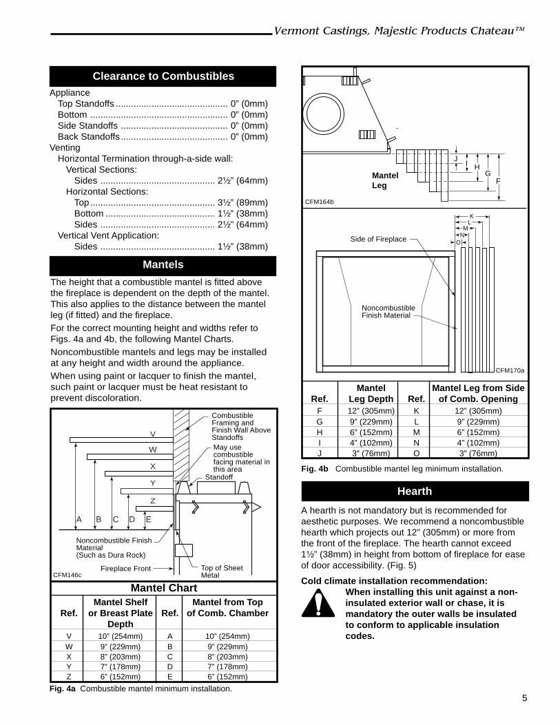
ApplianceTop Standoffs ............................................ 0” (0mm)Bottom ...................................................... 0” (0mm)Side Standoffs .......................................... 0” (0mm)Back Standoffs.......................................... 0” (0mm)
VentingHorizontal Termination through-a-side wall:
Vertical Sections:Sides ............................................. 2¹⁄₂” (64mm)
Horizontal Sections:Top ................................................. 3¹⁄₂” (89mm)Bottom ........................................... 1¹⁄₂” (38mm)Sides ............................................. 2¹⁄₂” (64mm)
Vertical Vent Application:Sides ............................................. 1¹⁄₂” (38mm)
A hearth is not mandatory but is recommended foraesthetic purposes. We recommend a noncombustiblehearth which projects out 12” (305mm) or more fromthe front of the fireplace. The hearth cannot exceed1¹⁄₂” (38mm) in height from bottom of fireplace for easeof door accessibility. (Fig. 5)
Cold climate installation recommendation:When installing this unit against a non-insulated exterior wall or chase, it ismandatory the outer walls be insulatedto conform to applicable insulationcodes.
Hearth
Mantels
The height that a combustible mantel is fitted abovethe fireplace is dependent on the depth of the mantel.This also applies to the distance between the mantelleg (if fitted) and the fireplace.For the correct mounting height and widths refer toFigs. 4a and 4b, the following Mantel Charts.Noncombustible mantels and legs may be installedat any height and width around the appliance.When using paint or lacquer to finish the mantel,such paint or lacquer must be heat resistant toprevent discoloration.
Clearance to Combustibles
Fig. 4a Combustible mantel minimum installation.
A B C D E
V
W
X
Y
Z
Mantel ChartMantel Shelf Mantel from Top
Ref. or Breast Plate Ref. of Comb. ChamberDepth
V 10” (254mm) A 10” (254mm)W 9” (229mm) B 9” (229mm)X 8” (203mm) C 8” (203mm)Y 7” (178mm) D 7” (178mm)Z 6” (152mm) E 6” (152mm)
CFM146c
CombustibleFraming andFinish Wall AboveStandoffs
Standoff
Top of SheetMetal
Noncombustible FinishMaterial(Such as Dura Rock)
Fireplace Front
May usecombustiblefacing material inthis area
J
FG
HI
MantelLeg
CFM164b
ONM
LK
CFM170a
Fig. 4b Combustible mantel leg minimum installation.
Mantel Mantel Leg from SideRef. Leg Depth Ref. of Comb. Opening
F 12” (305mm) K 12” (305mm)G 9” (229mm) L 9” (229mm)H 6” (152mm) M 6” (152mm)I 4” (102mm) N 4” (102mm)J 3” (76mm) O 3” (76mm)
Side of Fireplace
NoncombustibleFinish Material

6
Vermont Castings, Majestic Products Chateau™
20006081
Framing and Finishing
NOTE: The valve box assembly must be installed inthe same room as the fireplace.1. Choose the unit location.2. The unit is shipped with four (4) nailing flanges
mounted to the sides near the front corners. (Fig. 5)3. Frame the fireplace with a header across the top of
the standoff. (Fig. 6) It is very important to allow forthe finished wall face along with marble, tiles or any
other noncombustible face finish material desiredwhen setting the depth of the framing.
4. Attach the fireplace nailing flanges to the frame asshown in Figure 5.
5. The gas components are located in the controlpanel assembly attached to the right side of theunit. Choose the desired location on the wall ormantel for the valve box assembly. The conduitlength is 5’ (1524mm). (Fig. 7) The framing dimen-sions for the box are 12¹⁄₄”L x 9¹⁄₄”W x 5⁵⁄₈”D(311mm x 235mm x 143mm). When the framing forthe box is complete, remove the screws securingthe valve box to the outer casing. Carefully removethe valve box and, without stressing the conduit,slide the box into the framed opening. Replace thescrews removed from the side of the outer casing.
3"(76mm) Min.
3"(76mm) Min.
1¹⁄₂"(38mm)
Max. Hearth Height FP1357
Fig. 5 Nailing flanges.
BendLine
FP1361
Fig. 7 Valve box assembly location.
53"
(134
6mm
)
45" (1143mm)
Fig. 6 Fireplace framing.
FP13583"
(76mm)
3"(76mm)
6. To secure the valve box assembly to the framingmembers, open the box door, remove extensionknob(s). For units with two piece cover plates,remove the front cover plate by removing thescrews holding the front plate to the second plate.Disconnect the wires for the pilot indicator andremove the second plate located at the top of thebox.For units with a one piece cover plate, remove thevalve cover by removing the two (2) screws secur-ing the valve cover to the box, hold the cover platewith one hand and disconnect the wires to theswitch and pilot indicator (R models only). NOTE:Do not allow the valve cover plate to hang from thepilot indicator wires as this could damage the wires.Secure the box to the framing through the two (2)holes at the top and one (1) on each side usingsheet rock screws. (Fig. 8) After framing the box,replace the wires, the valve cover, the extensionknob(s) in reverse order.NOTE: The pilot indicator body is labelled +/-, makesure the positive wire on the pilot indicator goes toground and the negative goes to the plug betweenthe valve and the thermocouple.

7
Vermont Castings, Majestic Products Chateau™
20006081
9¹⁄₄" (235mm)
12¹⁄₄"(311mm)
FP1362
Fig. 8 Valve box framing.7. The U-channel located on the top of the unit as well
as the nailing flanges on the sides that were men-tioned in Step 1, are designed to accommodatenoncombustible board (recommended Dura-Rock).They are positioned 1” (25mm) back from the faceof the unit. NOTE: The U-channel depth can beadjusted by loosening the hex nut inside the chan-nel.If marble, tile or any other noncombustible decora-tive face finish material is desired, a 3” (76mm) widenoncombustible board (recommended Dura-Rock)is to be nailed to the nailing flanges on both sides ofthe unit. Also, 12” (305mm) of noncombustibleboard is to be nailed to the front face of the U-channel and the top framing member above thestandoff.Combustible material can then be brought to theoutside edges of the noncombustible board installedearlier. Any noncombustible decorative face finishcould be brought to the sides and top of the unit andcan cover the framing and sheet rock. If a decora-tive facing is not desired, then the noncombustibleboards must be double thickness and brought flushwith the face of the unit.
Gas Inlet and Manifold Pressures
Natural LP (Propane)Minimum Inlet Pressure 5.5” w.c. 11.0” w.c.Maximum Inlet Pressure 14.0” w.c. 14.0” w.c.Manifold Pressure 3.5” w.c. 10.0” w.c.
Final Finishing
Noncombustible materials such as brick or tile may bebrought to the edges of the face of the appliance.
Gas Specifications
MAX. MIN.GAS INPUT INPUT
MODEL FUEL CONTROL B.T.U.H B.T.U.H.DVT38RN Natural Gas Millivolt 46,000 34,000DVT38RP Propane Millivolt 46,000 36,000DVT38EN Natural Gas 24V Hi/Lo 46,000 34,000DVT38EP Propane 24V Hi/Lo 46,000 36,000DVT44RN Natural Gas Millivolt 60,000 37,000DVT44RP Propane Millivolt 60,000 45,000DVT44EN Natural Gas 24V Hi/Lo 60,000 37,000DVT44EP Propane 24V Hi/Lo 60,000 45,000
DVT38 / DVT44Certified To
ANSI Z21.50b-2002/CSA 2.22b-2002Vented Gas Fireplace
High Elevations
Input ratings are shown in BTU per hour and arecertified without deration for elevations up to4,500 feet (1,370m) above sea level.
For elevations above 4,500 feet (1,370m) in USA,installations must be in accordance with thecurrent ANSI Z223.1/NFPA 54 and/or local codeshaving jurisdiction.
In Canada, please consult provincial and/or localauthorities having jurisdiction for installations atelevations above 4,500 feet (1,370m).
WARNING: Improper installation, adjust-ment, alteration, service or maintenance cancause injury or property damage. Refer tothis manual for correct installation andoperational procedures. For assistance oradditional information consult a qualifiedinstaller, service agency, or the gas supplier.
Gas Line Installation
When purging gas line the front glassmust be removed.
A gas shut off valve must be installed onthe gas pipe line going into the appliancewithin easy access.
The gas pipeline can be brought in through the bottomright side of the valve box assembly.The gas line connection can be made with properlytinned 1/2" copper tubing or 1/2” gas tight. Somemunicipalities have additional local codes, it is alwaysbest to consult your local authority and the CSA-B149.1installation codes.For USA installations consult the current National FuelGas Code, ANSI Z223.1/NFPA 54.
8
Vermont Castings, Majestic Products Chateau™
20006081
The fireplace, when installed, must beelectrically connected and grounded inaccordance with local codes or, in theabsence of local codes, with the currentCSA C22.1 Canadian Electrical Code orthe national electrical code ANSI/NFPANo. 70 in the USA.
It is strongly suggested that the wiring ofthe Electrical Junction Box be carriedout by a licensed electrician. The boxshould be near the valve box assemblyto plug the cord into.
Ensure the power to the supply line hasbeen disconnected before commencingthis procedure.
Electrical Junction Box (E Units Only)
Do not wire the remote ON/OFF wallswitch for this gas appliance into a 120Vpower supply.
The unit is equipped with an ON/OFF rocker switch atthe valve box assembly. If a wall switch is desired,follow these instructions.1. The valve box is equipped with two knockouts at the
top right and left corners. The right knockout isdesigned to run the wall switch wires to the valve.Use Romex connectors when running wires throughthe valve box where the knockouts are located.
2. Attach the wire to the ON/OFF switch and install theswitch into the receptacle box.
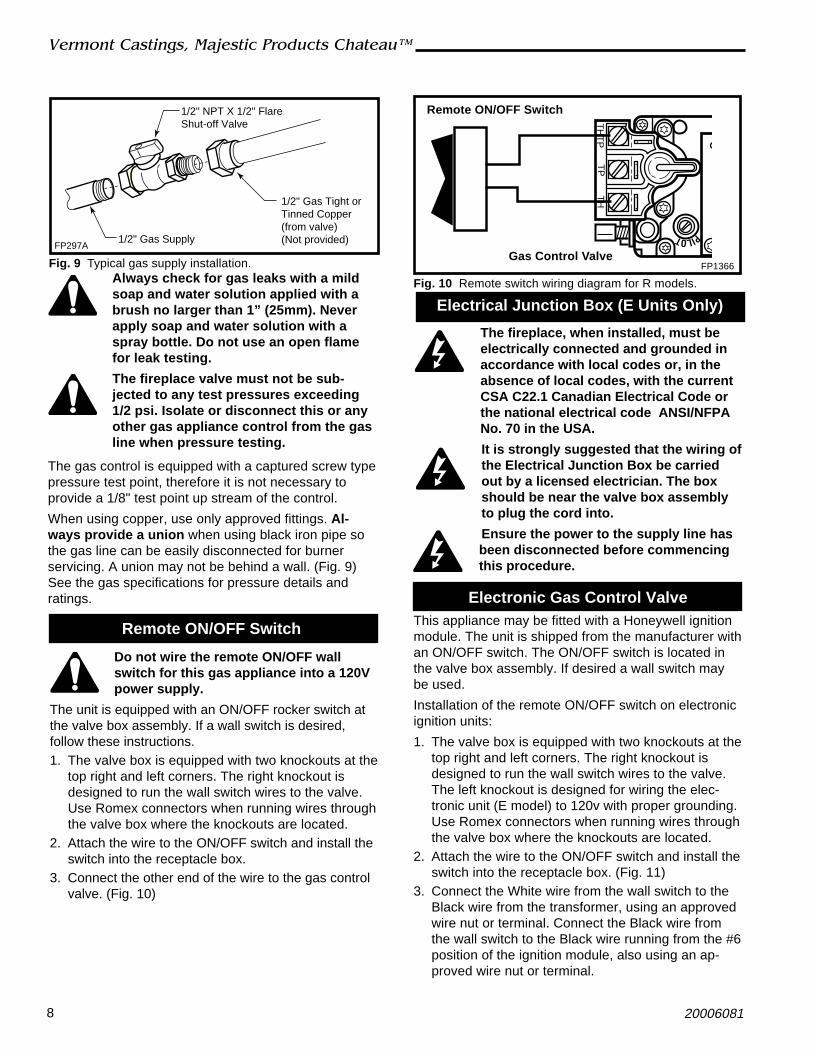
3. Connect the other end of the wire to the gas controlvalve. (Fig. 10)
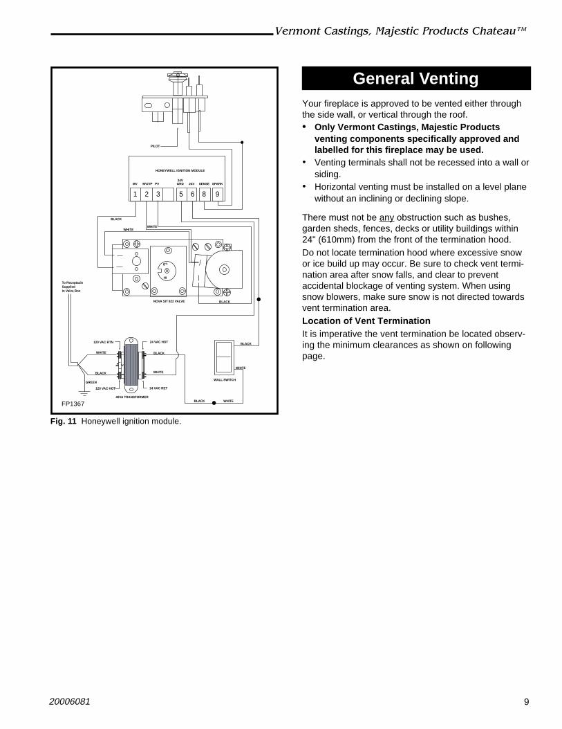
Remote ON/OFF Switch This appliance may be fitted with a Honeywell ignitionmodule. The unit is shipped from the manufacturer withan ON/OFF switch. The ON/OFF switch is located inthe valve box assembly. If desired a wall switch maybe used.
Installation of the remote ON/OFF switch on electronicignition units:
1. The valve box is equipped with two knockouts at thetop right and left corners. The right knockout isdesigned to run the wall switch wires to the valve.The left knockout is designed for wiring the elec-tronic unit (E model) to 120v with proper grounding.Use Romex connectors when running wires throughthe valve box where the knockouts are located.
2. Attach the wire to the ON/OFF switch and install theswitch into the receptacle box. (Fig. 11)
3. Connect the White wire from the wall switch to theBlack wire from the transformer, using an approvedwire nut or terminal. Connect the Black wire fromthe wall switch to the Black wire running from the #6position of the ignition module, also using an ap-proved wire nut or terminal.
Electronic Gas Control Valve
Always check for gas leaks with a mildsoap and water solution applied with abrush no larger than 1” (25mm). Neverapply soap and water solution with aspray bottle. Do not use an open flamefor leak testing.
The fireplace valve must not be sub-jected to any test pressures exceeding1/2 psi. Isolate or disconnect this or anyother gas appliance control from the gasline when pressure testing.
The gas control is equipped with a captured screw typepressure test point, therefore it is not necessary toprovide a 1/8" test point up stream of the control.
When using copper, use only approved fittings. Al-ways provide a union when using black iron pipe sothe gas line can be easily disconnected for burnerservicing. A union may not be behind a wall. (Fig. 9)See the gas specifications for pressure details andratings.
FP297A1/2" Gas Supply
1/2" NPT X 1/2" FlareShut-off Valve
1/2" Gas Tight orTinned Copper(from valve)(Not provided)
Fig. 9 Typical gas supply installation.
PILOT
TH
TP
TP
TH
Fig. 10 Remote switch wiring diagram for R models.
Remote ON/OFF Switch
Gas Control ValveFP1366
9
Vermont Castings, Majestic Products Chateau™
20006081
General VentingYour fireplace is approved to be vented either throughthe side wall, or vertical through the roof.• Only Vermont Castings, Majestic Products
venting components specifically approved andlabelled for this fireplace may be used.
• Venting terminals shall not be recessed into a wall orsiding.
• Horizontal venting must be installed on a level planewithout an inclining or declining slope.
There must not be any obstruction such as bushes,garden sheds, fences, decks or utility buildings within24" (610mm) from the front of the termination hood.Do not locate termination hood where excessive snowor ice build up may occur. Be sure to check vent termi-nation area after snow falls, and clear to preventaccidental blockage of venting system. When usingsnow blowers, make sure snow is not directed towardsvent termination area.Location of Vent TerminationIt is imperative the vent termination be located observ-ing the minimum clearances as shown on followingpage.
PILOT
HONEYWELL IGNITION MODULE
WHITE
BLACK
BLACK
NOVA SIT 822 VALVE
HI
LO
120 VAC RTN
WHITE
GREEN
BLACK
120 VAC HOT
BLACK
WHITE
24 VAC RET
40VA TRANSFORMER
24 VAC HOT
BLACK WHITE
WALL SWITCH
WHITE
1 2 3 5 6 8 9
MV MV/VP PV GRD 24V SENSE SPARK24V
WHITE
BLACK
To Receptacle Suppliedin Valve Box
FP1367
Fig. 11 Honeywell ignition module.

10
Vermont Castings, Majestic Products Chateau™
20006081
V
V
V
V
V
V
V
X
X
X
D
E
B
B B
C
BM
B
A
JK
F
L
VENT TERMINATION AIR SUPPLY INLET AREA WHERE TERMINAL IS NOT PERMITTED
H
I
FixedClosedFixed
Closed
OperableOperable Fixed
Closed
VB
INSIDECORNER DETAIL
V
A
G
V
NN
V
V
G
G
A
CFM145a
General Venting Information - Termination Location
A = Clearance above grade, veranda, porch, 12” (30cm) 12” (30cm)deck, or balcony
B = Clearance to window or door that may be 6” (15cm) for appliances 6” (15cm) for appliancesopened < 10,000Btuh (3kW), 12” (30cm) < 10,000 Btuh (3kW), 9”
for appliances > 10,000 Btuh (3kW) and (23cm) for appliances > 10,000< 100,000 Btuh (30kW), 36” (91cm) Btuh (3kW) and < 50,000 Btuhfor appliances > 100,000 Btuh (30kW) (15kW), 12” (30cm) for
appliances > 50,000 Btuh (15kW)C = Clearance to permanently closed window 12” (305mm) recommended to 12” (305mm) recommended to
prevent window condensation prevent window condensationD = Vertical clearance to ventilated soffit located
above the terminal within a horizontal 18” (458mm) 18” (458mm)distance of 2 feet (610mm) from the centerline of the terminal
E = Clearance to unventilated soffit 12” (305mm) 12” (305mm)F = Clearance to outside corner see next page see next pageG = Clearance to inside corner (see next page) see next page see next pageH = Clearance to each inside of center line 3’ (91cm) within a height of 15’ 3’ (91cm) within a height of 15’
extended above meter/regulator assembly above the meter/regulator assembly above the meter/regulator assyI = Clearance to service regulator vent outlet 3’ (91cm) 3’ (91cm)J = Clearance to nonmechanical air supply inlet 6” (15cm) for appliances < 10,000 6” (15cm) for appliances
to building or the combustion air inlet to any Btuh (3kW), 12” (30cm) for < 10,000 Btuh (3kW), 9”other appliances appliances > 10,000 Btuh (3kW) and < (23cm) for appliances > 10,000
100,000 Btuh (30kW), 36” (91cm) Btuh (3kW) and < 50,000 Btuhfor appliances > 100,000 Btuh (30kW) (15kW), 12” (30cm) for
appliances > 50,000 Btuh (15kW)K = Clearance to a mechanical air supply inlet 6’ (1.83m) 3’ (91cm) above if within 10’
(3m) horizontallyL = Clearance above paved sidewalk or paved 7’ (2.13m)† 7’ (2.13m)†
driveway located on public propertyM = Clearance under veranda, porch, deck or 12” (30cm)‡ 12” (30cm)‡
balconyN = Clearance above a roof shall extend a minimum of 24” (610mm) above the highest point when it passes through the roof
surface, and any other obstruction within a horizontal distance of 18” (450mm).1 In accordance with the current CSA-B149 Installation Codes2 In accordance with the current ANSI Z223.1/NFPA 54 National Fuel Gas Codes† A vent shall not terminate directly above a sidewalk or paved driveway which is located between two single family dwellings and
serves both dwellings‡ only permitted if veranda, porch, deck or balcony is fully open on a minimum 2 sides beneath the floor:NOTE: 1. Local codes or regulations may require different clearances.
2. The special venting system used on Vermont Castings, Majestic Products Direct Vent Fireplaces are certified as part of theappliance, with clearances tested and approved by the listing agency.
Canadian Installations1 US Installations2
Fig. 12 Vent termination clearances.
*Clearances to soffit do not apply to “vinyl soffits”.

11
Vermont Castings, Majestic Products Chateau™
20006081
584-15
Outside CornerInside Corner
Termination ClearancesTermination clearances for buildings with combustible and noncombustible exteriors.
A =Combustible 6"(152mm)Noncombustible 2"(50mm)
B =Combustible 6"(152mm)Noncombustible 2"(50mm)
A
Balcony - with no side wall
G = Combustible &Noncombustible 12"(305mm)
G
Balcony - with perpendicular side wall
H = 24"(610mm)
J = 20"(508mm)
H
J
B
Recessed Location
C = Maximum depth of 48" (1219mm) for recessed location. D = Minimum width for back wall of a recessed location. Combustible 38"(965mm) Noncombustible 24"(610mm)
E = Clearance from corner in recessed location. Combustible 6"(152mm) Noncombustible 2"(50mm)
CD
CE
V
V
Combustible &Noncombustible
V V
V
Fig. 13 Termination clearances.
General Information Assembling Vent Pipes
SK8 Venting Pipes
Canadian Installations:The venting system must be installed in accordancewith the current CSA-B149 .1 installation code.USA Installations:The venting system must conform with local codesand/or the current National Fuel Gas code ANSIZ223.1/NFPA 54.Only venting components manufactured by VermontCastings, Majestic Products can be used in Direct Ventsystems.NOTE: The joints of the inner pipe (flue pipe) must betaped with 550°F or higher temperature metal adhesivetape that meets the requirements of F.A.R. 25.853(a)High temperature sealant milpack or stove cement of550°F or higher could be used instead. The joints ofThe outer pipe (fresh air pipe) must be taped with315°F or higher temperature metal adhesive tape orthe use of high temperature milpack or stove cementwould be applicable. When using the unitized 30°, 45°
or 90° elbows, apply 1/4” bead of high temperature,550°F or higher, sealant (milpack or stove cement) tothe joint of the inner pipe (flue pipe) and the straightsection as it is impossible to be taped. The outer pipemust be taped with 315°F high temperature metaladhesive tape for proper sealing.Start by attaching the first vent pipe section to thecollar on top of the fireplace. In order to attach the firstpipe section, it may be necessary to remove the topshield. Remove four (4) screws securing top shield,install first pipe section and replace top shield.Install the pipe as shown in Figure 14. When you get agood lock, you will hear the pipe clearly snap together.Once sections are snap-locked in place, it is extremelydifficult to get them apart. Make sure the pipe is firmlysnapped and locked together as each pipe section ismounted.When installing elbows, follow the same procedure.The joints of inner and outer elbow must be taped withUL approved high temperature metal adhesive tape for

12
Vermont Castings, Majestic Products Chateau™
20006081
Sidewall Applications
Horizontal Termination
The vent must rise vertically a minimum of 24”(610mm) off the top of the unit, before the first elbow.The horizontal run may extend up to 20’ (6m) andinclude a vertical rise of up to 40’ (12m). (Fig. 15)Horizontal termination must also meet the criteriashown in Figures 12 & 13.
• Approved vent systems must terminate above andincluding the heavy line in Figure 15.
• Two 45° elbows may be substituted for each single90° elbow.
• With a rise between 2’ - 4’, one (1) 90° or two (2)45° elbows may be used.
20
19
18
16
15
14
13
12
11
10
9
8
7
6
5
4
3
2
1
0
1 2 3 4 5 6 7 8 9 10 11 12 13 14 15 16 17 18 19 20
Ver
tica
l Ru
n (
in f
eet)
(Mea
sure
d f
rom
th
e ap
plia
nce
flu
e co
llar
to t
he
top
of
the
ven
t p
ipe.
)
Horizontal Run (in feet)
21
22
2324
25
26
27
28
29
30
31
32
33
34
35
36
37
38
39
40
May use up tothree (3) 90°
elbows, but mustnot have two (2)consecutive 90°
elbows inhorizontal plane
Unacceptableventing configuration
FP1359
Fig. 15 Horizontal vent termination window.
May useone (1)elbowonly
UP
Pipe Section
PipeRim
PipeRim
Hem
Lance
FP1368
Fig. 14 Install pipe, listening for the snap-lock to fasten.
proper sealing. Be sure to always attach straps onupper elbow to a structural framing member.For vertical installations, continue installing the pipe asrequired until pipe is installed up through the ceiling. Atthis point, you must install a firestop spacer.
Vertical Termination
A vertical vent system must terminate no less than 12’(3.66m) and no more than 40’ (12m) above the appli-ance flue collar. A 2’ (610mm) vertical section must beinstalled before any offset. A maximum of 20’ (6.1m)horizontal and three (3) 90° elbows may be installedwith a minimum of 12’ (3.66m) vertical section abovethe flue collar of the unit. Refer to Page 15, Figure 26for more information.
A vertically terminated vent system must also conformto the following criteria:
• No more than three (3) 90° elbows may be used.• Two (2) 45° elbows may be substituted for one (1)
90° elbow. No more than six (6) elbows may beused.
• Vent must rise a minimum of 2’ (610mm) beforeoffset is used.
• Termination height must conform to roof clearanceas specified in Figure 34.
Since it is very important that the ventingsystem maintain its balance between thecombustion air intake and the flue gasexhaust, certain limitations as to ventconfigurations apply and must be strictlyadhered to.
Use of the Restrictor Plates inHorizontal Venting Applications
The primary purpose for the vent restrictor plate is toregain flame height under certain venting conditions asoutlined below.

13
Vermont Castings, Majestic Products Chateau™
20006081
DVT44 ONLY
When using the horizontal starter vent kit, SK8DVSK,with natural gas, do not use the restrictor plate. If usingthis vent kit with liquid propane, the 4¹⁄₂” restrictor platemay be used. (Fig. 16)
24"(610mm)
Min.
12"(305mm)
Min.
LP Only Use 4¹⁄₂"
FP1408
Fig. 16 Restrictor plate in horizontal venting.
For propane unit, fresh air restrictor plate is shippedfrom the factory at the #2 setting and can be adjustedto setting #1 in some applications if needed. Refer toPages 20 & 21, Figures 36 & 38 for restrictor plateinstallation and fresh air plate setting adjustment.
DVT38 ONLY
When using the horizontal starter vent kit, SK8DVSK,with liquid propane, do not use the restrictor plate. Ifusing this vent kit with natural gas, the 3” restrictor platemay be used. (Fig. 16)
The vent graph showing the relationship betweenvertical and horizontal side wall venting will help todetermine the various dimensions allowable.
Minimum clearance between vent pipesand combustible materials is 3¹⁄₂” (89mm)on top, 2¹⁄₂” (64mm) on both sides and1¹⁄₂” (38mm) on the bottom.
When the vent termination exits through foundationsless than 20” (508mm) below siding outcrop, the ventpipe must be flush with the siding.
It is always best to locate the fireplace in such a waythat minimizes the number of offsets and horizontalvent length of vent pipe from the flue collar of thefireplace to the face of the outer wall.Horizontal plane means no vertical rise exists on thisportion of the vent assembly.
• The maximum number of 90° elbows per side wallinstallation is three (3), but must not have two (2)consecutive elbows in the horizontal plane.
NOTE: Apply high temperature sealant or UL approvedhigh temperature metal adhesive tape as directed onPage 11.
14’ (
4.3m
)
Pipe StrapsEvery 3’(914mm) Firestop/Zero
Clearance Sleeve
PipeStrapsEvery 3’(914mm)
20’ (6m)
FP1012a
Fig. 17 Support straps for horizontal runs.
Minimum 2’(610mm) Section
Unitized Elbow(SK890)
• A minimum of 2’ (610mm) vertical section off the topof the unit is required, an elbow and a 1’ (305mm)maximum horizontal run to get through a wall. (Fig.18)
• The maximum number of 45° elbows permitted perside wall installation is two (2). These elbows can beinstalled in either the vertical or horizontal run. (Fig.19)
10’(3m)
AB
A + B = 17’ (5.2m)
FP1238
Fig. 19 Maximum vent run with elbows.
2’(610mm)
2’(610mm)
CL
X
FP1237a
Fig. 18 Minimum vertical run / maximum horizontal run.
WallOpening
(DVT44) X = 7’3¹⁄₄” (2216mm)(DVT38) X = 6’9⁷⁄₈” (2080mm)

14
Vermont Castings, Majestic Products Chateau™
20006081
Vent Opening for Combustible Wall16¹⁄₄”
(413mm)
Fireplace Hearth
FramingDetail
Vent Opening for Noncombustible Wall
11¹⁄₄”(286mm)
VO584-100
Fig. 21 Locate vent opening on wall.
16¹⁄₄”(413mm)
Adjustable ZeroClearance Sleeve Max. Length
12” (305mm)
#8 Screws (2)
#8 Screws (2)
ZCS101a
Fig. 22 Adjustable zero clearance sleeve.
STEP 1
Locate vent opening on the wall. It may be necessary tofirst position the fireplace and measure to obtain holelocation. Depending on whether the wall is combustibleor noncombustible, cut opening to size. (Fig. 21)
For combustible walls first frame in opening.
Combustible Walls: Cut a 16¹⁄₄”H x 16¹⁄₄” W (413mm x413mm) hole through the exterior wall and frame asshown.
Noncombustible Walls: Hole opening must be 11¹⁄₄”(286mm) in diameter.
STEP 2
Measure wall thickness and cut zero clearance sleeveparts to proper length (MAXIMUM 12”/305 mm).Assemble sleeve using #8 sheet metal screws (sup-plied). (Fig. 22) Install firestop assembly. (Fig. 31)
Zero clearance sleeve is only required forcombustible walls.
STEP 3
Slide the zero clearance sleeve through the wall andinstall the firestop on the inside surface of the wall.Secure with four (4) #8 sheet metal screws.
Sidewall Installation
X
FP1240a
Fig. 23 Vertical height requirement.
Firestop
ZeroClearanceSleeve
12
3
4Example: In Figure 23
Elbow 1 = 90°Elbow 2 = 45°Elbow 3 = 45°Elbow 4 = 90°
Total angular variation = 270°
FP1239a
Fig. 20 Maximum number of elbow degrees.
• For each 45° elbow installed in the horizontal run,the length of the horizontal run MUST be reduced by18” (45cm). This does not apply if the 45° elbowsare installed on the vertical part of the vent system.For each 90° elbow installed in the horizontal run,the length of the horizontal run MUST be reduced by36” (91cm).
• The maximum number of elbow degrees in a systemis 270°. (Fig. 20)
STEP 4
Place fireplace into position. (Fig. 23) Measure thevertical height (X) required from the base of the fluecollars to the center of the wall opening. NOTE: If usingthe SK8DVSK Kit, the vertical section of pipe is tel-escopic and could provide adjustment from 24” up to40” (610mm to 1016mm).
15
Vermont Castings, Majestic Products Chateau™
20006081
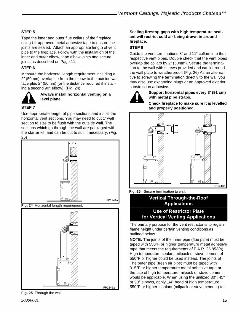
STEP 5
Tape the inner and outer flue collars of the fireplaceusing UL approved metal adhesive tape to ensure thejoints are sealed. Attach an appropriate length of ventpipe to the fireplace. Follow with the installation of theinner and outer elbow, tape elbow joints and securejoints as described on Page 11.
STEP 6
Measure the horizontal length requirement including a2” (50mm) overlap, ie from the elbow to the outside wallface plus 2” (50mm) (or the distance required if install-ing a second 90° elbow). (Fig. 24)
Always install horizontal venting on alevel plane.
STEP 7
Use appropriate length of pipe sections and install thehorizontal vent sections. You may need to cut 1’ wallsection to size to be flush with the outside wall. Thesections which go through the wall are packaged withthe starter kit, and can be cut to suit if necessary. (Fig.25)
X
FP1241a
Fig. 24 Horizontal length requirement.
FP1242a
Fig. 25 Through the wall.
Sealing firestop gaps with high temperature seal-ant will restrict cold air being drawn in aroundfireplace.
STEP 8
Guide the vent terminations 8” and 11” collars into theirrespective vent pipes. Double check that the vent pipesoverlap the collars by 2” (50mm). Secure the termina-tion to the wall with screws provided and caulk aroundthe wall plate to weatherproof. (Fig. 26) As an alterna-tive to screwing the termination directly to the wall youmay also use expanding plugs or an approved exteriorconstruction adhesive.
Support horizontal pipes every 3’ (91 cm)with metal pipe straps.
Check fireplace to make sure it is levelledand properly positioned.
FP1243a
Fig. 26 Secure termination to wall.
Use of Restrictor Platefor Vertical Venting Applications
The primary purpose for the vent restrictor is to regainflame height under certain venting conditions asoutlined below.NOTE: The joints of the inner pipe (flue pipe) must betaped with 550°F or higher temperature metal adhesivetape that meets the requirements of F.A.R. 25.853(a)High temperature sealant milpack or stove cement of550°F or higher could be used instead. The joints ofThe outer pipe (fresh air pipe) must be taped with315°F or higher temperature metal adhesive tape orthe use of high temperature milpack or stove cementwould be applicable. When using the unitized 30°, 45°or 90° elbows, apply 1/4” bead of high temperature,550°F or higher, sealant (milpack or stove cement) to
Vertical Through-the-RoofApplications
16
Vermont Castings, Majestic Products Chateau™
20006081
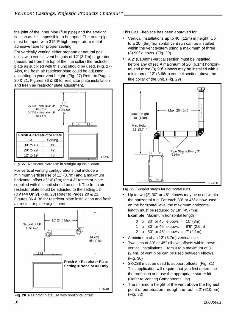
Max. 20’ (6m)Max. Height
40’ (12m)
Min. Height12’ (3.7m)
Pipe Straps Every 3’(914mm)
FP1244a
Fig. 29 Support straps for horizontal runs.
12’(3.7m)
Min. Rise
10’ (3m) Max.Natural or LP
Use 4¹⁄₂"
Fresh Air Restrictor PlateSetting = None or #3 Only
FP1410
Fig. 28 Restrictor plate use with horizontal offset.
the joint of the inner pipe (flue pipe) and the straightsection as it is impossible to be taped. The outer pipemust be taped with 315°F high temperature metaladhesive tape for proper sealing.For vertically venting either propane or natural gasunits, with vertical vent heights of 12’ (3.7m) or greater,(measured from the top of the flue collar) the restrictorplate as supplied with this unit should be used. (Fig. 27)Also, the fresh air restrictor plate could be adjustedaccording to your vent height. (Fig. 27) Refer to Pages20 & 21, Figures 36 & 38 for restrictor plate installationand fresh air restrictor plate adjustment.
For vertical venting configurations that include aminimum vertical rise of 12’ (3.7m) and a maximumhorizontal offset of 10’ (3m) the 4¹⁄₂” restrictor platesupplied with this unit should be used. The fresh airrestrictor plate could be adjusted to the setting #3(DVT44 Only). (Fig. 28) Refer to Pages 20 & 21,Figures 36 & 38 for restrictor plate installation and freshair restrictor plate adjustment.
12’(3.7m)
or Greater’X’
DVT44 - Natural or LPUse 6³⁄₄"
DVT38 - Natural or LPUse 5¹⁄₄"
FP1409
Fig. 27 Restrictor plate use in straight up installation.
Fresh Air Restrictor PlateX Setting
30’ to 40’ #120’ to 29’ #212’ to 19’ #3
This Gas Fireplace has been approved for,
• Vertical installations up to 40’ (12m) in height. Upto a 20’ (6m) horizontal vent run can be installedwithin the vent system using a maximum of three(3) 90° elbows. (Fig. 29)
• A 2’ (610mm) vertical section must be installedbefore any offset. A maximum of 20’ (6.1m) horizon-tal and three (3) 90° elbows may be installed with aminimum of 12’ (3.66m) vertical section above theflue collar of the unit. (Fig. 29)
• Up to two (2) 30° or 45° elbows may be used withinthe horizontal run. For each 30° or 45° elbow usedon the horizontal level the maximum horizontallength must be reduced by 18” (457mm).Example: Maximum horizontal length
0 x 30° or 45° elbows = 10’ (3m)1 x 30° or 45° elbows = 8’6” (2.6m)2 x 30° or 45° elbows = 7’ (2.1m)
• A minimum of an 12’ (3.7m) vertical rise.• Two sets of 30° or 45° elbows offsets within these
vertical installations. From 0 to a maximum of 8’(2.4m) of vent pipe can be used between elbows.(Fig. 30)
• SKCS8 must be used to support offsets. (Fig. 31)This application will require that you first determinethe roof pitch and use the appropriate starter kit.(Refer to Venting Components List)
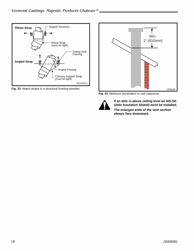
• The minimum height of the vent above the highestpoint of penetration through the roof is 2’ (610mm).(Fig. 32)

17
Vermont Castings, Majestic Products Chateau™
20006081
Vertical Through-the-Roof Installation
Attic Installation
Ceiling Installation
Nails (4)
Firestop Spacer
Joist
Joist
Firestop Spacer
Nails (4)FP593
Fig. 31 Installing firestop spacer.
1 2
3
4
Max. 8’ (2.4m)
FP1245a
Fig. 30 Typical offset application.
1 + 2 + 3 + 4 = 270°
Minimum 2’ (610mm)Before Any Elbow
1. Locate your fireplace.2. Plumb to center of the (8”) flue collar from ceiling
above and mark position.3. Cut opening equal to 14¹⁄₂” x 14¹⁄₂” (368mm x
368mm).4. Proceed to plumb for additional openings through
the roof. In all cases, the opening must provide aminimum of 1¹⁄₂” (38mm) clearance to the vent pipe,i.e., the hole must be at least 14¹⁄₂” x 14¹⁄₂” (368 mmx 368mm).
5. Place fireplace into position.6. Place firestop(s) SKFS2A or Attic Insulation Shield
AIS-SK into position and secure. (Figs. 31, 32)7. Install roof support (Fig. 33) and roof flashing
making sure upper flange of flashing is below theshingles.
8. Install appropriate pipe sections until the venting isabove the flashing.
9. Seal around the pipe.10. Add additional vent lengths for proper height. (Fig.
34)
AtticInsulationShield
CeilingBaseFlanges
Nails (4Required)
Attic Joist
FP263
Fig. 32 Attic shield installation.
18
Vermont Castings, Majestic Products Chateau™
20006081
If an attic is above ceiling level an AIS-SK(Attic Insulation Shield) must be installed.
The enlarged ends of the vent sectionalways face downward.
Min.2’ (610mm)
CFM190
Fig. 34 Minimum termination to roof clearance.
Support Structure
Elbow Strap(must be tight)
Ceiling HoleFraming
Angled Firestop
Chimney Support Strap(must be tight)
FP270/271
Elbow Strap
Angled Strap
Fig. 33 Attach straps to a structural framing member.

19
Vermont Castings, Majestic Products Chateau™
20006081
Chimney Components
Horizontal Starter Kit Contains 24”-40” telescopic pipe* for minimum vertical SK8DVSKrise from collar pipe, 90° elbow, horizontalthrough-wall starter pipe, zero clearance sleeve,metal adhesive tape, sidewall termination and firestop.
SK8 Chimney Sections Pipe used to build 8" (SK8) flue systems. SK81 (1' Long)SK818 (1Z\x' Long)SK83 (3' Long)SK84 (4' Long)
SK8 Chimney Elbows Elbow used to create an offset in an 8" SK830-2 30° Elbow*chimney system. (2 per pkg.)
SK845 45° Elbow*SK890 90° Elbow*
Firestop Required at each floor level of chimney SKFS2A —installation. (Plus attic on multi-story installation.) (8" straight flue)
SK8DVFS(Horizontal Firestop)
Zero Clearance Sleeve Used when horizontal pipe goes through an interior SK8ZCSvertical wall.
Attic Insulation Shield Used to prevent insulation from coming in contact with AIS-SKthe chimney system.
Chimney Support Used to support chimney for each of: 30' vertical SKCS8height and 6' of angled chimney run.
Round Top Termination Top used to terminate chimney at roof.(Flashing not included.) RLTSK8
Round Top Termination - Top used to terminate chimney at chase.Extended (Flashing not included.) RLTSK8L
Flashing Metal finishing required around termination 8-6-12 with 8" flue:to prevent rain leakage. 0-6/12 pitch
8-12-12 with 8" flue:6/12-12/12 pitch
Housing Extensions Extends Square Termination on steep 202036pitched roofs.
Chase Top Housing Low profile pyramid-style chimney cap used to PTLSK8terminate chimney through a chase. Includesadapter. (Flashing not included.)
Chase Top Housing Square chimney cap used to terminate chimney SLTSK8through a chase. Terra Cotta Masonry. Includesadapter. (Flashing not included.)
Horizontal Termination Cap used to terminate venting through a sidewall. SK8DVRVT
Model NumberDescriptionComponent
NOTE: The 24”-40” telescopic pipe is only intended for use with the SK8DVSK.* Factory unitized elbow

20
Vermont Castings, Majestic Products Chateau™
20006081
Only glass approved by VermontCastings, Majestic Products should beused on this fireplace.
1. Turn the fireplace OFF (including the pilot).2. If the unit has been operating allow time for the
components to cool.3. Using a Phillips screwdriver, unfasten two (2) screws
located at the top of the glass frame. (Fig. 35)4. Tilt the glass frame at the top away from the unit. Lift
it carefully off the bottom door track and set onpadded surface.
It is necessary to periodically clean the glass. Duringstart-up, condensation, which is normal, forms on theinside of the glass. This condensation causes lint, dustand other airborne particles to cling to the glasssurface.
Also initial paint curing may deposit a slight film on theglass. It is therefore recommended the glass becleaned two or three times with a non-ammonia basedhousehold cleaner and warm water (gas fireplace glasscleaner is recommended) within the first few weeks ofoperation.
After the initial cleaning process the glass should becleaned two or three times during each operatingseason depending on the environment in the house.
Clean the glass after the first two weeksof operation.
• The use of any non-approved replacement glass willvoid all product warranties.
• Care must be taken to avoid breakage of the glass.• Do not operate appliance with glass front
removed, cracked or broken.• A replacement glass frame assembly (complete
with gasket) is available through your VermontCastings, Majestic Products dealer and shouldonly be installed by a licensed qualified serviceperson.
Operating InstructionsGlass Information
Glass Frame Assembly Removal
Glass Cleaning
Restrictor Plates Installation
Refer to Pages 13 & 16 for your venting configurationand combination of restrictor plate requirement andfresh air restrictor plate adjustment.
Restrictor Plate Installation
Using the two (2) screws provided along with therestictor plate shipped with the logset, fasten therestrictor plate to the firebox top through the front ofthe unit. (Fig. 36)
PhillipsScrews
FP1363
Fig. 35 Remove Phillips screws, tilt frame forward and liftoff bottom door track.
Flue Opening
Restric-tor Plate
Sheet MetalScrews
FP1364
Fig. 36 Restrictor plate location.
DVT44Use tin snips to cutalong slots to make 4¹⁄₂”(114mm) restrictor plate.(Refer to Page 13)
DVT38Use tin snips to cutalong outer slots tomake 4¹⁄₂” (114mm)restrictory plate. (Referto Page 16, Fig. 28)
DVT38Use tin snips tocut along innerslots to make 3”restrictor plate.(Refer to Page 13)
21
Vermont Castings, Majestic Products Chateau™
20006081
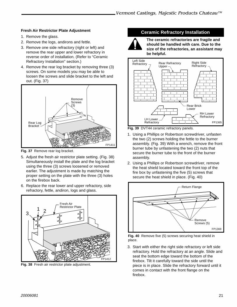
Fresh Air Restrictor Plate Adjustment
1. Remove the glass.2. Remove the logs, andirons and fettle.3. Remove one side refractory (right or left) and
remove the rear upper and lower refractory inreverse order of installation. (Refer to “CeramicRefractory Installation” section.)
4. Remove the rear log bracket by removing three (3)screws. On some models you may be able toloosen the screws and slide bracket to the left andout. (Fig. 37)
Rear LogBracket
RemoveScrews(3)
Fig. 37 Remove rear log bracket.
FP1411
5. Adjust the fresh air restrictor plate setting. (Fig. 38)Simultaneously install the plate and the log bracketusing the three (3) screws loosened or removedearlier. The adjustment is made by matching theproper setting on the plate with the three (3) holeson the firebox back.
6. Replace the rear lower and upper refractory, siderefractory, fettle, andiron, logs and glass.
1 23
Fresh AirRestrictor Plate
FP1412
Fig. 38 Fresh air restrictor plate adjustment.
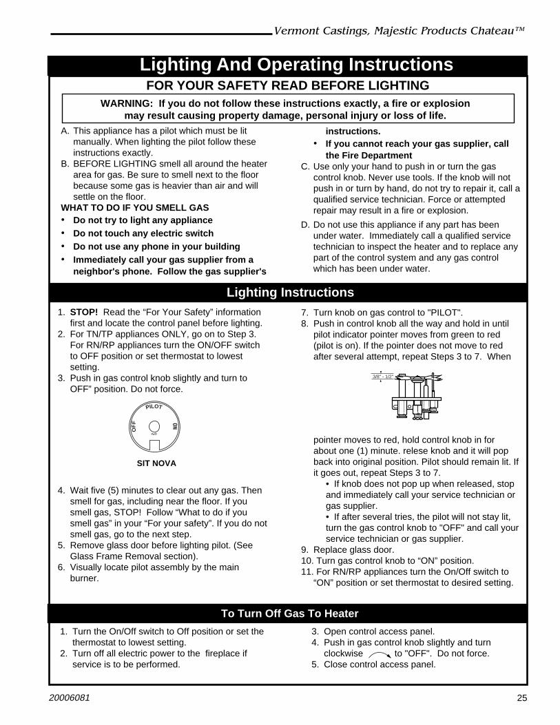
Ceramic Refractory Installation
The ceramic refractories are fragile andshould be handled with care. Due to thesize of the refractories, an assistant maybe helpful.
Left SideRefractory Rear Refractory
Upper
Rear BrickLower
RH LowerRefractory
LH LowerRefractory
Right SideRefractory
FP1365
Fig. 39 DVT44 ceramic refractory panels.
1. Using a Phillips or Robertson screwdriver, unfastenthe two (2) screws holding the fettle to the burnerassembly. (Fig. 39) With a wrench, remove the frontburner tube by unfastening the two (2) nuts thatsecure the burner tube to the front of the burnerassembly.
2. Using a Phillips or Robertson screwdriver, removethe heat shield located toward the front top of thefire box by unfastening the five (5) screws thatsecure the heat shield in place. (Fig. 40)
RemoveScrews (5)
FP1369
Fig. 40 Remove five (5) screws securing heat shield inplace.
Return Flange
3. Start with either the right side refractory or left siderefractory. Hold the refractory at an angle. Slide andseat the bottom edge toward the bottom of thefirebox. Tilt it carefully toward the side until thepiece is in place. Slide the refractory forward until itcomes in contact with the front flange on thefirebox.

22
Vermont Castings, Majestic Products Chateau™
20006081
Volcanic Rock LG292
Fig. 42 Place volcanic rock on lower refractory in front ofburner housing.
Ember Material
Small Lava Rock
LG293
Fig. 43 Place ember material on burner tube. Place smalllava rock 1¹⁄₂” on burner housing.
4. Holding the rear refractory lower straight up, rotateit back behind the side refractory and set it on thesmall return bend of the rear log bracket toward theback of the firebox. Ensure the mortar lines in therefractory match the side refractory already in-stalled.
5. Rotate back and set on the rear log bracket towardthe back of the firebox.
6. The rear refractory upper has a notch in the topside. Holding the refractory at an angle, slide therefractory behind the side refractory installed.
7. While holding the rear refractory upper in place,follow Step 3 and install the remaining side refrac-tory.
8. Adjust all refractory pieces so mortar lines arealigned. Replace heat shield removed in Step 2.Make sure the angle on the heat shield goes back.This will secure the side refractory in place.
9. Slide the right and left lower refractories into placein front of the burner and align.
10. Reinstall the burner tube and fettle.
Log, Lava Rock and Ember Placement
Unpack the logs from packaging and remove each logfrom its wrapping material.
The logs are fragile and should behandled with care. Keep the packagingmaterials out of the reach of children anddispose of the material in a safe manner.
1. Ensure the two (2) screws that attach the fettle tothe burner are secure.
2. Set the andirons in place by hooking the tabs on theback of the andirons over the outermost webs of thefettle. (Fig. 41)
3. Place the volcanic rock over the lower refractory infront of the burner tube and around the burnerassembly as desired. (Fig. 42)
4. Place the ember material lightly in front over theburner tube. Cover the area between the burnertube and the burner pan assembly. (Fig. 43)
Andirons
Fettle
Burner Tube
BurnerHousing
LG291
Fig. 41 Ensure fettle is securely attached to the burnerhousing and set andirons in place.
5. Place the small lava rock 1¹⁄₂” (38mm) along the topfront edge of the burner pan assembly.
Refer to Figures 47 & 48 for final log positions.6. Center the log rear onto the rear log bracket and
slide back until it comes in contact with the rearrefractory lower. (Fig. 44)
7. Hold the log front left with the narrower end towardthe right. For DVT44, set the log on the inside leftside of the fettle and bring it forward until the rightend of the log comes through the opening in thefettle. For the DVT38, the log is placed the same,however the end will not come through the fettle.When in place, the left end of the log is supportedabove the left sheet metal bracket. DVT38, the logwill just touch the left side refractory. (Fig. 45)
8. Hold the log right front with the pointed end towardthe left. Set the log on the inside right side of thefettle and bring forward. The pointed end of the logshould come in contact with the front left log. Whenin place, the right end of the log is supported abovethe sheet metal bracket toward the right. (Fig. 45)

23
Vermont Castings, Majestic Products Chateau™
20006081
Log Rear F1
LG294
Fig. 44 Place log rear onto rear log bracket.
Log LeftFront F3
Log RightFront F2
LG295
Fig. 45 Place logs left front and right front.
9. Hold the log top right front to back with the narrowerend toward the back. With your left hand, tilt thefront left log slightly up and forward. With your righthand position the fat end of the top right log on thesmall shelf on the back of the front right log. Lowerthe two logs in place until the narrower end of thetop right log comes in contact and rests on the topright side of the rear log. (Fig. 46)
10. Hold the log top left at an angle with the burnedarea toward the middle. Set the top left log abovethe front left log, matching the indentation on thebottom of the top left log with the protrusion on thefront left log. Lay the back end of the top left logonto the rear log. (Fig. 46)
11. Hold the log top middle at an angle with the curveof the log going from right to left. Position the frontend of the top middle log over the right front log,matching the protrusion on the right front log withthe indentation on the bottom of the top middle log.Lay the back end of the middle log onto the rear logand swing the end of the log from right to left untilthe end of the top middle log comes in contact withthe top left log. (Fig. 46)
LG297
Fig. 47 DVT44 logset.
Log Top Middle F5
Log Top RightF4
Log TopLeft F6
LG296
Fig. 46 Place middle logs.
LG315
Fig. 48 DVT38 logset.

24
Vermont Castings, Majestic Products Chateau™
20006081
It is important to periodically perform a visual check ofthe pilot and burner flames. Compare them to theillustratrations below. (Figs. 50, 51, 52)If the flame patterns appear abnormal contact aqualified service provider for service and adjustment.
Flame Characteristics
LO
HITurn counterclockwise
to increaseflame height
Turn clockwiseto decreaseflame height
SIT 820 Valve
Fig. 49 Flame adjustment knob for SIT valve.LG290
Fig. 51 DVT44 burner flame pattern.
Flame & Temperature Adjustment
RN/RP & EN/EP Models
For units equipped with ‘HI/LO’ valves the flameadjustment is accomplished by rotating the ‘HI/LO’adjustment knob located near the center of the gascontrol valve. (Fig. 49)
LG316
Fig. 52 DVT38 burner flame pattern.
3/8" - 1/2"
SIT Top Convertible
SIT EN/EP
FP1229a
Fig. 50 Correct pilot flame appearance.
25
Vermont Castings, Majestic Products Chateau™
20006081
3. Open control access panel.4. Push in gas control knob slightly and turn
clockwise to "OFF". Do not force.5. Close control access panel.
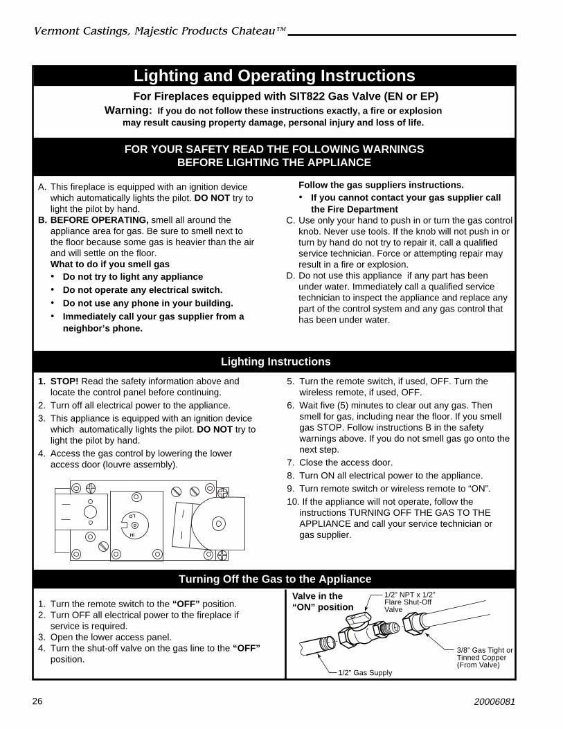
1. STOP! Read the “For Your Safety” informationfirst and locate the control panel before lighting.
2. For TN/TP appliances ONLY, go on to Step 3.For RN/RP appliances turn the ON/OFF switchto OFF position or set thermostat to lowestsetting.
3. Push in gas control knob slightly and turn toOFF” position. Do not force.
7. Turn knob on gas control to "PILOT".8. Push in control knob all the way and hold in until
pilot indicator pointer moves from green to red(pilot is on). If the pointer does not move to redafter several attempt, repeat Steps 3 to 7. When
FOR YOUR SAFETY READ BEFORE LIGHTING
instructions.• If you cannot reach your gas supplier, call
the Fire DepartmentC. Use only your hand to push in or turn the gas
control knob. Never use tools. If the knob will notpush in or turn by hand, do not try to repair it, call aqualified service technician. Force or attemptedrepair may result in a fire or explosion.
D. Do not use this appliance if any part has beenunder water. Immediately call a qualified servicetechnician to inspect the heater and to replace anypart of the control system and any gas controlwhich has been under water.
A. This appliance has a pilot which must be litmanually. When lighting the pilot follow theseinstructions exactly.
B. BEFORE LIGHTING smell all around the heaterarea for gas. Be sure to smell next to the floorbecause some gas is heavier than air and willsettle on the floor.
WHAT TO DO IF YOU SMELL GAS• Do not try to light any appliance• Do not touch any electric switch• Do not use any phone in your building• Immediately call your gas supplier from a
neighbor's phone. Follow the gas supplier's
To Turn Off Gas To Heater
Lighting And Operating Instructions
1. Turn the On/Off switch to Off position or set thethermostat to lowest setting.
2. Turn off all electric power to the fireplace ifservice is to be performed.
Lighting Instructions
4. Wait five (5) minutes to clear out any gas. Thensmell for gas, including near the floor. If yousmell gas, STOP! Follow “What to do if yousmell gas” in your “For your safety”. If you do notsmell gas, go to the next step.
5. Remove glass door before lighting pilot. (SeeGlass Frame Removal section).
6. Visually locate pilot assembly by the mainburner.
pointer moves to red, hold control knob in forabout one (1) minute. relese knob and it will popback into original position. Pilot should remain lit. Ifit goes out, repeat Steps 3 to 7.
• If knob does not pop up when released, stopand immediately call your service technician orgas supplier.• If after several tries, the pilot will not stay lit,turn the gas control knob to "OFF" and call yourservice technician or gas supplier.
9. Replace glass door.10. Turn gas control knob to “ON” position.11. For RN/RP appliances turn the On/Off switch to
“ON” position or set thermostat to desired setting.
WARNING: If you do not follow these instructions exactly, a fire or explosionmay result causing property damage, personal injury or loss of life.
SIT NOVA
ON
PILOT
OFF
OFF
3/8" - 1/2"
26
Vermont Castings, Majestic Products Chateau™
20006081
Lighting and Operating InstructionsFor Fireplaces equipped with SIT822 Gas Valve (EN or EP)
A. This fireplace is equipped with an ignition devicewhich automatically lights the pilot. DO NOT try tolight the pilot by hand.
B. BEFORE OPERATING, smell all around theappliance area for gas. Be sure to smell next tothe floor because some gas is heavier than the airand will settle on the floor.What to do if you smell gas• Do not try to light any appliance• Do not operate any electrical switch.• Do not use any phone in your building.• Immediately call your gas supplier from a
neighbor’s phone.
FOR YOUR SAFETY READ THE FOLLOWING WARNINGSBEFORE LIGHTING THE APPLIANCE
1. STOP! Read the safety information above andlocate the control panel before continuing.
2. Turn off all electrical power to the appliance.3. This appliance is equipped with an ignition device
which automatically lights the pilot. DO NOT try tolight the pilot by hand.
4. Access the gas control by lowering the loweraccess door (louvre assembly).
Follow the gas suppliers instructions.• If you cannot contact your gas supplier call
the Fire DepartmentC. Use only your hand to push in or turn the gas control
knob. Never use tools. If the knob will not push in orturn by hand do not try to repair it, call a qualifiedservice technician. Force or attempting repair mayresult in a fire or explosion.
D. Do not use this appliance if any part has beenunder water. Immediately call a qualified servicetechnician to inspect the appliance and replace anypart of the control system and any gas control thathas been under water.
5. Turn the remote switch, if used, OFF. Turn thewireless remote, if used, OFF.
6. Wait five (5) minutes to clear out any gas. Thensmell for gas, including near the floor. If you smellgas STOP. Follow instructions B in the safetywarnings above. If you do not smell gas go onto thenext step.
7. Close the access door.8. Turn ON all electrical power to the appliance.9. Turn remote switch or wireless remote to “ON”.10. If the appliance will not operate, follow the
instructions TURNING OFF THE GAS TO THEAPPLIANCE and call your service technician orgas supplier.
1. Turn the remote switch to the “OFF” position.2. Turn OFF all electrical power to the fireplace if
service is required.3. Open the lower access panel.4. Turn the shut-off valve on the gas line to the “OFF”
position.
Warning: If you do not follow these instructions exactly, a fire or explosionmay result causing property damage, personal injury and loss of life.
Lighting Instructions
Turning Off the Gas to the Appliance
HI
LO
FP297A
Valve in the“ON” position
1/2” Gas Supply
1/2” NPT x 1/2”Flare Shut-OffValve
3/8” Gas Tight orTinned Copper(From Valve)

27
Vermont Castings, Majestic Products Chateau™
20006081
Troubleshooting the Gas Control System
NOTE: Before trouble shooting the gas control system, be sure external gas shut off is in the “On” position.SIT NOVA 820 MILLIVOLT VALVE
Symptom
1. Spark ignitor will not light
2. Pilot will not stay lit aftercarefully followinglighting instructions
3. Pilot burning, no gas tomain burner
4. Frequent pilot outageproblem
Possible Causes
A. Defective or misaligned electrodeat pilot
B. Defective ignitor (Push Button)
A. Defective pilot generator (ther-mocouple), remote wall switch
B. Defective automatic valve
A. Wall switch or wires defective
B. Thermopile may not be generat-ing sufficient millivoltage
C. Plugged burner orifice
D. Defective automatic valveoperator
A. Pilot flame may be too low orblowing (high) causing the pilotsafety to drop out
B. Possible blockage of the ventterminal
Corrective Action
Using a match, light pilot. If pilot lights, turn off pilotand push the red button again. If pilot will not light -check gap at electrode and pilot-should be 1/8” tohave a strong spark.
With the control knob in the pilot position, push thecontrol knob all the way and hold. Check for spark atelectrode and pilot. If no spark to pilot, and electrodewire is properly connected, replace the battery in theignitor module and try again. Refer toMaintenanceSection. If the problem still exists, replace the ignitormodule box.
Check pilot flame. Must impinge on thermocouple/thermopile. NOTE: This pilot burner assembly utilizesboth a thermocouple and a thermopile. The thermo-couple operates the main valve operation (On andOff). Clean and or adjust pilot for maximum flameimpingement on thermopile and thermocouple.
Turn valve knob to “Pilot”. Maintain flow to pilot;millivolt meter should read greater than 10mV. If thereading is okay and the pilot does not stay on, replacethe gas valve. NOTE: An interrupter block (notsupplied) must be used to conduct this test.
Check wall switch and wires for proper connections.Jumper wire across terminals at wall switch, if burnercomes on, replace defective wall switch.. If okay,jumper wires across wall switch wires at valve, ifburner comes on, wires are faulty or connections arebad.
1. Be sure wire connections form thermopile at gasvalve terminals are tight and thermopile is fullyinserted into pilot bracket.
2. One of the wall switch wires may be grounded.Remove wall switch wires form valve terminals ifpilot now stays lit, trace wall switch wiring forground. May be grounded to fireplace or gassupply.
3. Check thermopile with millivolt meter. Take readingat thermopile terminals of gas valve. Should read250-300 millivolts (minimum 150) while holdingvalve knob depressed in pilot position and wallswitch “Off”. Replace faulty thermopile if reading isbelow specified minimum.
Check burner orifices for debris and remove.
Turn valve knob to “On”, place wall switch to “On”millivolt meter should read greater than 150mV. If thereading is okay and the burner does not come on,replace the gas valve.
Clean and/or adjust pilot flame for maximum flameimpingement on thermopile and thermocouple.
Check the vent terminal for blockage (recycling theflue gases).
28
Vermont Castings, Majestic Products Chateau™
20006081
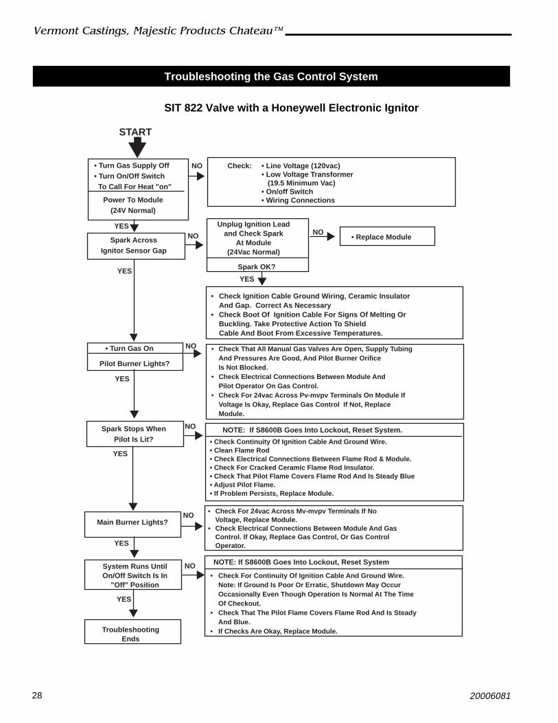
SIT 822 Valve with a Honeywell Electronic Ignitor
Troubleshooting the Gas Control System
START
• Turn Gas Supply Off• Turn On/Off Switch To Call For Heat "on"
Power To Module(24V Normal)
Spark AcrossIgnitor Sensor Gap
YES
YES
YES
• Turn Gas On
Pilot Burner Lights?
Spark Stops WhenPilot Is Lit?
Main Burner Lights?
System Runs UntilOn/Off Switch Is In
"Off" Position
TroubleshootingEnds
YES
YES
YES
NO
NO
NO
NO
NO
NO
Check: • Line Voltage (120vac)• Low Voltage Transformer (19.5 Minimum Vac)• On/off Switch• Wiring Connections
Unplug Ignition Leadand Check Spark
At Module(24Vac Normal)
Spark OK?
• Replace Module
• Check Ignition Cable Ground Wiring, Ceramic Insulator And Gap. Correct As Necessary
• Check Boot Of Ignition Cable For Signs Of Melting Or Buckling. Take Protective Action To ShieldCable And Boot From Excessive Temperatures.
• Check That All Manual Gas Valves Are Open, Supply TubingAnd Pressures Are Good, And Pilot Burner Orifice Is Not Blocked.
• Check Electrical Connections Between Module AndPilot Operator On Gas Control.
• Check For 24vac Across Pv-mvpv Terminals On Module If Voltage Is Okay, Replace Gas Control If Not, Replace Module.
NOTE: If S8600B Goes Into Lockout, Reset System.
• Check Continuity Of Ignition Cable And Ground Wire.• Clean Flame Rod• Check Electrical Connections Between Flame Rod & Module.• Check For Cracked Ceramic Flame Rod Insulator.• Check That Pilot Flame Covers Flame Rod And Is Steady Blue• Adjust Pilot Flame.• If Problem Persists, Replace Module.
• Check For 24vac Across Mv-mvpv Terminals If NoVoltage, Replace Module.
• Check Electrical Connections Between Module And GasControl. If Okay, Replace Gas Control, Or Gas ControlOperator.
NOTE: If S8600B Goes Into Lockout, Reset System
• Check For Continuity Of Ignition Cable And Ground Wire.Note: If Ground Is Poor Or Erratic, Shutdown May OccurOccasionally Even Though Operation Is Normal At The Time Of Checkout.
• Check That The Pilot Flame Covers Flame Rod And Is Steady And Blue.
• If Checks Are Okay, Replace Module.
NO
YES

29
Vermont Castings, Majestic Products Chateau™
20006081
Fuel Conversion Instructions
WARNING! This conversion kit shall be installedby a qualified service agency in accordance withthe manufacturer’s instructions and all applicablecodes and requirements of the authority havingjurisdiction. If the information in these instructionsis not followed exactly, a fire, explosion or produc-tion of carbon monoxide may result causingproperty damage, personal injury or loss of life.The qualified service agency is responsible for theproper installation of this kit. The installation is notproper and complete until the operation of theconverted appliance is checked as specified in themanufacturer’s instructions supplied with the kit.
CAUTION: The gas supply shall be shut off prior todisconnecting the electrical power, before pro-ceeding with the conversion.
Avertissement: Cette trousse de conversionNe doit être installée que par le représentant d’unorganisme qualifié et conformément aux instruc-tions du fabricant et aux codes et exigencespertinentes de l’autorité compétente. Quiconquene respecte pas à la lettre les instrucitons duprésent guide risque de déclencher un incendie,une explosion ou le dégagement de monoxyde decarbone entraînant des dommages matériels, deslésions corporelles ou la perte de vies humaines.L’organisme qualifié qui effectur les travaux estresponsible de l’installation de cette trousse.L’installation n’est pas terminée tant que lefonctionnement de l’appareil converti n’a pas étévérifié selon la notice du fabricant quiaccompagne la trousse.
ATTENTION: Avant d’effectuer la conversin, coupezd’abord l’limentation en gaz, ensuite, coupezl’alimentation électrique.
Conversion Precautions
Allow unit to cool if it has been operating.
Before proceeding with conversion, turn control knob onvalve to OFF and turn gas supply OFF. Turn OFF anyelectricity that may be going to appliance.
Conversion Procedure
1. Remove glass frame. Refer to Glass Frame Assemblysection on Page 20.
2. Remove lava rock, volcanic rock, embers and logs.CAUTION: Logs may be hot.
3. With a Phillips or Robertson screwdriver, remove thetwo (2) screws holding the fettle to the burner assem-blies. With a hex, remove the two (2) hex nuts holding
the burner tube to the front of the burner assembly.Remove burner tube.
4. Remove two (2) hex nuts holding the left burner leg.Remove burner leg. (Fig. 53)
Pilot Hood
PilotBracket
CO105a
Fig. 54 Remove pilot hood.
Index Tab Allen Wrench
Snap Ring
CO106a
Fig. 55 Remove pilot orifice.
KT416
Fig. 53 Use 3/8” socket to remove hex nuts holding left burnerleg.
5. Slide the burner housing assembly to the left andaway.
6. Replace the three (3) injectors. Refer to Table 1.7. Replace pilot orifice.8. Remove pilot hood by lifting up. (Fig. 54) NOTE: It is
not necessary to remove the pilot tube for conversion.9. Remove pilot orifice with 5/32” Allen wrench. (Fig. 55)

30
Vermont Castings, Majestic Products Chateau™
20006081
Pilot Flame Adjustment
Typically, the top 3/8” or 1/2” of the thermopile shouldbe engulfed in the pilot flame. (Page 24, Fig. 50)To adjust pilot burner:
1. Remove pilot adjustment cap located on valve.2. Adjust pilot screw to provide properly sized
flame.3. Replace pilot adjustment cap.
10. Install the conversion orifice.11. Reinstall pilot hood. Be sure to align hood with index
tab.12. Open the control panel and remove the cover by
removing two (2) screws. While holding the valvecover plate with one hand, disconnect the wiring tothe switch and the pilot indicator. NOTE: Do not allowthe valve cover plate to hang from the pilot wires asthis could damage the wires. Remove the extensionknob(s). Replace the valve regulator.
13. Using the TORX T20 bit remove and discard thethree (3) pressure regulator mounting screws (A),pressure regulator tower (B) and the spring anddiaphragm assembly (C). (Fig. 56)
14. Insure the rubber gasket (D) is properly positionedand install the new HI/LO pressure regulator assem-bly to the valve using the new screws (E) suppliedwith the kit. Tighten the screws securely. (Ref. torque= in/lb) (Fig. 57)
15. Install the enclosed identification label (F) to thevalve body where it can easily be seen. (Fig. 57)
16. Regulator conversion complete.17. Test for Leaks
• Apply gas to the system and light the pilot.• With a soapy solution check for leaks around the
pilot assembly where the tube enters the pilotassembly. Tighten fitting if necessary.
• Light the main burner and check for leaks aroundthe new pressure regulator assembly. Tightenscrews if necessary.
• With the main burner “ON” check for leaks aroundthe burner orifice. Be careful of the burner flame.Tighten orifice if necessary.
• With the main burner “ON” rotate the HI/LO knoband verify proper burner operation.
18. Replace burner to original position.19. Replace burner leg.20. Replace burner tube and fettle.21. Follow instructions on Page 22 to reinstall logs, lava
rock, volcanic rock and embers.22. Replace glass frame.Conversion complete.
Fig. 57 Replace regulator.
D
E
F
OFFPILOTON
FC108
Fig. 56 Remove valve regulator.
A
B
C
OFF
PILOTON
FC107
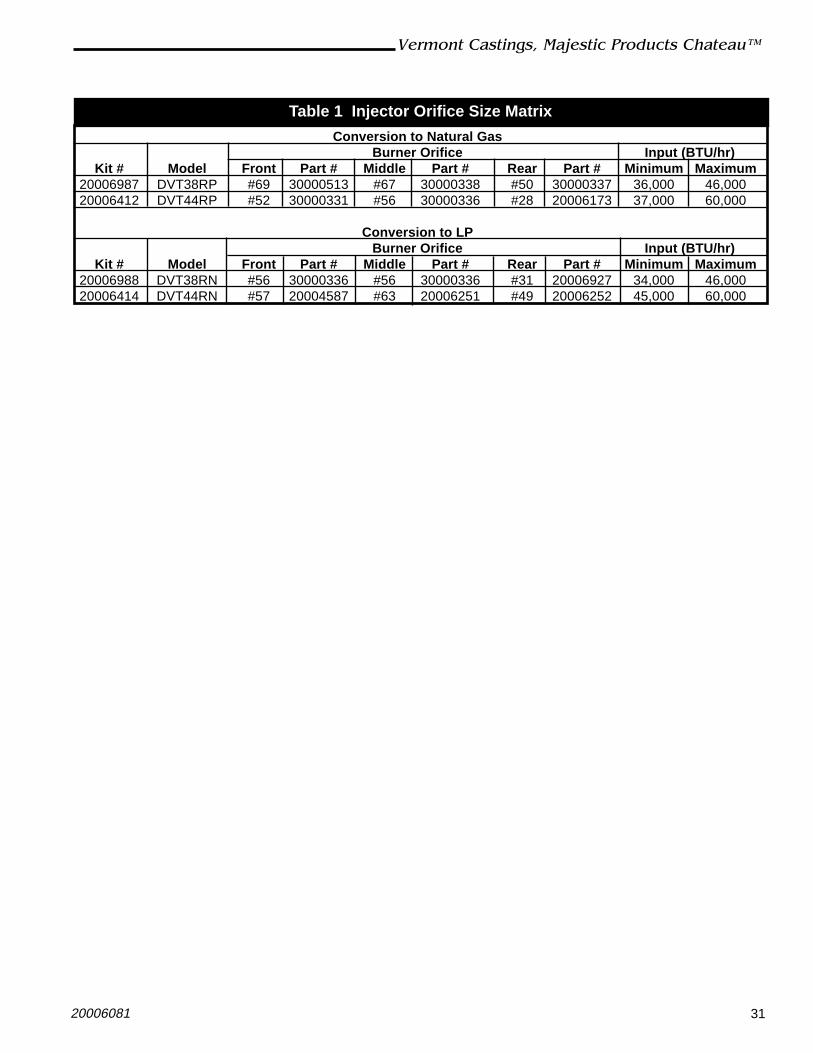
31
Vermont Castings, Majestic Products Chateau™
20006081
Conversion to Natural GasBurner Orifice Input (BTU/hr)
Kit # Model Front Part # Middle Part # Rear Part # Minimum Maximum20006987 DVT38RP #69 30000513 #67 30000338 #50 30000337 36,000 46,00020006412 DVT44RP #52 30000331 #56 30000336 #28 20006173 37,000 60,000
Conversion to LPBurner Orifice Input (BTU/hr)
Kit # Model Front Part # Middle Part # Rear Part # Minimum Maximum20006988 DVT38RN #56 30000336 #56 30000336 #31 20006927 34,000 46,00020006414 DVT44RN #57 20004587 #63 20006251 #49 20006252 45,000 60,000
Table 1 Injector Orifice Size Matrix

32
Vermont Castings, Majestic Products Chateau™
20006081
MaintenanceBurner and Burner Compartment
It is important to keep the burner and the burnercompartment clean. At least once per year the logsand lava rock/ember material should be removed andthe burner compartment vacuumed and wiped out.Remove and refit the logs as per the instructions in thismanual.
Always handle the logs with care as theyare fragile and may also be hot if thefireplace has been in use.
Cleaning the StandingPilot Control System
The burner and control system consist of:
• burner tube • gas orifice• pilot assembly • thermopile• gas valve
Most of these components may require only anoccasional checkup and cleaning and some mayrequire adjustment. If repair is necessary, it shouldbe performed by a qualified technician.
1. Turn off pilot light at gas valve.2. Allow fireplace to cool if it has been operating.3. Remove window frame assembly. (Refer to Window
Frame Assembly Removal section.)4. Remove logs.5. Vacuum burner compartment especially around
orifice primary air openings.6. Visually inspect pilot. Brush or blow away any dust
or lint accumulation.7. Reinstall logs.8. Ignite pilot - Refer to Lighting Instructions.9. Reinstall window frame assembly.To obtain proper operation, it is imperative that thepilot and burner’s flame characteristics are steady, notlifting or floating.
Typically, the top 3/8” to 1/2” of the thermopile/sensingelectrode should be engulfed in the pilot flame. (Referto Page 24, Figure 48)
To adjust pilot burner: (by qualified service technician)
1. Remove pilot adjustment cap
2. Adjust pilot screw to provide properly sized flame.
3. Replace pilot adjustment cap.
Cleaning Electronic Ignition SystemThe Electronic Ignition burner/control system consistsof:
• main burner• gas orifice• pilot burner• 24VAC valve with transformer
Taking care of the Electronic Ignition units is identical totaking care of the Standing Pilot models.
Battery Replacement for Ignitor Module1. Open control panel box door.
2. Remove the extension knob(s).3. Remove the valve cover by removing the two (2)
screws securing the valve cover plate to the box.While holding the valve cover plate with one hand,disconnect the wiring to the switch and the pilotindicator. NOTE: Do not allow the valve cover plateto hang from the pilot indicator wires as this coulddamage the wires.
4. Replace the battery (AA) in the ignitor modulelocated at the top left corner.
5. Replace wires, valve cover, extension knob(s) inreverse order. NOTE: The pilot indicator body islabelled +/-, make sure the positive wire on the pilotindicator goes to ground and the negative goes tothe plug between the valve and the thermocouple.

33
Vermont Castings, Majestic Products Chateau™
20006081
1a
1c
1b
1d1e1f
1
2
3
4
4d
4e
4a
4b
4f4c
6
7
8
9a,b10a,b11a,b
12a,b
HI
LO
OFF
ON
OFF
PILOTOF
F
EA
PILOT
TH
TP
TP
TH
12c,d
13a,b
13c,d
18
MV MVPV PVGND(BURNER)
24VGND 24V SENSE SPARK
19
20
26OF
FPILOT
ONit LO
HI
21 22
23
24
25
27
14 15
16b
17
1h
1i
1g
1j
5
9a,b
10a,b11a,b
28a,b
29
16a
Vermont Castings, Majestic Products reserves the right to make changes in design, materials, specifications, prices and discontinue colors andproducts at any time, without notice.
DVT38, DVT44
6081

34
Vermont Castings, Majestic Products Chateau™
20006081
DVT38, DVT44 (continued)Ref. Description DVT38 DVT44
1. Log Set (Complete) 20006961 200063781a. Log Rear F1 20006970 200063301b. Log Right Front F2 20006971 200063311c. Log Left Front F3 20006972 200063321d. Log Top Right F4 20006333 200063331e. Log Top Middle F5 20006334 200063341f. Log Top Left F6 20006335 200063351g. Small Lava Rock Package 57897 578971h. Volcanic Rock 20000376 200003761i. Bag of Glowing Embers 0005219 00052191j. Restrictor 20006959 200058172. Andiron Assembly 20006291 200064913. Fettle 20006960 200059774. Refractory Set Complete 20006823 20006384
4a. Rear Refractory Lower 20006589 200058244b. Rear Refractory Upper 20006590 200058254c. Right Side Refractory 20006591 200058264d. Left Side Refractory 20006592 200058274e. LH Lower Refractory 20006593 200058764f. RH Lower Refractory 20006594 200058795. Spring Latch Assembly 20005788 200057886. Burner Housing Assembly 20006576 200058347. Burner Tube Assembly 20006584 200058848. Manifold Tube Assembly 20005852 20005852
9a. Front Orifice #52 (.635”) - Natural -- 300003319a. Front Orifice #56 (.0465”) - Natural 30000336 --9b. Front Orifice #57 (,043”) - LP -- 200045879b. Front Orifice #69 (.0292”) - LP 30000513 --
10a. Middle Orifice #56 (.0465”) - Natural 30000336 3000033610b. Middle Orifice #63 (.037”) - LP -- 2000625110b. Middle Orifice #67 (.032”) - LP 30000338 --11a. Rear Orifice #28 (.1405”) - Natural -- 2000617311a. Rear Orifice #31 (.120”) - Natural 20006927 --11b. Rear Orifice #49 (.073”) - LP -- 2000625211b. Rear Orifice #50 (.070”) - LP 30000337 --12a. Valve Nova SIT 0.820.652 - RN 52677 5267712b. Valve Nova SIT 0.820.651 - RP 52678 5267812c. Valve Nova SIT 0.822.632 - EN 57884 57884
24v/60Hz Solenoid Manual HI/LO12d. Valve Nova SIT 0.822.631 - EP 57883 57883
24v/60Hz Solenoid Manual HI/LO13a. Pilot Assy 3way N/DV Top Convertible - RN 20006144 2000614413b. Pilot Assy 3way N/DV Top Convertible - RP 20006145 2000614513c. Pilot Assy 3way N/DV Top Convertible - EN 20006146 2000614613d. Pilot Assy 3way N/DV Top Convertible - EP 20006147 20006147

35
Vermont Castings, Majestic Products Chateau™
20006081
DVT38, DVT44 (continued)Ref. Description DVT38 DVT4414. Thermopile 75” 20006148 2000614815. Thermocouple 72” 20006149 20006149
16a. Electrode Ignitor 79” RN/RP 20006150 2000615016b. Electrode Ignitor 79” EN/EP 20008059 20008059
17. Sensing Electrode 79” 20006151 2000615118. Transformer 7522409 752240919. Ignitor Module Honeywell 58600B1025 20000005 2000000520. Glass Frame Assembly 20006566 2000594721. Knob Extension Pilot/Stat 10000166 1000016622. Knob Extension HI/LO 10000165 1000016523. Pilot Indicator 20005908 2000590824. Ignitor Module 20005909 2000590925. Pilot Indicator Plug 20006250 2000625026. Switch Rocker 53606 5360627. Spark Cable Connection 20005807 20005807
28a. Outer Pipe Aluminum Foil Tape 20006169 2000616928b. Inner Pipe Aluminum Foil Tape 20008253 20008253
29. Plate, Restrictor 20006663 2000675730. Milpack Tube (not shown) 53326 53326
Fuel Conversion KitsConversion Kit, NG to LP
DVT44RN & EN Kit # 20006414DVT38RN & EN Kit # 20006988
Conversion Kit, LP to NGDVT44RP & EP Kit # 20006412DVT38RP & EP Kit # 20006987
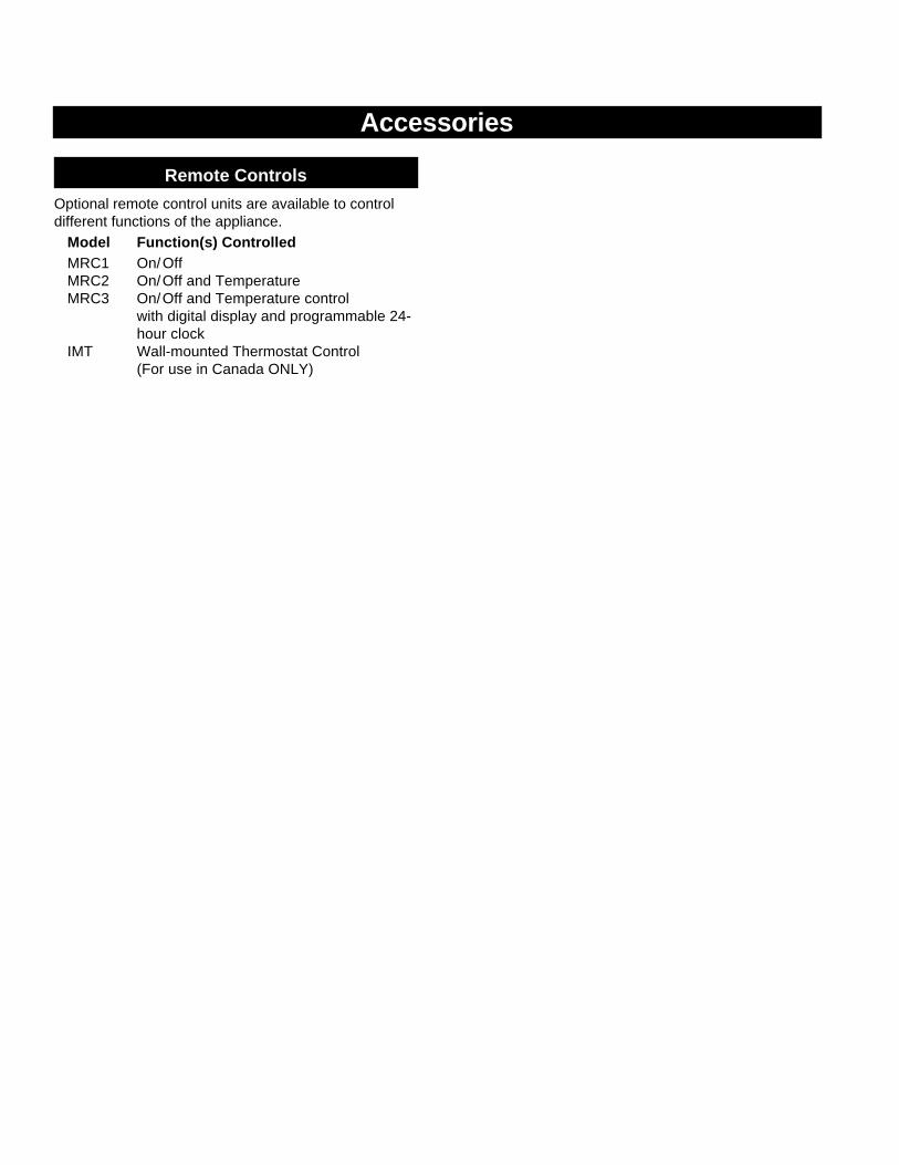
Accessories
Remote Controls
Optional remote control units are available to controldifferent functions of the appliance.
Model Function(s) ControlledMRC1 On/OffMRC2 On/Off and TemperatureMRC3 On/Off and Temperature control
with digital display and programmable 24-hour clock
IMT Wall-mounted Thermostat Control(For use in Canada ONLY)

BASIC WARRANTY
Vermont Castings, Majestic ProductSs (hereinafter referred tocollectively as the Company) warrants that your new Vermont Castingsor Majestic Gas Fireplace/Stove is free from manufacturing andmaterial defects for a period of one year from the date of purchase,subject to the following conditions and limitations.
EXTENDED LIFETIME WARRANTY
The heat exchanger, where applicable, and combustion chamber ofevery Vermont Castings or Majestic gas product is warranted for lifeagainst through wall perforation. All appliances equipped with anInsta-Flame Ceramic Burner have limited lifetime coverage on theceramic burner plaque. Warrantees are made to the original ownersubject to proof of purchase and the conditions and limitations listedon this Warranty Document
COMPONENT WARRANTY
CAST IRON: All external and internal cast iron parts are warranted for aperiod of three years.
Note: On porcelain enamel finished external parts and accessoriesThe Company offers no Warranty on chipping of enamel surfaces.Inspect all product prior to accepting it for any damage to the enamel.
The salt air environment of coastal areas or a high humidityenvironment can be corrosive to the porcelain enamel finish. Theseconditions can cause rusting of the cast iron beneath the porcelainenamel finish, which will cause the finish to flake off.
Dye lot variations with replacement parts and/or accessories canoccur and are not covered by warranty.
GLASS DOORS: Glass doors are covered for a period of one year.Glass doors are not warranted for breakage due to misuse oraccident. Glass doors are not covered for discoloration or burned instains due to environmental issues, or improper cleaning andmaintenance.
BRASS PLATED PARTS AND ACCESSORIES: Brass parts should becleaned with Lemon oil only. Brass cleaners cannot be used. Mortarmix and masonry cleaners may corrode the brass finish. TheCompany will not be responsible for, nor will it warrant any brass partswhich are damaged by external chemicals or down draft conditions.
GAS VALVES: Gas valves are covered for a period of one year
ELECTRONIC AND MECHANICAL COMPONENTS: Electronic andmechanical components of the burner assembly are covered for oneyear. All steel tube burners are warranted for one year.
ACCESSORIES: Unless otherwise noted all components and VermontCastings, Majestic Products company supplied accessories are coveredfor a period of one year.
CONDITIONS AND LIMITATIONS
• This new Vermont Castings or Majestic product must be installed bya competent, authorized, service contractor. A licensed technician,as prescribed by the local jurisdiction must perform any installation/service work. It must be installed and operated at all times inaccordance with the Installation and Operating instructions furnishedwith the product. Any alteration, willful abuse, accident, or misuse ofthe product shall nullify this warranty.
• This warranty is non-transferable, and is made to the original owner,provided that the purchase was made through an authorized supplierof the Company.
• The customer must pay for any Authorized Dealer in-home travel feesor service charges for in-home repair work. It is the dealers optionwhether the repair work will be done in the customer’s home or in thedealer’s shop.
• If upon inspection, the damage is found to be the fault of themanufacturer, repairs will be authorized at no charge to the customerparts and/or labor.
• Any part and/or component replaced under the provisions of thiswarranty is covered for six months or the remainder of the originalwarranty, whichever is longest.
• This warranty is limited to the repair of or replacement of part(s) foundto be defective in material or workmanship, provided that such part(s)have been subjected to normal conditions of use and service, aftersaid defect is confirmed by the Company’s inspection.
• The company may, at its discretion, fully discharge all obligations withrespect to this warranty by refunding the wholesale price of thedefective part(s)
• Any installation, labor, construction, transportation, or other relatedcosts/expenses arising from defective part(s), repair, replacement, orotherwise of same, will not be covered by this warranty, nor shall theCompany assume responsibility for same. Further, the Company willnot be responsible for any incidental, indirect, or consequentialdamages except as provided by law.
• SOME STATES DO NOT ALLOW FOR THE EXCLUSION ORLIMITATIONS OF INCIDENTAL AND CONSEQUENTIAL DAMAGESOR LIMITATIONS ON HOW LONG AN IMPLIED WARRANTY LASTS,SO THE ABOVE LIMITATIONS MAY NOT APPLY TO YOURCIRCUMSTANCES. THIS WARRANTY GIVES YOU SPECIFICRIGHTS AND YOU MAY HAVE OTHER RIGHTS WHICH VARYFROM STATE TO STATE.
• All other warranties-expressed or implied- with respect to the product,its components and accessories, or any obligations/liabilities on thepart of the Company are hereby expressly excluded.
• The Company neither assumes, nor authorizes any third party toassume on its behalf, any other liabilities with respect to the sale ofthis Vermont Castings, Majestic product
• The warranties as outlined within this document do not apply tochimney components or other non Vermont Castings, Majesticaccessories used in conjunction with the installation of this product..
• Damage to the unit while in transit is not covered by this warranty butis subject to claim against the common carrier. Contact the dealerfrom whom you purchased your fireplace/stove (do not operate theappliance as this might negate the ability to process the claim with thecarrier).
• The Company will not be responsible for:
a) Down drafts or spillage caused by environmental conditions suchas near-by trees, buildings, roof tops, hills, or mountains.
b) Inadequate ventilation or negative air pressure caused bymechanical systems such as furnaces, fans, clothes dryers, etc.
• This warranty is void if:
a) The fireplace has been operated in atmospheres contaminatedby chlorine, fluorine, or other damaging chemicals.
b) The fireplace has been subjected to prolonged periods ofdampness or condensation
c) Any damages to the fireplace, combustion chamber, heatexchanger or other components due to water, or weather damage,which is the result of but not limited to, improper chimney/ventinginstallation.
d) Any alteration, willful abuse, accident, or misuse of the producthas occurred.
IF WARRANTY SERVICE IS NEEDED…
1) Contact your supplier. Make sure you have your warranty,your sales receipt, and the model/serial number of yourVermont Castings, Majestic product.
2) DO NOT ATTEMPT TO DO ANY SERVICE WORKYOURSELF.
LIMITED LIFETIME WARRANTYPRODUCT COVERED BY THIS WARRANTYAll Vermont Castings gas stoves, gas inserts, and gas fireplaces, and all Majestic or Northern Flame brand gas fireplacesequipped with an Insta-Flame Ceramic Burner, or standard steel tube burner.

410 Admiral Blvd. • Mississauga, Ontario, Canada L5T 2N6 • 905-670-7777www.majesticproducts.com • www.vermontcastings.com
CFM Specialty Home Products
Top Related