44 DV XXL Owner’s Manual - Kirkland...
60
TM • Direct Vent Fireplace • Natural Gas or Propane • Standard Residential • Mobile Home Approved Tested and Listed by Omni-Test Laboratories, Inc. Beaverton,Oregon Report# 028-5-26-5 ANSI Z21.88,CSA2.33 M9 8,CAN/CGA2.17-M91 WARNING: If the information in these instructions are not followed exactly, a fire or explosion may result causing property damage, personal injury or loss of life. - Do not store or use gasoline or other flammable vapors and liquids in the vicinity of this or any other appliance. WHAT TO DO IF YOU SMELL GAS • Do not try to light any appliance. • Do not touch any electrical switch; do not use any phone in your building. • Immediately call gas supplier from a neighbor's phone. Follow the gas supplier's instructions. • If you cannot reach your gas supplier, call the fire department. - Installation and service must be performed by a qualified installer, service agency or the gas supplier. This appliance may be installed as an OEM installation in a manufactured (mobile) home and must be installed in accordance with the manufacturer’s instructions and the manufactured home construction and safety standard, Title 24 CFR, Part 3280 or Standard for Installation in Mobile Homes, CAN/CSA Z240 MH. This appliance is only for use with the type(s) of gas indicated on the rating plate. A conversion kit is supplied with the appliance. 44 DV XXL Owner’s Manual Installer : After installation give this manual to the homeowner and explain operation of this fireplace. $10.00 Copyright 2003, T.I. Part # 93508112 403205 10850 117th Place N.E. Kirkland, WA 98033
Transcript of 44 DV XXL Owner’s Manual - Kirkland...
TM
• Direct Vent Fireplace
• Natural Gas or Propane
• Standard Residential
• Mobile Home Approved
Tested and Listed by
Omni-Test Laboratories, Inc.Beaverton, OregonReport # 028-5-26-5
ANSI Z21.88, CSA 2.33 M9 8, CAN/CGA 2.17-M91
WARNING: If the information in these instructions are not followed exactly, a fire orexplosion may result causing property damage, personal injury or loss of life.
- Do not store or use gasoline or other flammable vapors and liquids in the vicinity of this orany other appliance.
WHAT TO DO IF YOU SMELL GAS• Do not try to light any appliance.• Do not touch any electrical switch; do not use any phone in your building.• Immediately call gas supplier from a neighbor's phone. Follow the gas supplier's instructions.• If you cannot reach your gas supplier, call the fire department.
- Installation and service must be performed by a qualified installer, service agency or the gassupplier.
This appliance may be installed as an OEM installation in a manufactured (mobile) home andmust be installed in accordance with the manufacturer’s instructions and the manufacturedhome construction and safety standard, Title 24 CFR, Part 3280 or Standard for Installation inMobile Homes, CAN/CSA Z240 MH.
This appliance is only for use with the type(s) of gas indicated on the rating plate. A conversionkit is supplied with the appliance.
44 DV XXL Owner’s ManualInstaller: After installation give this manual to the
homeowner and explain operation of thisfireplace.
$10.00 Copyright 2003, T.I. Part # 93508112403205
10850 117th Place N.E. Kirkland, WA 98033


Introduction 1
Travis Industries 403205 93508112
Introduction
We welcome you as a new owner of a Fireplace Xtrordinair gas fireplace. In purchasing a FireplaceXtrordinair you have joined the growing ranks of concerned individuals whose selection of an energysystem reflects both a concern for the environment and aesthetics. The Fireplace Xtrordinair is one ofthe finest home heaters the world over. This manual will explain the installation, operation, andmaintenance of this fireplace. Please familiarize yourself with the Owner's Manual before operatingyour heater and save the manual for future reference. Included are helpful hints and suggestions thatwill make the operation and maintenance of your new fireplace an easier and more enjoyableexperience. We offer our continual support and guidance to help you achieve the maximum benefitand enjoyment from your heater.
Important InformationNo other Fireplace Xtrordinair gas fireplace has thesame serial number as yours. The serial number isbelow and to the left of the gas control valve.
This serial number will be needed in case you requireservice of any type.
Model: 44 DV XXL (SIT)
Serial Number:
Purchase Date:
Purchased From:
Mail your Warranty CardToday, and Save Your Bill ofSa le .
To receive full warranty coverage,you will need to show evidence ofthe date you purchased yourheater. Do not mail your Bill ofSale to us.
We suggest that you attach yourBill of Sale to this page so that youwill have all the information youneed in one place should the needfor service or information occur.

2 Safety Precautions
Travis Industries 403205 93508112
• IF YOU SMELL GAS:* Do not light any appliance
* Extinguish any open flame
* Do not touch any electrical switch or plug or unplug anything
* Open windows and vacate building
* Call gas supplier from neighbor's house, if not reached, call firedepartment
• This unit must be installed by a qualified installer to prevent thepossibility of an explosion. Your dealer will know the requirements inyour area and can inform you of those people considered qualified. Theroom heater should be inspected before use and at least annually by aqualified service person. More frequent cleaning may be required dueto excessive lint from carpeting, bedding material, etc.
• The instructions in this manual must be strictly adhered to. Do not use makeshiftmethods or compromise in the installation. Improper installation will void the warranty andsafety listing.
For LPG only | Pout 11” W.C.
Look for this label:
If the label is present, the heater is equipped for LP (propane). If the label is absent, the heater is equipped for NG (natural gas).
• This heater is either approved for naturalgas (NG) or for propane (LP or LPG).Burning the incorrect fuel will void thewarranty and safety listing and may causean extreme safety hazard. Directquestions about the type of fuel used toyour dealer. Check for the label shown tothe right.
Ok
• Contact your local buildingofficials to obtain a permitand information on anyinstallation restrictions orinspection requirements inyour area. Notify yourinsurance company of thisheater as well.
• If the flame becomes sooty,dark orange in color, orextremely tall, do notoperate the heater. Callyour dealer and arrange forproper servicing.
AAAAAAA
• It is imperative that controlcompartments, screens, orcirculating air passagewaysof the heater be kept cleanand free of obstructions.These areas provide the airnecessary for safeoperation.
?• Do not operate the heater if
it is not operating properly inany fashion or if you areuncertain. Call your dealerfor a full explanation of yourheater and what to expect.
Gas
• Do not store or use gasolineor other flammable liquids inthe vicinity of this heater.
AAAAAAA
AAAAAAAAAAAA
AAAAAAAAAAAAAA
• Do not use this appliance ifany part has been underwater. Immediately call aqualified service technicianto inspect the appliance andto replace any part of thecontrol system and any gascontrol which has beenunder water.

Safety Precautions 3
Travis Industries 403205 93508112
AAAAAAA
• Do not place clothing orother flammable items on ornear the heater. Becausethis heater can be controlledby a thermostat there is apossibility of the heaterturning on and igniting anyitems placed on or near it.
AAAAAAAAA
• Light the heater using thebuilt-in piezo igniter. Do notuse matches or any otherexternal device to light yourheater.
• Never remove, replace,modify or substitute any partof the heater unless
AAAAAAAAAAA
• The viewing glass should beopened only for lighting thepilot or conducting service.
• Any safety screen or guardremoved for servicing mustbe replaced prior tooperating the heater.
• Do not operate with theglass removed or damaged.
instructions are given in thismanual. All other work mustbe done by a trainedtechnician. Don't modify orreplace orifices.
• Allow the heater to coolbefore carrying out anymaintenance or cleaning.
• Operate the heateraccording to the instructionsincluded in this manual.
• If the main burners do notstart correctly turn the gasoff at the gas control valveand call your dealer forservice.
• The pilot flame must contactthe thermopile andthermocouple (see theillustration to the left). If itdoes not, turn the gascontrol valve to "OFF" andcall your dealer.
AAAAAAAAAAA • This unit is not for use with
solid fuel
• Do not place anything insidethe firebox (except theincluded fiber logs).
• If the fiber logs becomedamaged, replace withTravis Industries log set.
ThisManual
• Do not throw this manualaway. This manual hasimportant operating andmaintenance instructionsthat you will need at a latertime. Always follow theinstructions in this manual.
AAAAAAA
• Do not touch the hotsurfaces of the heater.Educate all children of thedanger of a high-temperature heater. Youngchildren should besupervised when they are inthe same room as theheater.
AAAAAAA
36"
• Keep all furniture or othercombustible items at least36" away from the front ofthe fireplace (this includesdrapes or doors that mayswing within 36" of the frontof the fireplace).
• Instruct everyone in thehouse how to shut gas off tothe appliance and at the gasmain shutoff valve. The gasmain shutoff valve is usuallynext to the gas meter orpropane tank and requires awrench to shut off.
• Travis Industries, Inc.grants no warranty,implied or stated, forthe installation ormaintenance of yourheater, and assumesno responsibility of anyconsequentialdamage(s).
4 Table of Contents
Travis Industries 403205 93508112
IntroductionIntroduction & Important Information................1
Safety PrecautionsSafety Precautions ......................................2
Features & SpecificationsFeatures ....................................................5Installation Options......................................5Heating Specifications..................................5Dimensions.................................................5
InstallationInstallation Warning......................................6Packing List................................................6Additional Items Required for Installation..........6Installation Overview....................................6Fireplace Placement Requirements..................7
Minimum Framing Dimensions ....................7Clearances ............................................8Vertical Stand-Off ...................................8Corner Installations .................................9Raised Fireplaces....................................9
Hearth Requirements....................................10Facing Requirements....................................11Facing Over 1" Thick.....................................11Facing Detail ...............................................12Face Dimensions .........................................13Facing and Hearth Examples..........................14Mantel Requirements....................................16Vent Requirements.......................................17
Altitude Considerations ............................17Clearances ............................................17Part Numbers (8" Dia. Pipe) .......................17Vent Installation......................................18
Approved Vent Configurations........................19Restrictor Position...................................19Elbows..................................................19Measuring Vent Lengths...........................19Vertical Term. 0,2 or 4 45° Offsets ..............20Horizontal Term. with One Vert. Elbow .........21Horizontal Term. with Three Vert. Elbows......22Vertical Term. with Two Elbows...................23
Vent Termination Requirements ......................24Gas Line Requirements.................................25
Fuel ......................................................25Gas Line Connection................................25Gas Inlet Pressure ..................................25
Electrical Connection....................................26
Finalizing the Installation1 Glass Removal (& installation)......................272 Log Installation .........................................283 Replace the Glass .....................................334 Faceplate Installation.................................335 Leak Test.................................................336 Pilot Adjustment (if necessary).....................337 Air Shutter Adjustment (if necessary) ............348 Check Flame.............................................359 Explain Operation to Home-Owner.................35
OperationBefore You Begin.........................................36Location of Controls .....................................36Starting The Pilot .........................................37Starting the Fireplace for the First Time.............38Turning the Fireplace On and Off .....................38Adjusting the Flame Height.............................38Adjusting the Blower Speed............................39Optional Power Heat Duct Operation................39Normal Operating Sounds..............................39Normal Operating Odors................................39
MaintenanceYearly Service Procedure..............................40Troubleshooting Table...................................41How this Fireplace Works...............................42
What Turns the Main Burners On and Off......42What Prevents Gas Buildup.......................42
Wiring Diagram ............................................43Replacement Parts List .................................43
Safety LabelSafety (Listing) Label....................................44
WarrantyWarranty ....................................................45
Optional EquipmentLP Conversion Kit ........................................46Power Heat Duct ..........................................50Decorative Refractories (Classic & Brick) .........56
Index Index.........................................................58

Features and Specifications 5
Travis Industries 403205 93508112
Features:- Works During Power Outages (millivolt system)- High Efficiency- Optional Thermostat or Remote Control- Realistic "Wood Fire" Look- Two Quiet Blowers for Effective Heat Distribution- Convenient Operating Controls- Variable-Rate Heat Output- Low Maintenance
Installation Options:- Residential or Mobile Home- Straight or Corner Placement- Flush or Recessed Face- Raised or Floor Hearth- Internal or External Chase- Horizontal or Vertical Vent- Power Heat Duct
Heating Specifications: Natural Gas PropaneApproximate Heating Capacity (in square feet)* Up to 3,000 Up to 3,000BTU Input Per Hour (from high to low) 58, 000 – 30,000 58, 000 – 30,000BTU Output on High (with blowers on) 42,920 44,080Efficiency** (with blowers on) 74 % 76 %AFUE (Annual Fuel Utilization Efficiency) 68 % 69 %* Heating capacity will vary with floor plan, insulation, use of Power Heat Duct, and outside temperature.
** Efficiency rating is a product thermal efficiency rating determined under continuous operation independent ofinstalled system.
The electrical connection is made in the lower right rear corner.
24-1/8"*
51-3/4"*
1" Stand-offs
* Includes the required
1" clearance.
Nail Down Plate (used to secure the fireplace to the floor)
8-7/8"*
Vent has an external diameter of 8"
Weight: 325 Lbs.
Dimensions:
Gas Inlet (on both sides)
1"
6-1/4"
10-1/2"
42-3/4"
31-3/8"
3-7/8"
7-5/8"
27-1/2"
27-5/8"
1"
6-1/2"
2-3/8"
5-3/8"*
5-1/4"*37-7/8"*
3-1/8"
40"
WARNING:
A 1" clearance from the
fireplace enclosure is
required along the sides
and back of the fireplace.
Power Heat Vent Hook-Up
Thermostat Wire Hole(on both sides)

6 Installation (for qualified installers only)
Travis Industries 403205 93508112
Installation Warnings:! Failure to follow all of the requirements may result in property damage, bodily
injury, or even death.! This heater must be installed by a qualified installer who has gone through a
training program for the installation of direct vent gas appliances.! This appliance must be installed in accordance with all local codes, if any; if not, in
U.S.A. follow ANSI Z223.1 and NFPA 54(88), in Canada follow B-149.! In Manufactured or Mobile Homes must conform with: In USA, Manufactured Home
Construction and Safety Standard, Title 24 CFR, Part 3280; In Canada, CSA Z240.4and Gas-Equipped Recreational Vehicles and Mobile Housing. This appliance maybe installed in Manufactured Housing only after the home is site located.
! The 44 DV XXL is designed to operate on natural gas or propane (LP).! All exhaust gases must be vented outside the structure of the living-area.
Combustion air is drawn from outside the living-area structure.! Notify your insurance company before hooking up this fireplace.! The requirements listed below are divided into sections. All requirements must be
met simultaneously. The order of installation is not rigid – the qualified installershould follow the procedure best suited for the installation.
Packing List• Propane Conversion Kit• Log Set (Log Set, Coals, & Glowing Embers)• Flex Tube with Pipe Adapter• Glass Latch Tool (to un-latch glass frame)• Arch Covers (for arched face)• Firestop (manufactured for the 44 DV XXL)
Additional Items Required• Faceplate - Includes attachment screws• Direct Vent (Simpson Dura-Vent Ph. # 800 835-4429)• Gas Line Equipment (shutoff valve, pipe, etc.)• Electrical Equipment (min. 18 gauge, grounded line)
Installation Overview
AAAAAAAAAAAAAAAA
AAAAAAAAAAAAAAAAAAAAAAAA
AAAAAAAAAAAAAAAAAAAAAAAA
AAAAAAAAAAAAAAAAAAAAAAAA
AAAAAAAAAAAAAAAA
Non-combustible facing (see the section "Facing Requirements")
See the section "Acceptable Vent Lengths"
See the section "Horizontal Termination Requirements"
See the section "Gas Line Installation"
See the section "Electrical Connection"
See the section "Mantel Requirements"
Insulation must not fill the 1" clearance around the back and sides of the fireplace.
See the section "Fireplace Placement Requirements"
3-1/2" Min.
See the section "Vent Requirements"
See the section "Minimum Framing Dimensions"
See the section "Hearth Requirements"
Drywall
Nail Down Plate
See "Power Heat Vent" in the optional equipment section.
This grommet and hole is for thermostat wire (on both sides)
Installation (for qualified installers only) 7
Travis Industries 403205 93508112
Fireplace Placement Requirements
Minimum Framing Dimensions
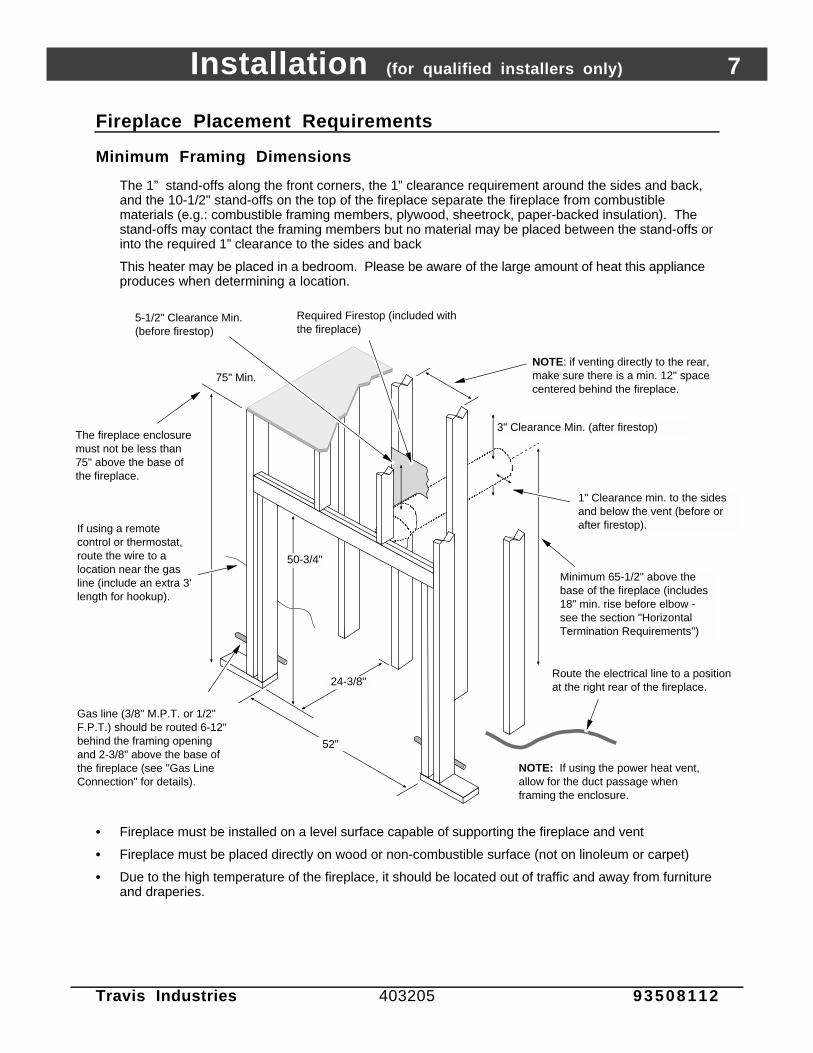
The 1” stand-offs along the front corners, the 1” clearance requirement around the sides and back,and the 10-1/2" stand-offs on the top of the fireplace separate the fireplace from combustiblematerials (e.g.: combustible framing members, plywood, sheetrock, paper-backed insulation). Thestand-offs may contact the framing members but no material may be placed between the stand-offs orinto the required 1” clearance to the sides and back
This heater may be placed in a bedroom. Please be aware of the large amount of heat this applianceproduces when determining a location.
AAAAAAAAAAAA
A
AAAAAAAAAAAA
AAAAAAAAAAA
AAAAAAAAAAAA
Gas line (3/8" M.P.T. or 1/2" F.P.T.) should be routed 6-12" behind the framing opening and 2-3/8" above the base of the fireplace (see "Gas Line Connection" for details).
52"
24-3/8"
50-3/4"
Route the electrical line to a position at the right rear of the fireplace.
If using a remote control or thermostat, route the wire to a location near the gas line (include an extra 3' length for hookup).
NOTE: if venting directly to the rear, make sure there is a min. 12" space centered behind the fireplace.
NOTE: If using the power heat vent, allow for the duct passage when framing the enclosure.
Required Firestop (included with the fireplace)
3" Clearance Min. (after firestop)
Minimum 65-1/2" above the base of the fireplace (includes 18" min. rise before elbow - see the section "Horizontal Termination Requirements")
5-1/2" Clearance Min. (before firestop)
1" Clearance min. to the sides and below the vent (before or after firestop).
The fireplace enclosure must not be less than 75" above the base of the fireplace.
75" Min.
• Fireplace must be installed on a level surface capable of supporting the fireplace and vent
• Fireplace must be placed directly on wood or non-combustible surface (not on linoleum or carpet)
• Due to the high temperature of the fireplace, it should be located out of traffic and away from furnitureand draperies.
8 Installation (for qualified installers only)
Travis Industries 403205 93508112
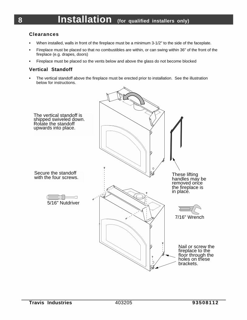
Clearances
• When installed, walls in front of the fireplace must be a minimum 3-1/2" to the side of the faceplate.
• Fireplace must be placed so that no combustibles are within, or can swing within 36" of the front of thefireplace (e.g. drapes, doors)
• Fireplace must be placed so the vents below and above the glass do not become blocked
Vertical Standoff
• The vertical standoff above the fireplace must be erected prior to installation. See the illustrationbelow for instructions.
The vertical standoff is shipped swiveled down. Rotate the standoff upwards into place.
5/16" Nutdriver
Secure the standoff with the four screws.
These lifting handles may be removed once the fireplace is in place.
7/16" Wrench
Nail or screw the fireplace to the floor through the holes on these brackets.
Installation (for qualified installers only) 9
Travis Industries 403205 93508112
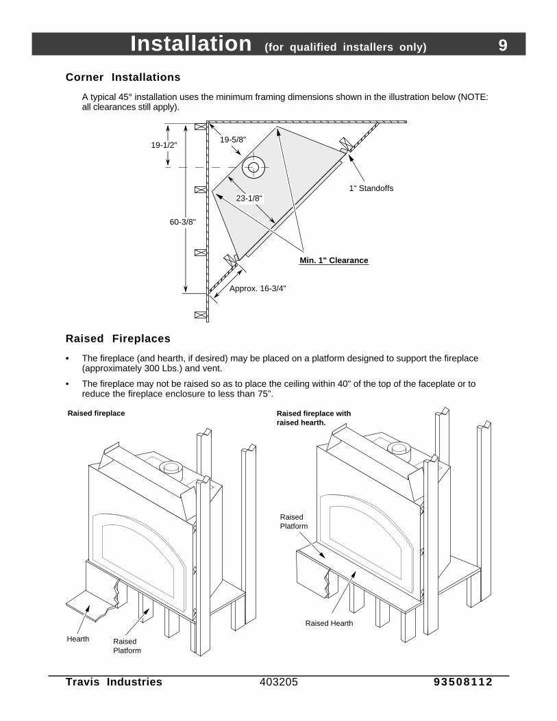
Corner Installations
A typical 45° installation uses the minimum framing dimensions shown in the illustration below (NOTE:all clearances still apply).
AAAAAAAAA
AAAAAA
AAAAAAAAAAAAAAAAAAAAA
Approx. 16-3/4"
23-1/8"1" Standoffs
19-5/8"19-1/2"
Min. 1" Clearance
60-3/8"
Raised Fireplaces
• The fireplace (and hearth, if desired) may be placed on a platform designed to support the fireplace(approximately 300 Lbs.) and vent.
• The fireplace may not be raised so as to place the ceiling within 40" of the top of the faceplate or toreduce the fireplace enclosure to less than 75”.
Raised fireplace Raised fireplace with raised hearth.
Raised Platform
Raised Hearth
Hearth
Raised Platform
6-1/4"
6-1/4"
10 Installation (for qualified installers only)
Travis Industries 403205 93508112
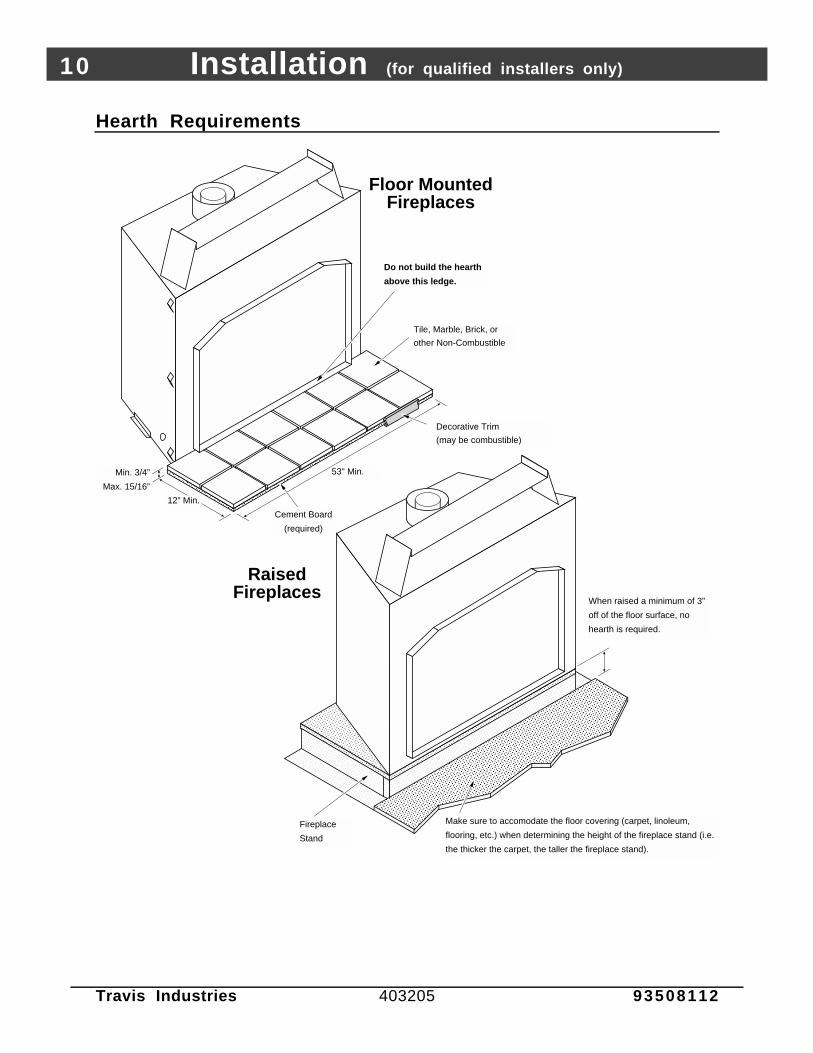
Hearth Requirements
6-1/4"
AAAAAAAAAAAAAAAAAAAAAAAAAAAAAAAAAAAAAAAAAAAAAAAAAAAAAAAAAAAAAAAAAAAAAAAAAAAAAAAAAAAAAAAAAAAAAAAAAAAAAAAAA
AAAAAAAAAAAAAAAAAAAAAAAAAAAAAAAAAAAAAAAAAAAAAAAAAAAAAAAAAAAAAAAAAAAAAAAAAAAAAAAAAAAAAAAAAAAAAAAAAAAAAAAAAAAAAAAAAAAAAAAAAAAAAAAAAAAAAAA
Do not build the hearth
above this ledge.
12” Min.
53" Min.
Cement Board
(required)
Tile, Marble, Brick, or
other Non-Combustible
Decorative Trim
(may be combustible)
Min. 3/4”
Max. 15/16”
Floor Mounted Fireplaces
Raised Fireplaces
AAAAAAAAAAAAAAAAAAAAAAAAAAAAAAAAAAAAAAAAAAAAAAAAAAAAAAAAAAAAAAAAAAAAAAAAAAAAAAAAAAAAAAAAAAAAAAAAAAAAAAAAAAAAAAAAAAAAAAAAAAAAAAAAAAAAAAAAAAAAAAAAAAAAAAAAAAAAAAAAAAAAAAAAAAAAAAAAAAAAAAAAAAAAAAAAAAAAAAAAAAAAAAAAAAAAAAAAAAAAAAAAAAAA
AAAAAAAAAAAAAAAAAAAAAAAAAAAAAAAAAAAAAAAAAAAAAAAAAAAAAAAAAAAAAAAAAAAAAAAAAAAAAAA
AAAAAAAAAAAAAAAAAAAAAAAAAAAAAAAAAAAAAAAAAAAAAAAAAAAAAAAAAAAAAAAAAAAAAAAAAAAAAAAAAAAAAAAAAAAAAAAAAAAAAAAAAAAAAAAAAAAAAAAAAAAAAAAAAAAAAAA
AAAAAAAAAAAAAAAAAAAAAAAAAAAAAAAAAAAAAAAAAAAAAAAAAAAAAAAAAAAAAAAAAAAAAAAAAAAAA
AAAAAAAAAAAAAAAAAAAAAAAAAAAAAAAAAAAAAAAAAAAAAAAAAAAAAAAAAAAAAAAAAAAAAAAAAAAAAAAAAAAAAAAAAAAAAAAAAAAAAAAAAAAAAAAAAAAAAAAAAAAAAAAAAAAAAAAAAAAAAAAA
AAAAAAAAAAAAAAAAAAAAAAAA
When raised a minimum of 3”
off of the floor surface, no
hearth is required.
AAAAAAAAAAAAAAAAAAAAAAAA
Make sure to accomodate the floor covering (carpet, linoleum,
flooring, etc.) when determining the height of the fireplace stand (i.e.
the thicker the carpet, the taller the fireplace stand).
Fireplace
Stand
6-1/4"

Installation (for qualified installers only) 11
Travis Industries 403213 93508112
Facing Requirements
NOTE: The combustible area above the facing must not protrude more than 3/4" from the facing. If itdoes, it is considered a mantel and must meet the mantel requirements listed in this manual.
NOTE: The facing may be attached to the front of the fireplace with screws. Do not penetrate thefireplace more than 3/4”.
AAAAAAAAAAAAAAAAAAAAAAAAAAAAAA
3-1/2" Min.(both sides)
Non-combustible Facing
AAAAAAAAAAAAAAAAAAAAAAAAAAAAAAAAAAAAAAAAAAAAAAAAAAAAAAAAAAAAAAAAAAAAAAAAAAAAAAAAAAAAAAAAAAAAAAAAAAAAAAAAAAAAAA
The fireplace requires a concrete board (or other non-combustible) extending from the header to the floor and to the framing members on both sides. Do not use sheetrock, plywood or other combustible.
14" Min.Header
34-7/8"
Base of Fireplace
46"
Set-Up Face (shipped in place)
Facing Over 1"Thick
• If the facing material isover 1" thick (e.g. brick,river rock), install thefacing around theperimeter of the set-upface shipped with thefireplace. See theillustration to the right.
• Artisan faces vary insize. Use the facebeing installed tocreate a template.
AAAAAAAAAAAAAAAAAAAAAAAAAAAAAAAAAAAAAAAAAAAAAAAAAAAAAAAAAAAAAAAAAAAAAAAAAAAAAAAAAAAAAAAA
AAAA
AAAAAAAAAAAAAAAAAAAAAAAAAAAAAAAAAAAAAAAAAAAAAAAAAAAAAAAAAAAAAAAAAAAAAAAAAAAAAAAAAAAAAAAAAAAAAAAA
AAAAAAAAAAAAAAAAAAAAAAAAAAAAAAAAAAAAAAAAAAAAAAAAAAAAAAAAAAAAAAAAAAAAAAAAAAAAAAAAAAAA
AAAAAAAAAAAAAAAAAAAAAAAAAAAAAAAAAAAAAAAAAAAAAAAAAAAAAAAAAAAAAAAAAAAAAAAAAAAAAAAAAAAAAAAAAAAAAAAAAAAAAAAAAAAAAAAAAAAAAAAAAAAAAAAAAAAAAAAAAAAAAAAAAAAAAAAAAAAAAAAAAAAAAAAAAA
AAAA
Set-Up Face(shipped with the fireplace - 1/16” taller and 1/8” wider than the finished face)1”
Note: if using a brick hearth, the fireplace will need to be raised to accommodate the 1” gap betwen the face and the base of the fireplace. For 2-1/2” thick brick this works out to approximately 1-1/2” (we recommend 1-5/8” to accomodate irregular surfaces).
Note: The brick tucks below the face template.
AAAAAAAAAAAAAAAAAAAAAAAAAAAAAAAAAAAAAAAAAAAAAAAAAAAAAAAAAAAAAAAAAAAAAAAAAAAAAAAAAAAAAAAAAAAAAAAAAAAAAAAAAAAA
AAAAAAAAAAAAAAAAAAAAAAAAAAAAAAAAAAAAAAAAAAAAAAAAAAAAAAAAAAAAAAAAAAAAAAAAAAAAAAAAAAAA
AAA
The brick facing must meet the same requirements listed “Facing Requirements” above.
AAAAAAAAAAAAAAAAAAAAAAAA

12 Installation (for qualified installers only)
Travis Industries 403205 93508112
Facing Detail
6-1/4"
3-7/8"
42-3/4”
31-3/8"
AAAAAAAAA
7-5/8"
27-5/8"
27-1/2"
1"
1"
AAAA
Access Door
AAAAAAAAAAAAAAAAAAAAAAAAAAAAAAAAAAAAAAAAAAAAAAAAAA
1"
Face1"
1/4" Arch Faces
Glass
1/2"
Air Space
AAAAAAAAAAAAAAAAAAAAAAAAA
The overlap is 1-1/2" along the top of the face.
NOTE:
Do not tuck tile underneath the face on the bottom (there will be a 1/2" air space below the access door). You may do this on the sides and top, but not on the bottom.
Make sure these shaded areas are faced over when using the arched face. Rectangular faces must not have tile on the shaded areas (see “Modifying the Face Angle for Rectangular Faces” on the following page)
• To achieve a facing that is flush with the drywall to the side of the fireplace, recess the framing directlynext to the fireplace. See the illustration below.
Fireplace
1"
1/2" Drywall
AAAAAAAA
AAAAAA
1/2" Concrete Board3/8" Tile
This 2x4 is recessed 3/8" to make a flush facing
Fireplace1/2" Drywall
AAAAAAAA
AAAAAA
1/2" Concrete Board
3/8" TileThe tile overlaps the drywall for an overlap facingFaceplate
1"
TOP VIEW
Faceplate
Installation (for qualified installers only) 13
Travis Industries 403205 93508112
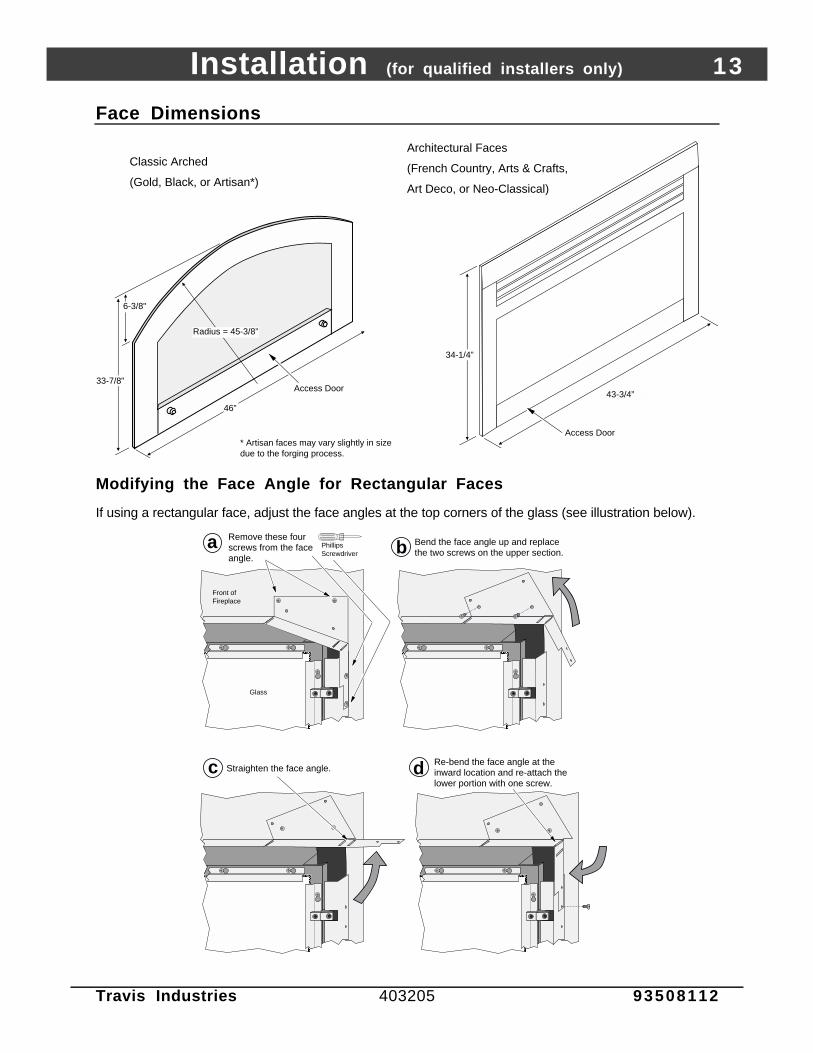
Face Dimensions
33-7/8"
6-3/8"
46”
Access Door
Radius = 45-3/8”
Classic Arched
(Gold, Black, or Artisan*)
* Artisan faces may vary slightly in size due to the forging process.
34-1/4”
43-3/4”
Access Door
Architectural Faces
(French Country, Arts & Crafts,
Art Deco, or Neo-Classical)
Modifying the Face Angle for Rectangular Faces
If using a rectangular face, adjust the face angles at the top corners of the glass (see illustration below).
AAAAAAAAAAAAAA
AAAAAAAAAAAA
Remove these four screws from the face angle.
Phillips Screwdriver
Bend the face angle up and replace the two screws on the upper section.
AAAAAAAAAAAAAA
AAAAAA
AAAAAAA
AAAAA
Re-bend the face angle at the inward location and re-attach the lower portion with one screw.
AAAAAAA
AAAAAAAAAA
Straighten the face angle.
ba
dc
Front of Fireplace
Glass
14 Installation (for qualified installers only)
Travis Industries 403205 93508112
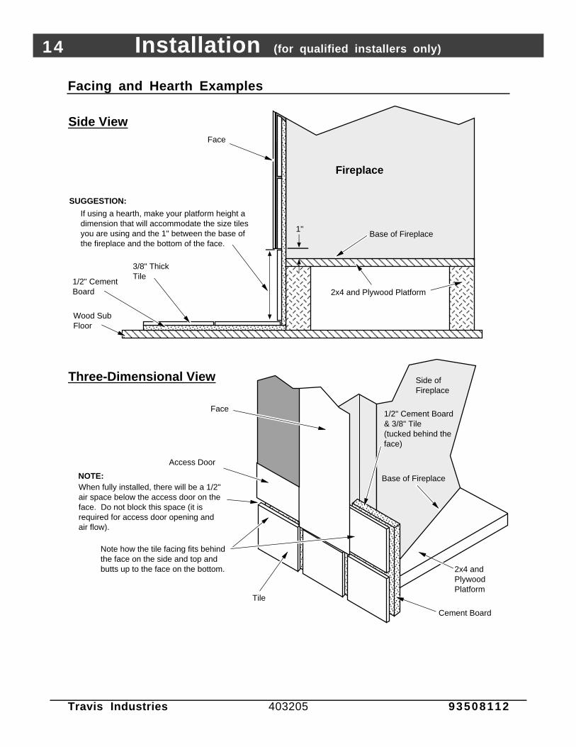
Facing and Hearth Examples
AAAAAAAA
AAAAAAAAAAAAAAAAA
AAAAAAAAAAAAAAAAAAAAAAAAAA
Fireplace
Face
3/8" Thick Tile
1/2" Cement Board
Wood Sub Floor
1"
Side View
AAAAAAAAAAAAAAAAAAAAAA
2x4 and Plywood Platform
Face
Side of Fireplace
AAAAAAAAAAAAAAAAAA
AAAAAAAAAAAAAAAAAAAAAAAAA
AAAAAAAAAAAAAAAAAAAAAAAAAAAAAAAAAAAAAAAAAA
Note how the tile facing fits behind the face on the side and top and butts up to the face on the bottom.
When fully installed, there will be a 1/2" air space below the access door on the face. Do not block this space (it is required for access door opening and air flow).
Three-Dimensional View
Tile
Cement Board
2x4 and Plywood Platform
If using a hearth, make your platform height a dimension that will accommodate the size tiles you are using and the 1" between the base of the fireplace and the bottom of the face.
SUGGESTION:
Base of Fireplace
Base of Fireplace
1/2" Cement Board & 3/8" Tile (tucked behind the face)
NOTE:
Access Door

Installation (for qualified installers only) 15
Travis Industries 403205 93508112
Facing and Hearth Examples (continued)
AAAAAAAAAAAAAAAAAAAAAAAAAA
FireplaceFace
3/8" Thick Tile
1/2" Cement Board
Wood Sub Floor
1"
AAAAAAA
1/2" Cement Board & 3/8" thick tile(tucked behind the face)
Side View
Three-Dimensional ViewFace
Side of Fireplace
Note how the tile facing fits behind the face on the side and top.
When hearth installation is correctly completed, there will be a 1/2" air space below the access door on the face. Do not block this air space (it is required for access door opening and proper air flow).
3/8" Tile
1/2" Cement Board
WARNING:
AAAAAAAAAAAAAAAAAAAAAAAAAAAAAAAA
AAAAAAAAAAAAAAAAAAAAAAAAAAAAAAAAAAAAAAAA
AAAAAAAAAAAAAAA
AAAAAAAAAAAA
Base of Fireplace
Base of Fireplace
There will be a 1/16" clearance between the finish face and the top of the tile on the hearth.
Wood Sub Floor
Do not install cement board underneath the fireplace. To do so would leave a large gap underneath the finish faceplate sides.
NOTE:
Access Door
16 Installation (for qualified installers only)
Travis Industries 403205 93508112
Mantel Requirements
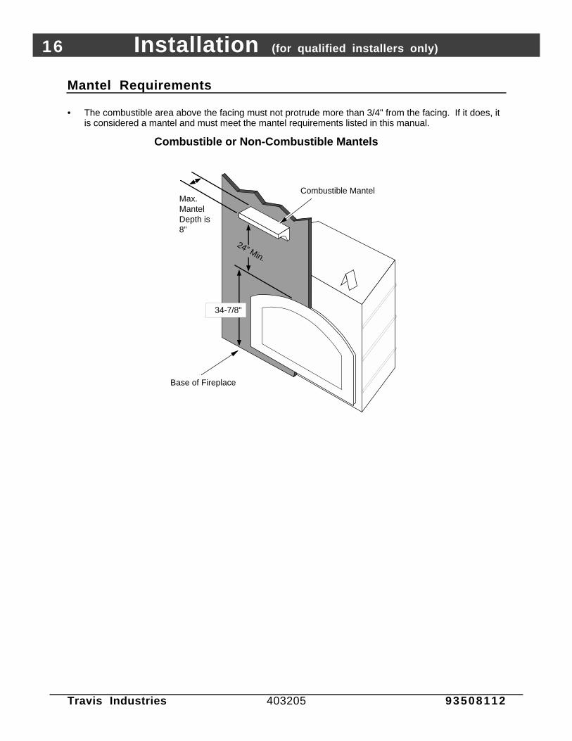
• The combustible area above the facing must not protrude more than 3/4" from the facing. If it does, itis considered a mantel and must meet the mantel requirements listed in this manual.
Combustible or Non-Combustible Mantels
Combustible Mantel
34-7/8"
24” Min.
Max.Mantel Depth is 8”
Base of Fireplace
Installation (for qualified installers only) 17
Travis Industries 403205 93508112
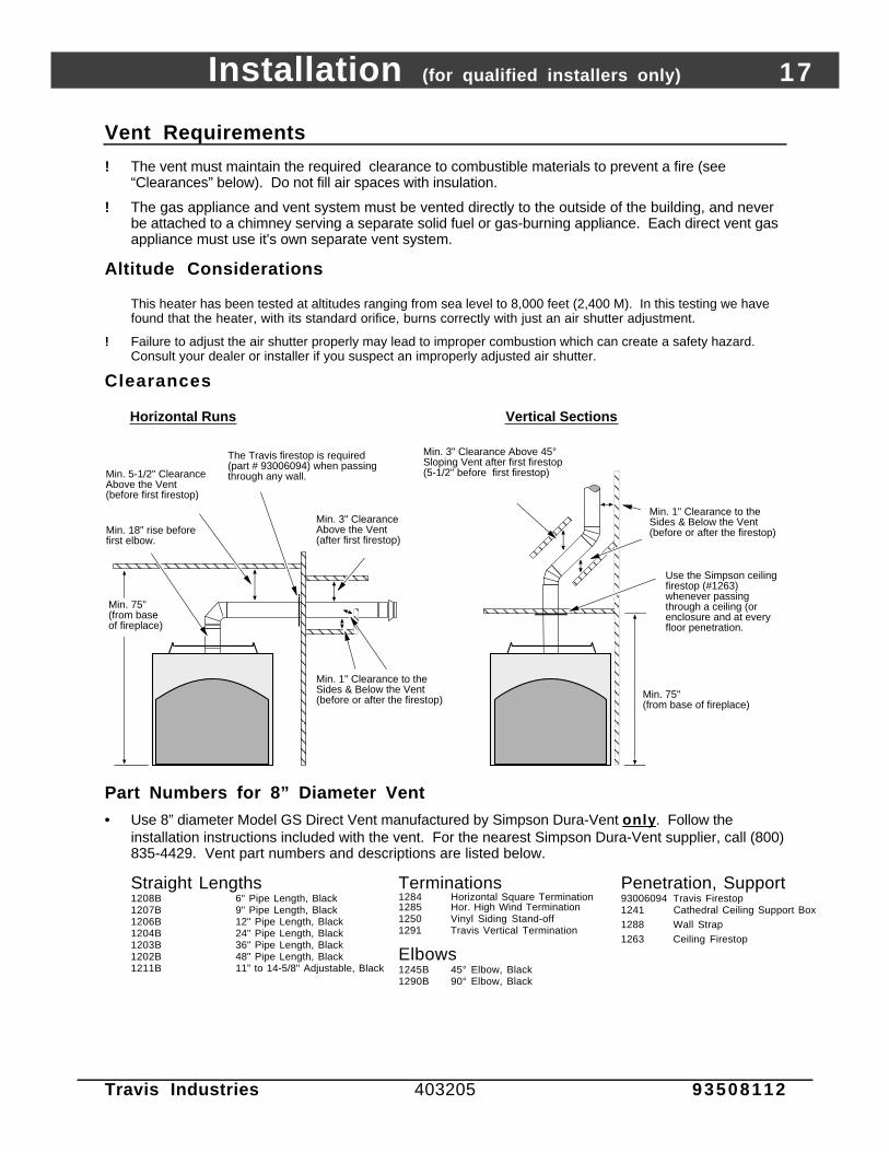
Vent Requirements
! The vent must maintain the required clearance to combustible materials to prevent a fire (see“Clearances” below). Do not fill air spaces with insulation.
! The gas appliance and vent system must be vented directly to the outside of the building, and neverbe attached to a chimney serving a separate solid fuel or gas-burning appliance. Each direct vent gasappliance must use it's own separate vent system.
Altitude Considerations
This heater has been tested at altitudes ranging from sea level to 8,000 feet (2,400 M). In this testing we havefound that the heater, with its standard orifice, burns correctly with just an air shutter adjustment.
! Failure to adjust the air shutter properly may lead to improper combustion which can create a safety hazard.Consult your dealer or installer if you suspect an improperly adjusted air shutter.
Clearances
Horizontal Runs
AAAAAAAAA
Vertical Sections
Min. 3" Clearance Above 45° Sloping Vent after first firestop (5-1/2" before first firestop)
AAAAAA
Min. 1" Clearance to the Sides & Below the Vent (before or after the firestop)
AAAAAAAAAAA
AAAAAA
AAA
The Travis firestop is required (part # 93006094) when passing through any wall.Min. 5-1/2" Clearance
Above the Vent (before first firestop)
Min. 3" Clearance Above the Vent (after first firestop)
AAAAAAAAAAAAA
AAAAAAAA
Min. 1" Clearance to the Sides & Below the Vent (before or after the firestop)
A
Min. 75" (from base of fireplace)
Min. 18" rise before first elbow.
Min. 75" (from base of fireplace)
Use the Simpson ceiling firestop (#1263) whenever passing through a ceiling (or enclosure and at every floor penetration.
Part Numbers for 8” Diameter Vent
• Use 8” diameter Model GS Direct Vent manufactured by Simpson Dura-Vent only . Follow theinstallation instructions included with the vent. For the nearest Simpson Dura-Vent supplier, call (800)835-4429. Vent part numbers and descriptions are listed below.
Straight Lengths1208B 6" Pipe Length, Black1207B 9" Pipe Length, Black1206B 12" Pipe Length, Black1204B 24" Pipe Length, Black1203B 36" Pipe Length, Black1202B 48" Pipe Length, Black1211B 11” to 14-5/8" Adjustable, Black
Terminations1284 Horizontal Square Termination1285 Hor. High Wind Termination1250 Vinyl Siding Stand-off1291 Travis Vertical Termination
Elbows1245B 45° Elbow, Black1290B 90° Elbow, Black
Penetration, Support93006094 Travis Firestop1241 Cathedral Ceiling Support Box1288 Wall Strap1263 Ceiling Firestop

18 Installation (for qualified installers only)
Travis Industries 403205 93508112
Vent Installation
• In addition to the requirements below, follow the requirements provided with the vent.
Vertical Termination (part # 1291)
Use a roof flashing and storm collar whenever passing through the roof
Vertical Vent Requirements
Horizontal Vent Requirements
Minimum framing for fire stop
Min. 1" Clearance on Horizontal Sections to combustible surfaces.
10"by10"
Use the Simpson ceiling firestop (#1263) whenever passing through a ceiling (or enclosure and at every floor penetration.
Combustible Framing
Use the Travis firestop (part # 93006094) when passing through a wall. NOTE: make sure the firestop is postitioned correctly so the 3" clearance is allowed above the vent.
3" Min.
1" Min.
1" Min.Combustible Surfaces
Minimum framing for fire stop
Minimum12" tall
Minimum10" wide
• Slide the vent sections together and turn 1/4 turn until the sections lock inplace.
• Screws are not required to secure the vent. However, three screws may beused to secure vent sections together if desired.
• High temperature sealant is recommended at the appliance starter sectionconnection (use high-temperature silicone or Mill-Pac®).
• If disassembly is required, at time of re-assembly check to see if the ventcreates a tight fit. If it does not, apply high temperature sealant to the joints ofthe affected sections.
• Horizontal sections require a 1/4" rise every 12" of travel
• Horizontal sections require non-combustible support every three feet (e.g.: plumbing tape)
Installation (for qualified installers only) 19
Travis Industries 403205 93508112
Approved Vent Configurations
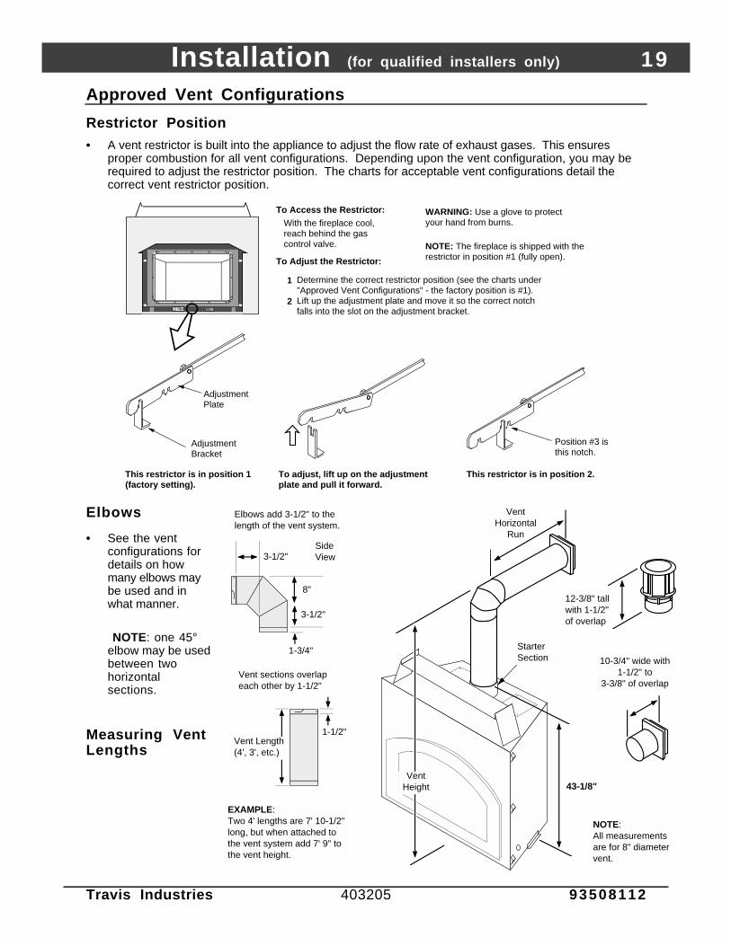
Restrictor Position
• A vent restrictor is built into the appliance to adjust the flow rate of exhaust gases. This ensuresproper combustion for all vent configurations. Depending upon the vent configuration, you may berequired to adjust the restrictor position. The charts for acceptable vent configurations detail thecorrect vent restrictor position.
With the fireplace cool, reach behind the gas control valve.
To Adjust the Restrictor:
To Access the Restrictor:
1
2
NOTE: The fireplace is shipped with the restrictor in position #1 (fully open).
Determine the correct restrictor position (see the charts under "Approved Vent Configurations" - the factory position is #1).Lift up the adjustment plate and move it so the correct notch falls into the slot on the adjustment bracket.
AAAAAAAAAAAAAAAAAAAA
This restrictor is in position 1 (factory setting).
This restrictor is in position 2.
Adjustment Bracket
Position #3 is this notch.
Adjustment Plate
To adjust, lift up on the adjustment plate and pull it forward.
WARNING: Use a glove to protect your hand from burns.
Elbows
• See the ventconfigurations fordetails on howmany elbows maybe used and inwhat manner.
NOTE: one 45°elbow may be usedbetween twohorizontalsections.
Measuring VentLengths
6-1/4"
NOTE:All measurements are for 8" diameter vent.
Vent Horizontal
Run
EXAMPLE:Two 4' lengths are 7' 10-1/2" long, but when attached to the vent system add 7' 9" to the vent height.
Vent Height
Elbows add 3-1/2" to the length of the vent system.
3-1/2"
Side View
1-3/4"
1-1/2"Vent Length(4', 3', etc.)
Vent sections overlap each other by 1-1/2"
43-1/8"
10-3/4" wide with 1-1/2" to
3-3/8" of overlap
Starter Section
12-3/8" tall with 1-1/2" of overlap
3-1/2"
8"
20 Installation (for qualified installers only)
Travis Industries 403205 93508112
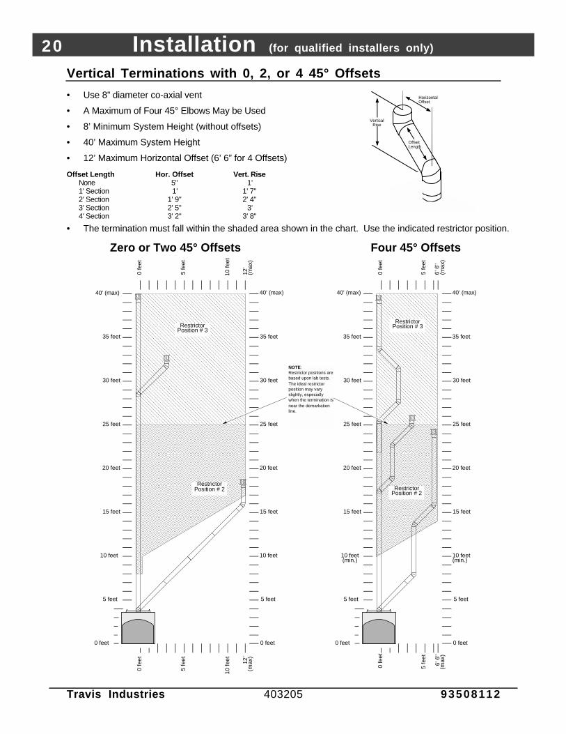
Vertical Terminations with 0, 2, or 4 45° Offsets
• Use 8” diameter co-axial vent
• A Maximum of Four 45° Elbows May be Used
• 8’ Minimum System Height (without offsets)
• 40’ Maximum System Height
• 12’ Maximum Horizontal Offset (6’ 6” for 4 Offsets)
Offset Length Hor. Offset Vert. RiseNone 5" 1'1' Section 1' 1' 7"2' Section 1' 9" 2' 4"3' Section 2' 5" 3'4' Section 3' 2" 3' 8"
Offset Length
Horizontal Offset
Vertical Rise
• The termination must fall within the shaded area shown in the chart. Use the indicated restrictor position.
AAAAAAAAAAAAAAAAAAAAAAAAAAAAAAAAAAAAAAAAAAAAAAAAAAAAAAAAAAAAAAAAAAAAAAAAAAAAAAAAAAAAAAAAAAAAAAAAAAAAAAAAAAAAAAAAAAAAAAAAAAAAAAAAAAAAAAAAAAAAAAAAAAAAAAAAAAAAAAAAAAAAAAAA
AAAAAAAAAAAAAAAAAAAAAAAAAAAAAAAAAAAAAAAAAAAAAAAAAAAAAAAAAAAAAAAAAAAAAAAAAAAAAAAAAAAAAAAAAAAAAAAAAAAAAAAAAAAAAAAAAAAAAAAAAAAAAAAAAAAAAAAAAAAAAAAAAAAAAAAAAAAAAAAAAAAAAAAAAAAAAAAAAAAA
AAAAAAAAAAAAAAAAAAAAAAAAAAAAAAAAAAAAAAAAAAAAAAAAAAAAAAAAAAAAAAAAAAAAAAAAAAAAAAAAAAAAAAAAAAAAAAAAAA
AAAAAAAAAAAAAAAAAAAAAAAAAAAAAAAAAAAAAAAAAAAAAAAAAAAAAAAAAAAAAAAAAAAAAAAAAAAAAAAAAAAAAAAAAAA
5 feet
10 feet(min.)
15 feet
20 feet
25 feet
30 feet
0 feet
35 feet
0 fe
et
5 fe
et
6' 6
" (m
ax)
5 feet
0 feet
0 fe
et
5 fe
et
6' 6
" (m
ax)
10 feet(min.)
15 feet
20 feet
25 feet
30 feet
35 feet
Four 45° Offsets
5 feet
10 feet
15 feet
20 feet
25 feet
30 feet
0 feet
40' (max)
0 fe
et
5 fe
et
5 feet
0 feet
0 fe
et
Restrictor Position # 2
Restrictor Position # 3
10 feet
15 feet
20 feet
30 feet
Zero or Two 45° Offsets
5 fe
et 12'
(max
)
NOTE:Restrictor positions are based upon lab tests. The ideal restrictor position may vary slightly, especially when the termination is near the demarkation line.
25 feet
10 fe
et
12'
(max
)
10 fe
et
Restrictor Position # 2
Restrictor Position # 3
35 feet 35 feet
40' (max) 40' (max) 40' (max)

Installation (for qualified installers only) 21
Travis Industries 403205 93508112
Horizontal Terminations with One Vertical Elbow
The termination must fall within the shaded area shown in the chart. Use the indicated restrictor position.
AAAAAAAAAAAAAAAAAAAAAAAAAAAAAAAAAAAAAAAAAAAAAAAAAAAAAAAAAAAAAAAAAAAAAAAAAAAAAAAAAAAAAAAAAAAAAAAAAAAAAAAAAAAAAAAAAAAAAAAAAAAAAAAAAAAAAAAAAAAAAAAAAAAAAAAAAAAAAAAAAAAAAAAAAAAAAAAAAAAAAAAAAAAAAAAAAAAAAAAAAAAAAAAAAAAAAAAAAAAAAAAAAAAAAAAAAAAAAAAAAAAAAAAAAAAAAAAAAAAAAAAAAAAAAAAAA
NOTE:
• One horizontal elbow (45° or 90°) is allowed (except in those configurations that lie in the region under "Restrictor Postion #1" below). The horizontal vent length is calculated by adding the length before and after the elbow (H1 + H2 = horizontal vent length).
• Horizontal sections require a 1/4" rise every 12" of travel.
• The maximum vertical height is 20'.
• The maximum horizontal length is 25'.
H1
Horizontal Elbow (45° or 90°)
Vertical Elbow
H2
AAAAAAAAAAAAAAAAAAAAAAAAAAAAAAAAAAAAAAAAAAAAAAAAAAAAAAAAAAAAAAAAAAAAAAAAAAAAAAAAAAAAAAAAAAAAAAAAAAAAAAAAA
5 feet
0 feet
0 fe
et
25' (
max
)
5 feet
0 fe
et
25' (
max
)
Restrictor Position #2
20' (max) 20' (max)
5 fe
et
10 fe
et
5 fe
et
10 fe
et
0 feet
15 fe
et
20 fe
et
10 feet
15 feet
15 fe
et
20 fe
et
10 feet
15 feet
No Horizontal Elbows Allowed
Restrictor Position #2
NOTE:Restrictor positions are based upon lab tests. The ideal restrictor position may vary slightly.
Min. 18" Rise Before First Elbow
Restrictor Position #1

22 Installation (for qualified installers only)
Travis Industries 403205 93508112
Horizontal Terminations with Three Vertical Elbows
The termination must fall within the shaded area shown in the chart. Use the indicated restrictor position.
NOTE: • A total of three elbows must be used.• No horizontal elbows may be used (a horizontal elbow is defined
as an elbow that directs the vent from a horizontal direction to another horizontal direction).
• Two 45° elbows may be substituted for two of the 90° elbows.• Horizontal sections require a 1/4" rise every 12" of travel.• The maximum vertical height is 19'.• The maximum horizontal length is 20'.
Horizontal Elbows are NOT ALLOWED
AAAAAAAAAAAAAAAAAAAAAAAAAAAAAAAAAAAAAAAAAAAAAAAAAAAAAAAAAAAAAAAAAAAAAAAAAAAAAAAAAAAAAAAAAAAAAAAAAAAAAAAAAAAAAAAAAAAAAAA
AAAAAAAAAAAAAAAAAAAAAAAAAAAAAAAAAAAAAAAAAAAAAAAAAAAAAAAAAAAAAAAAAAAAAAAAAAAAAAAAAAAAAAAAAAAAAAAAAAAAAA
5 feet
0 feet
0 fe
et
5 feet
0 fe
et
19' (max) 19' (max)
5 fe
et
10 fe
et
5 fe
et
10 fe
et
0 feet
15 fe
et
20' (
max
)
10 feet
15 feet
15 fe
et
20' (
max
)
10 feet
15 feet
Min. 24" Rise Before First Elbow
NOTE:Restrictor positions are based upon lab tests. The ideal restrictor position may vary slightly.
Restrictor Position #1
Restrictor Position #2

Installation (for qualified installers only) 23
Travis Industries 403205 93508112
Vertical Terminations with Two Vertical 90° Elbows
The termination must fall within the shaded area shown in the chart. Use the indicated restrictorposition.
AAAAAAAAAAAAAAAAAAAAAAAAAAAAAAAAAAAAAAAAAAAAAAAAAAAAAAAAAAAAAAAAAAAAAAAAAAAAAAAAAAAAAAAAAAAAAAAAAAAAAAAAAAAAAAAAAAAAAAAAAAAAAAAAAAAAAAAAAAAAAAAAAAAAAAAAAAAAAAAAAAAAAAAAAAAAAAAAAAAAAAAAAAAAAAAAAAAAAAAAAAAAAAAAAAAAAAAAAAAAAAAAAAAAAAAAAAAAAAAAAAAAAAAAAAAAAAAAAAAAAAAAAAAAAAAAAAAA
AAAAAAAAAAAAAAAAAAAAAAAAAAAAAAAAAAAAAAAAAAAAAAAAAAAAAAAAAAAA
AAAAAAAAAAAAAAAAAAAAAAAAAAAAAAAAAAAAAAAAAAAAAAAAAAAAAAAAAAAAAAAAAAAAAAAAAAAAAAAAAAAAAAAAAAAAAAAAAAAAAAAAAAAAAAAAAAAAAAAAAAAAAAAAAAAAAAAAAAAAAAAAAAAAAAAAAAAAAAAAAAAAAAAAAAAAAAAAAAAAAAAAAAAAAAAAAAAAAAAAAAAAAAAAAAAAAAAAAAAAAAAAAAAAAAAAAAAAAAAAAAAAAAAAAAAAAAAAAAAAAAAAAAAAAAAAAAAAAAAAAAAAAAAAAAAAAAAAAAAAAAAAAAAAAAAAAAAAAAAAAAAAAAAAAAAAAAAAAAAAAAAAA
5 feet
10 feet(min.)
15 feet
20 feet
25 feet
30 feet
0 feet
40' (max)
5 fe
et
10 fe
et
15 fe
et
0 fe
et
5 fe
et
10 fe
et
15 fe
et
20'(m
ax)
15 feet
20 feet
25 feet
30 feet
0 feet
0 fe
et
NOTE: Horizontal sections require a 1/4" rise every 12" of travel.
10 feet(min.)
40' (max)
20'(m
ax)
NOTE:Restrictor positions are based upon lab tests. The ideal restrictor position may vary slightly, especially when the termination is near a demarkation line.
5 feetNOTE: 2' minimum before first elbow.
NOTE: One 45° or 90° elbow may be used between horizontal sections. Horizontal length is caculated by adding each horizontal run together.
35 feet35 feet
Restrictor Position # 1
Restrictor Position # 2
Restrictor Position # 3

24 Installation (for qualified installers only)
Travis Industries 403205 93508112
Termination Requirements (see the illustration below)
! Venting terminals shall not be recessed into a wall or siding.
A Minimum 9" clearance from any door or window
B Minimum 12" above any grade, veranda, porch, deck or balcony
C Minimum 12" from outside corner walls
D Minimum 12" from inside corner walls
E Minimum 11" clearance below unventilated soffits or roof surfacesMinimum 18" clearance below ventilated soffitsMinimum 6" clearance from roof eavesNOTE: Vinyl surfaces require 24"
11” Min.
6” Min.
Roof Surface
Roof Eaves
F Minimum 18" clearance below a veranda, porch, deck or balcony (must have two open sides)
G Minimum 48" clearance from any adjacent building
H Minimum 84" clearance above any grade when adjacent to public walkways or drivewaysNOTE: may not be used over a walkway or driveway shared by an adjacent building
I Minimum 48" clearance from any mechanical air supply inlet, 72" for Canada
J Minimum 36" clearance above and 48” below and to the sides of non-mechanical air supply inlet
K Minimum 36" from the area above the meter/regulator (vent outlet)
L Minimum 36" from the meter/regulator (vent outlet)
M Minimum 12” above the roof line (for vertical terminations)
*Note: In Canada the vent termination must be a minimum 2' (.6 M) tall and 2' (.6 M)above any portion of the roof within 10' (3 M) of the vent.
N Minimum 24” horizontal clearance to any surface (such as an exterior wall) – for vertical terminations
C
B
H
E
G A
DF
L
K J
I
NOTE: Measure clearances to the nearest edge of the exhaust hood.
AE
E
M
N
• Use the vinyl siding standoff (#1250) when installing on an exterior with vinyl siding.
• Vent termination must not be located where it will become plugged by snow or other material
• These clearances meet UMC-1994 and the CNA/CGA-B149 code standards.

Installation (for qualified installers only) 25
Travis Industries 403205 93508112
Gas Line Requirements
! The gas line must be installed in accordance with all local codes, if any; if not, follow ANSI 223.1 andthe requirements listed below.
! The fireplace and gas control valve must be disconnected from the gas supply piping during anypressure testing of that system at test pressures in excess of 1/2 psig. For pressures under 1/2 psig,isolate the gas supply piping by closing the manual shutoff valve.
! Leak test all gas line joints and the gas control valve prior to and after starting the fireplace.
Fuel
• This fireplace is designed either for natural gas or for propane (but not for both). Check thesticker on the top of the gas control valve to make sure the correct fuel is used.
Gas Line Connection
• A manual shutoff valve is required for installation (within 3’ of the heater or inside the fireplace).T-Handle gas cocks are required in Massachusetts in compliance with code 248CMR.
Gas Control Valve
3/8" M.P.T to 1/2" O.D. Fitting (Factory installed)
The 1" diameter access hole is located 2-3/8" above the base of the fireplace. Cut an "X" in the gasket covering the inlet and insert the gas line through the gasket.
If the gas line is routed from the right side, bend the flex tube 180°.
10" Flex Tube (shipped with the fireplace - min. bending radius is 3/4")
A shutoff valve may be placed within the fireplace
The included fitting accepts a 3/8" M.P.T. or
1/2" F.P.T.
-- OR --
-- OR --
18-1/2"
6-1/2" 6-3/4"
Gas Inlet Pressure:
Standard Input Pressure
Natural Gas 7" W.C. (1.74 kPA)
Propane 13" W.C. (2.73 kPA)
• If the pressure is not sufficient, make sure the piping used is large enough, the supply regulator isadequately adjusted, and the total gas load for the residence does not exceed the amount supplied.
• The supply regulator (the regulator that attaches directly to the residence inlet or to the propane tank)should supply gas at the suggested input pressure listed above. Contact the local gas supplier if theregulator is at an improper pressure.

26 Installation (for qualified installers only)
Travis Industries 403205 93508112
Electrical Connection
! Make sure the household breaker is shut off prior to working on any electrical lines.
! The appliance, when installed, must be electrically grounded in accordance with local codes or, in theabsence of local codes, with the National Electrical Code, ANSI NFPA 70, or the Canadian ElectricalCode, CSA C22.1.
• The electrical line must be 14 gauge, and supply 120 Volts at 60 Hz (2 Amps)
1 Follow the directions below to connect power to the fireplace.
6-1/4"
a bInsert the sheathed cable from the power source through this cable clamp. Once the wires are attached, tighten the clamp to secure the cable.
Replace the cover removed in step "a".
Attach the common (white), ground (exposed or green) wires, and hot (black) wires from the power source to the electrical connector (included with the fireplace). Then attach the connector to the fireplace.
c
dStandard Screwdriver
Remove the cover from the fireplace junction box.
1/4"
Nut
driv
er
Electrical Connector (shipped in the fireplace behind the cover plate)WARNING: Make sure power is
off from the power lead before conducting any wiring.
NOTE:If using the power heat duct, you may wish to route the wiring for it at this point. See the instructions under "Optional Equipment".
Finalizing the Installation (for qualified installers only) 27
Travis Industries 403205 93508112
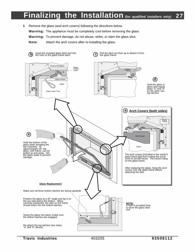
1 Remove the glass (and arch covers) following the directions below.
Warning: The appliance must be completely cool before removing the glass.
Warning: To prevent damage, do not abuse, strike, or slam the glass shut.
Note : Attach the arch covers after re-installing the glass.
Insert the included glass latch tool into the hole on the glass frame latch.b c Pull the latch out then up to detach it from
the glass frame.
Hold the glass in place and repeat steps "a" and "b" for the other two top latches.
d
Hold the bottom of the glass while swinging the top outwards. At approximately 45° the glass, with frame, can be pulled up and away. Set the glass aside to prevent damage.
Glass Replacement
Make sure all three bottom latches are facing upwards
Position the glass at a 45° angle and lay it on the two tabs below the firebox. When correctly positioned, the tabs on the frame should insert into the bottom latches.
Swing the glass into place (make sure the bottom latches are engaged.
Re-attach the top latches (see steps "a" and "b" above).
Arch Cover
After replacing the glass, hang the arch covers over the glass frame before attaching the face.
Glass
The arch covers (included in the owner's pack) block light from exiting the scroll work on arched faces. The covers hang on the glass frame.
Glass Frame
Arch Covers (both sides)
Front of Fireplace
Glass
Glass Frame
Glass Frame Latch
Glass Latch Tool
NOTE:A hole is provided here to store the glass latch tool.
a
e

28 Finalizing the Installation (for qualified installers only)
Travis Industries 403205 93508112
? If converting this unit to propane, do so now (see the instructions on page 46).
2 Install the rock wool, log set, kibbles, and embers (if using the decorative fireback, install it prior to thelog set - page 57).
Warning: Failure to position the parts in accordance with these diagrams or failure to use only partsspecifically approved with this appliance may result in property damage or personal injury.
Note: If you have converted this appliance to propane (LP), the front burner air shutter mayrequire adjustment. The front air shutter is adjusted with the logs removed.
(a) Rock Wool Installation
Place small pieces of rock wool directly over the burner holes on the front burner.
Preparing the Rock Wool:
The rock wool comes in one clump. Tear off “dime” sized clumps and flatten them out. The wool glows best when very thin and porous.
AAAAAA
(b) Rear Log Installation (has a #1 stamped on bottom)
Place the rear log diagonally so this notch fits against the air deflector. Push the log all the way back.
TOP VIEW
Finalizing the Installation (for qualified installers only) 29
Travis Industries 403205 93508112
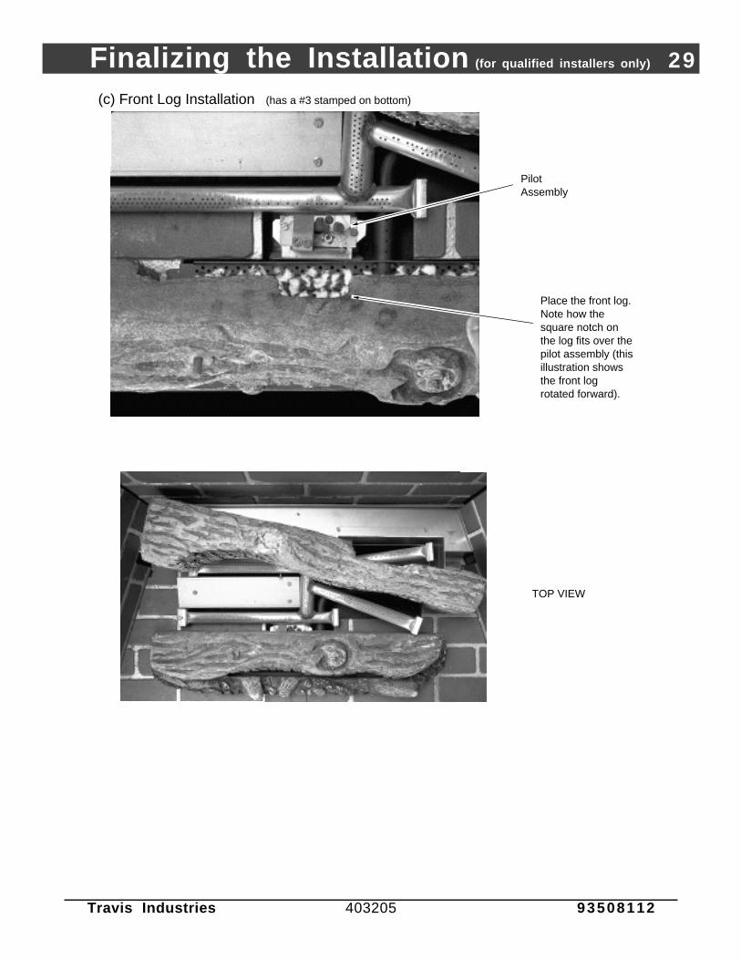
(c) Front Log Installation (has a #3 stamped on bottom)
TOP VIEW
Place the front log. Note how the square notch on the log fits over the pilot assembly (thisillustration shows the front log rotated forward).
Pilot Assembly

30 Finalizing the Installation (for qualified installers only)
Travis Industries 403205 93508112
(d) Left Log Installation (has a #2 stamped on bottom)
enter the left og on this edge. Slide the og all the way o the right.
OP VIEW
Finalizing the Installation (for qualified installers only) 31
Travis Industries 403205 93508112
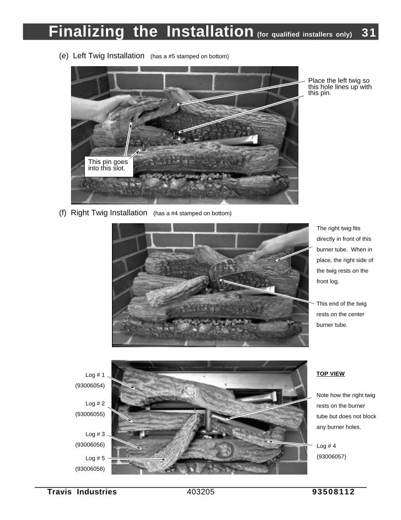
(e) Left Twig Installation (has a #5 stamped on bottom)
Place the left twig so this hole lines up with this pin.
This pin goes into this slot.
(f) Right Twig Installation (has a #4 stamped on bottom)
TOP VIEW
The right twig fits
directly in front of this
burner tube. When in
place, the right side of
the twig rests on the
front log.
This end of the twig
rests on the center
burner tube.
Note how the right twig
rests on the burner
tube but does not block
any burner holes.
Log # 1
(93006054)
Log # 2
(93006055)
Log # 3
(93006056) Log # 4
(93006057)Log # 5
(93006058)
32 Finalizing the Installation (for qualified installers only)
Travis Industries 403205 93508112
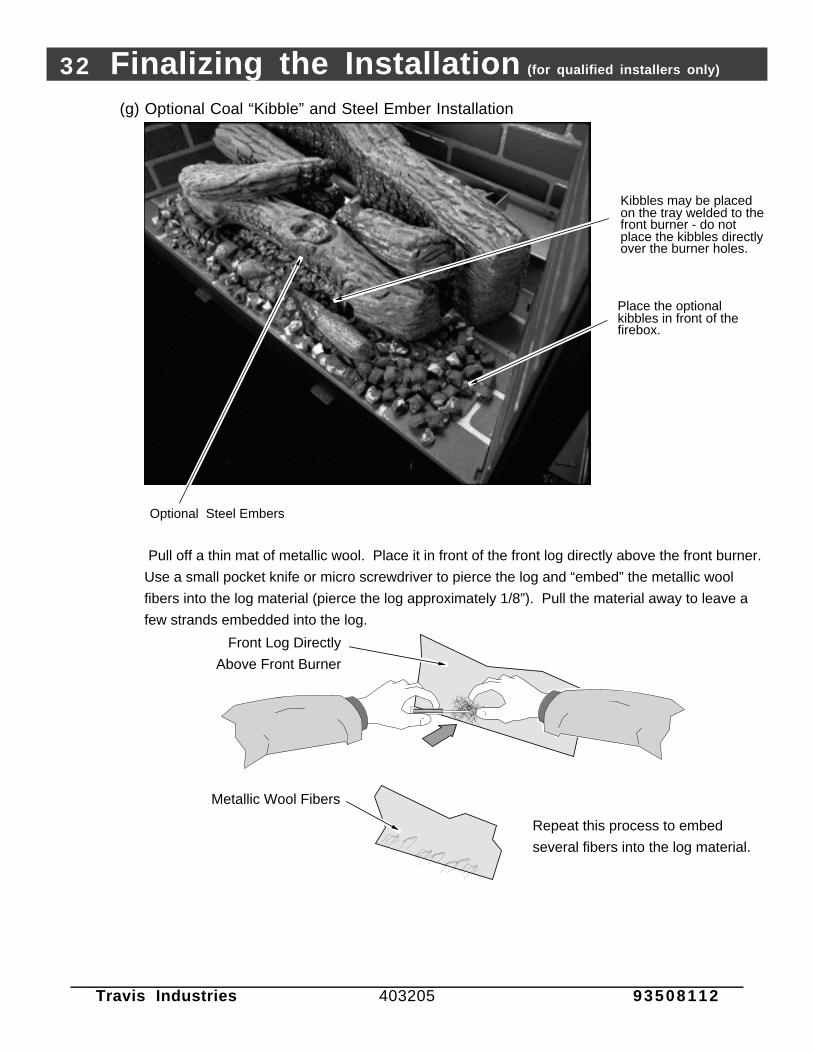
(g) Optional Coal “Kibble” and Steel Ember Installation
Place the optional kibbles in front of the firebox.
Optional Steel Embers
Kibbles may be placed on the tray welded to the front burner - do not place the kibbles directly over the burner holes.
Repeat this process to embed
several fibers into the log material.
AAAAAAAAA
AAAAAA
Front Log Directly
Above Front Burner
Metallic Wool Fibers
Pull off a thin mat of metallic wool. Place it in front of the front log directly above the front burner.
Use a small pocket knife or micro screwdriver to pierce the log and “embed” the metallic wool
fibers into the log material (pierce the log approximately 1/8”). Pull the material away to leave a
few strands embedded into the log.

Finalizing the Installation (for qualified installers only) 33
Travis Industries 403205 93508112
! We recommend you purge the gas line at this time (with the glass removed). This allows gas to bedetected once it enters the firebox, ensuring gas does not build up.
3 Replace the glass (and arch covers when using arched faces - see page 27).
4 Turn on the gas to the fireplace. Turn on gas to the heater. Leak test all gas joints prior to starting theappliance. Start the pilot (see page 37). Start the main burner. Leak test all gas joints again.
5 Check the pilot flame to make sure it looks like the illustration below. Adjust the pilot flame ifnecessary.
Standard Screwdriver
The pilot flame must contact the thermocouple and
thermopile (see the illustration below). Adjust the pilot up or
down as necessary.
To adjust the pilot flame, turn this screw (NOTE: if totally
unscrewed gas will come out of this port). Clockwise
lowers the flame while counter-clockwise raises it.
6 Let the heater burn for fifteen minutes. Adjust the rear air shutter, if necessary, to achieve the correctlooking flame (see the illustration below).
• The air shutter adjusts the amount of air that mixes with the gas before it exits the burner holes. It isused to fine-tune the flame for differences in altitude and vent configuration.
Control Panel
NOTE: If the air control is all the way open, yet the flames remain sooty, shut off gas to the fireplace and contact a qualified gas service technician.
Correct
Flames should be blue at the base, yellow-orange on the top.
If the flames are over 14" tall or sooty on the ends, open the air shutter.
Not Enough Air
If the flames are all blue and short, close the air shutter.
Too Much Air
NOTE: The logs must be installed correctly to monitor the flame while adjusting the air shutter.
Air Shutter Control
Loosen the nut on the air shutter control. Move the control left or right until the flame looks correct. Pushing to the right gives the flame less air (making it more orange). Pushing to the left gives the flame more air, making it more blue.
3/8" Nutdriver
ON
OFFMA
IN B
UR
NE
R
PILOT IGNITER
BLOWER CONTROL
LO
OFFHI
There are two air shutters on this model:
Main Burner (rear)
! If the air shutter is in its fully open position, yet the flames remain sooty, shut off gas to the heater andcontact your Travis Industries Dealer for a remedy.
34 Finalizing the Installation (for qualified installers only)
Travis Industries 403205 93508112
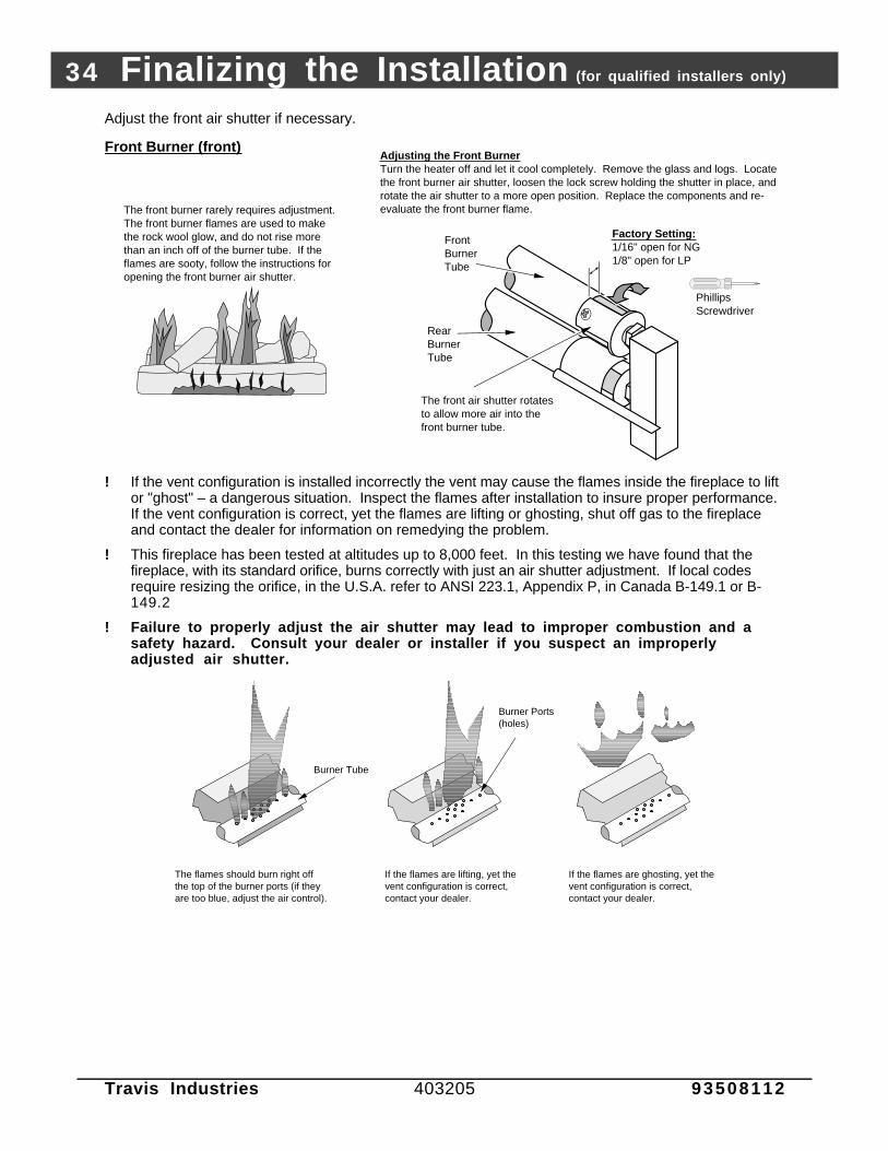
Adjust the front air shutter if necessary.
Front Burner (front)
The front burner rarely requires adjustment. The front burner flames are used to make the rock wool glow, and do not rise more than an inch off of the burner tube. If the flames are sooty, follow the instructions for opening the front burner air shutter.
Adjusting the Front BurnerTurn the heater off and let it cool completely. Remove the glass and logs. Locate the front burner air shutter, loosen the lock screw holding the shutter in place, and rotate the air shutter to a more open position. Replace the components and re-evaluate the front burner flame.
Phillips Screwdriver
Factory Setting:1/16" open for NG1/8" open for LP
The front air shutter rotates to allow more air into the front burner tube.
Front Burner Tube
Rear Burner Tube
! If the vent configuration is installed incorrectly the vent may cause the flames inside the fireplace to liftor "ghost" – a dangerous situation. Inspect the flames after installation to insure proper performance.If the vent configuration is correct, yet the flames are lifting or ghosting, shut off gas to the fireplaceand contact the dealer for information on remedying the problem.
! This fireplace has been tested at altitudes up to 8,000 feet. In this testing we have found that thefireplace, with its standard orifice, burns correctly with just an air shutter adjustment. If local codesrequire resizing the orifice, in the U.S.A. refer to ANSI 223.1, Appendix P, in Canada B-149.1 or B-149.2
! Failure to properly adjust the air shutter may lead to improper combustion and asafety hazard. Consult your dealer or installer if you suspect an improperlyadjusted air shutter.
The flames should burn right off the top of the burner ports (if they are too blue, adjust the air control).
If the flames are lifting, yet the vent configuration is correct, contact your dealer.
Burner Tube
Burner Ports (holes)
If the flames are ghosting, yet the vent configuration is correct, contact your dealer.
Finalizing the Installation (for qualified installers only) 35
Travis Industries 403205 93508112
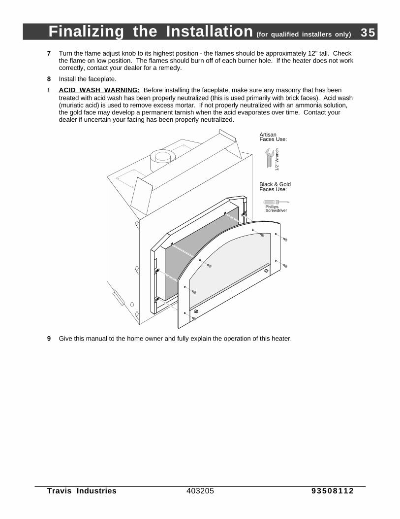
7 Turn the flame adjust knob to its highest position - the flames should be approximately 12" tall. Checkthe flame on low position. The flames should burn off of each burner hole. If the heater does not workcorrectly, contact your dealer for a remedy.
8 Install the faceplate.
! ACID WASH WARNING : Before installing the faceplate, make sure any masonry that has beentreated with acid wash has been properly neutralized (this is used primarily with brick faces). Acid wash(muriatic acid) is used to remove excess mortar. If not properly neutralized with an ammonia solution,the gold face may develop a permanent tarnish when the acid evaporates over time. Contact yourdealer if uncertain your facing has been properly neutralized.
Phillips Screwdriver
6-1/4"
1/2"
Wre
nch
Black & Gold Faces Use:
Artisan Faces Use:
9 Give this manual to the home owner and fully explain the operation of this heater.

36 Operation
Travis Industries 403205 93508112
Before You Begin
Warning: Read this entire manual before you use your new fireplace (especially the section "SafetyPrecautions" on pages 2 & 3). Failure to follow the instructions may result in propertydamage, bodily injury, or even death.
Warning: Do not operate appliance with the glass front removed, cracked or broken. Replacement ofthe glass should be done by a licensed or qualified service person.
Location of Controls - See explanation below
AAAAAAAA
AAAAAAAAA
AAAAAAAAA
Gas Control Valve
Gas Control KnobFlame Adjust Knob
An instruction card for operating the fireplace is attached to the inside of the fireplace here. Replace it for easy reference.
The pilot flame is located below the front log.
ON
OFFMA
IN B
UR
NE
R
On/Off Switch
PILOT IGNITER
Pilot Igniter
BLOWER CONTROL
OFF
Blower Knob
HI
Open the access door to view the controls.
LO
Blower Knob This knob controls the speed of the internal convection blower that pushesthe heated air into the room.
On/Off Switch This control is used to turn the fireplace on and off.
Pilot Igniter The pilot igniter is used only to start the pilot. When pressed, it sends anelectrical charge to the pilot assembly. This creates a blue spark directly nextto the pilot, igniting the pilot flame.
Gas Control Knob This knob controls gas to the stove and pilot. There are three positions: ON,OFF, and PILOT. The indicator line is to the left of the knob.
Flame Adjust Knob This knob controls the flame height from low ("LO") to high ("HI”). Theindicator line is above the knob.
? If using a remote control or thermostat, the On/Off Switch must be left "ON". Turning the On/OffSwitch "OFF" will keep the fireplace off always.

Operation 37
Travis Industries 403205 93508112
Starting The Pilot Flame
The pilot flame is required to ignite the mainburners (it also plays a safety role). It should beleft on once lit. It will stay lit unless the gascontrol valve is turned to "OFF". However, thepilot will go out if the gas is shut off, thepropane tank runs out (or low) or if the stovemalfunctions. If the pilot turns off frequently,call your dealer for information. To start thepilot follow the directions below:
WARNING :When lighting or re-lighting thepilot, the glass must be removed(see page 27).
a Remove the glass (see page 27 for details).
b Push the gas control knob in slightly and turnit to the "OFF" position. The knob will notturn from "ON" to "OFF" unless the knob isdepressed slightly. Wait five minutes to letany gas that may have accumulated insidethe firebox escape. If you smell leaking gas,follow the directions on the cover "IF YOUSMELL GAS".
c Turn the gas control knob to the "PILOT"position and press the knob in, this will allowgas to flow to the pilot light. Press thebutton on the pilot igniter repeatedly untilyou see the pilot light.
WARNING:If the pilot does not light after 15seconds, release the knob and callyour dealer for service. Do notattempt to light pilot until servicehas been performed.
NOTE:You may wish to remove the log setto gain a better view of the pilot (seepage 28).
d Keep the gas control knob depressed for 30seconds once it is lit.
e Release the gas control knob. If the pilotgoes out, repeat step C. If the pilot refusesto stay lit, call your dealer for service. Withthe pilot lit, proceed to step “f”.
f Replace the glass.
g Turn the gas control knob counter-clockwiseto "ON". The pilot is now lit and the heatercan be turned on and off.
AAAAAAAA
AAAA
30 seconds
PILOT IGNITER
a
b
AAAAAAAA
AAAA
5 minutes
c
d
e
f
g
?
38 Operation
Travis Industries 403205 93508112
Starting the Fireplace for the First Time
+ Burn the heater at a high setting with the blower off for an extended period (up to 48 hours). This willcure the painted surfaces. Fumes from the paint curing and oil burning off the steel will occur. This isnormal. We recommend opening a window to vent the room.
+ Dust may accumulate inside the convection area of the heater when left idle. Once the heater is re-started, a “smoky” smell may be created (similar to a baseboard heater when it is re-started).
+ Condensation may appear on the glass each time you start the fireplace - this is normal.
+ Blue Flames will occur on the fireplace when it first comes on. After fifteen minutes the flames willturn a more realistic yellow and orange color.
? Certain installations use a remote "wall switch" to turn the fireplace on and off. If this is the case, leavethe ON/OFF switch "ON".
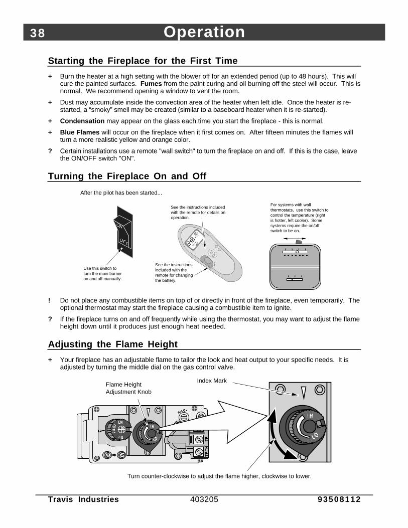
Turning the Fireplace On and Off
OFF
ROO
M T
EMP
°F°F
SET TE
MP
TIM
ER
MIN
Tim
eSet
Tim
eCan
cel
Au
to
OFF
ON
Use this switch to turn the main burner on and off manually.
After the pilot has been started...
See the instructions included with the remote for details on operation.
For systems with wall thermostats, use this switch to control the temperature (right is hotter, left cooler). Some systems require the on/off switch to be on.
See the instructions included with the remote for changing the battery.
! Do not place any combustible items on top of or directly in front of the fireplace, even temporarily. Theoptional thermostat may start the fireplace causing a combustible item to ignite.
? If the fireplace turns on and off frequently while using the thermostat, you may want to adjust the flameheight down until it produces just enough heat needed.
Adjusting the Flame Height
+ Your fireplace has an adjustable flame to tailor the look and heat output to your specific needs. It isadjusted by turning the middle dial on the gas control valve.
Flame Height Adjustment Knob
Index Mark
Turn counter-clockwise to adjust the flame higher, clockwise to lower.
Operation 39
Travis Industries 403205 93508112
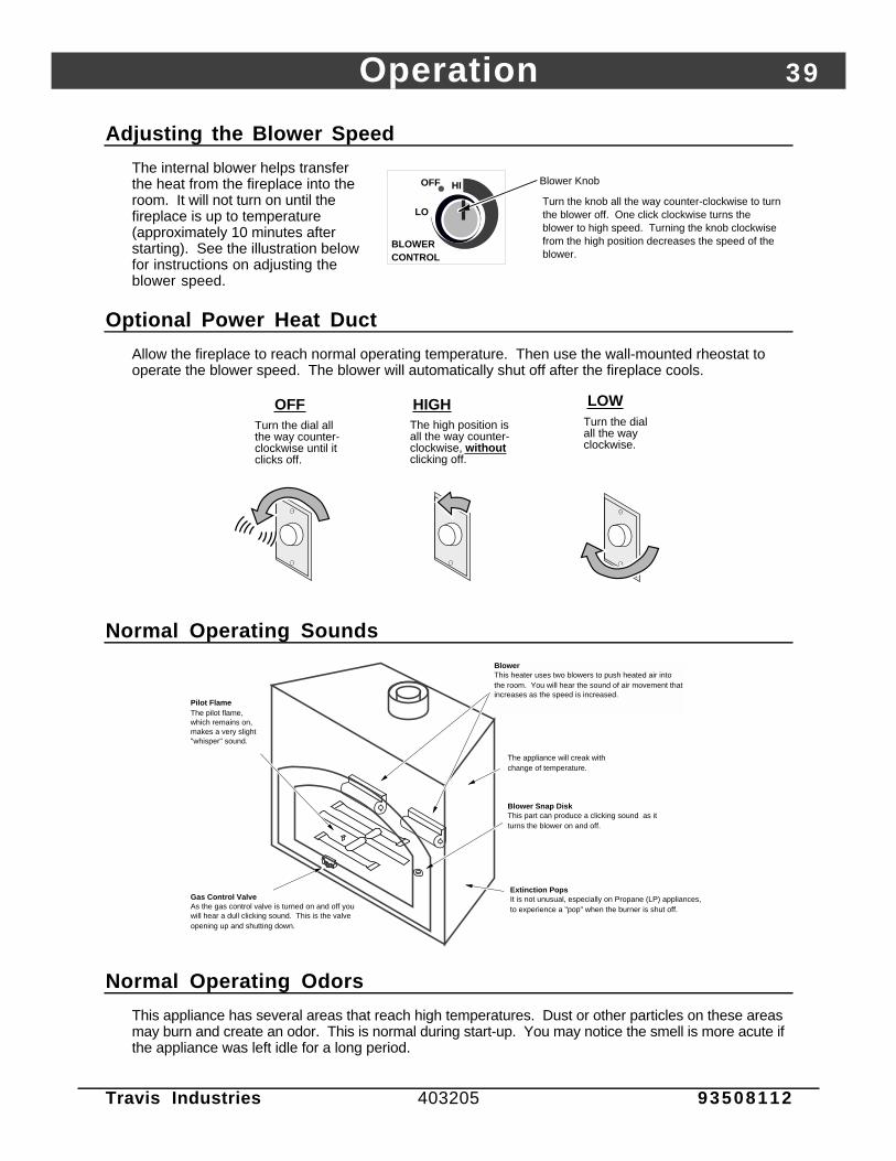
Adjusting the Blower Speed
The internal blower helps transferthe heat from the fireplace into theroom. It will not turn on until thefireplace is up to temperature(approximately 10 minutes afterstarting). See the illustration belowfor instructions on adjusting theblower speed.
BLOWER CONTROL
LO
OFF HI Blower Knob
Turn the knob all the way counter-clockwise to turn the blower off. One click clockwise turns the blower to high speed. Turning the knob clockwise from the high position decreases the speed of the blower.
Optional Power Heat Duct
Allow the fireplace to reach normal operating temperature. Then use the wall-mounted rheostat tooperate the blower speed. The blower will automatically shut off after the fireplace cools.
OFFTurn the dial all the way counter-clockwise until it clicks off.
HIGHThe high position is all the way counter-clockwise, without clicking off.
LOWTurn the dial all the way clockwise.
Normal Operating Sounds
Gas Control ValveAs the gas control valve is turned on and off you will hear a dull clicking sound. This is the valve opening up and shutting down.
Blower Snap Disk This part can produce a clicking sound as it turns the blower on and off.
The appliance will creak with change of temperature.
Pilot FlameThe pilot flame, which remains on, makes a very slight "whisper" sound.
Blower This heater uses two blowers to push heated air into the room. You will hear the sound of air movement that increases as the speed is increased.
Extinction Pops It is not unusual, especially on Propane (LP) appliances, to experience a "pop" when the burner is shut off.
Normal Operating Odors
This appliance has several areas that reach high temperatures. Dust or other particles on these areasmay burn and create an odor. This is normal during start-up. You may notice the smell is more acute ifthe appliance was left idle for a long period.

40 Maintenance (for qualified service personnel only)
Travis Industries 403205 93508112
Maintaining Your Fireplace's Appearance! Fingerprints or other marks left on the optional gold surface may become etched in place if they are not wiped
clean prior to turning the heater on. Clean gold with denatured alcohol and a soft cloth (make sure the fireplace iscool). Other cleaners may leave a film that may become etched into the gold.
• Clean the glass with soap and water (do not use abrasive cleaners). To remove the glass, follow the instructionson page 27.
Yearly Service Procedure
! Failure to inspect and maintain the fireplace may lead to improper combustion and a potentially dangeroussituation. The following procedures must be done by a qualified technician.
1 Check the pilot flame. It should touch approximately 3/8" of the top of the thermopile and touch the top of thethermocouple (see illustration below). If it does not, contact your dealer for service.
2 Shut off gas to the fireplace by turning the gas control knob to "OFF" (see step A under "Starting the Pilot" onpage 37). Let the fireplace cool for 15 minutes. Remove the faceplate (see instructions included with face) andglass (see page 27).
3 Remove the log set (NOTE: the logs are very fragile - see page 28). If severely deteriorated, replace.Check the logs for sooting. A small amount of soot along the bottom of the logs is normal. If excessive sootingis found, the fireplace will require adjustment. Contact your dealer.
4 Clean the burner tube (especially the burner holes) and inspect the following:• Check the burner for cracked holes, warpage, or corrosion.• Check the firebox and area around the pilot to make sure there is no warping or damage.• If any problem is found, discontinue use and contact your dealer for service.
AAAAAA
AAAAAAAAA
AAAAAAA
Check the burner holes.
Make sure the burners
are not warped or
damaged.
Check the walls and ceiling of the firebox for
deterioration.
Before Disassembly: Check the pilot flame.
It should touch the thermopile and
thermocouple.
Thermopile
Pilot HoodThermocouple
5 Replace the log set. Replace the glass (if the glass is damaged, replace it). Make sure the gasket along theperimeter of the glass contacts the face of the firebox and forms an air-tight seal. If it does not, re-align orreplace the gasket to insure an air-tight seal. Replace the faceplate.
6 Inspect the area behind the access door. Clean if necessary. Check the gas control valve and the gas lines. Ifany damage is found, discontinue use and contact your dealer for service. Clean the air channels and ducts.
7 Start the pilot and turn on the main burner. The flames should be orange/yellow and not touch the top of thefirebox. If the pilot or main burners do not burn correctly, contact your dealer for service. Monitor the bloweroperation.
8 Inspect the glass. If damage is found, replace the glass (with frame) with Travis Industries glass assembly(glass installation is on page 27).
9 Remove any debris or vegetation near the vent termination. Contact your dealer if any sooting or deterioration isfound near the vent termination.
1 0 Inspect the vent sections. If any sections are disconnected or require replacement, make sure to seal bothinner and outer sections of pipe and secure the sections together with three sheet metal screws.
Maintenance (for qualified service personnel only) 41
Travis Industries 403205 93508112
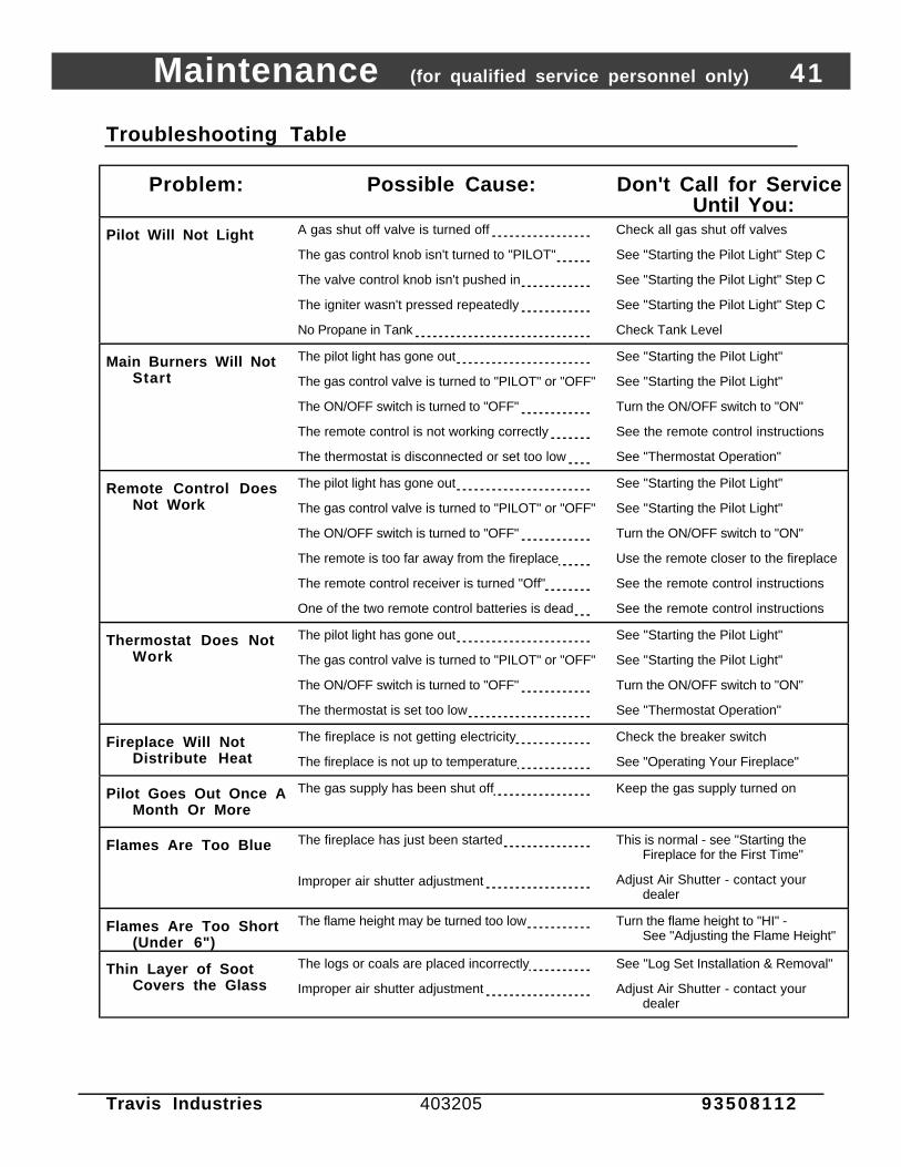
Troubleshooting Table
Problem: Possible Cause: Don't Call for ServiceUntil You:
Pilot Will Not Light A gas shut off valve is turned off
The gas control knob isn't turned to "PILOT"
The valve control knob isn't pushed in
The igniter wasn't pressed repeatedly
No Propane in Tank
Check all gas shut off valves
See "Starting the Pilot Light" Step C
See "Starting the Pilot Light" Step C
See "Starting the Pilot Light" Step C
Check Tank Level
Main Burners Will NotStart
The pilot light has gone out
The gas control valve is turned to "PILOT" or "OFF"
The ON/OFF switch is turned to "OFF"
The remote control is not working correctly
The thermostat is disconnected or set too low
See "Starting the Pilot Light"
See "Starting the Pilot Light"
Turn the ON/OFF switch to "ON"
See the remote control instructions
See "Thermostat Operation"
Remote Control DoesNot Work
The pilot light has gone out
The gas control valve is turned to "PILOT" or "OFF"
The ON/OFF switch is turned to "OFF"
The remote is too far away from the fireplace
The remote control receiver is turned "Off"
One of the two remote control batteries is dead
See "Starting the Pilot Light"
See "Starting the Pilot Light"
Turn the ON/OFF switch to "ON"
Use the remote closer to the fireplace
See the remote control instructions
See the remote control instructions
Thermostat Does NotWork
The pilot light has gone out
The gas control valve is turned to "PILOT" or "OFF"
The ON/OFF switch is turned to "OFF"
The thermostat is set too low
See "Starting the Pilot Light"
See "Starting the Pilot Light"
Turn the ON/OFF switch to "ON"
See "Thermostat Operation"
Fireplace Will NotDistribute Heat
The fireplace is not getting electricity
The fireplace is not up to temperature
Check the breaker switch
See "Operating Your Fireplace"
Pilot Goes Out Once AMonth Or More
The gas supply has been shut off Keep the gas supply turned on
Flames Are Too Blue The fireplace has just been started
Improper air shutter adjustment
This is normal - see "Starting theFireplace for the First Time"
Adjust Air Shutter - contact yourdealer
Flames Are Too Short(Under 6")
The flame height may be turned too low Turn the flame height to "HI" -See "Adjusting the Flame Height"
Thin Layer of SootCovers the Glass
The logs or coals are placed incorrectly
Improper air shutter adjustment
See "Log Set Installation & Removal"
Adjust Air Shutter - contact yourdealer
42 Maintenance (for qualified service personnel only)
Travis Industries 403205 93508112
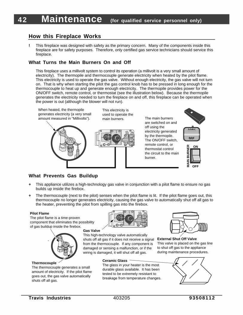
How this Fireplace Works
! This fireplace was designed with safety as the primary concern. Many of the components inside thisfireplace are for safety purposes. Therefore, only certified gas service technicians should service thisfireplace.
What Turns the Main Burners On and Off
This fireplace uses a millivolt system to control its operation (a millivolt is a very small amount ofelectricity). The thermopile and thermocouple generate electricity when heated by the pilot flame.This electricity is used to operate the gas valve. Without enough electricity, the gas valve will not turnon. That is why when starting the pilot the gas control knob has to be pressed in long enough for thethermocouple to heat up and generate enough electricity. The thermopile provides power for theON/OFF switch, remote control, or thermostat (see the illustration below). Because the thermopilegenerates the electricity needed to turn the fireplace on and off, this fireplace can be operated whenthe power is out (although the blower will not run).
When heated, the thermopile generates electricity (a very small amount measured in "Millivolts").
This electricity is used to operate the main burners. The main burners
are switched on and off using the electricity generated by the thermopile. The ON/OFF switch, remote control, or thermostat control the circuit to the main burner.
ON
OFFMA
IN B
UR
NE
R
What Prevents Gas Buildup
+ This appliance utilizes a high-technology gas valve in conjunction with a pilot flame to ensure no gasbuilds up inside the firebox.
+ The thermocouple (next to the pilot) senses when the pilot flame is lit. If the pilot flame goes out, thisthermocouple no longer generates electricity, causing the gas valve to automatically shut off all gas tothe heater, preventing the pilot from spilling gas into the firebox.
Ceramic GlassThe glass in your heater is the most durable glass available. It has been tested to be extremely resistant to breakage from temperature changes.
Gas ValveThis high-technology valve automatically shuts off all gas if it does not receive a signal from the thermocouple. If any component is damaged or sensing a malfunction, or if the wiring is damaged, it will shut off all gas.
Pilot FlameThe pilot flame is a time-proven component that eliminates the possibility of gas buildup inside the firebox.
ThermocoupleThe thermocouple generates a small amount of electricity. If the pilot flame goes out, the gas valve automatically shuts off all gas.
External Shut Off ValveThis valve is placed on the gas line to shut off gas to the appliance during maintenance procedures.
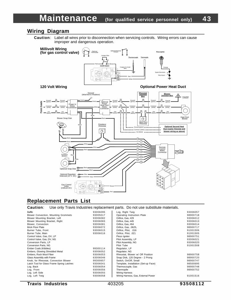
Maintenance (for qualified service personnel only) 43
Travis Industries 403205 93508112
Wiring DiagramCaution: Label all wires prior to disconnection when servicing controls. Wiring errors can cause
improper and dangerous operation.
Fireplace Blowers
Rheostat Junction
Box
Hot (black)
Common (white)
Ground (green)
Blower Snap Disk
Optional Power
Heat Duct Molex
Connector
Power In Molex
Connector
Hot (black)
Common (white)
Ground (green)
Hot (black)
Common (white)
Ground (green)
Heat Duct Rheostat
Hot (black)
Common (white)
Ground (green)
Hot (black)
Common (white)
Ground (green)
Grounded to Blower
Po
wer
Su
pp
ly
Hot (black)
Common (white)
Ground (green)
Heat Duct Blower
Blower Junction Box
Optional Second Heat Duct (same rheostat and blower wiring as above)
120 Volt Wiring
Fireplace Rheostat
Ground (attached to fireplace)
Green
White
White
Green
Black
Black
Optional Power Heat Duct
Millivolt Wiring (for gas control valve)
Black
Orange
White
Piezo Igniter
Thermopile
Red
AA
Thermocouple
Copper Co-Axial Wire
Red
Optional Thermostat
Optional Remote Control
Spark Electrode
Pilot Hood
On/Off Switch
Jumper Wire
Brown
7
Hot (black)
Common (white)
Ground (green)
1
35
7
24
68
9
1211
10
79
Blue
Blue
Optional Regulator Solenoid (24 V. DC)
Red
BrownGas Control
Valve (millivolt DC)
White
Black
Black
BlackOptional Snap Disk
3
69 Remote
Control Molex
Connector
14
11
8
25
White
Black
Black
White
Replacement Parts ListCaution: Use only Travis Industries replacement parts. Do not use substitute materials.Baffle 93006095 Log, Right Twig 93006057Blower Convection, Mounting Grommets 93005017 Operating Instruction Plate 98900718Blower Mounting Bracket, Left 93006082 Orifice, Gas, #29 93006012Blower Mounting Bracket, Right 93006083 Orifice, Gas, #45 93006013Blower, Convection 93006081 Orifice, Gas, #64 93006014Brick Floor Plate 93006072 Orifice, Gas, .0625, 98900717Burner Tube, Front 93006015 Orifice, Pilot, .016 91001506Burner Tube, Main 93006016 Orifice, Pilot, .021 91001505Control Valve, Gas, DV, LP Piezo Igniter 98900751Control Valve, Gas, DV, NG Pilot Assembly, LP 93006021Conversion Parts, LP Pilot Assembly, NG 93006020Conversion Parts, NG Pilot Tube 91001508Ember Coals (Kibbles) 99300114 Regulator, LPEmbers, Glowing Shredded Metal 93006052 Regulator, NGEmbers, Rock Wool Fiber 93006053 Rheostat, Blower w/ Off Position 98900758Glass Assembly with Frame 63006046 Snap Disk, 120 Degree - 2 Prong 98900720Knob, for Rheostat, Convection Blower 99300657 Switch, On/Off, Small 98900747Latch Tool for Glass Frame Spring Latches 93006041 Template, Installation (Set-up Face) 98500695Log, Back 93006054 Thermocouple, Gas 98900748Log, Front 93006056 Thermopile 98900752Log, Left Side 93006055 Wiring HarnessLog, Left Twig 93006058 Wiring Harness, Gas, External Power 91001516

44 Safety Label
Travis Industries 403205 93508112
The safety (listing) label is on a plate chained to the gas control valve. A copy of the safety label isshown below.
Warranty 45
Travis Industries 403205 93508112
To register your TRAVIS INDUSTRIES, INC. 7 Year Warranty, complete the enclosed warranty card and mail it within ten (10) days of the appliancepurchase date to: TRAVIS INDUSTRIES, INC., 10850 117th Place N.E., Kirkland, Washington 98033. TRAVIS INDUSTRIES, INC. warrants this gasappliance (appliance is defined as the equipment manufactured by Travis Industries, Inc.) to be defect-free in material and workmanship to the originalpurchaser from the date of purchase as follows:
Years 1 & 2 - COVERAGE: PARTS & LABOR
Burner Assembly:Burner, Burner Pan, Air Shutter Assembly, Main BurnerOrifice
Firebox Assembly:Adjustable Air Restrictor, Pressure Relief Mechanisms,Barometric Control Mechanism (for models with Remote HeatDucts), Glass Attachment Mechanism
Electrical Assembly (within heater structure): Blower, wiring harness, snap discs, rheostat speed control
Gold & Nickel PlatingFace & Door (see “Conditions and Exclusions” # 9)
Gas Control AssemblyAdjustable control valve, millivolt wiring and connectors (located withinthe metal heater structure), thermopile, thermocouple, pilot hood,orifices, pilot gas line, piezo ignitor
Ceramic GlassGlass (breakage from thermal shock)
Ceramic LogsLog Set, Coals, Ember Strip (Steel Fiber)
AccessoriesCast Brick, Cast Firebacks, Power Heat Ducts, Andirons
Convection Heat Exchanger
Re-Installation AllowanceIn cases where heater must be removed from home forrepairs, a partial cost of re-installation is covered (pre-authorization required)
One-Way Freight AllowanceOne-way freight allowance on pre-authorized repair done atfactory is covered.
Exclusions: Paint, Gasketing
Years 3 THROUGH 5 - COVERAGE: PARTS & LABOR
Burner Assembly:Burner, Burner Pan, Air Shutter Assembly, Main BurnerOrifice
Convection Heat Exchanger
Firebox Assembly:Adjustable Air Restrictor, Pressure Relief Mechanisms,Barometric Control Mechanism (for models withRemote Heat Ducts), Glass Attachment Mechanism
One-Way Freight AllowanceOne-way freight allowance on pre-authorized repair done atfactory is covered.
Exclusions: Paint, Gasketing, Electrical Assembly, Gas Control Assembly, Ceramic Glass, Ceramic Logs, Gold & Nickel Plating, Accessories,Re-Installation Allowance
Years 6 & 7 - COVERAGE: PARTS ONLY
Burner Assembly:Burner Tubes, Burner Pan, Air ShutterAssembly, Main Burner Orifice
Firebox Assembly:Adjustable Air Restrictor, Pressure Relief Mechanisms, Barometric Control Mechanism (formodels with Remote Heat Ducts), Glass Attachment Mechanism
Exclusions: Paint, Gasketing, Electrical Assembly, Gas Control Assembly, Ceramic Glass, Ceramic Logs, Gold & Nickel Plating, Accessories,Convection Heat Exchanger, Re-Installation Allowance, One-Way Freight Allowance, Labor
CONDITIONS & EXCLUSIONS1. This new gas appliance must be installed by a qualified gas appliance technician. It must be installed, operated, and maintained at all times in accordance with the instructions in the Owner’s
Manual. Any alteration, willful abuse, accident, neglect, or misuse of the product shall nullify this warranty.2. This warranty is nontransferable, and is made to the ORIGINAL purchaser, provided that the purchase was made through an authorized TRAVIS dealer.3. Discoloration and some minor expansion, contraction, or movement of certain parts and resulting noise, is normal and not a defect and, therefore, not covered under warranty. The installer
must ensure the appliance is burning as per the rating tag at the time of installation. Over-firing (operation above the listed BTU rate) of this appliance can cause serious damage and will nullifythis warranty.
4. The warranty, as outlined within this document, does not apply to the chimney components or other Non-Travis accessories used in conjunction with the installation of this product. If in doubt asto the extent of this warranty, contact your authorized TRAVIS retailer before installation.
5. Travis Industries will not be responsible for inadequate performance caused by environmental conditions such as nearby trees, buildings, roof tops, wind, hills or mountains or negative pressureor other influences from mechanical systems such as furnaces, fans, clothes dryers, etc.
6. This Warranty is void if:a. The unit has been operated in atmospheres contaminated by chlorine, fluorine or other damaging chemicals.b. The unit is subject to submersion in water or prolonged periods of dampness or condensation.c. Any damage to the unit, combustion chamber, heat exchanger or other components due to water, or weather damage which is the result of, but not limited to, improper chimney/venting
installation.7. Exclusions to this 7 Year Warranty include: injury, loss of use, damage, failure to function due to accident, negligence, misuse, improper installation, alteration or adjustment of the
manufacturer's settings of components, lack of proper and regular maintenance, damage incurred while the appliance is in transit, alteration, or act of God.8. This 7 Year warranty excludes damage caused by normal wear and tear, such as paint discoloration or chipping, worn or torn gasketing, corroded or cracked logs, embers, etc. Also excluded is
damage to the unit caused by abuse, improper installation, modification of the unit, drilling of the orifices, or the use of fuel other than that for which the unit is configured. Units are shipped fornatural gas and must be converted to propane using the included conversion kit. Confirm fuel configuration with your installer.
9. Damage to gold or nickel surfaces caused by fingerprints, scratches, melted items , or other external sources left on the gold or nickel from the use of cleaners other than denatured alcohol isnot covered in this warranty.
10. TRAVIS INDUSTRIES, INC. is free of liability for any damages caused by the appliance, as well as inconvenience expenses and materials. Incidental or consequential damages are not coveredby this warranty. In some states, the exclusion of incidental or consequential damage may not apply.
11. This warranty does not cover any loss or damage incurred by the use or removal of any component or apparatus to or from the gas appliance without the express written permission of TRAVISINDUSTRIES, INC. and bearing a TRAVIS INDUSTRIES, INC. label of approval.
12. Any statement or representation of TRAVIS products and their performance contained in TRAVIS advertising, packaging literature, or printed material is not part of this 7 year warranty.13. This warranty is automatically voided if the appliance’s serial number has been removed or altered in any way. If the appliance is used for commercial purposes, it is excluded from this warranty.14. No dealer, distributor, or similar person has the authority to represent or warrant TRAVIS products beyond the terms contained within this warranty. TRAVIS INDUSTRIES, INC. assumes no
liability for such warranties or representations.15. Travis Industries will not cover the cost of the removal or re-installation of hearths, facing, mantels, venting or other components.16. If for any reason any section of this warranty is declared invalid, the balance of the warranty remains in effect and all other clauses shall remain in effect.17. THIS 7 YEAR WARRANTY IS THE ONLY WARRANTY SUPPLIED BY TRAVIS INDUSTRIES, INC., THE MANUFACTURER OF THE APPLIANCE. ALL OTHER WARRANTIES,
WHETHER EXPRESS OR IMPLIED, ARE HEREBY EXPRESSLY DISCLAIMED AND PURCHASER’S RECOURSE IS EXPRESSLY LIMITED TO THE WARRANTIES SET FORTHHEREIN.
IF WARRANTY SERVICE IS NEEDED:1. If you discover a problem that you believe is covered by this warranty, you MUST REPORT it to your TRAVIS dealer WITHIN 30 DAYS, giving them proof of purchase, the purchase date,
and the model name and serial number.2. Travis Industries has the option of either repairing or replacing the defective component.3. If your dealer is unable to repair your appliance’s defect, he may process a warranty claim through TRAVIS INDUSTRIES, INC., including the name of the dealership where you purchased the
appliance, a copy of your receipt showing the date of the appliance’s purchase, and the serial number on your appliance. At that time, you may be asked to ship your appliance, freight chargesprepaid, to TRAVIS INDUSTRIES, INC. TRAVIS INDUSTRIES, INC., at its option, will repair or replace, free of charge, your TRAVIS appliance if it is found to be defective in material orworkmanship within the time frame stated within this 7 year warranty. TRAVIS INDUSTRIES, INC. will return your appliance, freight charges (years 1 to 5) prepaid by TRAVIS INDUSTRIES,INC., to your regional distributor, or dealership.
4. Check with your dealer in advance for any costs to you, when arranging a warranty call. Dealers may require you to pay a service or trip charges for any warranty work. This charge can varyfrom store to store.

46 Optional Equipment (for qualified installers only)
Travis Industries 403205 93508112
LP Conversion Instructions
Install the conversionkit prior to installingthe gas line toensure proper gasuse .
1 Remove the glass (seepage 27). Remove thelogs and rock wool (ifinstalled - page 28)
2 Remove the burner (seeillustration to the right).
AAAAAAAAAAAAAAAAAAAAAAAAAAAAAAAAAAAAAAAAAAAAAAAAAAAAAAAAAAAAAAAAAAAAAAAAAAAAAAAAAAAAAAAAAAAAAAAAAAAAAAAAAAAAAAAAAAAAAAAAAAAAAAAAAAAAAAAAAAAAAAAAAAAAAAAAAAAAAAAA
AAAAAAAAAAAAAAAAAA
AAAAAAAAAAAAAAAAAAAAAA
AAAAAAAAAAAAAAAAAAAAAAAAAAAAAAAAAAAAAAAAAAAAAAAAAA
AAAAAAAAAAAAAAAAAAAAAAAAAAAAAAAAAAAAAAAA
Remove the four screws holding the front and main burner in place.
1/4" Nutdriver
Air Control Slider
Slide the main burner to the left and lift it up and away from the firebox.
a
b
c
Slide the front burner to the left, lift it up slightly, and pull it forward.
AAAAAAAAAAAAAAAAAAAAAAAAAAAAAAAAAAAAAAAAAAAAAAAAAAAAAAAAAAAAAAAAAAAAAAAAAAAAAAAAAAAAAAAAAAAAAAAAAAAAAAAAAAAAAAAAAAAAAAAAAAAAAAAAAAAAAAAAAAAAAAAAAAAAAAAAAAAAAAAA
AAAAAAAAAAAAAAA
AAAAAAAAAAAA
AAAAAAAAAAAAAAAAAAAAAAAAAAAAAAAAAAAAAAAAAAAAAAAAAAAAAAAAAAAA
AAAAAAAAAAAAAAAAAAAAAAAAAAAAAAAAAAAAAAAAAAAAAAAAAAAAAA
Front Burner
NOTE: Loosen the air shutter control (see page 34) and slide the air shutter all the way to the right to aid in removal of the rear burner.
Burner Orifices
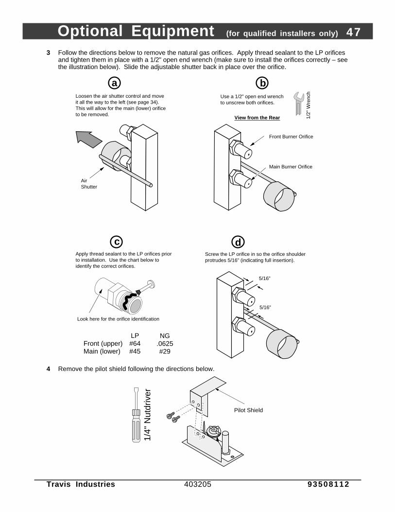
Optional Equipment (for qualified installers only) 47
Travis Industries 403205 93508112
3 Follow the directions below to remove the natural gas orifices. Apply thread sealant to the LP orificesand tighten them in place with a 1/2" open end wrench (make sure to install the orifices correctly – seethe illustration below). Slide the adjustable shutter back in place over the orifice.
Loosen the air shutter control and move it all the way to the left (see page 34). This will allow for the main (lower) orifice to be removed.
Air Shutter
Look here for the orifice identification
Apply thread sealant to the LP orifices prior to installation. Use the chart below to identify the correct orifices.
1/2"
Wre
nch
Use a 1/2” open end wrench to unscrew both orifices.
Front Burner Orifice
Main Burner Orifice
View from the Rear
Screw the LP orifice in so the orifice shoulder protrudes 5/16” (indicating full insertion).
5/16”
5/16”
d
a b
c
Front (upper)Main (lower)
LP#64#45
NG.0625#29
4 Remove the pilot shield following the directions below.
1/4"
Nut
driv
er
Pilot Shield
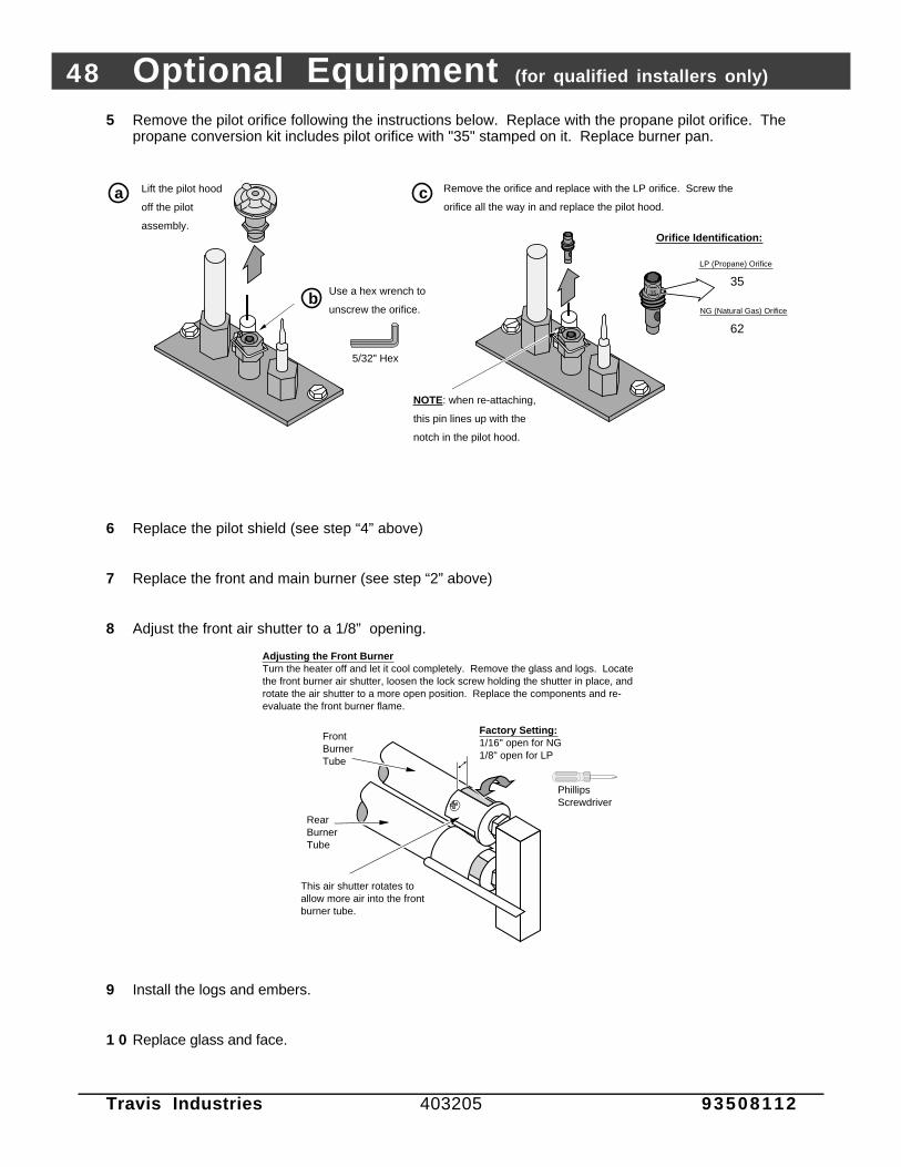
48 Optional Equipment (for qualified installers only)
Travis Industries 403205 93508112
5 Remove the pilot orifice following the instructions below. Replace with the propane pilot orifice. Thepropane conversion kit includes pilot orifice with "35" stamped on it. Replace burner pan.
Lift the pilot hood
off the pilot
assembly.
5/32" Hex
Use a hex wrench to
unscrew the orifice.
Remove the orifice and replace with the LP orifice. Screw the
orifice all the way in and replace the pilot hood.
LP (Propane) Orifice
Orifice Identification:
NG (Natural Gas) Orifice
35
62
35
a
b
c
NOTE: when re-attaching,
this pin lines up with the
notch in the pilot hood.
6 Replace the pilot shield (see step “4” above)
7 Replace the front and main burner (see step “2” above)
8 Adjust the front air shutter to a 1/8” opening.
Adjusting the Front BurnerTurn the heater off and let it cool completely. Remove the glass and logs. Locate the front burner air shutter, loosen the lock screw holding the shutter in place, and rotate the air shutter to a more open position. Replace the components and re-evaluate the front burner flame.
Phillips Screwdriver
Factory Setting:1/16" open for NG1/8" open for LP
This air shutter rotates to allow more air into the front burner tube.
Front Burner Tube
Rear Burner Tube
9 Install the logs and embers.
1 0 Replace glass and face.

Optional Equipment (for qualified installers only) 49
Travis Industries 403205 93508112
1 1 Remove the regulator from the front of the gas control valve. Replace with the propane regulator,using the new gasket and screws included with the regulator. NOTE: Leak test this area afterthe heater is installed, gas is connected, and the main burner is lit.
Place the LP
label on the base
of the fireplace
near the gas
control valve.
d
Remove and discard the three
screws using a slotted screwdriver
of Torx T-20.
NOTE: Make sure the
regulator gasket is correctly
aligned before installation.
Remove and discard the
regulator, diaphram, spring
and center post.
a
bSlotted Screwdriver(or T-20 Torx)
Install the LP regulator. Use
the screws included with the
LP regulator. Tighten to
approximately 25 Lbs. torque.
c
Slotted Screwdriver(or T-20 Torx)
1 2 Make the gas line connection, start the heater and thoroughly leak-test all gas connections and theregulator. Check the pilot. Adjust if necessary.
Standard Screwdriver
The pilot flame must contact the thermocouple and
thermopile (see the illustration below). Adjust the pilot up or
down as necessary.
To adjust the pilot flame, turn this screw (NOTE: if totally
unscrewed gas will come out of this port). Clockwise
lowers the flame while counter-clockwise raises it.
1 3 Inspect the flames. Adjust the air shutter if necessary (see step 7 on page 34).

50 Optional Equipment (for qualified installers only)
Travis Industries 403205 93508112
POWER HEAT DUCT (part # 98500769)
The optional heat duct allows the fireplace to transfer heat to separate locations in the home. One ortwo ducts may be used . Installation should take place prior to installing drywall.
Warning: This kit must be installed as specified in these instructions. Do not modify anycomponent.
Warning: Use of any external blower other than the Travis Power Heat Duct Blower will void thewarranty and listing of this appliance and may create a fire hazard.
Note : The power heat duct must be installed by a qualified service technician.
Note : Some building codesmay require the use offirestop spacerswhenever the ductpasses from room toroom.
Note : When routing ductsthrough a cold area(e.g. crawl space) werecommend insulatingthe duct with fiberglassinsulation. If paper-backed insulation isused, the paper can notcontact the duct.
Electrical Source
Starter Ring
Use 10” x 3-1/4” wall stack (duct) when passing through tight areas.
6" Duct
Duct Adapter (6” Round to 10” x 3-1/4”)
Floor Boot
Grill
Rheostat (with cover plate)
Junction Box
Wall Adapter (for use on 2 x 4 walls)
Heat Duct Electrical Wiring
Blower Box
Maximum Duct Length = 20'
1 Determine the route for the heat duct using the illustration below as a guide.
AAAA
AAA
A
AAAAAAAAAAAA
AAAAAAAAAAAAAA
AAA
AAAAAAAAAAAAAA
AAAAAAAAAAAAAAAAAAAAAAAAAAAA
AAAAAAAA
AAAAAAAAAAAAAAAA
AAAAAAAAAAAAAAAAAAAAAAAAAAAAAAAAAAAAAA
AAAAAAAAAAAAAAAAAAA
AAAAAAAAAAAAAAAAAAAA
AA
AAAAAAAAAAAAAAAAAA
AAAAAAAAAAAAAAAAAAAAAAAAAAAAAAAAAAAAAAAAAAAA
AAAAAAAAAAAAAAAAAAAAAAAAAAAAAAAAAAAAAAAAAAAAAAAAAAAAAAAAAAAAAAAAAAAAAAAAAAAAAAAAAAAAAAAAAAAAAAAAAAAA
Use 10” x 3-1/4” wall stack (duct) when passing through tight areas.
20’ Maximum Length
Duct Adapter (6” Round to 10” x 3-1/4” - included with the power heat vent kit)
Blower Box
0” Clearance to CombustiblesCo-Axial Vent
(for intake air and exhaust)
NOTE: Air flow through the duct is affected by length and number of bends. Keep the length and number of bends to the minimum to maximize performance.
When the duct penetrates the fireplace enclosure vertically and the top of the enclosure is within 36” of the top of the fireplace, a firestop spacer that maintains a 1/2” clearance between all sides of the duct and any combustible material must be used.
AAAAAAAA1/2”

Optional Equipment (for qualified installers only) 51
Travis Industries 403205 93508112
2 Attach the blower box to the framing or floorboards of the home following the instructions below.
Wall or Ceiling Mounting
bAttach the wall mounting brackets to the blower box.
Mount the bracket to these holes for 2 x 4 walls
Mount the bracket to these holes for 2 x 6 walls
Cut a hole between wall framing members for the blower assembly.
a
AAAAAAAAAAAA
AAAAAAAAAA
AAAAAAAAAA
AAAAAAAAAA
5-1/4" 16"*
* This blower was designed for framing on 16" centers - construct additional framing if needed.
c Slide the blower, with wires, into the hole cut in step "a". Attach with four screws.
AAAAAAAAAAAA
AAAAA
AAAAAAAAAA
AAAAAAAAAA
Floor Mounting
Cut a hole between floor joists for the blower box.
AAAAAAAAAAAAAAA
AAAAAAAAAAAAAAA
AA
5-1/4"14"
a b
c
Attach the floor boot to the blower box with the included screws.
Slide the blower into the hole cut in step "a". Attach with four screws.
AAAAAAAAAAAA
AAAAAAAAAAAA
AA
The screws attach to either of these pairs of holes. Use the upper pair for thick flooring, the lower pair for thin flooring.
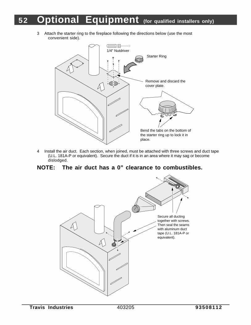
52 Optional Equipment (for qualified installers only)
Travis Industries 403205 93508112
3 Attach the starter ring to the fireplace following the directions below (use the mostconvenient side).
Bend the tabs on the bottom of the starter ring up to lock it in place.
1/4" Nutdriver
Remove and discard the cover plate.
Starter Ring
4 Install the air duct. Each section, when joined, must be attached with three screws and duct tape(U.L. 181A-P or equivalent). Secure the duct if it is in an area where it may sag or becomedislodged.
NOTE: The air duct has a 0” clearance to combustibles.
Secure all ducting together with screws. Then seal the seams with aluminum duct tape (U.L. 181A-P or equivalent).

Optional Equipment (for qualified installers only) 53
Travis Industries 403205 93508112
5 Attach the grill (and wall adapter, if necessary).
Grill
Wall Adapter (for use when the blower box protrudes from the wall - primarily on 2 x 4 walls)
AAAAAA
AAAAAA
AAAAAAAAAA
AAAAAAAAAA
Phillips Screwdriver
Screws (included with this kit)
WIRING DIAGRAM
Warning: All wiring should be done by a qualified electrician and shall be in compliance with localcodes and with the current National Electric Code ANSI/NFPA 70 (in the U.S.), or with thecurrent CSC22.1 Canadian Electric Code (in Canada).
Warning: Make sure the fireplace electrical circuit is disabled prior to working on electrical hookup.
Fireplace Blowers
Rheostat Junction
Box
Hot (black)
Common (white)
Ground (green)
Blower Snap Disk
Optional Power
Heat Duct Molex
Connector
Power In Molex
Connector
Hot (black)
Common (white)
Ground (green)
Hot (black)
Common (white)
Ground (green)
Heat Duct Rheostat
Hot (black)
Common (white)
Ground (green)
Hot (black)
Common (white)
Ground (green)
Grounded to Blower
Po
wer
Su
pp
ly
Hot (black)
Common (white)
Ground (green)
Heat Duct Blower
Blower Junction Box
Optional Second Heat
Duct (same rheostat and
blower wiring as above)
Fireplace Rheostat
Ground (attached to fireplace)
Green
White
White
Green
Black
Black
Optional Power Heat Duct
Black
7
Hot (black)
Common (white)
Ground (green)
1
35
7
24
68
9
1211
10
79
Blue
Blue
Optional Regulator Solenoid (24 V. DC)
Red
BrownGas Control
Valve (millivolt DC)
White
Black
Black
BlackOptional Snap Disk
3
69 Remote
Control Molex
Connector
14
118
25
White
Black
Black
White

54 Optional Equipment (for qualified installers only)
Travis Industries 403205 93508112
6 Follow the directions below to wire the blower box.
Remove the cover from the blower box.
a b
Insert sheathed cable through the cable clamp. After the wires have been connected tighten the clamp to secure the cable.
Secure the ground wire to the ground stud inside the blower box by tightening the included nut over the ground wire. Re-attach the cover removed in step "a".
Attach the hot (black) and common (white) wires to the leads coming from the wires (use wire nuts).c
d
Standard Screwdriver
Phillips Screwdriver
Ground Wire
7 Follow the directions below to wire the rheostat. NOTE: There are two types of junction boxes,use the appropriate junction box for your installation.
a Force the sheathed cable through one of the locking flaps on the junction box (repeat for the other cable). Some force is needed. The flap will lock the cable in place.
Attach the cover plate (either white or beige) with the included screws. Slide the knob (either white or beige) over the rheostat shaft.
Attach the common (white) wires together. Attach the ground (exposed or green) wires together. Then attach each of the hot (black) wires from the cables to the two wires on the rheostat (orientation does not matter). Carefully pack the wires into the junction box.
cb
From Blower Box
To Fireplace
Standard Screwdriver
NOTE:Two junction boxes are included - use the best box for your installation.

Optional Equipment (for qualified installers only) 55
Travis Industries 403205 93508112
8 Run the free wire from the rheostat junction box to the fireplace. Follow the directions below toconnect the heat duct circuit to the fireplace.
a
b
Insert the sheathed cable from the rheostat through a cable clamp and push the cable clamp into the knock-out hole to secure it in place. Once the wires are attached, tighten the clamp to secure the cable.
Replace the cover removed in step "a".
Attach the common (white), ground (exposed or green) wires, and hot (black) wires from the cable leading to the rheostat to the molex connector. Then attach the molex connector to the fireplace.
c
d
Standard Screwdriver
Power Source for Fireplace
Remove the cover from the fireplace junction box.
Note: you may need to loosen this cable clamp to ease removal of the cover plate.
1/4"
Nut
driv
er
Electrical Connector (included with the heat duct kit)
To optional second power heat vent (use the center knock-out).
Pry out and discard this knock-out.
Standard Screwdriver
e
MAINTENANCE INSTRUCTIONS
Once a year the grate should be removed and the blower area cleaned. Use a vacuum to cleanaround the squirrel-cage blower, being careful not to damage any of the blades.
AAAAAA
AAAAAA
AAAAAAAAAA
AAAAAAAAAA
GrillPhillips Screwdriver
Use a vacuum cleaner to remove any debris from the power vent blower.
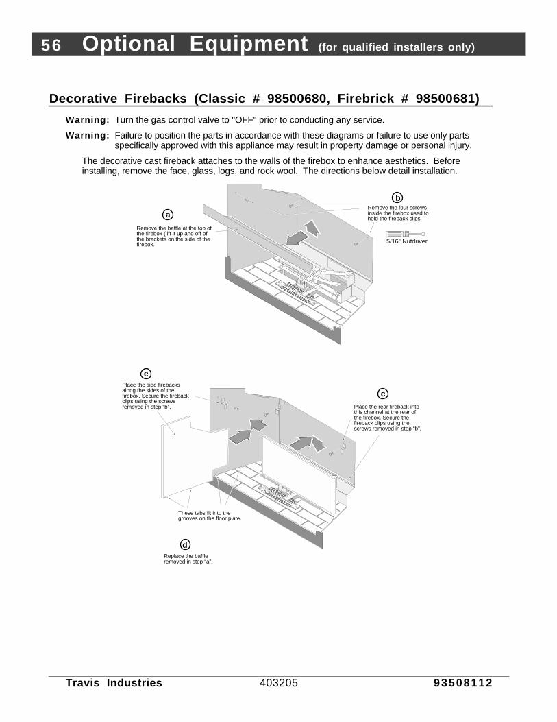
56 Optional Equipment (for qualified installers only)
Travis Industries 403205 93508112
Decorative Firebacks (Classic # 98500680, Firebrick # 98500681)
Warning: Turn the gas control valve to "OFF" prior to conducting any service.
Warning: Failure to position the parts in accordance with these diagrams or failure to use only partsspecifically approved with this appliance may result in property damage or personal injury.
The decorative cast fireback attaches to the walls of the firebox to enhance aesthetics. Beforeinstalling, remove the face, glass, logs, and rock wool. The directions below detail installation.
5/16" Nutdriver
AAAAAAAAAAAAAAAAAAAAAAAAAAAAAAAAAAAAAAAAAAAAAAAAAAAAAAAAAAAAAAAAAAAAAAAAAAAAAAAAAAAAAAAAAAA
AAAAAAAAAAAAAAAAAAAAAAAAAAAAAAA
AAAAAAAAAAAAAAAAAAAAAAAAAAAAAAAA
AAAAAAAAAAAAAAAAAAAAAAAAAAAAAAAAAAA
Remove the four screws inside the firebox used to hold the fireback clips.a
b
Remove the baffle at the top of the firebox (lift it up and off of the brackets on the side of the firebox.
Place the rear fireback into this channel at the rear of the firebox. Secure the fireback clips using the screws removed in step “b”.
AAAAAAAAAAAAAAAAAAAAAAAAAAAAAAAAAAAAAAAAAAAAAAAAAAAAAAAAAAAAAAAAAAAAAAAAAAAAAAAAAAAAAAAAAAAAAAAAAAAAAAAA
AAAAAAAAAAAAAAA
AAAAAAAAAAAAAAAAA
AAAAAAAAAAAAAAAAAAAAAAAAAAAAAAAA
AAAAAAAAAAAAAAAAAAAAAAAAAAAAAAAAAAA
dReplace the baffle removed in step “a”.
c
These tabs fit into the grooves on the floor plate.
ePlace the side firebacks along the sides of the firebox. Secure the fireback clips using the screws removed in step “b”.

Optional Equipment (for qualified installers only) 57
Travis Industries 403205 93508112

58 Index
Travis Industries 403205 93508112
Approved Vent Configurations..........................19Adjusting the Blower Speed..............................39Adjusting the Flame Height ...............................38Air Shutter Adjustment......................................34Altitude Considerations.....................................17Blower Control..................................................39BTU Input.........................................................5BTU Output......................................................5Cap (see vent termination).................................24Chimney Cap (see vent termination)...................24Chimney Installation (see Vent Requirements)....17Clearances.......................................................8Condensation on Glass.....................................38Corner Installation.............................................9Dimensions......................................................5Dura-Vent (part numbers)..................................17Elbows.............................................................19Electrical Connection........................................26Face Dimensions..............................................13Face Installation................................................35Facing Requirements........................................11Finalizing the Installation....................................27Floor Protection (see "Hearth Requirements")....10Framing Dimensions .........................................7Fuel .................................................................25Gas Control Valve (Location)..............................36Gas Inlet Pressure.............................................25Gas Line Connection ........................................25Gas Line Install..................................................25Gas Smell .................................See Inst. on CoverGlass Installation and Removal ...........................27Hearth Requirements........................................10Heating Specifications ......................................5Horizontal Vent Termination Requirements ........24How this Fireplace Works...................................42Vent Lengths...................................................19
Installation Options ...........................................5Items Required for Installation............................6Leaking Gas .............................See Inst. on CoverListing Information ............................................44Location of Controls..........................................36Log Set Installation and Removal .......................28Maintenance ....................................................40Mantel Requirements........................................16Measuring Vent Lengths...................................19Noise (see Normal Operating Sounds) ...............39Normal Operating Sounds.................................39Packing List......................................................6Pilot Flame Inspection.......................................33Piping Installation (see Gas Line Install)...............25Raised Fireplaces .............................................8Remote Control Installation................................57Remote Control Operation ................................57Restrictor Position ............................................19Safety Label.....................................................44Safety Precautions ...........................................2Starting The Pilot ..............................................37Starting the Fireplace for the First Time...............38Thermostat Operation.......................................38Turning the Fireplace On and Off .......................38Vent Length (see “Vent Configuration”).............19Vent Part Numbers ...........................................19Vent Requirements ..........................................17Vertical Vent Termination Requirements ............24Warnings..........................................................2Warranty...........................................................45Water on Glass (see Condensation) ...................38Weight (325 Lbs.) .............................................5What Prevents Gas Buildup...............................42What Turns the Main Burners On and Off............42Wiring Diagram..................................................43Yearly Service Procedure..................................40