ZCP mu13947.pdf
36
Novenco Air Handling Units Climaster ZCP June 2005
Transcript of ZCP mu13947.pdf

Novenco Air Handling Units
Climaster ZCP June 2005
2 ZCP
Product Facts
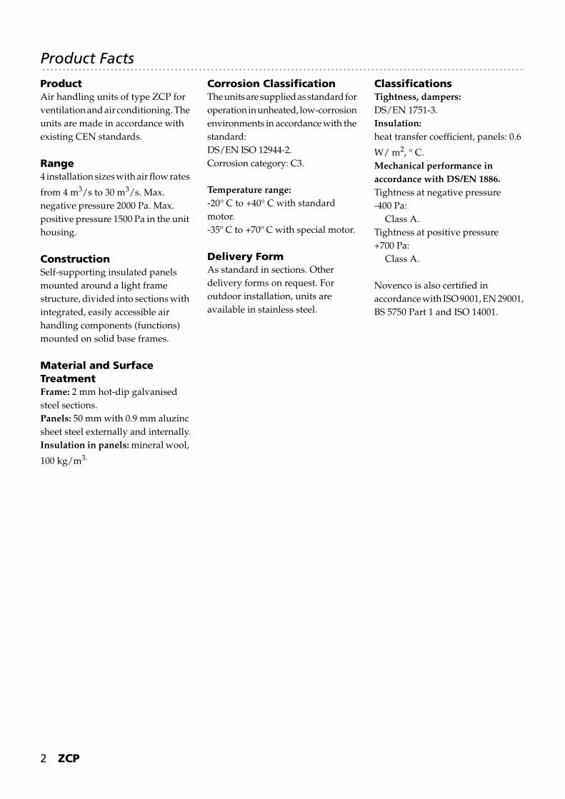
ProductAir handling units of type ZCP for ventilation and air conditioning. The units are made in accordance with existing CEN standards.
Range4 installation sizes with air flow rates
from 4 m3/s to 30 m3/s. Max. negative pressure 2000 Pa. Max. positive pressure 1500 Pa in the unit housing.
ConstructionSelf-supporting insulated panels mounted around a light frame structure, divided into sections with integrated, easily accessible air handling components (functions) mounted on solid base frames.
Material and Surface TreatmentFrame: 2 mm hot-dip galvanised steel sections.Panels: 50 mm with 0.9 mm aluzinc sheet steel externally and internally.Insulation in panels: mineral wool,
100 kg/m3.
Corrosion ClassificationThe units are supplied as standard for operation in unheated, low-corrosion environments in accordance with the standard:DS/EN ISO 12944-2.Corrosion category: C3.
Temperature range:-20° C to +40° C with standard motor.-35º C to +70º C with special motor.
Delivery FormAs standard in sections. Other delivery forms on request. For outdoor installation, units are available in stainless steel.
ClassificationsTightness, dampers:DS/EN 1751-3.Insulation:heat transfer coefficient, panels: 0.6
W/ m2, ° C. Mechanical performance in accordance with DS/EN 1886.Tightness at negative pressure -400 Pa:
Class A.Tightness at positive pressure +700 Pa:
Class A.
Novenco is also certified in accordance with ISO 9001, EN 29001, BS 5750 Part 1 and ISO 14001.
ZCP 3
Novenco Climaster ZCP
Description and Capacity Diagram 4
Cross-sectional Dimensions and Connections 6
Dimensions Tables 7
Range and Construction 8
Functions 9
Dampers 12
Filters 13
Heating Coils for Water 14
Cooling Coils for Water 16
Cooling Coils for Direct Expansion 18
Electric Heating Coils 18
Twin-coil Heat Exchangers 19
Humidifiers 20
Silencers 22
Novax Axial Flow Fans 23
Centrifugal Fans 27
MU 13947 0605
4 ZCP
Description and Capacity Diagram
Louvre damper
Heating and cooling coils
Humidifiers
Centrifugal Fans
Axial Flow Fans
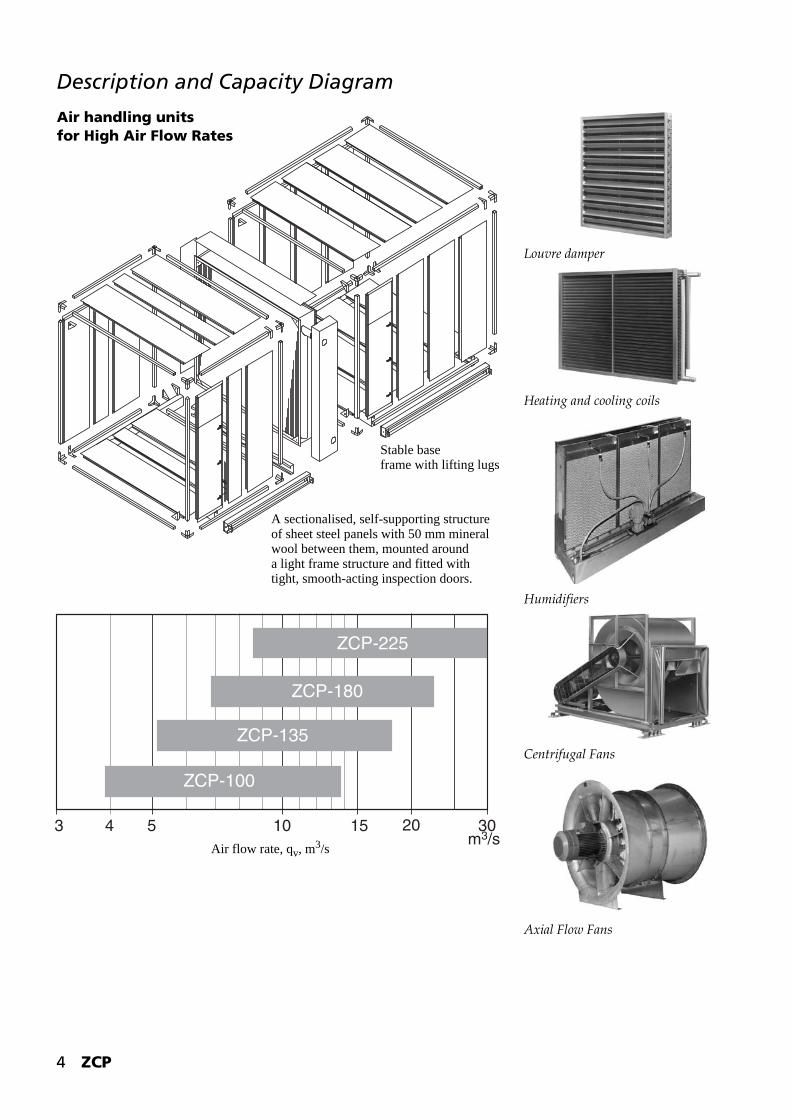
5 10 20 30153 4m3/s
ZCP-180
ZCP-225
ZCP-135
ZCP-100
Stable baseframe with lifting lugs
A sectionalised, self-supporting structureof sheet steel panels with 50 mm mineralwool between them, mounted arounda light frame structure and fitted withtight, smooth-acting inspection doors.
Air flow rate, qv, m3/s
Air handling units for High Air Flow Rates
ZCP 5
The Climaster ZCP is a system of air handling units for individual combination of air handling functions for individual air conditions.The construction of the system is described in further detail on page 8.
UseZCP is used in large ventilation and air conditioning systems, including installations with high requirements for the condition of the air.
RangeZCP units are available in 4 sizes with air flow rates up to 30 m3/s and pressures up to 2000 Pa.
FunctionsThe functions (components) included comprise:- Dampers for shut-off, mixing and
recirculation.- Filters with different degrees of
separation.- Heating and cooling coils for
water for heating and cooling the air and for twin-coil heat recovery systems.
- Cooling coils for direct expansion.- Electric heating coils.- Humidifiers.- Double inlet centrifugal fans or
axial flow fans with fixed blades.- Silencers.- Inspection rooms with or without
doors.
ConstructionThe unit housings are made of self-supporting insulated panels mounted around a light frame structure, divided into sections with integrated, easily accessible air handling components. The sections are mounted on solid base frames.Construction details for the individual components are specified
under the components on pages 12-34.
Material and Surface TreatmentThe unit housing consists of hot-dip galvanised steel sections and aluzinc sheet steel.The panels are a sandwich construction of 2 layers of 0.9 mm aluzinc sheet steel with an intermediate layer of 50 mm mineral wool, 100 kg/m3.The surfaces are unpainted.The material and finishing of the individual components are described under the components.
DrainsWet sections (cooling coils and humidifiers) are fitted with waterproof drip pans with drains out through the access side.The drain must be provided with a water trap and must be installed with a gentle incline to an open floor drain. Novenco can supply a special plastic water trap.
Delivery and InstallationThe units are delivered as standard in sections. Other methods of delivery can be arranged. The sections are easy to assemble. Detailed installation instructions are supplied.
Accessories and Special Versions- Inlet vane control for centrifugal
fans.- Inspection windows.- Internal light.- Safety switch.- Non-slip bottom plating.- Special water trap for drain.- Baffle plates for fan outlet *).- Flexible connections, etc.
*) When using baffle plates after a fan outlet, the total distance from the fan’s pressure boss to the subsequent component (for example, sound baffles) must be:
ZCP units are available in stainless steel for outdoor installation.The units are also available in a special reinforced two-way version for both supply and extraction. Systems with two-way units must only be implemented in cooperation with Novenco.
Centrifugal fan size Distance
-710 580-800 650-900 730
-1000 820
Axial flow fan size
Distance
-900 810-1000 900-1120 1008-1250 1125

6 ZCP
Cross-sectional Dimensions and Connections
Position DesignationsMain position of the unit, seen from the access side:Pos. R: Air flow direction to the right.Pos. L: Air flow direction to the left.
Connection Positions:(See the dimensioned drawings) Inlet, mixing damper: Pos. 1, 2 and 4.Outlet, centrifugal fan: Pos. A, B, C, D, E and F.
Mixing Damper, SB
Pos. 2
Pos. 1
Pos. 4
Inlet damper SF* and outlet with end panel.* Only for heating and cooling coils, both intermediate and integrated
Outlet, centrifugal fans,pos. B & C.
Outlet, axial flow fans.
Inlet damper SF*at top: pos. 1(at bottom: pos. 4).
Inlet damper SB* Mixing damper SA* Outlet, centrifugal fanat top: pos. 1 - 2(at bottom: pos. 4 - 2).
at top: pos. 1(at bottom: pos. 4).
at top: pos. A and E(at bottom: pos. D and F).
* Dampers on ZCP-225 are in two parts: 2 C (C1) x N
Position A Position E

ZCP 7
Dimensions Tables
Outlet Positions, Centrifugal Fan CL
Pos. F Pos. B
Pos. A
Pos. D
Pos. E
Pos. C
Dimensions in mm
Outlet – Centrifugal Fans CL
Outlet – Axial Flow Fans AC
ZCP-100 ZCP-135 ZCP-180 ZCP-225
Main dimensions
H 1930 1930 2540 2540
B1 1930 2540 2540 3150
B2 2136 2746 2746 3356
Inlet andconnections
A 265 265 270 270
B 1400 2000 2000 2750
C 1400 1400 2000 2000
C1 1000 1000 1200 1200
P 162.5 162.5 215 215
R 110 110 162.5 162.5
M 220 220 325 325
N - - - 1300
S 265 270 270 200
ZCP-100 ZCP-135 ZCP-180 ZCP-225
CL -710 -800 -710 -800 -900 -800 -900 -1000 -900 -1000
E 510 455 815 760 700 760 700 630 1005 935
F 910 1020 910 1020 1140 1020 1140 1280 1140 1280
G 910 1020 910 1020 1140 1020 1140 1280 1140 1280
J1 586 684 586 684 624 684 624 706 624 706
J2 278 250 278 250 190 250 190 249 190 249
L 586 531 586 531 624 531 624 706 624 706
L1 744 689 744 689 781 689 781 864 781 864
ZCP-100 ZCP-135 ZCP-180 ZCP-225
ACG -900 -1000 -1000 -1120 -1120 -1250 -1250
dia. D 1000 1120 1120 1250 1250 1400 1400
E1 965 965 1270 1270 1270 1270 1575
K 1033 1093 1093 1100 1153 1203 1203
8 ZCP
Range and Construction
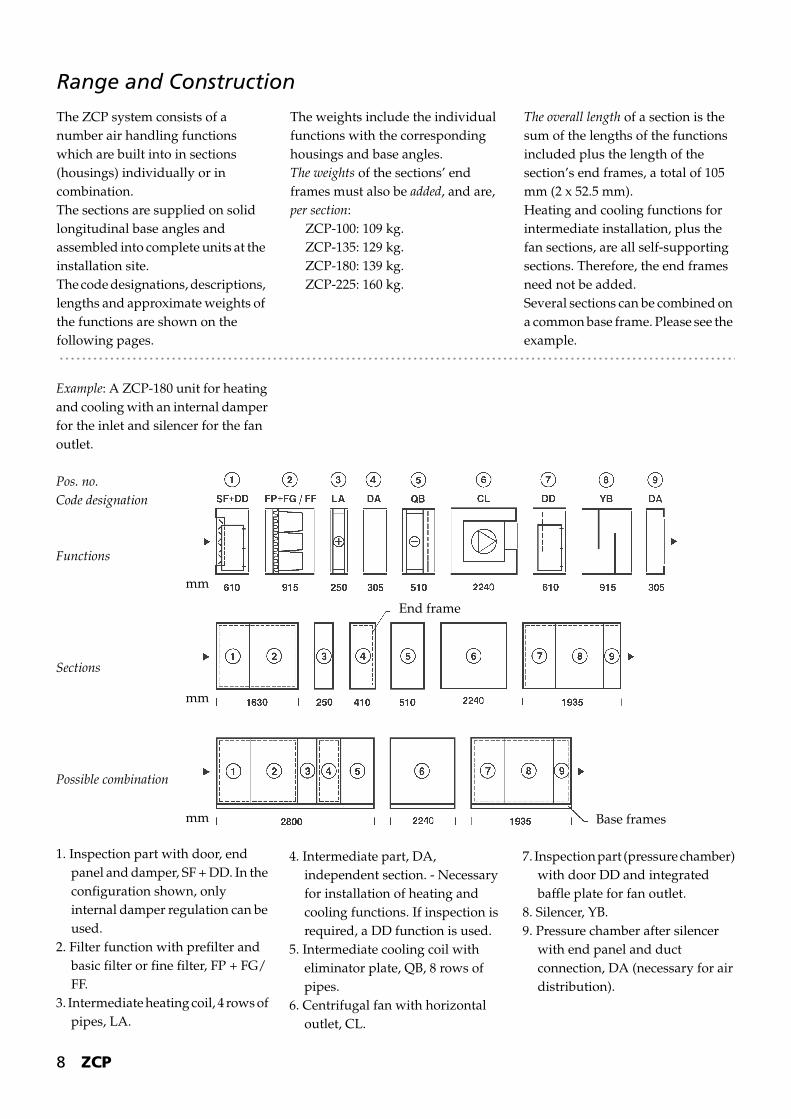
The ZCP system consists of a number air handling functions which are built into in sections (housings) individually or in combination.The sections are supplied on solid longitudinal base angles and assembled into complete units at the installation site.The code designations, descriptions, lengths and approximate weights of the functions are shown on the following pages.
The weights include the individual functions with the corresponding housings and base angles.The weights of the sections’ end frames must also be added, and are, per section:
ZCP-100: 109 kg.ZCP-135: 129 kg.ZCP-180: 139 kg.ZCP-225: 160 kg.
The overall length of a section is the sum of the lengths of the functions included plus the length of the section’s end frames, a total of 105 mm (2 x 52.5 mm).Heating and cooling functions for intermediate installation, plus the fan sections, are all self-supporting sections. Therefore, the end frames need not be added.Several sections can be combined on a common base frame. Please see the example.
Example: A ZCP-180 unit for heating and cooling with an internal damper for the inlet and silencer for the fan outlet.
Pos. no.Code designation
Functions
Sections
Possible combination
1. Inspection part with door, end panel and damper, SF + DD. In the configuration shown, only internal damper regulation can be used.
2. Filter function with prefilter and basic filter or fine filter, FP + FG/FF.
3. Intermediate heating coil, 4 rows of pipes, LA.
4. Intermediate part, DA, independent section. - Necessary for installation of heating and cooling functions. If inspection is required, a DD function is used.
5. Intermediate cooling coil with eliminator plate, QB, 8 rows of pipes.
6. Centrifugal fan with horizontal outlet, CL.
7. Inspection part (pressure chamber) with door DD and integrated baffle plate for fan outlet.
8. Silencer, YB.9. Pressure chamber after silencer
with end panel and duct connection, DA (necessary for air distribution).
Base frames
End frame
mm
mm
mm

ZCP 9
Functions
* NB: When using these filter functions, there must be a function with inspection access immediately before it for changing the filter.
** NB: The filter is changed from the clean side. This is not an optimal solution.
Code Symbol FunctionZCP
-100 -135 -180 -225
SF Shut-off damper.Mounted externally or internally on the end panel.Internal damper is mounted in a DA function, length 305 mm.
LengthWeight
30589
305112
305141
305181
mmkg
SF Shut-off damper.Mounted on top of the housing.Alternative mountinginternally in the bottom of the housing.
LengthWeight
1525311
1525348
2135544
2135613
mmkg
SA Mixing and recirculation damper.Incl. 2 inspection doors. Length
Weight2440588
2440669
3050918
30501055
mmkg
SB Mixing damper.Incl. 1 inspection door. Length
Weight1220338
1220390
1525529
1525618
mmkg
FP* Flat filter,basic filter. Length
Weight30598
305120
305145
305172
mmkg
(FP)+FG*
Pocket filter,base filter.Can be supplemented with an FP flat filter as a prefilter.
LengthWeight
610163
610193
610227
610269
mmkg
FP+FG/FF**
Pocket filter.Base or fine filter supplemented with an FP flat filter as a prefilter. With or without inspection door.
LengthWeight
915224
915268
915317
915368
mmkg
Assembly into Sections (example on page 8):
Function:Lengths, mm
1 + 2610 + 915 + 105
+ 3250
+ 4305 + 105
+ 5510
= total2800
Function:Lengths, mm
62240
(No addition for frame section in 3 and 5as the functions are independent sections.)
= total2240
Function:Lengths, mm
7 + 8 + 9610 + 915 + 305 + 105
= total1935
Total length of unit, mmTotal weight of unit, kg
69754482
10 ZCP
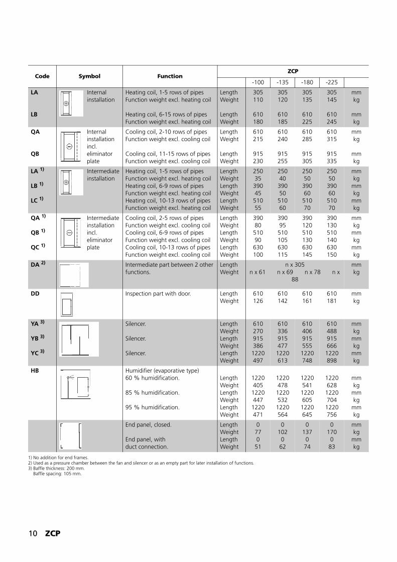
1) No addition for end frames.2) Used as a pressure chamber between the fan and silencer or as an empty part for later installation of functions.3) Baffle thickness: 200 mm. Baffle spacing: 105 mm.
Code Symbol FunctionZCP
-100 -135 -180 -225
LA
LB
Internal installation
Heating coil, 1-5 rows of pipesFunction weight excl. heating coil
Heating coil, 6-15 rows of pipesFunction weight excl. heating coil
LengthWeight
LengthWeight
305110
610180
305120
610185
305135
610225
305145
610245
mmkg
mmkg
QA
QB
Internal installation incl. eliminator plate
Cooling coil, 2-10 rows of pipesFunction weight excl. cooling coil
Cooling coil, 11-15 rows of pipesFunction weight excl. cooling coil
LengthWeight
LengthWeight
610215
915230
610240
915255
610285
915305
610315
915335
mmkg
mmkg
LA 1)
LB 1)
LC 1)
Intermediate installation
Heating coil, 1-5 rows of pipesFunction weight excl. heating coilHeating coil, 6-9 rows of pipesFunction weight excl. heating coilHeating coil, 10-13 rows of pipesFunction weight excl. heating coil
LengthWeightLengthWeightLengthWeight
250353904551055
25040
39050
51060
25050
39060
51070
25050
39060
51070
mmkg
mmkg
mmkg
QA 1)
QB 1)
QC 1)
Intermediate installation incl. eliminator plate
Cooling coil, 2-5 rows of pipesFunction weight excl. cooling coilCooling coil, 6-9 rows of pipesFunction weight excl. cooling coilCooling coil, 10-13 rows of pipesFunction weight excl. cooling coil
LengthWeightLengthWeightLengthWeight
3908051090630100
39095
510105630115
390120510130630145
390130510140630150
mmkg
mmkg
mmkg
DA 2) Intermediate part between 2 other functions.
LengthWeight
n x 305n x 61 n x 69 n x 78 n x
88
mmkg
DD Inspection part with door. LengthWeight
610126
610142
610161
610181
mmkg
YA 3)
YB 3)
YC 3)
Silencer.
Silencer.
Silencer.
LengthWeightLengthWeightLengthWeight
610270915386
1220497
610336915477
1220613
6104069155551220748
6104889156661220898
mmkg
mmkg
mmkg
HB Humidifier (evaporative type)60 % humidification.
85 % humidification.
95 % humidification.
LengthWeightLengthWeightLengthWeight
1220405
1220447
1220471
1220478
1220532
1220564
122054112206051220645
122062812207041220756
mmkg
mmkg
mmkg
End panel, closed.
End panel, withduct connection.
LengthWeightLengthWeight
0770
51
0102062
0137074
0170
083
mmkg
mmkg

ZCP 11
Standard EquipmentAll fans are mounted on anti-vibration mountings (centrifugal fans – spring anti-vibration mountings; axial flow fans - rubberanti-vibration mountings) and provided with an internal flexible connection for the outlet.All fan sections are also provided with inspection doors.
Sensor and drain outlet on heating and cooling coils.
Accessories- Inlet vane control for centrifugal
fans.- Inspection windows.- Internal light.- Safety switch.- Non-slip bottom plating.- Water trap for drain.- Baffle plates for fan outlet- Flexible connections, etc.- Air flow rate measuring nozzle,
only for axial flow fans.- Manometers for filter relay.
1) Excl. weight of motor.
Code Symbol FunctionZCP
-100 -135 -180 -225
CLPos. B or C.
Centrifugal fan with horizontal outlet(Pos. B or C).
Fan, CL-710(ZCP-100 and -135)
Fan, CL-800(ZCP-100, -135 and -180)
Fan, CL-900(ZCP-135, -180 and -225)
Fan, CL-1000(ZCP-180 and -225)
LengthWeight 1)
LengthWeight 1)
LengthWeight 1)
LengthWeight 1)
1935910
22401055
19351007
22401160
25451344
22401265
25451455
25451560
25451598
25451703
mmkg
mmkg
mmkg
mmkg
CLPos. A, D, E or F.
Centrifugal fan with vertical outlet(Pos. A, D, E or F).
Fan, CL-710(ZCP-100 and -135)
Fan, CL-800(ZCP-100, -135 and -180)
Fan, CL-900(ZCP-135, -180 and -225)
Fan, CL-1000(ZCP-180 and -225)
LengthWeight 1)
LengthWeight 1)
LengthWeight 1)
LengthWeight 1)
2240975
22401055
22401080
22401160
25451455
22401265
25451455
28501642
25451598
28501793
mmkg
mmkg
mmkg
mmkg
AC
Novax axial flow fan with adjusted blades.
Fan ACG-900(ZCP-100)
Fan ACG-1000(ZCP-100 and -135)
Fan ACG-1120(ZCP-135 and -180)
Fan ACG-1250(ZCP-180 and -225)
LengthWeight 1)
LengthWeight 1)
LengthWeight 1)
LengthWeight 1)
1935843
1935968
19351073
19351247
19351372
19351426
19351587
mmkg
mmkg
mmkg
mmkg
12 ZCP
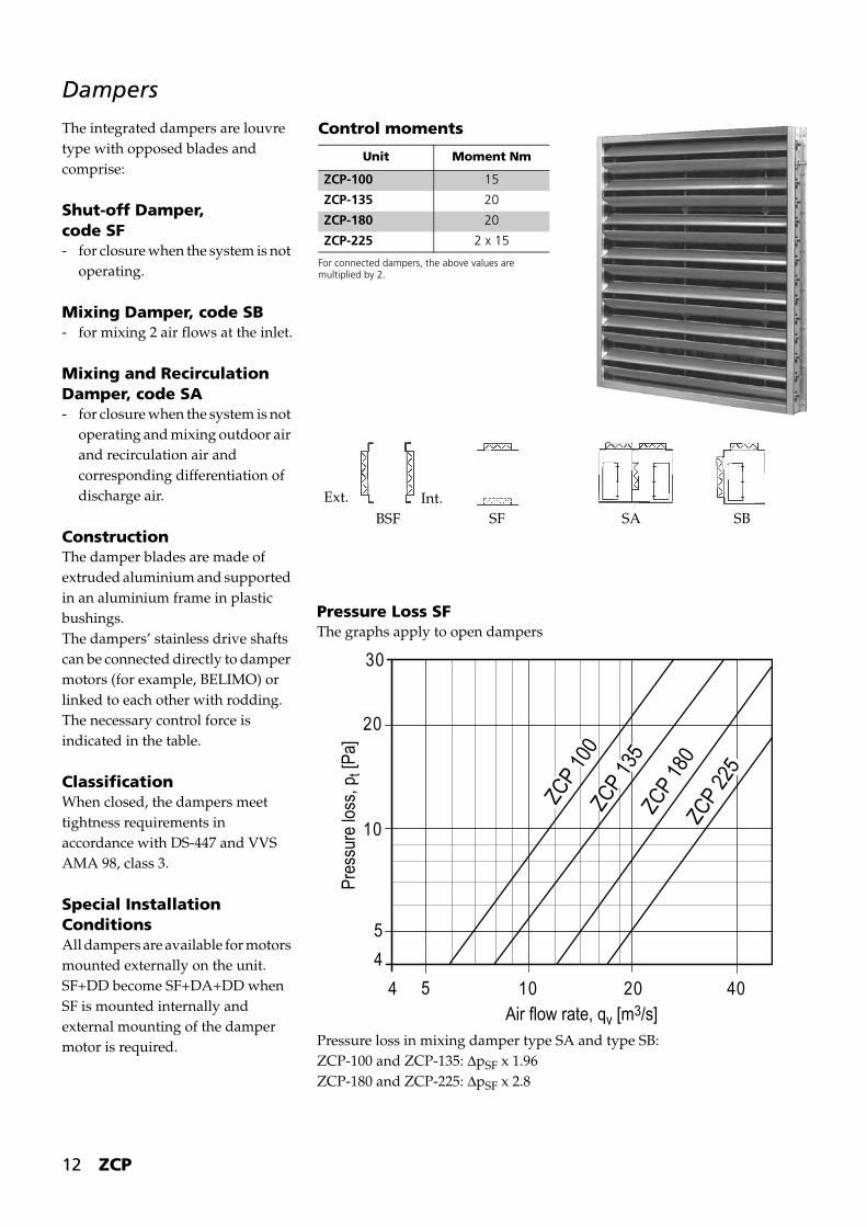
Dampers
The integrated dampers are louvre type with opposed blades and comprise:
Shut-off Damper,code SF- for closure when the system is not
operating.
Mixing Damper, code SB- for mixing 2 air flows at the inlet.
Mixing and Recirculation Damper, code SA- for closure when the system is not
operating and mixing outdoor air and recirculation air and corresponding differentiation of discharge air.
ConstructionThe damper blades are made of extruded aluminium and supported in an aluminium frame in plastic bushings.The dampers’ stainless drive shafts can be connected directly to damper motors (for example, BELIMO) or linked to each other with rodding.The necessary control force is indicated in the table.
ClassificationWhen closed, the dampers meet tightness requirements in accordance with DS-447 and VVS AMA 98, class 3.
Special Installation ConditionsAll dampers are available for motors mounted externally on the unit.SF+DD become SF+DA+DD when SF is mounted internally and external mounting of the damper motor is required.
Control moments
For connected dampers, the above values are multiplied by 2.
Unit Moment Nm
ZCP-100 15
ZCP-135 20
ZCP-180 20
ZCP-225 2 x 15
Ext. Int.BSF SBSASF
Pressure Loss SFThe graphs apply to open dampers
Pressure loss in mixing damper type SA and type SB:ZCP-100 and ZCP-135: ΔpSF x 1.96ZCP-180 and ZCP-225: ΔpSF x 2.8
30
20
10
5
4
5 10 20 404
ZCP
100
ZCP
135
ZCP
180
ZCP
225
Air flow rate, qv [m3/s]
Pres
sure
loss
, pt [
Pa]

ZCP 13
Filters
The filter units for the Climaster units are supplied mounted in special frames and are available in different types, depending on the specific cleanness and separation requirements for the ventilation air.
PrefiltersFor cleanness requirements that specify a filter of class F8, we
recommend mounting a basic filter as a prefilter.The filters meet the requirements for EN 779 and ASHRAE 52-76.The EN 779 classifications for the individual filters are stated in front of the filter types.
Further filter data can be obtained from one of Novenco’s sales representatives.
Flat filter FS (synthetic)
Flat filter FM (metal)
Pocket filter FG (basic filter)
Pocket filter FF (fine filter)
Compact filter FF (fine filter)
Filter typeDescrip-tion of filter
Filter class
Designation
MaterialDiscolouration
Length of filter units
Basic filterswith degree of separation80 - 85%
Flat filters
Pocket filters
EU2
EU3
EU3
FM,PERM ALUFS,AM-300FG
Cleanable aluminium filter
Disposable filter of synthetic material
48 mm
50 mm
305 mm
Fine filterswith degree of separationover 95 %
Pocket filters
EU5 FF Disposable filter of glass fibre material
55 % 305 mm
EU6 FF 65 % 635 mm
EU7 FF 85 % 635 mm
EU8/9 FF 95 % 635 mm
Compact-filters
EU6 VV6-6 Disposable filter of glass fibre medium with a polystyrene frame
65 % 292 mm
EU7 VV6-9 85 % 292 mm
EU8 VV6-10 95 % 292 mm
Number of filter units per air channel
ZCP-100Total of 9. Filter dimensions: 592 mm x 592 mm
ZCP-135Total of 12. Filter dimensions: 592 mm x 592 mm
ZCP-180Total of 16. Filter dimensions: 592 mm x 592 mm
ZCP-225Total of 20. Filter dimensions: 592 mm x 592 mm

14 ZCP
Heating Coils for Water
The heating coils consist of copper pipes with aluminium fins housed in a sheet steel frame.The heating coils are used as preheating and reheating coils.The heating coils are available with different numbers of pipes and circuits, depending on the actual heating requirements.
The heating coils are available asA: built-in coils, mounted in rails in the unit, and B: intermediate coils, where the heating coil’s frame is insulated and mounted together with the rest of the unit as a separate section.
To achieve the greatest possible face area, the heating coils’ header is always mounted outside the unit and covered with an insulated, airtight hood.The water is supplied and discharged through steel headers that pass through the hood on the access side of the unit and have threaded connections at their ends.
ConnectionIt is important that the water flow through the heating coil always equals the calculated flow.
This is best ensured by modulating regulation of the water temperature by means of a separate circuit in connection with a shunt arrangement close to the heating coil, as shown in the accompanying diagram.
Precise temperature regulation without fluctuations in the air temperature is then achieved. The system should also have automatic controls and thermometers, etc., as shown in the diagram.
VRVR t Vt VM t VRVR
t t Vt VVP2 P1
VKVK
LALBLC
Heating coilVM = Motorised valveV = Shut-off valveVR = Regulation and shut-off valveVK = Automatic nonreturn valveP1 = Circulation pump for heating system
(primary circuit)P2 = Circulation pump for heating coil
(secondary circuit)t = Thermometer
Type designation (example):HW-TR-2-2370-2340-2R-39-V1-Cu/Al
Cu pipe/Al finsPosition designationNumber of circuitsNumber of rows of pipesFin height (mm)Fin width (mm)Fin spacing (mm)Pipe division 60 x 30 mmHeating coil for water
*) Other material combinations are available on request.
Technical specifications HW
Pipes * 5/8” Cu 0.45 mmPipe division TR 60 x 30Fins * Al 0.13 mmFin spacing 1.6 – 2.0 – 2.5 and 3.0 mmFrame * Hot-dip galvanised sheet steelPipe socket 11/4” to 4”Vent connection YesBoss for stem bulb sensor YesDrain screw YesMax. working pressure 10 barTest pressure under water at 20°C 30 barMax. working temp. 100 °CPosition V1 right - V2 left
ZCP 15
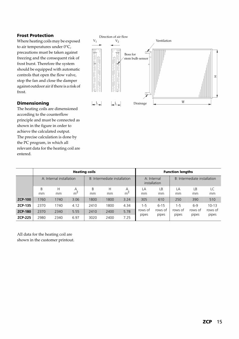
Frost ProtectionWhere heating coils may be exposed to air temperatures under 0°C, precautions must be taken against freezing and the consequent risk of frost burst. Therefore the system should be equipped with automatic controls that open the flow valve, stop the fan and close the damper against outdoor air if there is a risk of frost.
DimensioningThe heating coils are dimensioned according to the counterflow principle and must be connected as shown in the figure in order to achieve the calculated output.The precise calculation is done by the PC program, in which all relevant data for the heating coil are entered.
All data for the heating coil are shown in the customer printout.
L L W
H
Drainage
Ventilation
Boss forstem bulb sensor
V2V1
Direction of air flow
Heating coils Function lengths
A: Internal installation B: Intermediate installation A: Internal installation
B: Intermediate installation
Bmm
Hmm
Am2
Bmm
Hmm
Am2
LAmm
LBmm
LAmm
LBmm
LCmm
ZCP-100 1760 1740 3.06 1800 1800 3.24 305 610 250 390 510
ZCP-135 2370 1740 4.12 2410 1800 4.34 1-5 rows of pipes
6-15 rows of pipes
1-5 rows of pipes
6-9 rows of pipes
10-13 rows of pipes
ZCP-180 2370 2340 5.55 2410 2400 5.78
ZCP-225 2980 2340 6.97 3020 2400 7.25
16 ZCP
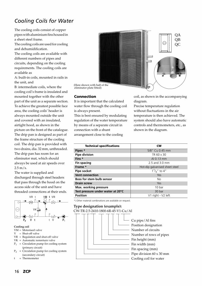
Cooling Coils for Water
The cooling coils consist of copper pipes with aluminium fins housed in a sheet steel frame.The cooling coils are used for cooling and dehumidification.The cooling coils are available with different numbers of pipes and circuits, depending on the cooling requirements. The cooling coils are available as A: built-in coils, mounted in rails in the unit, andB: intermediate coils, where the cooling coil’s frame is insulated and mounted together with the other part of the unit as a separate section.To achieve the greatest possible face area, the cooling coils’ header is always mounted outside the unit and covered with an insulated, airtight hood, as shown in the picture on the front of the catalogue.The drip pan is designed as part of the frame structure of the cooling coil. The drip pan is provided with two drains, dia. 32 mm, unthreaded. The drip pan has room for an eliminator mat, which should always be used at air speeds over 2.5 m/s.The water is supplied and discharged through steel headers that pass through the hood on the access side of the unit and have threaded connections at their ends.
ConnectionIt is important that the calculated water flow through the cooling coil is always present.This is best ensured by modulating regulation of the water temperature by means of a separate circuit in connection with a shunt arrangement close to the cooling
coil, as shown in the accompanying diagram.Precise temperature regulation without fluctuations in the air temperature is then achieved. The system should also have automatic controls and thermometers, etc., as shown in the diagram.
VRVR t Vt VM t VRVR
t t Vt VVP2 P12
VKVK
(Here shown with half of theeliminator plate fitted)
QAQBQC
*) Other material combinations are available on request.
Technical specifications CW
Pipes * 5/8” Cu 0.45 mmPipe division TR 60 x 30Fins * Al 0.13 mmFin spacing 2.5 and 3.0 mmFrame * Hot-dip galvanised sheet steelPipe socket 11/4” to 4”Vent connection YesBoss for stem bulb sensor NoDrain screw YesMax. working pressure 10 barTest pressure under water at 20°C 30 barPosition V1 right - V2 left
Type designation (example):CW-TR-2.5-2410-1800-6R-45-V1-Cu/Al
Cu pipe/Al finsPosition designationNumber of circuitsNumber of rows of pipesFin height (mm)Fin width (mm)Fin spacing (mm)Pipe division 60 x 30 mmCooling coil for water
Cooling coilVM = Motorised valveV = Shut-off valveVR = Regulation and shut-off valveVK = Automatic nonreturn valveP1 = Circulation pump for cooling system
(primary circuit)P2 = Circulation pump for cooling system
(secondary circuit)t = Thermometer

ZCP 17
DimensioningThe cooling coils are dimensioned according to the counterflow principle and must be connected as shown in the figure in order to achieve the design output.The precise calculation is done by the PC program, in which all relevant data for the cooling coil are entered. All data for the cooling coil are shown in the customer printout.
Special Water TrapIt is beneficial to use Novenco’s special water trap for drains from wet sections.Please note: There are two drains from the drip pan on cooling coils.
1. Adjusting screw with foot2. Base frame3. Drip pan4. Drain connection, 32 mm ext.
diameter without thread5. Angle6. Pipe, dia. 32 mm7. Water trap8. Ball9. Drain, 32 mm ext. diameter
without thread
30-70 mm 1
3
2
6 5 49 8 7
H88
Cooling coils Function lengths *
A: Internal installation B: Intermediate installation A: Internal installation
B: Intermediate installation
Bmm
Hmm
Am2
Bmm
Hmm
Am2
QAmm
QBmm
QAmm
QBmm
QCmm
ZCP-100 1760 1740 3.06 1800 1800 3.24 610 915 390 510 630
ZCP-135 2370 1740 4.12 2410 1800 4.34 2-10 rows of pipes
11-15 rows of pipes
1-5 rows of pipes
6-9 rows of pipes
10-13 rows of pipes
ZCP-180 2370 2340 5.55 2410 2400 5.78
ZCP-225 2980 2340 6.97 3020 2400 7.25
L L
H
W
Direction of air flow
Pos. R Pos. LVentilation
Drainage
Room for
Drain from drip pan 2 drains with unthreaded pipes, dia.
eliminatormat
18 ZCP
Cooling Coils for Direct Expansion
Cooling coils (DX) for systems for direct expansion of the cooling medium are available with the same number of rows of pipes and in the same materials as cooling coils for water. However, inlet pipes and outlet pipes are made of copper.DX cooling coils have the same front area and function length and the
same drip pan with eliminator mat and are installed in the same function as water cooling coils.
Inlet and outlet pipes pass through the panel. DX cooling coils are supplied without expansion valves. The expansion valve should be mounted immediately outside the
cooling function. Information on the calculation of DX cooling coils is available from Novenco.The type designation is the same as for water cooling coils, but with DX instead of CW.
Electric Heating CoilsElectric heating coils for Climaster ZCP are made of stainless steel tubular heating elements integrated in a sheet steel frame with a junction box with the necessary cable terminals.The heating coils are available with various numbers of rows of pipes, depending on the heating requirements.The heating coils are grouped in terms of power in accordance with the actual need.In the standard version, the heating coils are designed for dry rooms that are not at risk of explosion but are available for other operating conditions.The function length is 305 mm and the maximum powers are:
For further details on the design and connection, ask Novenco’s sales departments.
Safety ThermostatsThe heating coils have a maximum thermostat with automatic reclosing (adjustable from 30 to 110°C) and an overheating thermostat (110°C, not adjustable) with manual reclosing after being triggered.
Electrical ConnectionThe heating coils are normally supplied for 3 x 400 V, but are available for other voltages.
Automatic Controls and Safety FunctionsThe automatic control system must be implemented in such a way that the heating coil can only be supplied with voltage when the fan is in operation.If the maximum thermostat is triggered, only the voltage to the tubular heating elements must be cut. Automatic reclosing takes place after cooling by approximately 15°C.If the overheating thermostat is triggered, the fan must stop and other automatic control functions go to the idle position. Before the system is restarted, the thermostat’s reclosing contact is activated.To avoid unnecessary triggering of the overheating thermostat in connection with scheduled system shutdowns, the system should be equipped with an automatic control for cooling, prolonged fan operation.
ZCP-100 690 kW
ZCP-135 925 kW
ZCP-180 1250 kW
ZCP-225 1570 kW

ZCP 19
Twin-coil Heat Exchangers
Twin-coil batteries are a heat recovery system in which the discharge air passes a cooling coil connected by a pipe system to a heating coil in the outdoor air.This system is used where it is inappropriate to combine the supply and extraction function in one unit.The heat transfer medium (water with the addition of glycol) circulates through the pipe system and the discharge air transfers heat to the outdoor air.
A cooling coil is used on the extraction side so that any condensate will be collected in the drip pan, which has a drain.In their external construction and size, both the heating coils and cooling coils are identical to the heating and cooling coils described on pages 14 and 16.
Pipe SystemThe pipe system that connects the two batteries is installed and furnished with a pump and control, safety and monitoring equipment as shown in the simplified diagram.The pipes must be insulated in accordance with the temperature conditions in and around the system.
ControlThe TC control unit controls the motorised valve according to a signal from a sensor in the outdoor air duct (see the diagram at the top).If there is risk of freezing in the extraction cooling coil, the pipe sensor will override the control, forcing the motorised valve to the position in which the heating coil is bypassed.
DimensioningDimensioning is carried out by Novenco sales offices.
T C M
S FFFQVC L
C LSF FF LV DA LA
Extraction
Air supply
Heat
Outdoor air (QF)
Discharge (QA)
Temperature efficiency ηtt2 t1–
t3 t1–--------------=
20 ZCP
Humidifiers
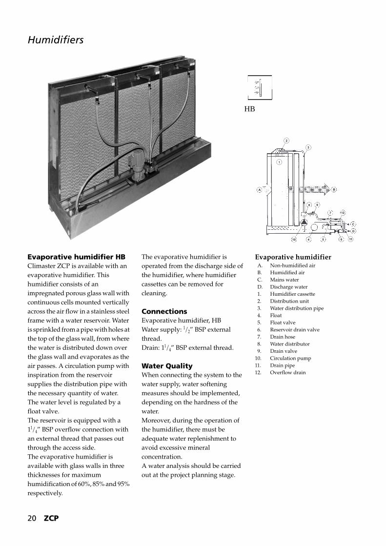
Evaporative humidifier HBClimaster ZCP is available with an evaporative humidifier. This humidifier consists of an impregnated porous glass wall with continuous cells mounted vertically across the air flow in a stainless steel frame with a water reservoir. Water is sprinkled from a pipe with holes at the top of the glass wall, from where the water is distributed down over the glass wall and evaporates as the air passes. A circulation pump with inspiration from the reservoir supplies the distribution pipe with the necessary quantity of water.The water level is regulated by a float valve.The reservoir is equipped with a 11/4” BSP overflow connection with an external thread that passes out through the access side.The evaporative humidifier is available with glass walls in three thicknesses for maximum humidification of 60%, 85% and 95% respectively.
The evaporative humidifier is operated from the discharge side of the humidifier, where humidifier cassettes can be removed for cleaning.
ConnectionsEvaporative humidifier, HBWater supply: 1/2” BSP external thread.Drain: 11/4” BSP external thread.
Water QualityWhen connecting the system to the water supply, water softening measures should be implemented, depending on the hardness of the water.Moreover, during the operation of the humidifier, there must be adequate water replenishment to avoid excessive mineral concentration.A water analysis should be carried out at the project planning stage.
Evaporative humidifierA. Non-humidified airB. Humidified airC. Mains waterD. Discharge water1. Humidifier cassette2. Distribution unit3. Water distribution pipe4. Float5. Float valve6. Reservoir drain valve7. Drain hose8. Water distributor9. Drain valve
10. Circulation pump11. Drain pipe12. Overflow drain
HB
A B
C
D
127
1165410
8 9
3
2
ZCP 21
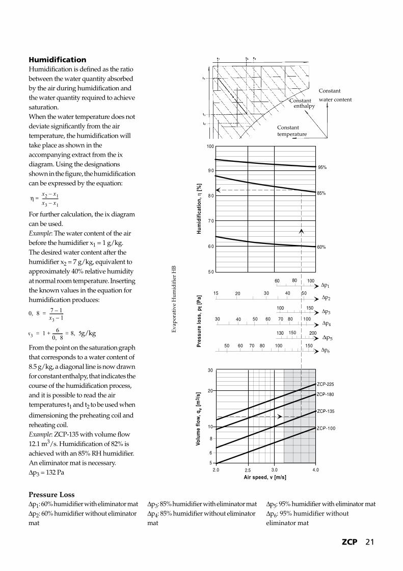
HumidificationHumidification is defined as the ratio between the water quantity absorbed by the air during humidification and the water quantity required to achieve saturation.When the water temperature does not deviate significantly from the air temperature, the humidification will take place as shown in the accompanying extract from the ix diagram. Using the designations shown in the figure, the humidification can be expressed by the equation:
For further calculation, the ix diagram can be used.Example: The water content of the air before the humidifier x1 = 1 g/kg.The desired water content after the humidifier x2 = 7 g/kg, equivalent to approximately 40% relative humidity at normal room temperature. Inserting the known values in the equation for humidification produces:
g/kg
From the point on the saturation graph that corresponds to a water content of 8.5 g/kg, a diagonal line is now drawn for constant enthalpy, that indicates the course of the humidification process, and it is possible to read the air temperatures t1 and t2 to be used when
dimensioning the preheating coil and reheating coil.Example: ZCP-135 with volume flow 12.1 m3/s. Humidification of 82% is achieved with an 85% RH humidifier. An eliminator mat is necessary.Δp3 = 132 Pa
ηx2 x1–
x3 x1–----------------=
0 8, 7 1–x3 1–--------------=
x3 1 60 8,---------- 8 5,=+=
Constant
water contentConstantenthalpy
Constanttemperature
5
6
8
10
20
30
ZCP-180-
ZCP-225
ZCP-135-
ZCP-100-
5 0
9 0
8 0
7 0
6 0
15 20 30 40 50
30 40 50 60 70 80 100
100
50 60 70 80 100 150
150
10080
150100
200130
60%
85%
95%
60
Air speed, v [m/s]
Volu
me
flow,
qv
[m3 /
s]Pr
essu
re lo
ss, p
t [Pa
]Hu
mid
ifica
tion,
η [%
]
2.5 3.0 4.02.0
Eva
pora
tive
Hu
mid
ifie
r H
B
Δp1
Δp2
Δp3
Δp4
Δp5
Δp6
Pressure LossΔp1: 60% humidifier with eliminator matΔp2: 60% humidifier without eliminator mat
Δp3: 85% humidifier with eliminator matΔp4: 85% humidifier without eliminator mat
Δp5: 95% humidifier with eliminator matΔp6: 95% humidifier without eliminator mat
22 ZCP
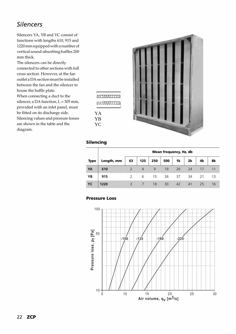
Silencers
Silencers YA, YB and YC consist of functions with lengths 610, 915 and 1220 mm equipped with a number of vertical sound-absorbing baffles 200 mm thick.The silencers can be directly connected to other sections with full cross section. However, at the fan outlet a DA section must be installed between the fan and the silencer to house the baffle plate.When connecting a duct to the silencer, a DA function, L = 305 mm, provided with an inlet panel, must be fitted on its discharge side.Silencing values and pressure losses are shown in the table and the diagram.
YAYBYC
Pressure Loss
1015 20 25 30
50
5 10
100
-100 -135 -180 -225
Air volume, qv [m3/s]
Pres
sure
loss
, pt [
Pa]
Silencing
Mean frequency, Hz, db
Type Length, mm 63 125 250 500 1k 2k 4k 8k
YA 610 2 4 9 19 26 24 17 11
YB 915 2 6 15 26 37 34 21 13
YC 1220 3 7 18 30 42 41 25 16

ZCP 23
Novenco Axial Flow Fans
Axial flow fans with fixed blades for ZCP units are Novax type ACG.The fan is designed as a pipe with a funnel-shaped inlet.
The mount for the motor and impeller is designed to create optimal flow and the motor’s position on the inflow side ensures optimal cooling of the motor.The inlet is provided with a guard net. A downstream guide vane with a core is mounted on the fan’s outlet side, allowing the ACG to achieve a very high efficiency.
The motor is a flanged motor with electrical connection in a junction box.The Novax rotor (the impeller) consists of a pressed, two-part, assembled hub with depressions in which the blades are fixed at predetermined angles. The rotor is provided with a hub boss with a drilled hole for fitting on the motor shaft.The blades of the rotor can be adjusted to any angle between 25° and 60°, depending on the size and RPM.
On the outlet side, the fan is provided with a flexible connection to the outlet panel of the unit.The fan is provided with mounting feet and supported on anti-vibration mountings at the base of the section.The design of the fan in connection with the individually calculated blade angles has the effect that the fan can be supplied with great accuracy for the given operating point with optimal efficiency, typically above 80%.ZCP units include axial flow fans with combinations of impeller and hub diameters as shown in the capacities graph.
For further information on Novax fans, refer to the chapter on Novax.
Investment costs, operating costs and space requirements are often lower for Novax fans than for centrifugal fans with the same performance.
The diagram shows the duty ranges of the individual fan sizes without taking the hub diameter into consideration.The capacities are based on fan installation in accordance with BS 848 1980, installation type B (free inlet, duct connection for outlet).If other installation types are used, other data will be produced.
Specific calculations for Novax fans are carried out in the WinNovax calculation program.
Max. RPM for Novax rotors RPM at 20°C *
* Reduced max. RPM at higher or lower temperatures.
Hub diameter
Rotor diameter
900 1000 1120 1250
380 2651 2324
403 2179 2025 1885 1730
578 2128 1957 1804 1685
Capacities: - ACG Overview
4020105
1500
1000
500
200
100
50
20
2000
7 1 0 8 0 0
9 0 0 1 0 0 0 1 1 2 0 1 2 5 0 1 4 0 0
4kW
5,5
7 ,5
1 1
15
22
30
45kW
1470 RPM
Air flow rate, m3/s
Tota
l pre
ssur
e, P
a
Dimensions
ρ = 1.20 kg/m3
24 ZCP
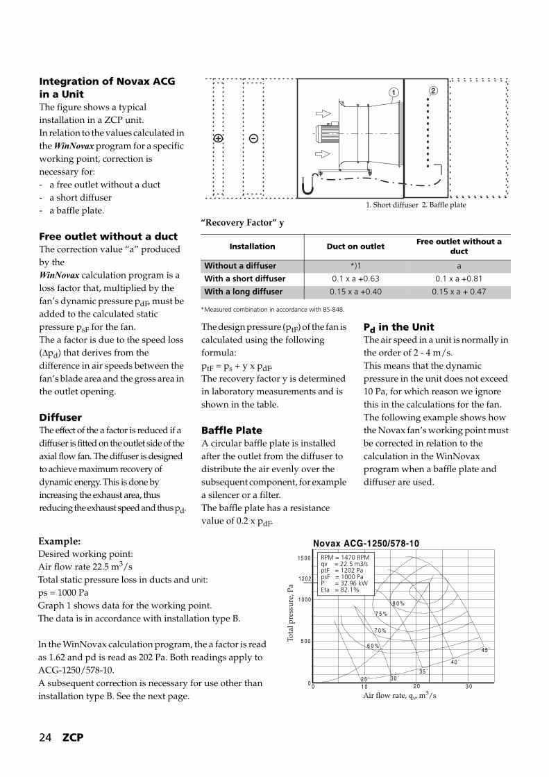
Integration of Novax ACG in a UnitThe figure shows a typical installation in a ZCP unit.In relation to the values calculated in the WinNovax program for a specific working point, correction is necessary for:- a free outlet without a duct- a short diffuser- a baffle plate.
Free outlet without a ductThe correction value “a” produced by the WinNovax calculation program is a loss factor that, multiplied by the fan’s dynamic pressure pdF, must be added to the calculated static pressure psF for the fan.The a factor is due to the speed loss (Δpd) that derives from the difference in air speeds between the fan’s blade area and the gross area in the outlet opening.
DiffuserThe effect of the a factor is reduced if a diffuser is fitted on the outlet side of the axial flow fan. The diffuser is designed to achieve maximum recovery of dynamic energy. This is done by increasing the exhaust area, thus reducing the exhaust speed and thus pd.
The design pressure (ptF) of the fan is calculated using the following formula:ptF = ps + y x pdF.The recovery factor y is determined in laboratory measurements and is shown in the table.
Baffle PlateA circular baffle plate is installed after the outlet from the diffuser to distribute the air evenly over the subsequent component, for example a silencer or a filter.The baffle plate has a resistance value of 0.2 x pdF.
Pd in the UnitThe air speed in a unit is normally in the order of 2 - 4 m/s.This means that the dynamic pressure in the unit does not exceed 10 Pa, for which reason we ignore this in the calculations for the fan.The following example shows how the Novax fan’s working point must be corrected in relation to the calculation in the WinNovax program when a baffle plate and diffuser are used.
“Recovery Factor” y
*Measured combination in accordance with BS-848.
Installation Duct on outletFree outlet without a
duct
Without a diffuser *)1 a
With a short diffuser 0.1 x a +0.63 0.1 x a +0.81
With a long diffuser 0.15 x a +0.40 0.15 x a + 0.47
1. Short diffuser 2. Baffle plate
Example:Desired working point:Air flow rate 22.5 m3/sTotal static pressure loss in ducts and unit:ps = 1000 PaGraph 1 shows data for the working point.The data is in accordance with installation type B.
In the WinNovax calculation program, the a factor is read as 1.62 and pd is read as 202 Pa. Both readings apply to ACG-1250/578-10.A subsequent correction is necessary for use other than installation type B. See the next page.
Novax ACG-1250/578-10
1 0 2 0 3 0
1 2 0 2
1 5 0 0
1 0 0 0
5 0 0
0 0
7 5 %
8 0 %
7 0 %
6 0 %4 5 ˚
4 0 ˚
3 5 ˚3 0 ˚2 5 ˚
Air flow rate, qv, m3/s
Tota
l pre
ssur
e, P
a
RPM = 1470 RPMqv = 22.5 m3/sptF = 1202 PapsF = 1000 PaP = 32.96 kWEta = 82.1%
ZCP 25
Variable RPM Regulation by Means of Frequency InversionThe use of directly coupled fans means that the working range for, for example, 50 Hz motors is as shown in the graphs on page 23, and restrictions in the maximum permissible RPM mean that double-pole motors cannot be used. Therefore, frequency inverters are used together with Novax axial flow fans. This has two effects:
1. Variable regulation of the air flow rate is possible, although it is necessary to be aware that there may be operating situations in which this is not possible, where a specific pre-pressure is required at low air flow rates.
2. It is possible to use the Novax fan
for a higher pressure range than can be achieved with 50 Hz mains operation.
The working range for the four fans mentioned with fixed RPM is shown in the performance graphs on page 23.Where frequency inverters are used, the power of a standard motor can be increased.Page 26 contains examples of the use of frequency inverters.
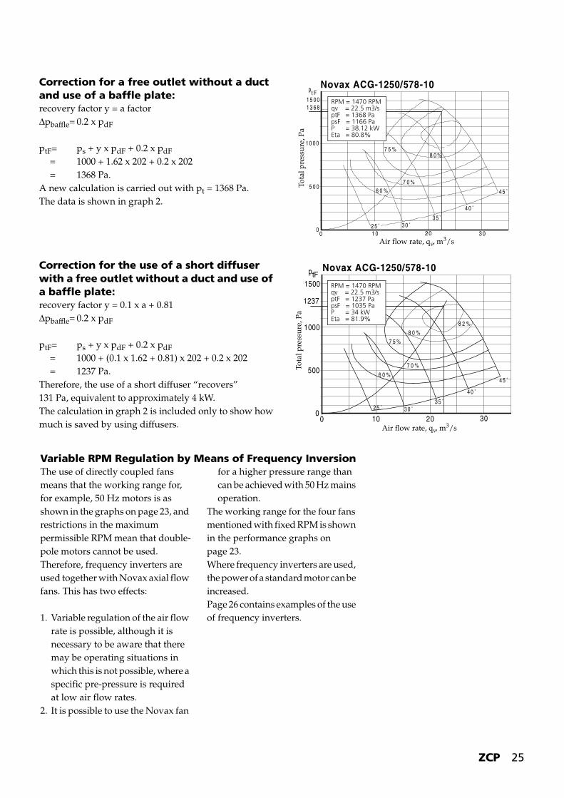
Correction for a free outlet without a duct and use of a baffle plate:recovery factor y = a factorΔpbaffle= 0.2 x pdF
ptF= ps + y x pdF + 0.2 x pdF = 1000 + 1.62 x 202 + 0.2 x 202 = 1368 Pa.A new calculation is carried out with pt = 1368 Pa.The data is shown in graph 2.
Novax ACG-1250/578-10
8 0 %7 5 %
7 0 %6 0 % 4 5 ˚
4 0 ˚
3 5 ˚30 ˚2 5 ˚
1 0 20 3 00
1 5 0 0
1 0 0 0
5 0 0
0
1 3 6 8
pt F
Air flow rate, qv, m3/s
Tota
l pre
ssu
re, P
a
RPM = 1470 RPMqv = 22.5 m3/sptF = 1368 PapsF = 1166 PaP = 38.12 kWEta = 80.8%
Correction for the use of a short diffuser with a free outlet without a duct and use of a baffle plate:recovery factor y = 0.1 x a + 0.81Δpbaffle= 0.2 x pdF
ptF= ps + y x pdF + 0.2 x pdF = 1000 + (0.1 x 1.62 + 0.81) x 202 + 0.2 x 202 = 1237 Pa.Therefore, the use of a short diffuser “recovers”131 Pa, equivalent to approximately 4 kW.The calculation in graph 2 is included only to show how much is saved by using diffusers.
Novax ACG-1250/578-10
10 20 300
1500
1000
500
0
ptF
1237
4 5 ˚
4 0 ˚
3 5 ˚3 0 ˚2 5 ˚
8 2 %
8 0 %7 5 %
6 0 %
7 0 %
Air flow rate, qv, m3/s
Tota
l pre
ssur
e, P
a
RPM = 1470 RPMqv = 22.5 m3/sptF = 1237 PapsF = 1035 PaP = 34 kWEta = 81.9%

26 ZCP
Performance graphs for axial flow fans with 4-pole motors utilised for maximum RPM/power when operated with a frequency inverter.For specific calculations, the WinNovax program is used and a correction is made for use of a short diffuser and any baffle plate, as shown in the example on page 24.The maximum permitted RPM must not be exceeded and the maximum motor size must not be exceeded.
ZCP-100, ZCP-135ACG-1000/380-12, max. motor size -180
ZCP-180, ZCP-225ACG-1250/578-10, max. motor size -225
100 20 300
500
1000
1500
2000
ptF
6 0 ˚
5 5 ˚
5 0 ˚
4 5 ˚
4 0 ˚35˚
30˚
8 3 %
8 0 %7 5 %
7 0 %
6 0 %
2 8 k W
Air flow rate, qv, m3/s
Tota
l pre
ssu
re, P
a
1500
1000
500
00 10 20 30
45˚
40˚
35˚30˚25˚
60%
70%
75%
80% 82%
p tF
47kW
Air flow rate, qv, m3/s
Tota
l pre
ssur
e, P
a
Max. n = 1673 RPM
ZCP-100ACG-900/380-12, max. motor size -180
ZCP-135, ZCP-180ACG-1120/578-10, max. motor size -225
35˚40˚
30˚
45˚
50˚
55˚
60˚
0 10 20 300
1000
2000
ptF
29 kW
65% 70%75%
80%
60%
Air flow rate, qv, m3/s
Tota
l pre
ssur
e, P
a
0 10 20 30
2000
1500
1000
500
ptF
0
65%70%
77%75%
80%
79%
25˚30˚
35˚40˚
45˚
48kW
Air flow rate, qv, m3/s
Tota
l pre
ssur
e, P
a
Max. n = 1804 RPM
Max. n = 2651 RPM Max. n = 2324 RPM

ZCP 27
Centrifugal Fans
Centrifugal fans for ZCP units are double inlet centrifugal fans available in two versions, with forward or backward curved blades.The fan unit - consisting of a fan, motor, V-belt drive and base frame - is mounted on spring anti-vibration mountings. The fan’s outlet flange is connected to the unit with a flexible connection so that vibrations from the fan are not transferred to the unit.
Fans with Forward-curved BladesThe fan is characterised by small dimensions in relation to pressure and air flow rate and by a low sound level. This fan type is suitable for systems with moderate pressure and relatively constant system resistance.Capacities: The fans are available in 4 sizes with air flow rates from approximately 8 to 30 m3/s.
Fans with Backward-curved BladesThese fans are highly efficient and thus provide good operating economy. The sound level is low in relation to the fan performance.The design of this fan type makes it well suited for installations in which the system resistance varies, as these variations cause only moderate changes in air flow rate and power consumption.However, the fan output can be regulated with a guide vane mounted on the inlet openings.Capacities: The fans are available in 4 sizes with capacities from approximately 8 to 30 m3/s.
DimensioningDimensioning can also take place using the capacity graphs on pages 28-34.
The fan’s shaft power is stated on the graphs. To cover loss in the belt drive, differences between the calculated and actual RPM and minor uncertainties in the system resistance, a value is added to this shaft power as shown in the table and the next largest motor is chosen.
Please note:Installation Loss for Fans: As several fan sizes, each with its own installation loss, can be used for the same unit, the installation losses are entered on the graphs as P3.1 or P3.2. The fans’ total pressure is calculated as indicated in the graphs.
The fans’ sound values are entered on the graphs as the basis for sound data. Sound data for the individual fans can be found with the data on the fans.Tolerance of the indicated sound values: ±3 dB (in the 63 Hz octave band ±5 dB) at maximum efficiency.
Baffle PlateFor installation after the fan’s outlet opening for free delivery into the subsequent section.
Shaft power Addition
< 4 kW + 20 %
< 10 kW + 14 %
< 70 kW + 10 %
CL
28 ZCP
Climaster ZCP-100 and -135Impeller with forward-curved blades.
Fan type:TLZ-710Tmax. 850 RPMmax. 22 kWIv = 3.4 kg/m2
Motors:-132, -160, -180,-200, -225
n = RPMη = efficiency in %kW= power demand excl. belt drivedB= total sound power levelqv = volume flow, air
ρ = 1.20 kg/m3
pt = total pressurepd= dynamic pressure, outletp2 = outflow loss with
free deliveryp3.1= Installation loss
in ZCP-100p3.2= Installation loss
in ZCP-135
25 50 100 200
25 50 70 100 140
50 100 140 200 300
20 30 50 100 120
1400
1000
500
05 10 15
64%
66 68 69 68 66
60%
n=300
400
500
600
700
n=800
90dB
93 96
99
102dB
65
50%
4kW6
810
12
16
20
22kW
p t, P
a
qv, m3/s
pd, Pa
p2, Pa
p3.1, Pa
p3.2, Pa
Correction values (Kcorr.)
Octave band, Hz
63 125 250 500 1k 2k 4k 8k
-6 -7 -10 -12 -13 -15 -19 -23
To plant roomAttenuation through unit wall.Less the corrected value.
11 14 20 28 33 38 42 45
Sound ConditionsThe fan graph shows the total sound power level, Lwt (ref. 10-12W), attributed to the fan’s outlet opening.For division into octave bands, the following formula is used:
Lw = Lwt + Kcorr.Lw = Sound power level, dBLwt = Total sound power level, dBKcorr. = Correction value, that is read in
the accompanying table
Total pressure pt for a fan with a duct on the suction side and a duct on the pressure side of the same cross-section as the fan’s pressure connection: pt = pk + pagg.
pk = total pressure drop in the duct system1).1) Sometimes the pressure drop in the duct system is stated as static pressure. In this case, it is necessary to add the dynamic pressure in the interface between the unit
and the duct system to pk before the fan’s working point is found.pagg. = pint + p3.1 or p3.2pint = internal pressure drop in the unit (static pressure drop over components).

ZCP 29
Climaster ZCP-100 and -135Impeller with backward-curved blades.
Fan type:T-HLZ-710Tmax. 1500 RPMmax. 18 kWIv = 4.8 kg/m2
HLZ-710Tmax. 2050 RPMmax. 45 kWIv = 6.4 kg/m2
Motors:-132, -160, -180,-200, -225
n = RPMη = efficiency in %kW= power demand excl. belt drivedB= total sound power levelqv = volume flow, air
ρ = 1.20 kg/m3
pt = total pressurepd= dynamic pressure, outletp2 = outflow loss with
free deliveryp3.1= Installation loss
in ZCP-100p3.2= Installation loss
in ZCP-135
100 200
14070
24kW
25 50
140 300
1205020
100
200
100
50
10050
25
30
5 10 15
n=800
1000
1200
1400
1600
n=1800
96 9 9
102
105
108dB
4kW8
12
1620
80%
82 82 80
70
60%
Pd
2000
1500
1000
500
0
28kW
93
p t, P
a
qv, m3/s
pd, Pa
p2, Pa
p3.1, Pa
p3.2, Pa
Correction values (Kcorr.)
If a guide vane is used, up to 5 dB(A) must be added.
Octave band, Hz
63 125 250 500 1k 2k 4k 8k
-4 -6 -7 -9 -11 -15 -19 -23
To plant roomAttenuation through unit wall.Less the corrected value.
11 14 20 28 33 38 42 45
Sound ConditionsThe fan graph shows the total sound power level, Lwt (ref. 10-12W), attributed to the fan’s outlet opening.For division into octave bands, the following formula is used:
Lw = Lwt + Kcorr.Lw = Sound power level, dBLwt = Total sound power level, dBKcorr. = Correction value, that is read in
the accompanying table
Total pressure pt for a fan with a duct on the suction side and a duct on the pressure side of the same cross-section as the fan’s pressure connection: pt = pk + pagg.
pk = total pressure drop in the duct system1).1) Sometimes the pressure drop in the duct system is stated as static pressure. In this case, it is necessary to add the dynamic pressure in the interface between the unit
and the duct system to pk before the fan’s working point is found.pagg. = pint + p3.1 or p3.2pint = internal pressure drop in the unit (static pressure drop over components).
30 ZCP
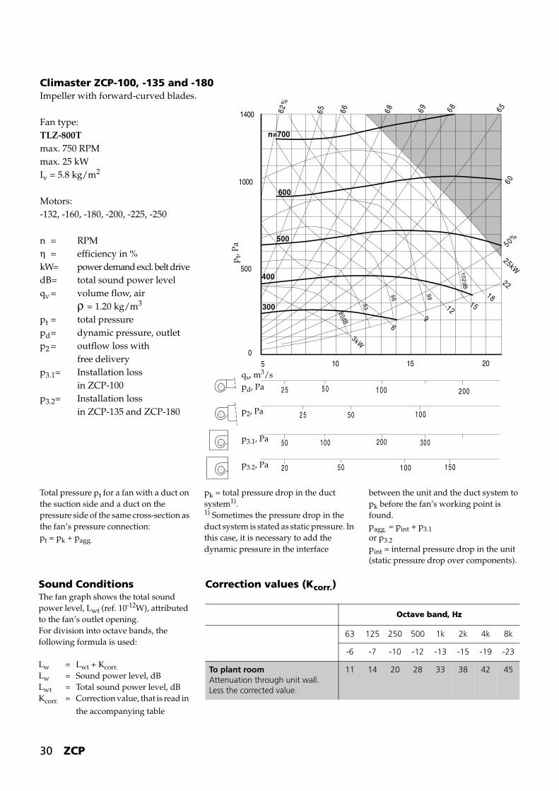
Climaster ZCP-100, -135 and -180Impeller with forward-curved blades.
Fan type:TLZ-800Tmax. 750 RPMmax. 25 kWIv = 5.8 kg/m2
Motors:-132, -160, -180, -200, -225, -250
n = RPMη = efficiency in %kW= power demand excl. belt drivedB= total sound power levelqv = volume flow, air
ρ = 1.20 kg/m3
pt = total pressurepd= dynamic pressure, outletp2 = outflow loss with
free deliveryp3.1= Installation loss
in ZCP-100p3.2= Installation loss
in ZCP-135 and ZCP-180
1400
1000
500
05 10 15 20
1 00 200
100
150100
5 0
1 0 0 200
50
5 0
30 05 0
2 5
2 5
20
3kW
69
1215
18
22
25kW
50%
60656869686662
%
n=700
600
500
400
300
102dB
9996
93
90 dB
65
p t, P
a
qv, m3/s
pd, Pa
p2, Pa
p3.1, Pa
p3.2, Pa
Correction values (Kcorr.)
Octave band, Hz
63 125 250 500 1k 2k 4k 8k
-6 -7 -10 -12 -13 -15 -19 -23
To plant roomAttenuation through unit wall.Less the corrected value.
11 14 20 28 33 38 42 45
Sound ConditionsThe fan graph shows the total sound power level, Lwt (ref. 10-12W), attributed to the fan’s outlet opening.For division into octave bands, the following formula is used:
Lw = Lwt + Kcorr.Lw = Sound power level, dBLwt = Total sound power level, dBKcorr. = Correction value, that is read in
the accompanying table
Total pressure pt for a fan with a duct on the suction side and a duct on the pressure side of the same cross-section as the fan’s pressure connection:pt = pk + pagg.
pk = total pressure drop in the duct system1).1) Sometimes the pressure drop in the duct system is stated as static pressure. In this case, it is necessary to add the dynamic pressure in the interface
between the unit and the duct system to pk before the fan’s working point is found.pagg. = pint + p3.1 or p3.2pint = internal pressure drop in the unit (static pressure drop over components).
ZCP 31
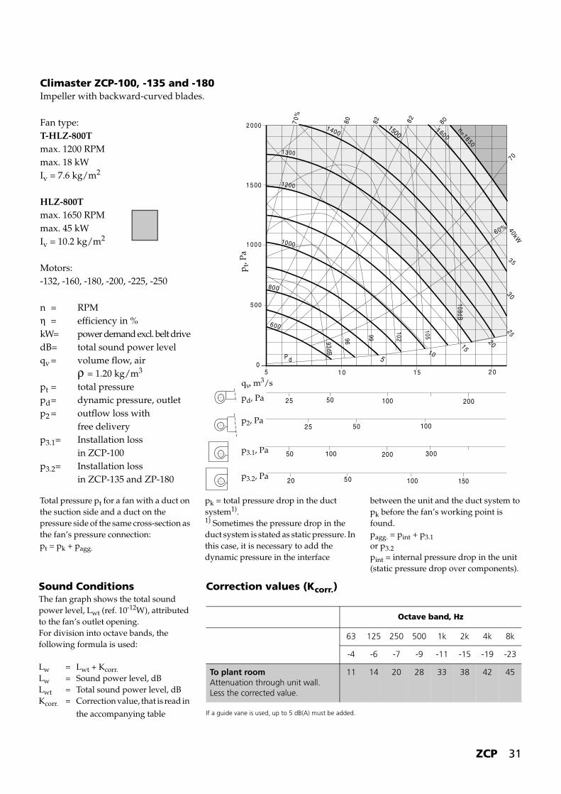
Climaster ZCP-100, -135 and -180Impeller with backward-curved blades.
Fan type:T-HLZ-800Tmax. 1200 RPMmax. 18 kWIv = 7.6 kg/m2
HLZ-800Tmax. 1650 RPMmax. 45 kWIv = 10.2 kg/m2
Motors:-132, -160, -180, -200, -225, -250
n = RPMη = efficiency in %kW= power demand excl. belt drivedB= total sound power levelqv = volume flow, air
ρ = 1.20 kg/m3
pt = total pressurepd= dynamic pressure, outletp2 = outflow loss with
free deliveryp3.1= Installation loss
in ZCP-100p3.2= Installation loss
in ZCP-135 and ZP-180
100 200
100
150100
50
100 200
50
50
30050
25
25
20
1 0 1 5 2 05
2 000
1500
1 00 0
500
05
10
15
20
2530
35
40kW
60%
70
8082828070%
n=1650
1 600
600
800
1000
12 00
14001500
1 3 00
P d
93dB
96
99
102
1 05
108dB
p t, P
a
qv, m3/s
pd, Pa
p2, Pa
p3.1, Pa
p3.2, Pa
Correction values (Kcorr.)
If a guide vane is used, up to 5 dB(A) must be added.
Octave band, Hz
63 125 250 500 1k 2k 4k 8k
-4 -6 -7 -9 -11 -15 -19 -23
To plant roomAttenuation through unit wall.Less the corrected value.
11 14 20 28 33 38 42 45
Sound ConditionsThe fan graph shows the total sound power level, Lwt (ref. 10-12W), attributed to the fan’s outlet opening.For division into octave bands, the following formula is used:
Lw = Lwt + Kcorr.Lw = Sound power level, dBLwt = Total sound power level, dBKcorr. = Correction value, that is read in
the accompanying table
Total pressure pt for a fan with a duct on the suction side and a duct on the pressure side of the same cross-section as the fan’s pressure connection: pt = pk + pagg.
pk = total pressure drop in the duct system1).1) Sometimes the pressure drop in the duct system is stated as static pressure. In this case, it is necessary to add the dynamic pressure in the interface
between the unit and the duct system to pk before the fan’s working point is found.pagg. = pint + p3.1 or p3.2pint = internal pressure drop in the unit (static pressure drop over components).
32 ZCP
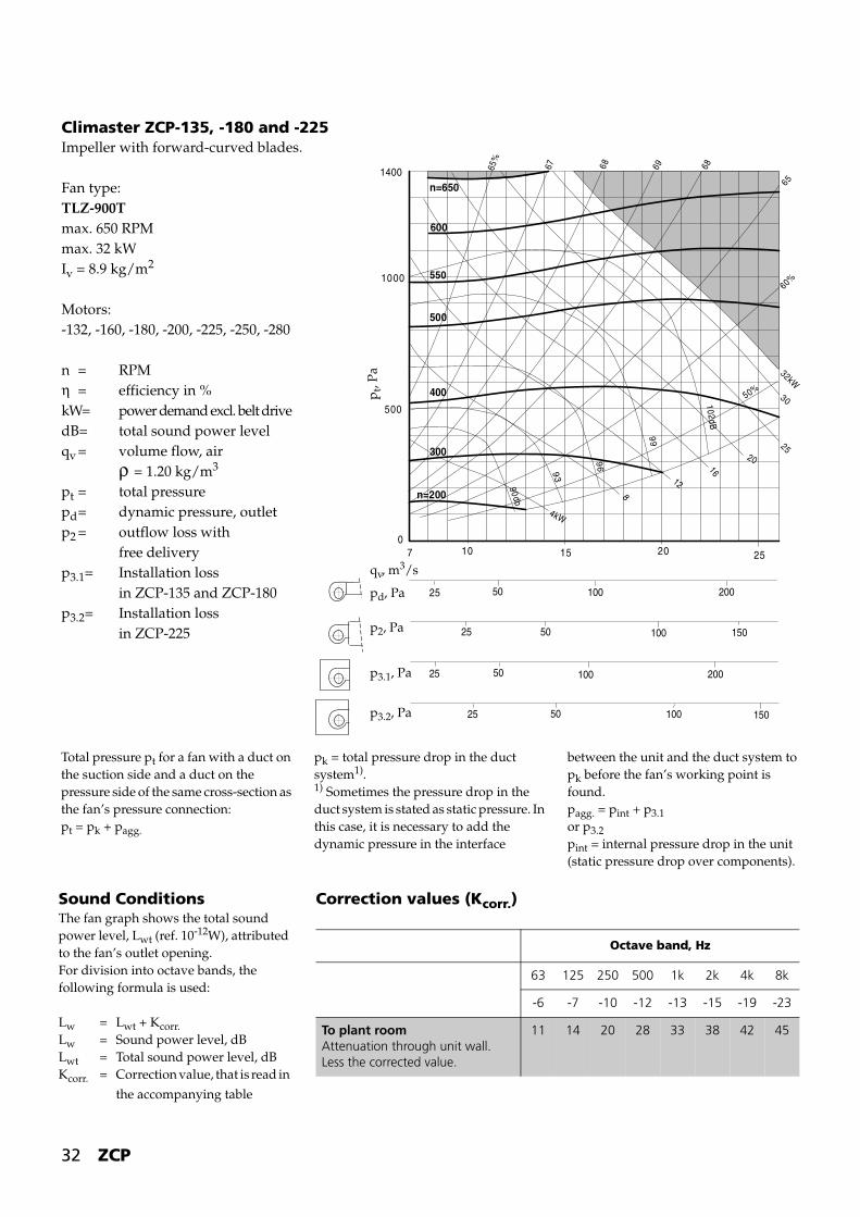
Climaster ZCP-135, -180 and -225Impeller with forward-curved blades.
Fan type:TLZ-900Tmax. 650 RPMmax. 32 kWIv = 8.9 kg/m2
Motors:-132, -160, -180, -200, -225, -250, -280
n = RPMη = efficiency in %kW= power demand excl. belt drivedB= total sound power levelqv = volume flow, air
ρ = 1.20 kg/m3
pt = total pressurepd= dynamic pressure, outletp2 = outflow loss with
free deliveryp3.1= Installation loss
in ZCP-135 and ZCP-180p3.2= Installation loss
in ZCP-225
1400
1000
500
07 10 15 20 25
65%
67 68 69 68
65
50%
60%
32kW
30
2520
16
12
8
4kW
n=200
300
400
500
550
600
n=650
90db
9 3
96
99
10 2dB
50 100 200
100
25
5025 150
100 2005025
100 1505025
p t, P
a
qv, m3/s
pd, Pa
p2, Pa
p3.1, Pa
p3.2, Pa
Correction values (Kcorr.)
Octave band, Hz
63 125 250 500 1k 2k 4k 8k
-6 -7 -10 -12 -13 -15 -19 -23
To plant roomAttenuation through unit wall.Less the corrected value.
11 14 20 28 33 38 42 45
Sound ConditionsThe fan graph shows the total sound power level, Lwt (ref. 10-12W), attributed to the fan’s outlet opening.For division into octave bands, the following formula is used:
Lw = Lwt + Kcorr.Lw = Sound power level, dBLwt = Total sound power level, dBKcorr. = Correction value, that is read in
the accompanying table
Total pressure pt for a fan with a duct on the suction side and a duct on the pressure side of the same cross-section as the fan’s pressure connection: pt = pk + pagg.
pk = total pressure drop in the duct system1).1) Sometimes the pressure drop in the duct system is stated as static pressure. In this case, it is necessary to add the dynamic pressure in the interface
between the unit and the duct system to pk before the fan’s working point is found.pagg. = pint + p3.1 or p3.2pint = internal pressure drop in the unit (static pressure drop over components).
ZCP 33
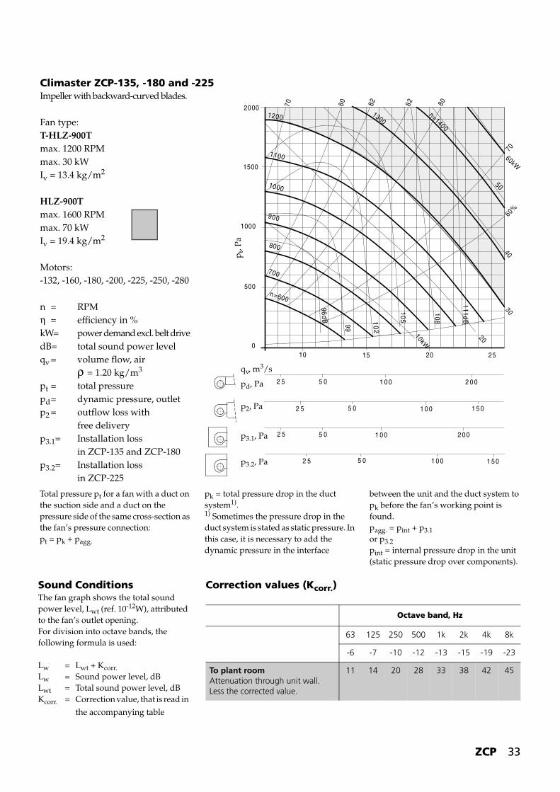
Climaster ZCP-135, -180 and -225Impeller with backward-curved blades.
Fan type:T-HLZ-900Tmax. 1200 RPMmax. 30 kWIv = 13.4 kg/m2
HLZ-900Tmax. 1600 RPMmax. 70 kWIv = 19.4 kg/m2
Motors:-132, -160, -180, -200, -225, -250, -280
n = RPMη = efficiency in %kW= power demand excl. belt drivedB= total sound power levelqv = volume flow, air
ρ = 1.20 kg/m3
pt = total pressurepd= dynamic pressure, outletp2 = outflow loss with
free deliveryp3.1= Installation loss
in ZCP-135 and ZCP-180p3.2= Installation loss
in ZCP-225
0
500
1000
1500
2000
10 20 2515
70
60%
8082828070
10kW
20
3040
50
60kW
n=1400
13001200
1100
1000
900
800
700
n=600
96d B
99
105
108
111dB
5 0 1 0 0 2 0 0
1 0 0
2 5
5 02 5 1 5 0
1 0 0 2005 02 5
1 0 0 1 5 05 02 5
102
p t, P
a
qv, m3/s
pd, Pa
p2, Pa
p3.1, Pa
p3.2, Pa
Correction values (Kcorr.)
Octave band, Hz
63 125 250 500 1k 2k 4k 8k
-6 -7 -10 -12 -13 -15 -19 -23
To plant roomAttenuation through unit wall.Less the corrected value.
11 14 20 28 33 38 42 45
Sound ConditionsThe fan graph shows the total sound power level, Lwt (ref. 10-12W), attributed to the fan’s outlet opening.For division into octave bands, the following formula is used:
Lw = Lwt + Kcorr.Lw = Sound power level, dBLwt = Total sound power level, dBKcorr. = Correction value, that is read in
the accompanying table
Total pressure pt for a fan with a duct on the suction side and a duct on the pressure side of the same cross-section as the fan’s pressure connection: pt = pk + pagg.
pk = total pressure drop in the duct system1).1) Sometimes the pressure drop in the duct system is stated as static pressure. In this case, it is necessary to add the dynamic pressure in the interface
between the unit and the duct system to pk before the fan’s working point is found.pagg. = pint + p3.1 or p3.2pint = internal pressure drop in the unit (static pressure drop over components).

34 ZCP
Climaster ZCP-180 and -225Impeller with forward-curved blades.
Fan type:TLZ 1000Tmax. 600 RPMmax. 40 kWIv = 13.5 kg/m2
Motors:-132, -160, -180, -200, -225, -250, -280
n = RPMη = efficiency in %kW= power demand excl. belt drivedB= total sound power levelqv = volume flow, air
ρ = 1.20 kg/m3
pt = total pressurepd= dynamic pressure, outletp2 = outflow loss with
free deliveryp3.1= Installation loss
in ZCP-180p3.2= Installation loss
in ZCP-22550
10 0 200
150100
5025 150
25
10 0 20050
50 15010025
300
10 15 20 25 30
1400
1000
500
0
200
300
400
450
500
n=550
65%
67 68 69 68
65
60%
90dB
93
96
9 9
102d B
6kW
12
18
25
30
35
40kW
p t, P
a
qv, m3/s
pd, Pa
p2, Pa
p3.1, Pa
p3.2, Pa
Correction values (Kcorr.)
Octave band, Hz
63 125 250 500 1k 2k 4k 8k
-6 -7 -10 -12 -13 -15 -19 -23
To plant roomAttenuation through unit wall.Less the corrected value.
11 14 20 28 33 38 42 45
Sound ConditionsThe fan graph shows the total sound power level, Lwt (ref. 10-12W), attributed to the fan’s outlet opening.For division into octave bands, the following formula is used:
Lw = Lwt + Kcorr.Lw = Sound power level, dBLwt = Total sound power level, dBKcorr. = Correction value, that is read in
the accompanying table
Total pressure pt for a fan with a duct on the suction side and a duct on the pressure side of the same cross-section as the fan’s pressure connection: pt = pk + pagg.
pk = total pressure drop in the duct system1).1) Sometimes the pressure drop in the duct system is stated as static pressure. In this case, it is necessary to add the dynamic pressure in the interface
between the unit and the duct system to pk before the fan’s working point is found.pagg. = pint + p3.1 or p3.2pint = internal pressure drop in the unit (static pressure drop over components).

ZCP 35
Climaster ZCP-180 and -225Impeller with backward-curved blades.
Fan type:T-HLZ-1000Tmax. 1065 RPMmax. 35 kWIv = 21.5 kg/m2
HLZ-1000Tmax. 1330 RPMmax. 70 kWIv = 29.5 kg/m2
Motors:-132, -160, -180, -200, -225, -250, -280
n = RPMη = efficiency in %kW= power demand excl. belt drivedB= total sound power levelqv = volume flow, air
ρ = 1.20 kg/m3
pt = total pressurepd= dynamic pressure, outletp2 = outflow loss with
free deliveryp3.1= Installation loss
in ZCP-180p3.2= Installation loss
in ZCP-225
50
100 200
150100
10 20 30
70%
80 82 82 80
70
60%
Pd
2000
1500
1000
500
010
20
30
40kW
96dB
9 9
105
108
111d B
n = 1300
12001100
1000
900
800
700
n = 600
5025 150
25
100 20050
50 15010025
300
5060kW
102
p t, P
a
qv, m3/s
pd, Pa
p2, Pa
p3.1, Pa
p3.2, Pa
Correction values (Kcorr.)
Octave band, Hz
63 125 250 500 1k 2k 4k 8k
-6 -7 -10 -12 -13 -15 -19 -23
To plant roomAttenuation through unit wall.Less the corrected value.
11 14 20 28 33 38 42 45
Sound ConditionsThe fan graph shows the total sound power level, Lwt (ref. 10-12W), attributed to the fan’s outlet opening.For division into octave bands, the following formula is used:
Lw = Lwt + Kcorr.Lw = Sound power level, dBLwt = Total sound power level, dBKcorr. = Correction value, that is read in
the accompanying table
Total pressure pt for a fan with a duct on the suction side and a duct on the pressure side of the same cross-section as the fan’s pressure connection: pt = pk + pagg.
pk = total pressure drop in the duct system1).1) Sometimes the pressure drop in the duct system is stated as static pressure. In this case, it is necessary to add the dynamic pressure in the interface
between the unit and the duct system to pk before the fan’s working point is found.pagg. = pint + p3.1 or p3.2pint = internal pressure drop in the unit (static pressure drop over components).

Novenco develops and manufactures
ventilation and fi re fi ghting systems that
are marketed and distributed world-wide
through subsidiaries and agents.
The company was founded in Denmark
1947 and has become one of the
world-leading suppliers.
Novenco symbolises quality and environ-
mentally friendly products. The company
is certifi ed according to ISO 9001 and
ISO 14001.
The headquarters of Novenco is located
in Naestved, Denmark.
Novenco, Hi-Pres and XFlow are
registered trademarks of Novenco.
Read more about Novenco on the
Internet.
Novenco A/S · Industrivej 22 · DK-4700 Naestved · Denmark · Tel. +45 70 12 42 22 · Fax +45 55 75 65 50
www.novenco-group.com
MU
13947 0
6.0
5


![˘ˇ ˆ˙ - Kitamoto · q&Nr / ast/su/sv Lwxy/z{˝q& |.}E ˝˝~- 00 TA6 •:7(0 †‡ N: "…—7& ’N /–Tƒ⁄‹›]− XY: ‹›:P%& ... fi-fl+˙ZCP%&](https://static.fdocuments.us/doc/165x107/5be4aa6e09d3f2f4628d0114/-qnr-astsusv-lwxyzq-e-00-ta6-70-n.jpg)