Applied Instructions - xlogicusa.com · 4 applied instructions 4 ... ZCP Compare the data in...
93
4 applied instructions 4 Applied Instructions In this chapter, we describe applied instruction’s function of XC series PLC. 4-1.Table of Applied Instructions 4-2.Reading Method of Applied Instructions 4-3.Flow Instructions 4-4.Contactors Compare Instructions 4-5.Move Instructions 4-6.Arithmetic and Logic Operation Instructions 4-7.Loop and Shift Instructions 4-8.Data Convert 4-9.Floating Operation 4-10.Clock Operation
Transcript of Applied Instructions - xlogicusa.com · 4 applied instructions 4 ... ZCP Compare the data in...

4 applied instructions
4 Applied Instructions In this chapter, we describe applied instruction’s function of XC series PLC.
4-1.Table of Applied Instructions
4-2.Reading Method of Applied Instructions
4-3.Flow Instructions
4-4.Contactors Compare Instructions
4-5.Move Instructions
4-6.Arithmetic and Logic Operation Instructions
4-7.Loop and Shift Instructions
4-8.Data Convert
4-9.Floating Operation
4-10.Clock Operation

4 applied instructions

4 applied instructions
4-1.Applied Instruction List
Mnemonic Function Ladder chart Chapter
Program Flow
CJ Condition jump CJ Pn
4-3-1
CALL Call subroutine CALL Pn
4-3-2
SRET Subroutine return SRET
4-3-2
STL Flow start STL Sn
4-3-3
STLE Flow end S 1 ·
4-3-3
SET Open the assigned flow, close
the current flow S ·
4-3-3
ST Open the assigned flow, not
close the current flow D ·
4-3-3
FOR Start a FOR-NEXT loop D ·
4-3-4
NEXT End of a FOR-NEXT loop D ·
4-3-4
FEND Main program END D ·
4-3-5
END Program END
4-3-5
Data Compare
LD= LD activates if (S1) = (S2) S ·
4-4-1
LD> LD activates if (S1) > (S2) D ·
4-4-1
LD< LD activates if (S1) =< (S2) D ·
4-4-1
LD<> LD activates if(S1)≠(S2) D ·
4-4-1
LD<= LD activates if(S1)≤(S2) D ·
4-4-1
LD>= LD activates if(S1)≥(S2) LD>= S1 S2
4-4-1
AND= AND activates if(S1)=(S2) AND= S1 S2
4-4-2

4 applied instructions
AND> AND activates if(S1)>(S2) AND> S1 S2
4-4-2
AND< AND activates if(S1)<(S2) AND< S1 S2
4-4-2
AND<> AND activates if(S1)≠(S2) AND<> S1 S2
4-4-2
AND<= AND activates if(S1)≤(S2) AND<= S1 S2
4-4-2
AND>= AND activates if(S1)≥(S2) B M O V D 1 0 D 1 1 K 3
B M O V D 1 0 D 9 K 3X 1
X 2
4-4-2
OR= OR activates if(S1)=(S2) OR= S1 S2
4-4-3
OR> OR activates if(S1)>(S2) PMOV D5 D10 K3
X0nS· D·
4-4-3
OR< OR activates if(S1)<(S2) OR< S1 S2
4-4-3
OR<> OR activates if(S1)≠(S2) OR<> S1 S2
4-4-3
OR<= OR activates if(S1)≤(S2) DFMOV D0 D10 K3
X0nS· D·
4-4-3
OR>= OR activates if(S1)≥(S2) OR>= S1 S2
4-4-3
Data Move
CMP Compare the data CMP S1 S D
4-5-1
ZCP Compare the data in certain area D 0F W R T F D 0X 2
K 3
S · D 1 · D 2 ·
4-5-2
MOV Move MOV S D
4-5-3
BMOV Block move M S E T M 1 0 M 1 2 0
D 1 · D 2 ·X 0
4-5-4
PMOV Transfer the Data block D 2 ·
4-5-5
FMOV Multi-points repeat move D 1 ·
4-5-6
FWRT Flash ROM written D 2 ·
4-5-7
MSET Zone set D 1 ·
4-5-8
ZRST Zone reset D 2 ·
4-5-9
SWAP Swap the high and low byte D 1 ·
4-5-10
4 applied instructions
XCH Exchange two values Z R S T M 5 0 0 M 5 5 9
D 0 D 1 0 0
D 1 · D 2 ·
D 1 · D 2 ·
X 0
Z R S T 4-5-11
EMOV Float move
4-5-12
Data Operation
ADD Addition D 2 ·
4-6-1
SUB Subtraction D 1 ·
4-6-2
MUL Multiplication D 2 ·
4-6-3
DIV Division D 1 ·
4-6-4
INC Increment D 1 ·
4-6-5
DEC Decrement D 2 ·
4-6-5
MEAN Mean D 1 ·
4-6-6
WAND Word And WAND S1 S2 D
4-6-7
WOR Word OR WOR S1 S2 D
4-6-7
WXOR Word exclusive OR WXOR S1 S2 D
4-6-7
CML Compliment CML S D
4-6-8
NEG Negative
4-6-9
Data Shift
SHL Arithmetic Shift Left SHL D n
4-7-1
SHR Arithmetic Shift Right SHR D n
4-7-1
LSL Logic shift left
4-7-2
LSR Logic shift right
4-7-2
ROL Rotation shift left
4-7-3
ROR Rotation shift right
4-7-3

4 applied instructions
SFTL Bit shift left SFTL S D n1 n2
4-7-4
SFTR Bit shift right SFTR S D n1 n2
4-7-5
WSFL Word shift left
4-7-6
WSFR Word shift right
4-7-7
Data Convert
WTD Single word integer converts
to double word integer WTD S D
4-8-1
FLT 16 bits integer converts to
float point 4-8-2
DFLT 32 bits integer converts to float point
4-8-2
FLTD 64 bits integer converts to
float point 4-8-2
INT Float point converts to integer
4-8-3
BIN BCD converts to binary
4-8-4
BCD Binary converts to BCD
4-8-5
ASCI Hex. converts to ASCII ASCI S D n
4-8-6
HEX ASCII converts to Hex.
4-8-7
DECO Coding
4-8-8
ENCO High bit coding
4-8-9
ENCOL Low bit coding
4-8-10
Float Point Operation
ECMP Float compare ECMP S1 S2 D
4-9-1
EZCP Float Zone compare EZCP S1 S2 D1 D2
4-9-2

4 applied instructions
EADD Float Add
4-9-3
ESUB Float Subtract
4-9-4
EMUL Float Multiplication
4-9-5
EDIV Float division
4-9-6
ESQR Float Square Root
4-9-7
SIN Sine
4-9-8
COS Cosine
4-9-9
TAN Tangent
4-9-10
ASIN Floating Sine
4-9-11
ACOS Floating Cosine
4-9-12
ATAN Floating Tangent
4-9-13
Clock Operation
TRD Read RTC data
4-10-1
TWR Write RTC data
4-10-2

4 applied instructions
4-2.Reading Method of Applied Instructions In this manual, the applied instructions are described in the following manner. 1.Summary
ADDITION [ADD]
16 bits ADD 32 bits DADD
Execution
condition
Normally ON/OFF, Rising/Falling
edge
Suitable
Models
XC1.XC2.XC3.XC5.XCM
Hardware
requirement
- Software
requirement
-
2.Operands
Operands Function Data Type
S1 Specify the augend data or register 16 bits/32 bits, BIN
S2 Specify the summand data or register 16 bits/32 bits, BIN
D Specify the register to store the sum 16 bits/32 bits, BIN
3.Suitable Soft Components
<16 bits instruction>
ADD D10 D12 D14X0
S1· S2· D·
<32 bits instruction>
DADD D10 D12 D14X0
S1· S2· D·
Word operands System Constant Module
D FD ED TD CD DX DY DM DS K /H ID QD
S1 ● ● ● ● ● ● ● ● ●
S2 ● ● ● ● ● ● ● ● ●
D ● ● ● ● ● ● ●
Bit Operands System
X Y M S T C Dn.m
Description
(D10)+(D12)→(D14)
(D11D10)+(D13D12)→(D15D14)

4 applied instructions
The data contained within the two source devices are combined and total is stored in the specified
destination device. Each data’s highest bit is the sign bit, 0 stands for positive, 1 stand for negative. All
calculations are algebraic processed. (5+(-8)= -3).
If the result of a calculations is “0”, the “0’ flag acts. If the result exceeds 323,767(16 bits limit) or
2,147,483,648 ( 32 bits limit), the carry flag acts. ( refer to the next page). If the result exceeds -323,768 (16
bits limit) or -2,147,483,648 (32 bits limit ) , the borrow flag acts (Refer to the next page)
When carry on 32 bits operation, word device’s 16 bits are assigned, the device follow closely the preceding
device’s ID will be the high bits. To avoid ID repetition, we recommend you assign device’s ID to be even
ID.
The same device may be used a source and a destination. If this is the case then the result changes after
every scan cycle. Please note this point.
Flag Name Function
M8020 Zero ON:the calculate result is zero
OFF:the calculate result is not zero
M8021 Borrow
ON:the calculate result is over 32767(16bits) or 2147483647(32bits)
OFF:the calculate result is not over 32767(16bits) or 2147483647(32bits)
M8022 Carry
ON:the calculate result is over 32767(16bits) or 2147483647(32bits)
OFF:the calculate result is not over 32767(16bits) or 2147483647(32bits)
Instruction D(NUM) Object data
Related flag
The assignment of the data The data register of XC series PLC is a single word (16 bit) data register, single word data only engross one data register which is assigned by single word object instruction. The disposal bound is: Dec. –327,68~327,67, Hex. 0000~FFFF.
The related
description
D(NUM) Single word object instruction
→
Double word(32 bit)engrosses two data register, it’s composed by two consecutive data registers, the first one is assigned by double word object instruction. The dispose bound is: Dec. -214,748,364,8~214,748,364,7, Hex. 00000000~FFFFFFFF.

4 applied instructions
Instruction D(NUM) Object data Object data
※1:Flag after executing the instruction. Instructions without the direct flag will not display. ※2: Source operand, its content won’t change after executing the instruction
※3: Destinate operand, its content changes with the execution of the instruction ※4:Tell the instruction’s basic action, using way, applied example, extend function, note items etc. 4-3.Program Flow Instructions
Mnemonic Instruction’s name Chapter CJ Condition Jump 4-3-1 CALL Call subroutine 4-3-2 SRET Subroutine return 4-3-2 STL Flow start 4-3-3 STLE Flow end 4-3-3 SET Open the assigned flow, close the current flow (flow
jump) 4-3-3
ST Open the assigned flow, not close the current flow (Open the new flow)
4-3-3
FOR Start of a FOR-NEXT loop 4-3-4 NEXT End of a FOR-NEXT loop 4-3-4 FEND First End 4-3-5 END Program End 4-3-5
D(NUM+1) D(NUM) Double word object instruction
→
The denote way of 32 bits instruction If an instruction can not only be 16 bits but also be 32 bits, then the denote method for 32 bits instruction is to add a “D” before 16 bits instruction. E.g:ADD D0 D2 D4 denotes two 16 bits data adds;
DADD D10 D12 D14 denotes two 32 bits data adds
S·
D·

4 applied instructions
4-3-1.Condition Jump [CJ] 1.Summary
As used to run a part of program, CJ shorten the operation cycle and using the dual coil Condition Jump [CJ] 16 bits CJ 32 bits - Execution
condition
Normally ON/OFF coil Suitable
Models
XC1.XC2.XC3.XC5.XCM
Hardware
requirement
- Software
requirement
-
2.Operands
Operands Function Data Type
Pn Jump to the target (with pointer Nr.) P (P0~P9999) Pointer's Nr. 3.Suitable Soft Components
In the below graph, if X000 is “ON”, jump from the first step to the next step behind P6 tag. If X000 “OFF”, do not execute the jump construction;
Pointer
P I
●
Other
Description

4 applied instructions
CJ
Y0
X0
X1
X3
X4
X0
RST
T246 K1000
MOV
CJ
X2
X5
X6
P6
T246
K3 D0
P7
T246RST
Y0
P6
P7
4-3-2.Call subroutine [CALL] and Subroutine return [SRET]
1.Summary Call the programs which need to be executed together, decrease the program's steps;
Subroutine Call [CALL] 16 bits CALL 32 bits - Execution
condition
Normally ON/OFF, Rising/Falling edge
Suitable
Models
XC1.XC2.XC3.XC5.XCM
Hardware
requirement
- Software
requirement
-
Subroutine Return [SRET] 16 bits SRET 32 bits - Execution
condition
- Suitable
Models
XC1.XC2.XC3.XC5.XCM
Hardware
requirement
- Software
requirement
-
2.Operands
Operands Function Data Type
Pn Jump to the target (with pointer Nr.) P (P0~P9999) Pointer's Nr. 3.Suitable Soft Components
In the left graph, Y000 becomes to be dual coil output, but when X000=OFF, X001 activates; when X000=ON, X005 activates
CJ can’t jump from one STL to another STL;
After driving time T0~T640 and HSC C600~C640, if execute CJ, continue to work, the output activates.

4 applied instructions
CALLX0
FEND
SRET
END
P10
P10
4-3-3.Flow [SET].[ST] .[STL]. [STLE]
1、Summary Instructions to specify the start, end, open, close of a flow;
Open the specified flow, close the local flow [SET] 16 bits SET 32 bits - Execution
condition
Normally ON/OFF, Rising/Falling edge
Suitable
Models
XC1.XC2.XC3.XC5.XCM
Hardware
requirement
- Software
requirement
-
Open the specified flow, not close the local flow [ST] 16 bits ST 32 bits - Execution
condition
Normally ON/OFF, Rising/Falling edge
Suitable
Models
XC1.XC2.XC3.XC5.XCM
Hardware
requirement
- Software
requirement
-
Flow starts [STL] 16 bits STL 32 bits -
Others Pointer
P I
●
Main Program
Subroutine
If X000= “ON”, execute the call instruction and jump to the step tagged by P10. after executing the subroutine, return the original step via SRET instruction.Program the tag with FEND instruction (will describe this instruction later)
In the subroutine 9 times call is allowed, so totally there can be 10 nestings.
Description

4 applied instructions
Execution
condition
- Suitable
Models
XC1.XC2.XC3.XC5.XCM
Hardware
requirement
- Software
requirement
-
Flow ends [STLE] 16 bits STLE 32 bits - Execution
condition
- Suitable
Models
XC1.XC2.XC3.XC5.XCM
Hardware
requirement
- Software
requirement
-
2.operands
Operands Function Data Type
Sn Jump to the target flow S Flow ID 3.Suitable Soft Components
Operands System
X Y M S T C Dn.m
Sn ●
Bit
Description
STL and STLE should be used in pairs. STL represents the start of a flow, STLE represents the end of a flow.
After executing of SET Sxxx instruction, the flow specified by these instructions is ON. After executing RST Sxxx instruction, the specified flow is OFF. In flow S0, SET S1 close the current flow S0, open flow S1. In flow S0, ST S2 open the flow S2, but don’t close flow S0. When flow turns from ON to be OFF, reset OUT、PLS、PLF、not accumulate timer etc.
which belongs to the flow. ST instruction is usually used when a program needs to run more flows at the same time. After executing of SET Sxxx instruction, the pulse instructions will be closed (including
one-segment, multi-segment, relative or absolute, return to the origin)

4 applied instructions
SET S0
STL S0
SET S1
ST S2
STL S1
STLE
STLE
STL S2
STLE

4 applied instructions
4-3-4. [FOR] and [NEXT] 1.Summary Loop execute the program between FOR and NEXT with the specified times;
Loop starts [FOR] 16 bits FOR 32 bits - Execution
condition
Rising/Falling edge Suitable
Models
XC1.XC2.XC3.XC5.XCM
Hardware
requirement
- Software
requirement
-
Loop ends [NEXT] 16 bits NEXTs 32 bits - Execution
condition
Normally ON/OFF, Rising/Falling edge
Suitable
Models
XC1.XC2.XC3.XC5.XCM
Hardware
requirement
- Software
requirement
-
2.Operands
Operands Function Data Type
S Program’s loop times between FOR~NEXT 16 bits, BIN 3.Suitable Soft Components
FOR.NEXT instructions must be programmed as a pair. Nesting is allowed, and the nesting
level is 8. Between FOR/NEXT, LDP.LDF instructions are effective for one time. Every time when M0
turns from OFF to ON, and M1 turns from OFF to ON, [A] loop is executed 6 times. Every time if M0 turns from OFF to ON and M3 is ON, [B] loop is executed 5×7=35 times. If there are many loop times, the scan cycle will be prolonged. Monitor timer error may
occur, please note this. If NEXT is before FOR, or no NEXT, or NEXT is behind FENG,END, or FOR and NEXT
number is not equal, an error will occur. Between FOR~NEXT, CJ nesting is not allowed, also in one STL, FOR~NEXT must be
programmed as a pair.
Operands System Constant Module
D FD ED TD CD DX DY DM DS K /H ID QD
S ● ●
Word
Description

4 applied instructions
F O R K 6
IN C D 0
N E X T
F O R K 7
IN C D 1
N E X T
N E X T
F O R K 5M 0
M 3
M 1
[A ]
[B ]
[C ]
S ·
4-3-5. [FEND] and [END] 1.Summary FEND means the main program ends, while END means program ends;
main program ends [FEND] Execution condition - Suitable Models XC1.XC2.XC3.XC5.XCM Hardware requirement - Software requirement - program ends [END] Execution condition - Suitable Models XC1.XC2.XC3.XC5.XCM Hardware requirement - Software requirement -
2.Operands
Operands Function Data Type
None - - 3.Suitable Soft Components
Even though [FEND] instruction represents the end of the main program, if execute this instruction, the function is same with END. Execute the output/input disposal, monitor the refresh of the timer, return to the 0th step.
None
Description

4 applied instructions
If program the tag of CALL instruction behind FEND instruction, there must be SRET instruction. If the interrupt pointer program behind FEND instruction, there must be IRET instruction.
After executing CALL instruction and before executing SRET instruction, if execute FEND instruction; or execute FEND instruction after executing FOR instruction and before executing NEXT, then an error will occur.
In the condition of using many FEND instruction, please compile routine or subroutine between the last FEND instruction and END instruction.
4-4. Data compare function
Mnemonic Function Chapter LD= LD activates when(S1)=(S2) 4-4-1 LD> LD activates when(S1)>(S2) 4-4-1 LD< LD activates when(S1)<(S2) 4-4-1 LD<> LD activates when(S1)≠(S2) 4-4-1 LD<= LD activates when(S1)≤(S2) 4-4-1 LD>= LD activates when(S1)≥(S2) 4-4-1 AND= AND activates when(S1)=(S2) 4-4-2 AND> AND activates when(S1)>(S2) 4-4-2 AND< AND activates when(S1)<(S2) 4-4-2 AND<> AND activates when(S1)≠(S2) 4-4-2 AND<= AND activates when(S1)≤(S2) 4-4-2 AND>= AND activates when(S1)≥(S2) 4-4-2
4 applied instructions
OR= OR activates when(S1)=(S2) 4-4-3 OR> OR activates when(S1)>(S2) 4-4-3 OR< OR activates when(S1)<(S2) 4-4-3 OR<> OR activates when(S1)≠(S2) 4-4-3 OR<= OR activates when(S1)≤(S2) 4-4-3 OR>= OR activates when(S1)≥(S2) 4-4-3
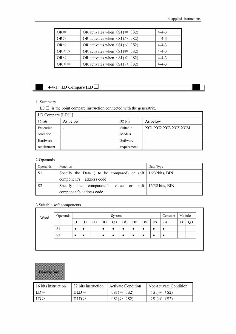
4-4-1.LD Compare [LD□]
1. Summary
LD□ is the point compare instruction connected with the generatrix. LD Compare [LD□] 16 bits As below 32 bits As below Execution
condition
- Suitable
Models
XC1.XC2.XC3.XC5.XCM
Hardware
requirement
- Software
requirement
-
2.Operands
Operands Function Data Type
S1 Specify the Data ( to be compared) or soft component’s address code
16/32bits, BIN
S2 Specify the comparand’s value or soft component’s address code
16/32 bits, BIN
3.Suitable soft components 16 bits instruction 32 bits instruction Activate Condition Not Activate Condition LD= DLD= (S1)=(S2) (S1)≠(S2) LD> DLD> (S1)>(S2) (S1)≤(S2)
Operands System Constant Module
D FD ED TD CD DX DY DM DS K /H ID QD
S1 ● ● ● ● ● ● ● ● ●
S2 ● ● ● ● ● ● ● ● ●
Word
Description

4 applied instructions
LD< DLD< (S1)<(S2) (S1)≥(S2) LD<> DLD<> (S1)≠(S2) (S1)=(S2) LD<= DLD<= (S1)≤(S2) (S1)>(S2) LD>= DLD>= (S1)≥(S2) (S1)<(S2)
LD> D200 K-30 SET Y1
DLD> K68899 C300 M50
X1
M4
S1· S2·
LD= K100 C0 Y0X0
4-4-2.AND Compare [AND□] 1.Summary
AND□: The compare instruction to serial connect with the other contactors. AND Compare [AND□] 16 bits As Below 32 bits As Below Execution
condition
Normally ON/OFF coil Suitable
Models
XC1.XC2.XC3.XC5.XCM
Hardware
requirement
- Software
requirement
-
2.Operands
Operands Function Data Type
S1 Specify the Data ( to be compared) or soft component’s address code
16/32bit,BIN
S2 Specify the comparand’s value or soft component’s address code
16/32bit,BIN
3.suitable soft components
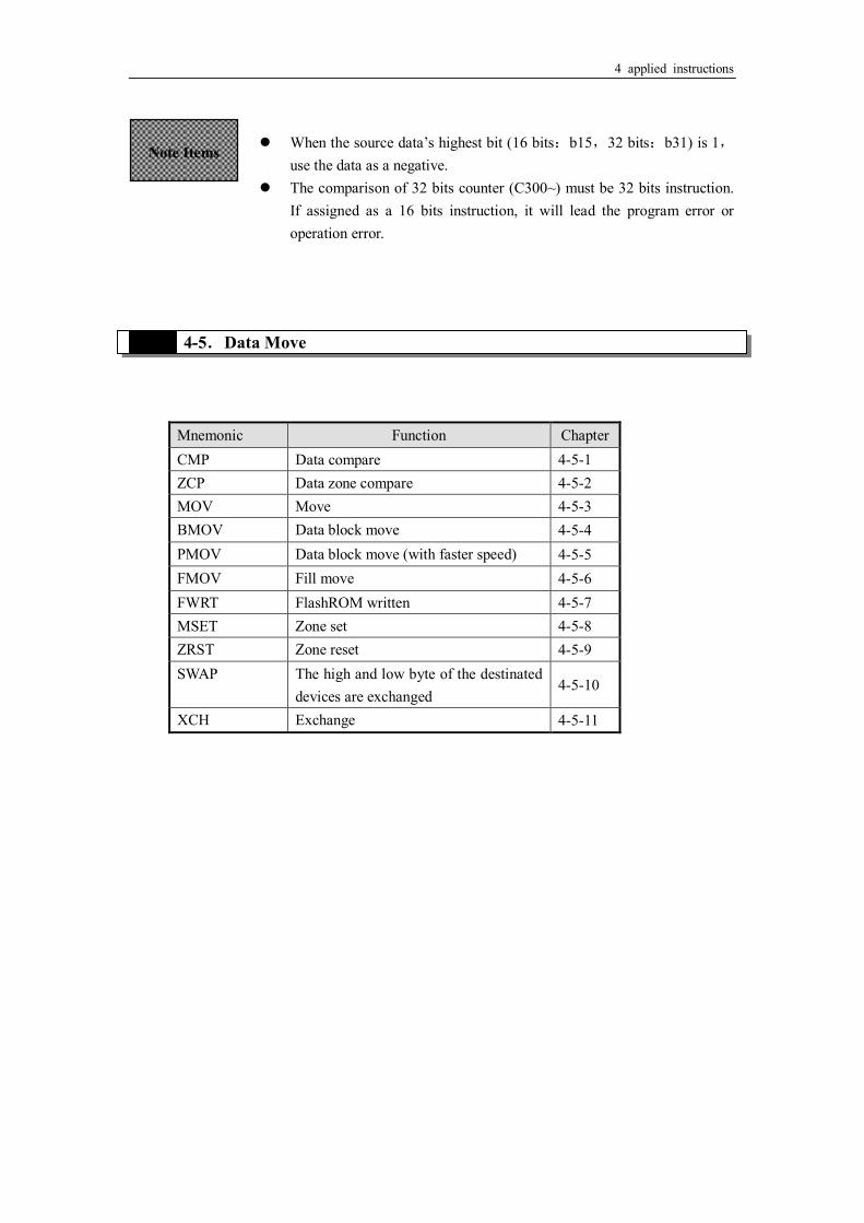
When the source data’s highest bit (16 bits:b15,32 bits:b31) is 1,use the data as a negative.
The comparison of 32 bits counter (C300~) must be 32 bits instruction. If assigned as a 16 bits instruction, it will lead the program error or operation error.
。
Note Items
Operands System Konstant Module
D FD ED TD CD DX DY DM DS K /H ID QD
S1 ● ● ● ● ● ● ● ● ●
S2 ● ● ● ● ● ● ● ● ●
Word

4 applied instructions
16 bits instruction 32 bits instruction Activate Condition Not Activate Condition AND= DAND= (S1)=(S2) (S1)≠(S2) AND> DAND> (S1)>(S2) (S1)≤(S2) AND< DAND< (S1)<(S2) (S1)≥(S2) AND<> DAND<> (S1)≠(S2) (S1)=(S2) AND<= DAND<= (S1)≤(S2) (S1)>(S2) AND>= DAND>= (S1)≥(S2) (S1)<(S2)
AND= K100 C0 Y0
AND> D0K-30 SET Y1
DAND> K68899 D10 M50
X1
M4
X0
X2
S1· S2·
4-4-3.Parallel Compare [OR□] 1. Summary
OR□ The compare instruction to parallel connect with the other contactors Parallel Compare [OR□] 16 bits As below 32 bits As below Execution - Suitable XC1.XC2.XC3.XC5.XCM
Description
When the source data’s highest bit (16 bits:b15,32 bits:b31) is 1,use the data as a negative.
The comparison of 32 bits counter (C300~) must be 32 bits instruction. If assigned as a 16 bits instruction, it will lead the program error or operation error.
Note Items

4 applied instructions
condition Models
Hardware
requirement
- Software
requirement
-
2. Operands
Operands Function Data Type
S1 Specify the Data ( to be compared) or soft component’s address code
16/32 bit,BIN
S2 Specify the comparand’s value or soft component’s address code
16/32 bit,BIN
3. suitable soft components 16 bits instruction 32 bits instruction Activate Condition Not Activate Condition OR= DOR= (S1)=(S2) (S1)≠(S2) OR> DOR> (S1)>(S2) (S1)≤(S2) OR< DOR< (S1)<(S2) (S1)≥(S2) OR<> DOR<> (S1)≠(S2) (S1)=(S2) OR<= DOR<= (S1)≤(S2) (S1)>(S2) OR>= DOR>= (S1)≥(S2) (S1)<(S2)
OR= K100 C0
Y0
DOR> K68899D10
M50M4
X0
X2
S1· S2·
Operands System Constant Module
D FD ED TD CD DX DY DM DS K /H ID QD
S1 ● ● ● ● ● ● ● ● ●
S2 ● ● ● ● ● ● ● ● ●
Word
Description
4 applied instructions
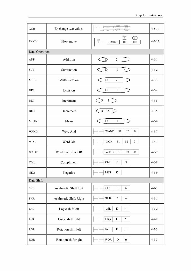
4-5.Data Move
Mnemonic Function Chapter CMP Data compare 4-5-1 ZCP Data zone compare 4-5-2 MOV Move 4-5-3 BMOV Data block move 4-5-4 PMOV Data block move (with faster speed) 4-5-5 FMOV Fill move 4-5-6 FWRT FlashROM written 4-5-7 MSET Zone set 4-5-8 ZRST Zone reset 4-5-9 SWAP The high and low byte of the destinated
devices are exchanged 4-5-10
XCH Exchange 4-5-11
When the source data’s highest bit (16 bits:b15,32 bits:b31) is 1,use the data as a negative.
The comparison of 32 bits counter (C300~) must be 32 bits instruction. If assigned as a 16 bits instruction, it will lead the program error or operation error.
Note Items

4 applied instructions
4-5-1.Data Compare [CMP] 1. Summary
Compare the two specified Data, output the result. Data compare [CMP] 16 bits CMP 32 bits DCMP Execution
condition
Normally ON/OFF, rising/falling edge
Suitable
Models
XC1.XC2.XC3.XC5.XCM
Hardware
requirement
- Software
requirement
-
2. Operands
Operands Function Data Type
S1 Specify the data (to be compared) or soft component’s address code
16 bit,BIN
S Specify the comparand’s value or soft component’s address code
16 bit,BIN
D Specify the compare result’s address code bit 3. Suitable soft component
CMP D10 D20 M0
S1·
X0
M0
M1
M2
D10 > D20
S·
D10 = D20
D10 < D20
ON
ON
ON
D
Word Operands System Constant Module
D FD ED TD CD DX DY DM DS K /H ID QD
S1 ● ● ● ● ● ● ● ● ●
S ● ● ● ● ● ● ● ● ●
Oper
ands
System
X Y M S T C Dn..m
D ● ● ●
Bit
Description
Even X000=OFF to stop ZCP instruction, M0~M2 will
keep the original status Compare data and , output the three points’ ON/OFF status (start with ) according to the value
S1· S·
D·

4 applied instructions
4-5-2.Data zone compare [ZCP] 1. Summary
Compare the two specify Data with the current data, output the result. Data Zone compare [ZCP] 16 bits ZCP 32 bits DZCP Execution
condition
Normally ON/OFF, rising/falling edge
Suitable
Models
XC1.XC2.XC3.XC5.XCM
Hardware
requirement
- Software
requirement
-
2. Operands
Operands Function Data Type
S1 Specify the down-limit Data (of the compare stand) or soft component’s address code
16 bit, BIN
S2 Specify the Up-limit Data (of the compare stand) or soft component’s address code
16 bit, BIN
S Specify the current data or soft component’s address code
16 bit, BIN
D Specify the compare result’s data or soft component’s address code
bit
3.Suitable soft components
, +1, +2 :the three point’s on/off output according to the valve D· D· D·
Word Operands System Constant Module
D FD ED TD CD DX DY DM DS K /H ID QD
S1 ● ● ● ● ● ● ● ● ●
S2 ● ● ● ● ● ● ● ● ●
S ● ● ● ● ● ● ● ● ●
Bit Oper
ands
System
X Y M S T C Dn..m
D ● ● ●

4 applied instructions
4-5-3.MOV [MOV]
ZCP D20 D30 D0 M0
S1· S2· S· D·
X0
M0
M1
M2
D0 M0 ON
M1 ON
M2 ON
D0
D0
D20
D20 D31(分)
D31(分)
>
≤ ≤
>
1. Summary
Move the specified data to the other soft components MOV [MOV] 16 bits MOV 32 bits DMOV Execution
condition
Normally ON/OFF, rising/falling edge
Suitable
Models
XC1.XC2.XC3.XC5.XCM
Hardware
requirement
- Software
requirement
-
2. Operands
Operands Function Data Type
S Specify the source data or register’s address code 16 bit/32 bit, BIN D Specify the target soft component’s address code 16 bit/32 bit, BIN
3. Suitable soft component
Even X000=OFF stop ZCP instruction,M0~M2 will keep
the original status
Description
Compare data with and , output the three point’s ON/OFF status according to the zone size.
, +1, +2 : the three point’s ON/OFF output according to the result
S· D·
D·D·D·
Word Operands System Constant Module
D FD ED TD CD DX DY DM DS K /H ID QD
S ● ● ● ● ● ● ● ● ● ●
D ● ● ● ● ● ● ●
S1 S2

4 applied instructions
MOV K10 D10X0
S· D·
<read the counter’s or time’s current value> <indirectly specify the counter’s ,time’s set value>
MOV T0 D20X1
MOV K10 D20X2
M0T20 D20
< Move the 32bits data >
DMOV D0 D10
DMOV C235 D20
Description Move the source data to the target When X000 is off, the data keeps
same Convert constant K10 to be BIN
code automatically
(K10)(D10)
D20=K10 ( The current value of T0)→(D20)
The same as counter
Please use DMOV when the value is 32 bits, such as MUL instruction, high speed counter…
(D1,D0)→(D11,D10)
(the current value of C235)→(D21,D20)

4 applied instructions
4-5-4.Data block Move [BMOV] 1. Summary
Move the specified data block to Data block move [BMOV] 16 bits BMOV 32 bits - Execution
condition
Normally ON/OFF coil Suitable
Models
XC1.XC2.XC3.XC5.XCM
Hardware
requirement
- Software
requirement
-
2. Operands
Operands Function Data Type
S Specify the source data block or soft component address code
16 bits, BIN; bit
D Specify the target soft components address code 16 bits, BIN; bit n Specify the move data’s number 16 bits, BIN;
3. Suitable soft components
Move the specified “n” data to the specified “n” soft components in the form block.
BMOV D5 D10 K3X0
nS· D·
D5
D6
D7
D10
D11
D12
n=3
Operands System Constant Module
D FD ED TD CD DX DY DM DS K /H ID QD
S ● ● ● ● ● ● ● ● ●
D ● ● ● ● ● ● ●
n ● ● ● ● ● ● ●
Word
Bit Operands System
X Y M S T C Dn.m
S ● ● ●
D ● ● ●
Description

4 applied instructions
As the following picture, when the data address overlapped, the instruction will do from 1 to 3.
BMOV D10 D11 K3
BMOV D10 D9 K3X1
X2
D10
D11
D12
D9
D10
D11
D10
D11
D12
D11
D12
D13
①
②
③
③
②
①

4 applied instructions
4-5-5.Data block Move [PMOV] 1. Summary
Move the specified data block to the other soft components Data block mov[PMOV] 16 bits PMOV 32 bits - Execution
condition
Normally ON/OFF coil Suitable
Models
XC1.XC2.XC3.XC5.XCM
Hardware
requirement
- Software
requirement
-
2. Operands
Operands Function Data Type
S Specify the source data block or soft component address code
16 bits, BIN; bit
D Specify the target soft components address code 16 bits, BIN; bit n Specify the move data’s number 16 bits, BIN;
3. Suitable soft components
Move the specifed “n” data to the specified “n” soft components in form of block
PMOV D5 D10 K3X0
nS· D·
D5
D6
D7
D10
D11
D12
n=3
Operands System Constant Module
D FD ED TD CD DX DY DM DS K /H ID QD
S ● ● ● ● ● ● ● ● ●
D ● ● ● ● ● ● ●
n ● ● ● ● ● ● ●
Word
Oper
ands
system
X Y M S T C Dn.m
S ● ● ●
D ● ● ●
Bit
Description
4 applied instructions
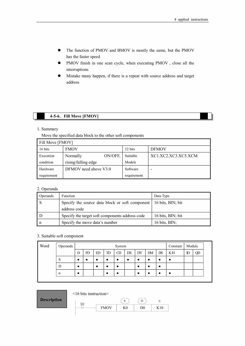
4-5-6.Fill Move [FMOV] 1. Summary
Move the specified data block to the other soft components Fill Move [FMOV] 16 bits FMOV 32 bits DFMOV Execution
condition
Normally ON/OFF, rising/falling edge
Suitable
Models
XC1.XC2.XC3.XC5.XCM
Hardware
requirement
DFMOV need above V3.0 Software
requirement
-
2. Operands
Operands Function Data Type
S Specify the source data block or soft component address code
16 bits, BIN; bit
D Specify the target soft components address code 16 bits, BIN; bit n Specify the move data’s number 16 bits, BIN;
3. Suitable soft component
<16 bits instruction>
FMOV K0 D0 K10X0
nS· D·
The function of PMOV and BMOV is mostly the same, but the PMOV has the faster speed
PMOV finish in one scan cycle, when executing PMOV , close all the interruptions
Mistake many happen, if there is a repeat with source address and target address
Word Operands System Constant Module
D FD ED TD CD DX DY DM DS K /H ID QD
S ● ● ● ● ● ● ● ● ● ●
D ● ● ● ● ● ● ●
n ● ● ● ● ● ● ●
Description
4 applied instructions
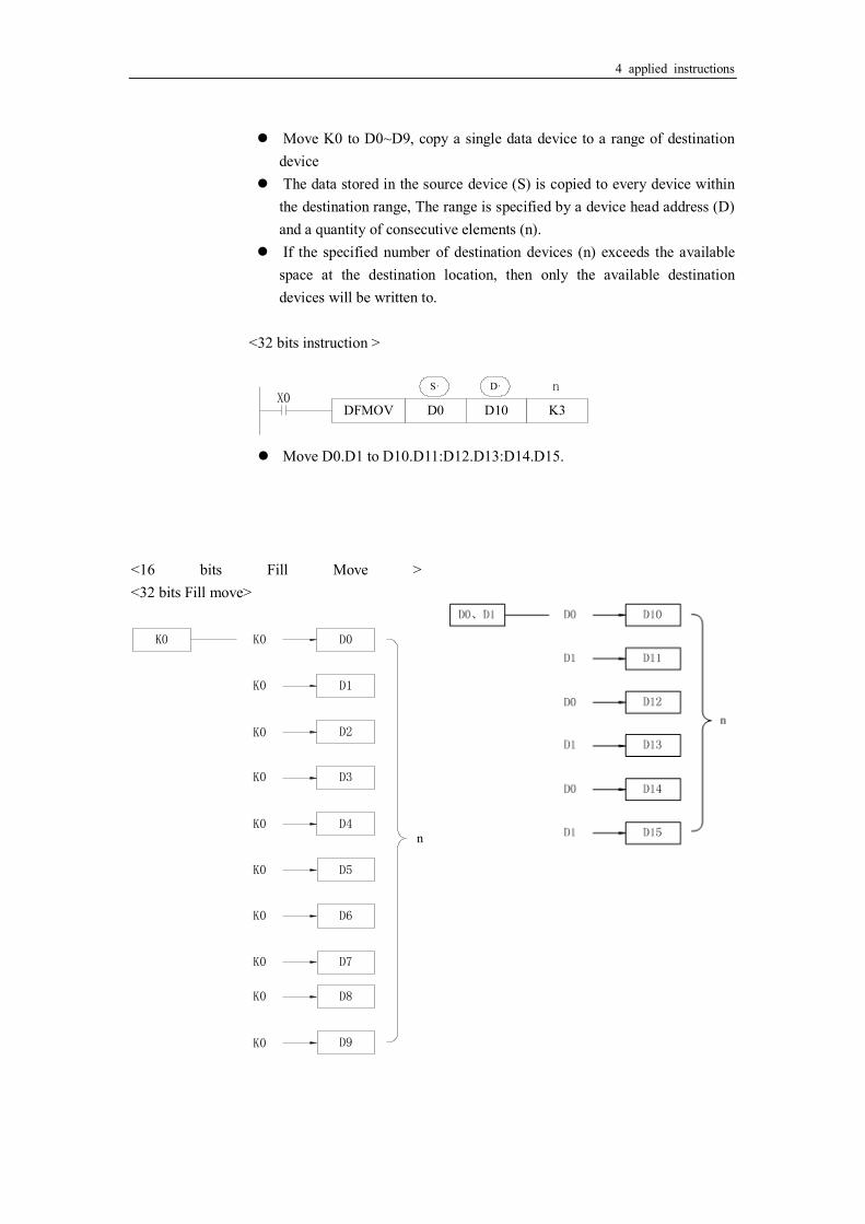
Move K0 to D0~D9, copy a single data device to a range of destination
device The data stored in the source device (S) is copied to every device within
the destination range, The range is specified by a device head address (D) and a quantity of consecutive elements (n).
If the specified number of destination devices (n) exceeds the available space at the destination location, then only the available destination devices will be written to.
<32 bits instruction >
DFMOV D0 D10 K3X0
nS· D·
Move D0.D1 to D10.D11:D12.D13:D14.D15.
<16 bits Fill Move > <32 bits Fill move>
K0 D0K0
n
D1K0
D2K0
D3K0
D4K0
D5K0
D6K0
D7K0
D8K0
D9K0

4 applied instructions

4 applied instructions
4-5-7.FlashROM Write [FWRT] 1. Summary
Write the specified data to other soft components FlashROM Write [FWRT] 16 bits FWRT 32 bits DFWRT Execution
condition
rising/falling edge Suitable
Models
XC1.XC2.XC3.XC5.XCM
Hardware
requirement
- Software
requirement
-
2. Operands
Operands Function Data Type
S The data write in the source or save in the soft element
16 bits/32 bits, BIN
D Write in target soft element 16 bits/32 bits, BIN D1 Write in target soft element start address 16 bits/32 bits, BIN D2 Write in data quantity bit
3. Suitable soft components
< Written of a word >
D0FWRT FD0X0
S· D·
<Written of double word> <Written of multi-word>
D0DFWRT FD0X1
S· D·
※1:FWRT instruction only allow to write data into FlashRom register. In this storage, even battery drop, data
could be used to store important technical parameters
※2:Written of FWRT needs a long time, about 150ms, so frequently operate this operate this operate operation is
Operands System Constant Module
D FD ED TD CD DX DY DM DS K /H ID QD
S ● ● ● ● ● ● ● ● ●
D ●
D1 ●
D2 ● ● ● ● ● ● ● ●
Word
Description
Write value in D0 into FD0
D0FWRT FD0X2
K3
S· D1· D2·
Write value in D0,D1 into FD0,FD1 Write value in D0,D1,D2 into FD0,FD1,FD2

4 applied instructions
recommended
※3:The written time of Flshrom is about 1,000,000 times. So we suggest using edge signal (LDP, LDF etc.) to
trigger.
※4:Frequently written of FlashROM
4-5-8.Zone set [MSET]
1. Summary Set or reset the soft element in certain range
Multi-set [MSET] 16 bits MSET.ZRST 32 bits - Execution
condition
Normally ON/OFF Suitable
Models
XC1.XC2.XC3.XC5.XCM
Hardware
requirement
- Software
requirement
-
2. Operands
Operands Function Data Type
D1 Start soft element address bit D2 End soft element address bit
3. Suitable soft components
MSET M10 M120
D1· D2·X0
Operands System
X Y M S T C Dn.m
D1 ● ● ● ● ● ●
D2 ● ● ● ● ● ●
Bit
Zone set unit M10~M120 Description
Are specified as the same type of soft units, and < When > ,will not run Zone set, set M8004.M8067,and
D8067=2。
D2·D1·D2·D1·
D2·D1·

4 applied instructions
4-5-9.Zone reset [ZRST] 1. Summary Reset the soft element in the certain range
Multi-reset [ZRST] 16 bits ZRST 32 bits - Execution
condition
Normally ON/OFF Suitable
Models
XC1.XC2.XC3.XC5.XCM
Hardware
requirement
- Software
requirement
-
2. Operands
Operands Function Data Type
D1 Start address of soft element Bit:16 bits,BIN D2 End address of soft element Bit:16 bits,BIN
3. Suitable soft components
ZRST M500 M559
D0 D100
D1· D2·
D1· D2·
X0
ZRST
Operands System Constant Module
D FD ED TD CD DX DY DM DS K /H ID QD
D1 ● ● ● ●
D2 ● ● ● ● ●
Word
Operands System
X Y M S T C Dn.m
D1 ● ● ● ● ● ●
D2 ● ● ● ● ● ●
Bit
Zone reset bits M5 00~M559。
Zone reset words D0~D100
Description
Are specified as the same type of soft units, and < When > , only reset the soft unit specified in ,and set
M8004.M8067,D8067=2。
D2·D1·D2·D1·
D1·D2·D1·
Other Reset Instruction
As soft unit’s separate reset instruction, RST instruction can be used to bit unit Y, M, S and word unit T, C, D
As fill move for constant K0, 0 can be written into DX, DY, DM, DS, T, C, D.
4 applied instructions
4-5-10.Swap the high and low byte [SWAP] 1. Summary
Swap the high and low byte High and low byte swap [SWAP] 16 bits SWAP 32 bits - Execution
condition
Normally ON/OFF Suitable
Models
XC1.XC2.XC3.XC5.XCM
Hardware
requirement
- Software
requirement
-
2. Operands
Operands Function Data Type
S The address of the soft element 16 bits: BIN 3. Suitable soft components
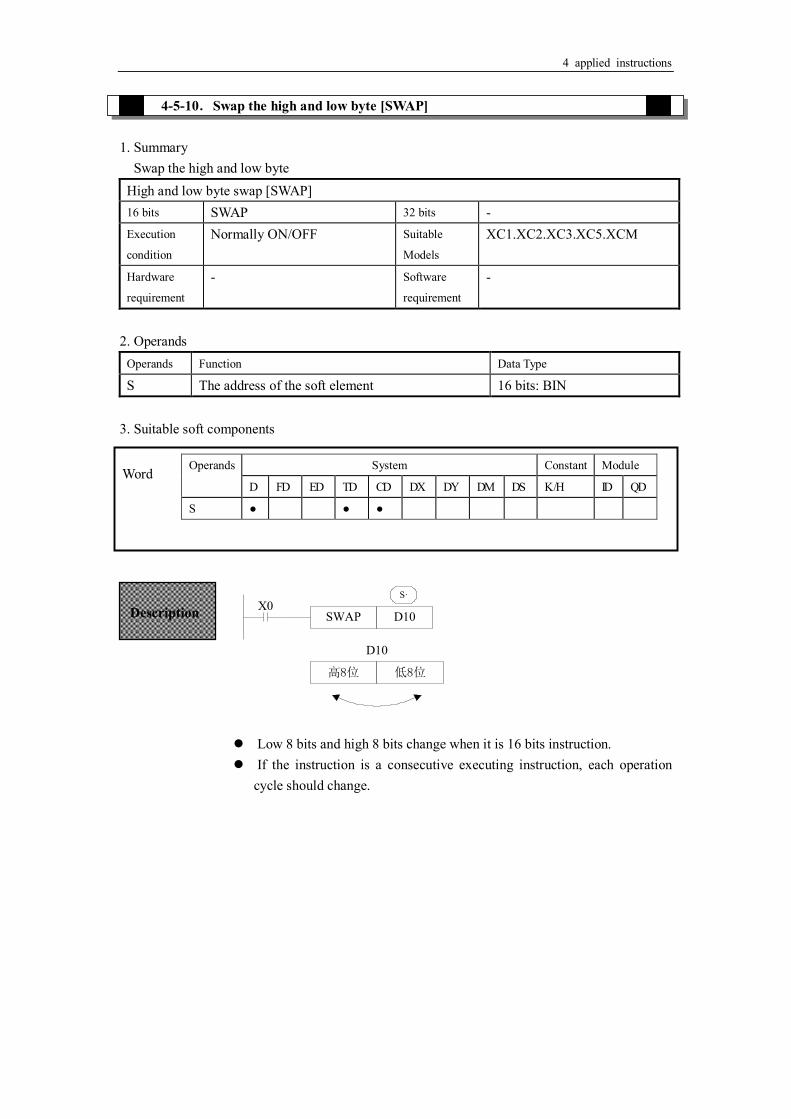
SWAP D10
高8位
D10
低8位
S·X0
Word Operands System Constant Module
D FD ED TD CD DX DY DM DS K /H ID QD
S ● ● ●
Description
Low 8 bits and high 8 bits change when it is 16 bits instruction. If the instruction is a consecutive executing instruction, each operation
cycle should change.

4 applied instructions
4-5-11.Exchange [XCH] 1. Summary
Exchange the data in two soft element Exchange [XCH] 16 bits XCH 32 bits DXCH Execution
condition
Normally ON/OFF Suitable
Models
XC1.XC2.XC3.XC5.XCM
Hardware
requirement
- Software
requirement
-
2. Operands
Operands Function Data Type
D1 The soft element address 16 bits, BIN D2 The soft element address 16 bits, BIN
3. Suitable soft component <16 bits instruction>
XCH D10 D11X0
D1· D2·
<32 bits instruction >
DXCH D10 D20X0
D1· D2·
Operands System Constant Module
D FD ED TD CD DX DY DM DS K /H ID QD
D1 ● ● ● ● ● ●
D2 ● ● ● ● ● ●
Word
Description
Before(D10)=100 →After (D10)=101
(D11)=101 (D11)=100
The contents of the two destination devices D1 and D2 are swapped, When drive input X0 is ON, each scan cycle should carry on data
exchange, please note.
32 bits instruction [DXCH] swaps value composed by D10、D11 and the value composed by D20、D21.

4 applied instructions
4-5-12.Floating move [EMOV]
1. Summary Send the floating number from one soft element to another
Floating move [EMOV] 16 bits - 32 bits EMOV Execution condition
Normally on/off, edge trigger Suitable models
XC2、XC3、XC5、XCM、XCC
Hardware V3.3 and higher Software V3.3 and higher
2. Operands Operand Function Type S Source soft element address 32 bits, BIN D Destination soft element address 32 bits, BIN
3. Suitable soft element
<32 bits instruction>
Binary floating → binary floating
(D1,D0)→(D11,D10)
X0 is ON, send the floating number from (D1, D0) to (D11, D10). X0 is OFF, the instruction doesn’t work
EMOV K500 D10X0
S· D·
(K500)→(D11,D10)
If constant value K, H is source soft element, they will be converted to floating number.
K500 will be converted to floating value.
Operand System Constant Module
D FD ED TD CD DX DY DM DS K /H ID QD
S ● ● ● ● ● ● ●
D ● ● ● ●
Word
Description
4 applied instructions
4-6.Data Operation Instructions
Mnemonic Function Chapter ADD Addition 4-6-1 SUB Subtraction 4-6-2 MUL Multiplication 4-6-3 DIV Division 4-6-4 INC Increment 4-6-5 DEC Decrement 4-6-5 MEAN Mean 4-6-6 WAND Logic Word And 4-6-7 WOR Logic Word Or 4-6-7 WXOR Logic Exclusive Or 4-6-7 CML Compliment 4-6-8 NEG Negation 4-6-9

4 applied instructions
4-6-1 Addition [ADD] 1. Summary
Add two numbers and store the result Add [ADD] 16 bits ADD 32 bits DADD Execution
condition
Normally ON/OFF Suitable
Models
XC1.XC2.XC3.XC5.XCM
Hardware
requirement
- Software
requirement
-
2. Operands
Operands Function Data Type
S1 The number address 16 bit/32 bit, BIN S2 The number address 16 bit/32bit, BIN D The result address 16 bit/32bit, BIN
3. Suitable soft components
ADD D10 D12 D14X0
S1· S2· D·
Operands System Constant Module
D FD ED TD CD DX DY DM DS K /H ID QD
S1 ● ● ● ● ● ● ● ● ●
S2 ● ● ● ● ● ● ● ● ●
D ● ● ● ● ● ●
Word
Description
(D10)+(D12)→(D14)
The data contained within the two source devices are combined and the total is stored in the specified destination device. Each data’s highest bit is the sign bit, 0 stands for positive、1 stands for negative. All calculations are algebraic processed.(5+(-8)=-3)
If the result of a calculation is “0”, the “0” flag acts. If the result exceeds 323,767(16 bits limit)or 2,147,483,647(32 bits limit), the carry flag acts.(refer to the next page). If the result exceeds –323,768(16 bits limit)or –2,147,483,648(32 bits limit), the borrow flag acts(Refer to the next page。
When carry on 32 bits operation, word device’s low 16 bits are assigned, the device following closely the preceding device’s ID will be the high bits. To avoid ID repetition, we recommend you assign device’s ID to be even ID.
The same device may be used as a source and a destination. If this is the case then the result changes after every scan cycle. Please note this point.

4 applied instructions
Flag meaning
Flag Name Function
M8020 Zero ON:the calculate result is zero OFF:the calculate result is not zero
M8021 Borrow ON:the calculate result is less than -32768(16 bit) or -2147483648(32bit) OFF:the calculate result is over -32768(16 bit) or -2147483648(32bit)
M8022 Carry ON:the calculate result is over 32768(16 bit) or 2147483648(32bit) OFF:the calculate result is less than 32768(16 bit) or 2147483648(32bit)
4-6-2.Subtraction [SUB] 1. Summary
Sub two numbers, store the result Subtraction [SUB] 16 bits SUB 32 bits DSUB Execution
condition
Normally ON/OFF Suitable
Models
XC1.XC2.XC3.XC5.XCM
Hardware
requirement
- Software
requirement
-
2.Operands
Operands Function Data Type
S1 The number address 16 bits /32 bits,BIN S2 The number address 16 bits /32 bits,BIN D The result address 16 bits /32 bits,BIN
3.Suitable soft component
Related flag
Operands System Constant Module
D FD ED TD CD DX DY DM DS K /H ID QD
S1 ● ● ● ● ● ● ● ● ●
S2 ● ● ● ● ● ● ● ● ●
D ● ● ● ● ● ●
Word

4 applied instructions
SUB D10 D12 D14
X0S1· S2· D·
The relationship of the flag’s action and vale’s positive/negative is shown below:
4-6-3.Multiplication [MUL]
1. Summary
Multiply two numbers, store the result Multiplication [MUL] 16 bits MUL 32 bits DMUL Execution
condition
Normally ON/OFF Suitable
Models
XC1.XC2.XC3.XC5.XCM
Hardware
requirement
- Software
requirement
-
2. Operands
Operands Function Data Type
S1 The number address 16 bits/32bits,BIN S2 The number address 16 bits/32bits,BIN D The result address 16 bits/32bits,BIN
3. Suitable soft component
(D10)—(D12)→(D14) Description
appoint the soft unit’s content, subtract the soft unit’s content appointed by in the format of algebra. The result will be stored in the soft unit appointed by . (5-(-8)=13)
The action of each flag, the appointment method of 32 bits operation’s soft units are both the same with the preceding ADD instruction.
The importance is: in the preceding program, if X0 is ON, SUB operation will be executed every scan cycle
S1· S2·
D·

4 applied instructions
<16 bits Operation>
MUL D0 D2 D4X0
S1· S2· D·
<32 bits Operation >
X1DMUL D0 D2 D4
S1· S2· D·
4-6-4.Division [DIV] 1. Summary
Divide two numbers and store the result Division [DIV] 16 bits DIV 32 bits DDIV Execution
condition
Normally ON/OFF, rising/falling edge
Suitable
Models
XC1.XC2.XC3.XC5.XCM
Hardware
requirement
- Software
requirement
-
2. Operands
Operands Function Data Type
S1 The number address 16 bits / 32 bits, BIN S2 The number address 16 bits /32 bits, BIN
Operands System Constant Module
D FD ED TD CD DX DY DM DS K /H ID QD
S1 ● ● ● ● ● ● ● ● ●
S2 ● ● ● ● ● ● ● ● ●
D ● ● ● ● ● ●
Word
Description BIN BIN BIN
(D0) × (D2) → (D5,D4)
16 bits 16 bits → 32 bits
The contents of the two source devices are multiplied together and the result is stored at the destination device in the format of 32 bits. As in the upward chart: when (D0)=8、(D2)=9, (D5, D4) =72.
The result’s highest bit is the symbol bit: positive (0)、negative (1). When be bit unit, it can carry on the bit appointment of K1~K8. When appoint K4, only
the result’s low 16 bits can be obtained.
BIN BIN BIN
(D1,D0)× (D3,D2) → (D7,D6,D5,D4)
32 bits 32 bits → 64 bits
When use 2 bits Operation ,the result is stored at the destination device in the format of 64 bits.
Even use word device, 64 bits results can’t be monitored at once.

4 applied instructions
D The result address 16 bits /32 bits, BIN 3.Suitable soft components
<16 bits operation >
DIV D0 D2 D4X0
S1· S2· D·
<32 bits operation >
DDIV D0 D2 D4X1
S1· S2· D·
Operands System Constant Module
D FD ED TD CD DX DY DM DS K /H ID QD
S1 ● ● ● ● ● ● ● ● ●
S2 ● ● ● ● ● ● ● ● ●
D ● ● ● ● ● ●
Word
Dividend Divisor Result Remainder
BIN BIN BIN BIN
(D0) ÷ (D2) → D4) ┅ (D5)
16 bits 16 bits 16 bits 16 bits
Description
appoints the device’s content be the dividend, appoints the device’s content be the divisor, appoints the device and the next one to store the result and the remainder.
In the above example, if input X0 is ON, devision operation is executed every scan cycle.
D·
S2·S1·
Dividend Divisor Result Remainder
BIN BIN BIN BIN
(D1,D0) ÷ (D3,D2) (D5,D4)┅ (D7,D6)
32 bits 32 bits 32 bits 32 bits
The dividend is composed by the device appointed by and the next one. The divisor is composed by the device appointed by and the next one. The result and the remainder are stored in the four sequential devices, the first one is appointed by
If the value of the divisor is 0, then an operation error is executed and the operation of the DIV instruction is cancelled
S1·
S2·
D·
The highest bit of the result and remainder is the symbol bit (positive:0, negative: 1). When any of the dividend or the divisor is negative, then the result will be negative. When the dividend is negative, then the remainder will be negative.

4 applied instructions
4-6-5.Increment [INC] & Decrement [DEC] 1. Summary
Increase or decrease the number Increment 1[INC] 16 bits INC 32 bits DINC Execution
condition
Normally ON/OFF, rising/falling edge
Suitable
Models
XC1.XC2.XC3.XC5.XCM
Hardware
requirement
- Software
requirement
-
Increment 1[DEC] 16 bits DEC 32 bits DDEC Execution
condition
Normally ON/OFF, rising/falling edge
Suitable
Models
XC1.XC2.XC3.XC5.XCM
Hardware
requirement
- Software
requirement
-
2. Operands
Operands Function Data Type
D The number address 16 bits / 32bits,BIN 3. Suitable soft components
< Increment [INC]>
INC D0X0
D·
<Decrement [DEC]>
Word Operands System Constant Module
D FD ED TD CD DX DY DM DS K /H ID QD
D ● ● ● ● ● ●
Description
(D0)+1→(D0)
On every execution of the instruction the device specified as the destination has its current value incremented (increased) by a value of 1.
In 16 bits operation, when +32,767 is reached, the next increment will write -32,767 to the destination device. In this case, there’s no additional flag to identify this change in the counted value.
D·

4 applied instructions
DEC D0X1
D·
4-6-6.Mean [MEAN] 1. Summary
Get the mean value of numbers Mean [MEAN] 16 bits MEAN 32 bits DMEAN Execution
condition
Normally ON/OFF, rising/falling edge
Suitable
Models
XC1.XC2.XC3.XC5.XCM
Hardware
requirement
- Software
requirement
-
2. Operands
Operands Function Data Type
S The head address of the numbers 16 bits, BIN D The mean result address 16 bits, BIN n The number quantity 16 bits, BIN
3. Suitable soft components
(D0) + +
3(D10)
(D1) (D2)
(D0)-1 →(D0)
On every execution of the instruction the device specified as the destination has its current value decremented (decreased) by a value of 1.
When -32,768 or -2,147,483,648 is reached, the next decrement will write +32,767 or +2,147,483,647 to the destination device.
D·
Operands System Constant Module
D FD ED TD CD DX DY DM DS K /H ID QD
S ● ● ● ● ● ● ●
D ● ● ● ● ● ●
n ●
Word
Description MEAN D0 D10 K3
S· D·X0
n
4 applied instructions
4-6-7.Logic AND [WAND] , Logic OR[WOR], Logic Exclusive OR [WXOR] 1. Summary
Do logic AND, OR, XOR for numbers Logic AND [WAND] 16 bits WAND 32 bits DWAND Execution
condition
Normally ON/OFF, rising/falling edge
Suitable
Models
XC1.XC2.XC3.XC5.XCM
Hardware
requirement
- Software
requirement
-
Logic OR[WOR] 16 bits WOR 32 bits DWOR Execution
condition
Normally ON/OFF, rising/falling edge
Suitable
Models
XC1.XC2.XC3.XC5.XCM
Hardware
requirement
- Software
requirement
-
Logic Exclusive OR [WXOR] 16 bits WXOR 32 bits DWXOR Execution
condition
Normally ON/OFF, rising/falling edge
Suitable
Models
XC1.XC2.XC3.XC5.XCM
Hardware
requirement
- Software
requirement
-
2. Operands
Operands Function Data Type
S1 The soft element address 16bit/32bit,BIN S2 The soft element address 16bit/32bit,BIN D The result address 16bit/32bit,BIN
The value of all the devices within the source range is summed and then divided by the number of devices summed, i.e. n.. This generates an integer mean value which is stored in the destination device (D) The remainder of the calculated mean is ignored.
If the value of n is specified outside the stated range (1 to 64) an error is generated.

4 applied instructions
3. Suitable soft components
< Execute logic AND operation with each bit>
WAND D10 D12 D14
D·X0
S1· S2·
< Execute logic OR operation with each bit >
WOR D10 D12 D14
D·X0
S1· S2·
< Execute logic Exclusive OR operation with each bit >
WXOR D10 D12 D14
D·X0
S1· S2·
If use this instruction along with CML instruction, XOR NOT operation could also be executed.
WXOR D10 D12 D14
D·X0
S1· S2·
CML D14 D14
Operands System Constant Module
D FD ED TD CD DX DY DM DS K /H ID QD
S1 ● ● ● ● ● ● ● ●
S2 ● ● ● ● ● ● ● ●
D ● ● ● ● ● ●
Word
Description 0&0=0 0&1=0 1&0=0 1&1=1
0 or 0=0 0 or 1=1 1 or 0=1 1 or 1=1
0 xor 0=0 0 xor 1=1 1 xor 0=1 1 xor 1=0

4 applied instructions
4-6-8.Converse [CML] 1. Summary
Converse the phase of the numbers Converse [CML] 16 bits CML 32 bits DCML Execution
condition
Normally ON/OFF, rising/falling edge
Suitable
Models
XC1.XC2.XC3.XC5.XCM
Hardware
requirement
- Software
requirement
-
2. Operands
Operands Function Data Type
S Source number address 16 bits/32 bits, BIN D Result address 16 bits/32 bits, BIN
3. Suitable soft components
CML D0 DY0
S· D·M0↑
0 1 0 1 0 1 0 1 0 1 0 1 0 1 0 1
1 0 1 0 1 0 1 0 1 0 1 0 1 0 1 0
D0
Y17 Y7 Y6 Y5 Y4
Sign bit
(0=positive,1=negative)
< Reading of inverted input >
Word Operands System Constant Module
D FD ED TD CD DX DY DM DS K /H ID QD
S1 ● ● ● ● ● ● ● ● ●
D ● ● ● ● ● ●
Each data bit in the source device is inverted (1→0,0→1) and sent to the destination device. If use constant K in the source device, it can be auto convert to be binary.
It’s available when you want to inverted output the PLC’s output
Description

4 applied instructions
M0
M1
M2
M3
M17
CML DX0 DM0M8000
X0
X1
X2
X3
X17
4-6-9.Negative [NEG]
1. Summary
Get the negative number Negative [NEG] 16 bits NEG 32 bits DNEG Execution
condition
Normally ON/OFF, rising/falling edge
Suitable
Models
XC1.XC2.XC3.XC5.XCM
Hardware
requirement
- Software
requirement
-
2. Operands
Operands Function Data Type
D The source number address 16 bits/ bits, BIN 3. Suitable soft components
NEG D10 (D10) +1 (D10)M0
D·
The sequential control instruction in the left could be denoted by the following CML instruction.
Operands System Constant Module
D FD ED TD CD DX DY DM DS K /H ID QD
D ● ● ● ● ● ●
Word
Description
The bit format of the selected device is inverted, I.e. any occurrence of a “1’ becomes a “0” and any occurrence of “0” becomes “1”, when this is complete, a further binary 1 is added to the bit format. The result is the total logic sigh change of the selected devices contents.
4 applied instructions
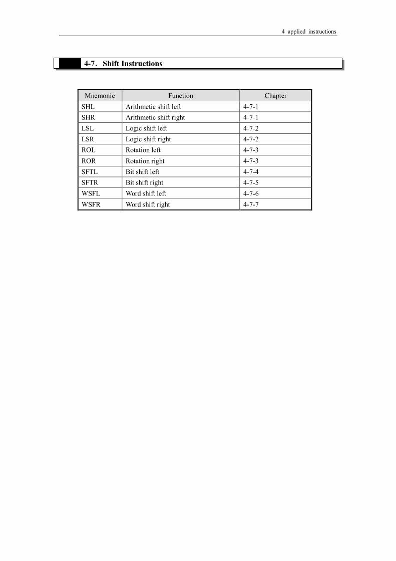
4-7.Shift Instructions
Mnemonic Function Chapter SHL Arithmetic shift left 4-7-1 SHR Arithmetic shift right 4-7-1 LSL Logic shift left 4-7-2 LSR Logic shift right 4-7-2 ROL Rotation left 4-7-3 ROR Rotation right 4-7-3 SFTL Bit shift left 4-7-4 SFTR Bit shift right 4-7-5 WSFL Word shift left 4-7-6 WSFR Word shift right 4-7-7

4 applied instructions
4-7-1.Arithmetic shift left [SHL], Arithmetic shift right [SHR] 1. Summary
Do arithmetic shift left/right for the numbers Arithmetic shift left [SHL] 16 bits SHL 32 bits DSHL Execution
condition
Normally ON/OFF, rising/falling edge
Suitable
Models
XC2.XC3.XC5.XCM
Hardware
requirement
- Software
requirement
-
Arithmetic shift right [SHR] 16 bits SHR 32 bits DSHR Execution
condition
Normally ON/OFF, rising/falling edge
Suitable
Models
XC2.XC3.XC5.XCM
Hardware
requirement
- Software
requirement
-
2. Operands
Operands Function Data Type
D The source data address 16bit/32bit,BIN n Shift left or right times 16bit/32bit,BIN
3. Suitable soft components
< Arithmetic shift left > < Arithmetic shift right >
Operands System Constant Module
D FD ED TD CD DX DY DM DS K /H ID QD
D ● ● ● ● ● ●
n ●
Word
After once execution, the low bit is filled in 0, the final bit is stored in carry flag.
After once execution, the high bit is same with the bit before shifting, the final bit is stored in carry flag.
Description
4 applied instructions
、
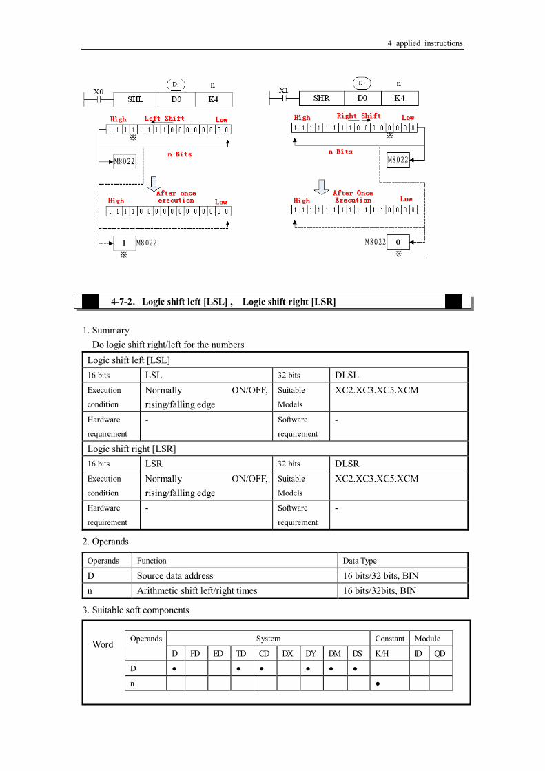
4-7-2.Logic shift left [LSL] , Logic shift right [LSR] 1. Summary
Do logic shift right/left for the numbers Logic shift left [LSL] 16 bits LSL 32 bits DLSL Execution
condition
Normally ON/OFF, rising/falling edge
Suitable
Models
XC2.XC3.XC5.XCM
Hardware
requirement
- Software
requirement
-
Logic shift right [LSR] 16 bits LSR 32 bits DLSR Execution
condition
Normally ON/OFF, rising/falling edge
Suitable
Models
XC2.XC3.XC5.XCM
Hardware
requirement
- Software
requirement
-
2. Operands
Operands Function Data Type
D Source data address 16 bits/32 bits, BIN n Arithmetic shift left/right times 16 bits/32bits, BIN
3. Suitable soft components
Operands System Constant Module
D FD ED TD CD DX DY DM DS K /H ID QD
D ● ● ● ● ● ●
n ●
Word

4 applied instructions
LSR and SHR is different, LSR add 0 in high bit when moving, SHR all bits are moved.
< Logic shift left > < Logic shift right >
4-7-3.Rotation shift left [ROL] , Rotation shift right [ROR] 1. Summary
Continue and cycle shift left or right Rotation shift left [ROL] 16 bits ROL 32 bits DROL Execution
condition
Normally ON/OFF, rising/falling edge
Suitable
Models
XC2.XC3.XC5.XCM
Hardware
requirement
- Software
requirement
-
Rotation shift right [ROR] 16 bits ROR 32 bits DROR Execution
condition
Normally ON/OFF, rising/falling edge
Suitable
Models
XC2.XC3.XC5.XCM
Hardware
requirement
- Software
requirement
-
2. Operands Operands Function Data Type
After once execution, the low bit is filled in 0, the final bit is stored in carry flag.
LSL meaning and operation are the same as SHL. After once execution, the high bit is same with the bit before shifting,
the final bit is stored in carry flag。
Description

4 applied instructions
D Source data address 16 bits/32 bits, BIN n Shift right or left times 16 bits/32 bits, BIN
3. Suitable soft components
< Rotation shift left > < Rotation shift right >
4-7-4.Bit shift left [SFTL]
1. Summary
Bit shift left Bit shift left [SFTL] 16 bits SFTL 32 bits DSFTL Execution
condition
Normally ON/OFF, rising/falling edge
Suitable
Models
XC2.XC3.XC5.XCM
Hardware
requirement
- Software
requirement
-
2. Operands
Operands Function Types S Source soft element head address bit D Target soft element head address bit
Operands System Constant Module
D FD ED TD CD DX DY DM DS K /H ID QD
D ● ● ● ● ● ●
n ●
Word
The bit format of the destination device is rotated n bit places to the left on every operation of the instruction.
Description
4 applied instructions
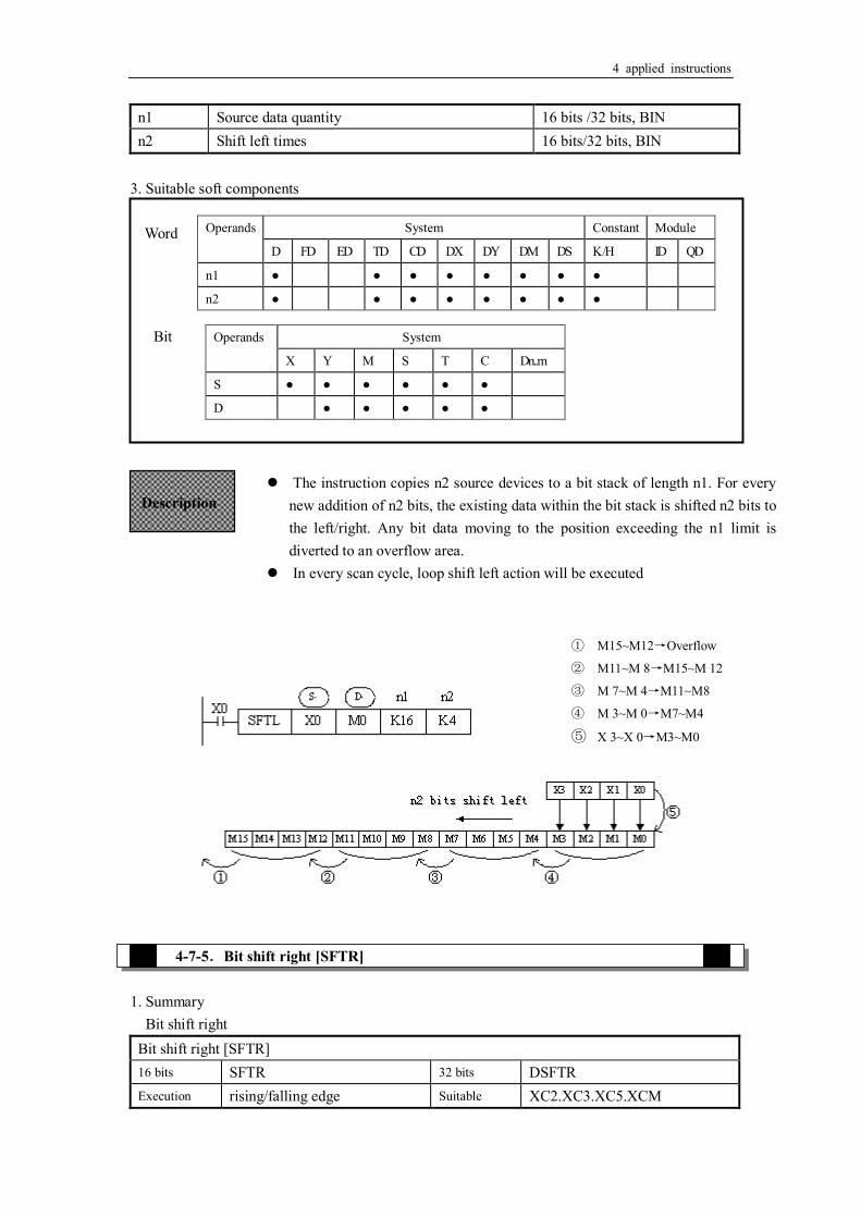
n1 Source data quantity 16 bits /32 bits, BIN n2 Shift left times 16 bits/32 bits, BIN
3. Suitable soft components
4-7-5.Bit shift right [SFTR] 1. Summary
Bit shift right Bit shift right [SFTR] 16 bits SFTR 32 bits DSFTR Execution rising/falling edge Suitable XC2.XC3.XC5.XCM
Word Operands System Constant Module
D FD ED TD CD DX DY DM DS K /H ID QD
n1 ● ● ● ● ● ● ● ●
n2 ● ● ● ● ● ● ● ●
Operands System
X Y M S T C Dn..m
S ● ● ● ● ● ●
D ● ● ● ● ●
Bit
The instruction copies n2 source devices to a bit stack of length n1. For every new addition of n2 bits, the existing data within the bit stack is shifted n2 bits to the left/right. Any bit data moving to the position exceeding the n1 limit is diverted to an overflow area.
In every scan cycle, loop shift left action will be executed
Description
① M15~M12→Overflow
② M11~M 8→M15~M 12
③ M 7~M 4→M11~M8
④ M 3~M 0→M7~M4
⑤ X 3~X 0→M3~M0

4 applied instructions
condition Models
Hardware
requirement
- Software
requirement
-
2. Operands
Operands Function Data Type
S Source soft element head address bit D Target soft element head address bit n1 Source data quantity 16 bits/32 bits, BIN n2 Shift right times 16 bits/32 bits, BIN
3. Suitable soft components
Operands System Constant Module
D FD ED TD CD DX DY DM DS K /H ID QD
n1 ● ● ● ● ● ● ● ●
n2 ● ● ● ● ● ● ● ●
Word
Bit
The instruction copies n2 source devices to a bit stack of length n1. For every new addition of n2 bits, the existing data within the bit stack is shifted n2 bits to the left/right. Any bit data moving to the position exceeding the n1 limit is diverted to an overflow area.
In every scan cycle, loop shift right action will be executed
Description
① M 3~M 0→Overflow
② M 7~M 4→M3~M0
③ M11~M 8→M7~M4
④ M15~M12→M11~M8
⑤ X 3~X 0→M15~M12
Operands System
X Y M S T C Dn..m
S ● ● ● ● ● ●
D ● ● ● ● ●

4 applied instructions
n2 word shift left
4-7-6.Word shift left [WSFL]
1. Summary
Word shift left Word shift left [ [WSFL] 16 bits WSFL 32 bits - Execution
condition
rising/falling edge Suitable
Models
XC2.XC3.XC5.XCM
Hardware
requirement
- Software
requirement
-
2. Operands
Operands Function Data Type
S Source soft element head address 16 bits/32 bits, BIN D Target soft element head address 16 bits /32 bits, BIN n1 Source data quantity 16 bits /32 bits, BIN n2 Word shift left times 16 bits /32 bits, BIN
3. Suitable soft components
Operands System Constant Module
D FD ED TD CD DX DY DM DS K /H ID QD
S ● ● ● ● ● ● ● ●
D ● ● ● ● ● ●
n1 ● ● ● ● ● ● ●
n2 ● ● ● ● ● ● ●
Word
Description The instruction copies n2 source devices to a word stack of length n1. For each addition of n2 words, the existing data within the word stack is shifted n2 words to the left. Any word data moving to a position exceeding the n1 limit is diverted to an overflow area.
In every scan cycle, loop shift left action will be executed.
① D25~D22→Overflow
② D21~D18→D25~D22
③ D17~D14→D21~D18
④ D13~D10→D17~D14
⑤ D 3~D 0→D13~D10

4 applied instructions
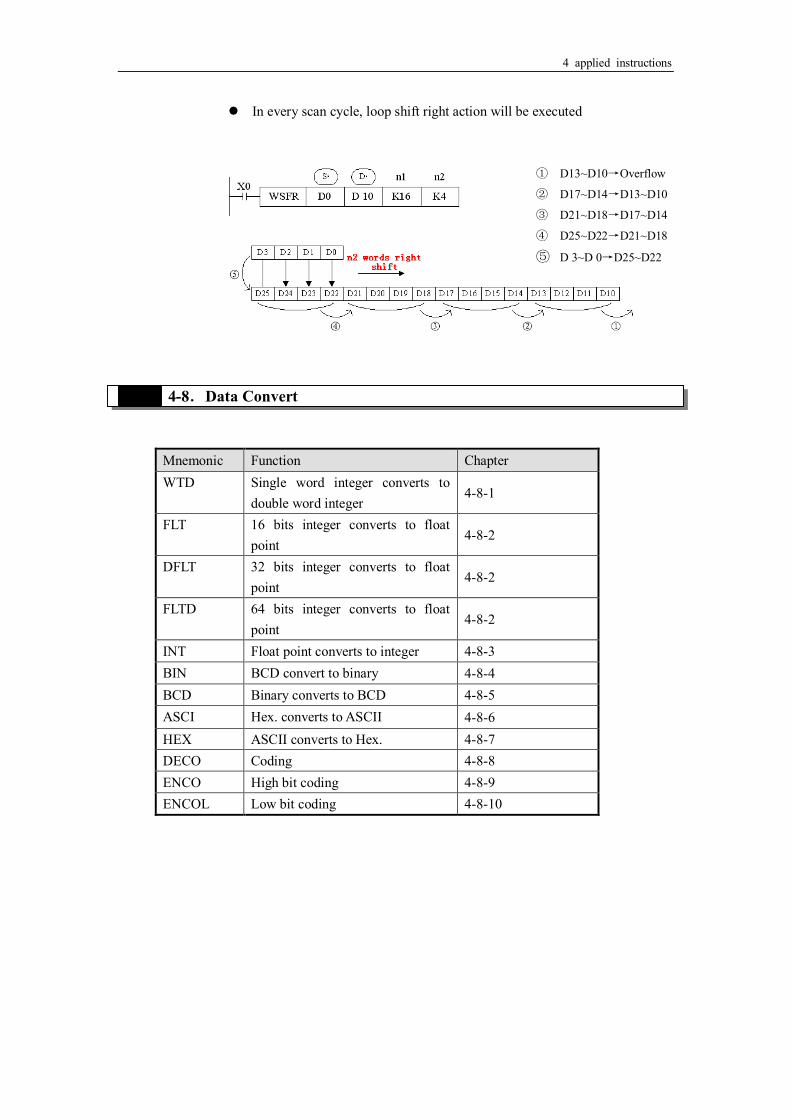
4-7-7.Word shift right[WSFR] 1. Summary
Word shift right Word shift right [WSFR] 16 bits WSFR 32 bits - Execution
condition
rising/falling edge Suitable
Models
XC2.XC3.XC5.XCM
Hardware
requirement
- Software
requirement
-
2. Operands
Operands Function Data Type
S Source soft element head address 16 bits/32 bits, BIN D Target soft element head address 16 bits/32 bits, BIN n1 Source data quantity 16 bits/32 bits, BIN n2 Shift right times 16 bits/32 bits, BIN
3. Suitable soft components
Operands System Constant Module
D FD ED TD CD DX DY DM DS K /H ID QD
S ● ● ● ● ● ● ● ●
D ● ● ● ● ● ●
n1 ● ● ● ● ● ● ●
n2 ● ● ● ● ● ● ●
Word
Description The instruction copies n2 source devices to a word stack of length n1.
For each addition of n2 words, the existing data within the word stack is shifted n2 words to the right. Any word data moving to a position exceeding the n1 limit is diverted to an overflow area.
4 applied instructions
n2 字右移
4-8.Data Convert
Mnemonic Function Chapter WTD Single word integer converts to
double word integer 4-8-1
FLT 16 bits integer converts to float point
4-8-2
DFLT 32 bits integer converts to float point
4-8-2
FLTD 64 bits integer converts to float point
4-8-2
INT Float point converts to integer 4-8-3 BIN BCD convert to binary 4-8-4 BCD Binary converts to BCD 4-8-5 ASCI Hex. converts to ASCII 4-8-6 HEX ASCII converts to Hex. 4-8-7 DECO Coding 4-8-8 ENCO High bit coding 4-8-9 ENCOL Low bit coding 4-8-10
① D13~D10→Overflow
② D17~D14→D13~D10
③ D21~D18→D17~D14
④ D25~D22→D21~D18
⑤ D 3~D 0→D25~D22
In every scan cycle, loop shift right action will be executed

4 applied instructions
4-8-1.Single word integer converts to double word integer [WTD] 1. Summary
Single word integer converts to double word integer [WTD] 16 bits WTD 32 bits - Execution
condition
Normally ON/OFF, rising/falling edge
Suitable
Models
XC2.XC3.XC5.XCM
Hardware
requirement
- Software
requirement
-
2. Operands
Operands Function Data Type
S Source soft element address 16 bits, BIN D Target soft element address 32 bits, BIN
3.Suitable soft components
WTD D0 D10X0
S· D·
High bits Low bits
D11 D10
0 or 1 D0
Operands System Constant Module
D FD ED TD CD DX DY DM DS K /H ID QD
S ● ● ● ● ● ● ● ●
D ● ● ● ● ● ●
Word
Description (D0) → (D11,D10) Single Word Double
When single word D0 is positive integer, after executing this instruction, the high bit of double word D10 is 0.
When single word D0 is negative integer, after executing this instruction, the high bit of double word D10 is 1.
4 applied instructions
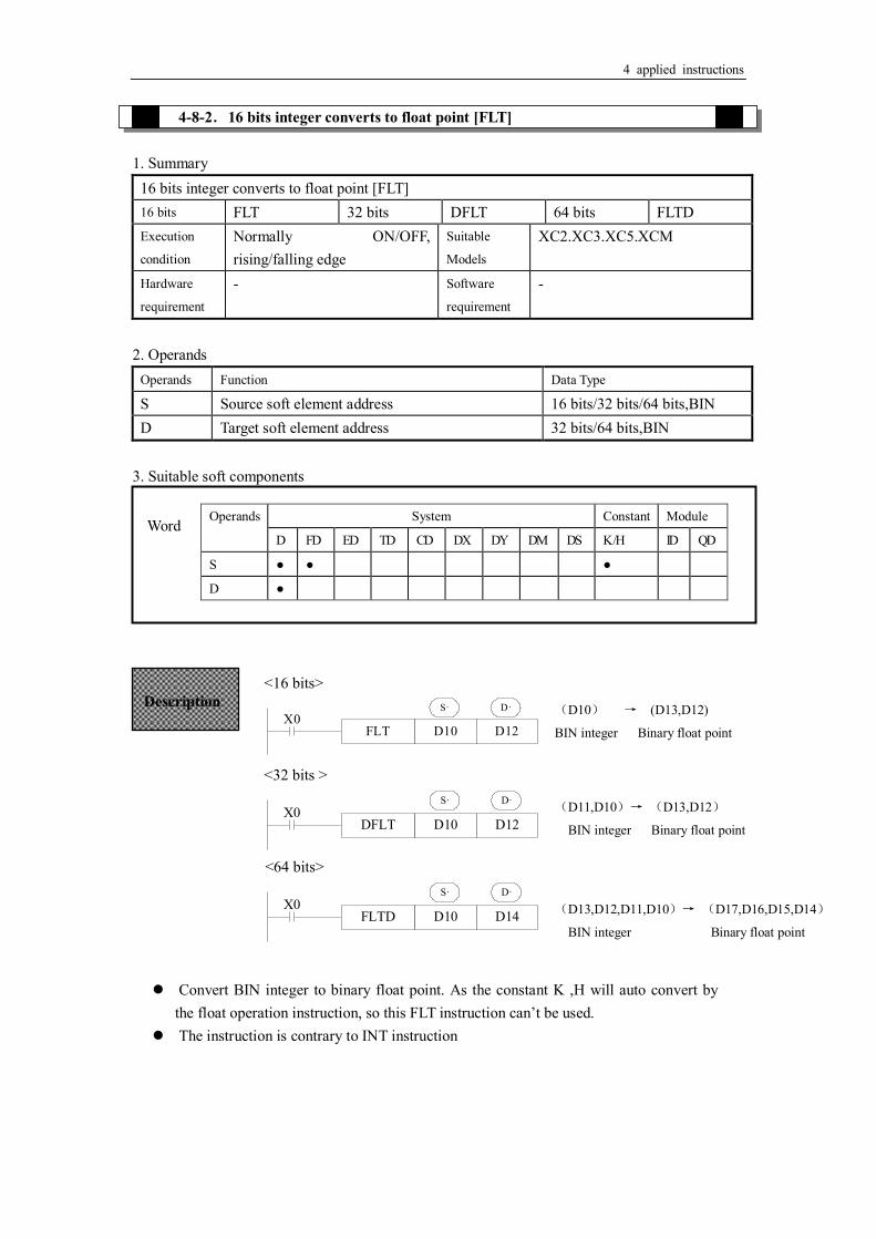
4-8-2.16 bits integer converts to float point [FLT] 1. Summary
16 bits integer converts to float point [FLT] 16 bits FLT 32 bits DFLT 64 bits FLTD Execution
condition
Normally ON/OFF, rising/falling edge
Suitable
Models XC2.XC3.XC5.XCM
Hardware
requirement
- Software
requirement -
2. Operands
Operands Function Data Type
S Source soft element address 16 bits/32 bits/64 bits,BIN D Target soft element address 32 bits/64 bits,BIN
3. Suitable soft components <16 bits>
<32 bits >
DFLT D10 D12
S· D·X0
<64 bits>
FLTD D10 D14
S· D·X0
Operands System Constant Module
D FD ED TD CD DX DY DM DS K /H ID QD
S ● ● ●
D ●
Word
Description (D10) → (D13,D12)
BIN integer Binary float point FLT D10 D12
S· D·X0
(D11,D10)→ (D13,D12)
BIN integer Binary float point
(D13,D12,D11,D10)→ (D17,D16,D15,D14)
BIN integer Binary float point
Convert BIN integer to binary float point. As the constant K ,H will auto convert by the float operation instruction, so this FLT instruction can’t be used.
The instruction is contrary to INT instruction
4 applied instructions
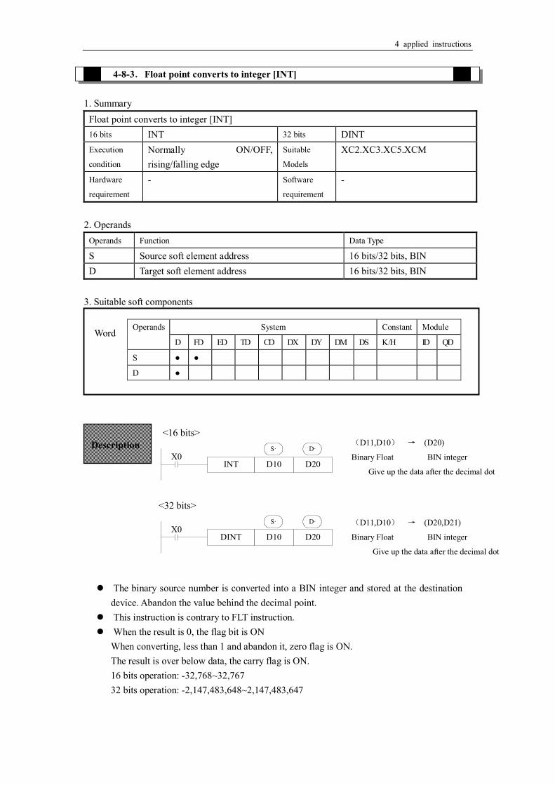
4-8-3.Float point converts to integer [INT] 1. Summary
Float point converts to integer [INT] 16 bits INT 32 bits DINT Execution
condition
Normally ON/OFF, rising/falling edge
Suitable
Models
XC2.XC3.XC5.XCM
Hardware
requirement
- Software
requirement
-
2. Operands
Operands Function Data Type
S Source soft element address 16 bits/32 bits, BIN D Target soft element address 16 bits/32 bits, BIN
3. Suitable soft components <16 bits>
INT D10 D20
S· D·X0
<32 bits>
DINT D10 D20
S· D·X0
Operands System Constant Module
D FD ED TD CD DX DY DM DS K /H ID QD
S ● ●
D ●
Word
Description (D11,D10) → (D20)
Binary Float BIN integer
Give up the data after the decimal dot
(D11,D10) → (D20,D21)
Binary Float BIN integer
Give up the data after the decimal dot
The binary source number is converted into a BIN integer and stored at the destination device. Abandon the value behind the decimal point.
This instruction is contrary to FLT instruction. When the result is 0, the flag bit is ON
When converting, less than 1 and abandon it, zero flag is ON. The result is over below data, the carry flag is ON. 16 bits operation: -32,768~32,767 32 bits operation: -2,147,483,648~2,147,483,647

4 applied instructions
4-8-4.BCD convert to binary [BIN] 1. Summary
BCD convert to binary [BIN] 16 bits BIN 32 bits - Execution
condition
Normally ON/OFF, rising/falling edge
Suitable
Models
XC2.XC3.XC5.XCM
Hardware
requirement
- Software
requirement
-
2. Operands
Operands Function Data Type
S Source soft element address BCD D Target soft element address 16 bits/32 bits, BIN
3. Suitable soft components
BIN D10 D0
S· D·X0
Operands System Constant Module
D FD ED TD CD DX DY DM DS K /H ID QD
S ● ● ● ● ● ● ● ●
D ● ● ● ● ● ●
Word
Description Convert and move instruction of Source (BCD) → destination (BIN)
When source data is not BCD code, M8067(Operation error), M8004 (error occurs) As constant K automatically converts to binary, so it’s not suitable for this instruction.

4 applied instructions
4-8-5.Binary convert to BCD [BCD] 1. Summary
Binary convert to BCD [BCD] 16 bits BCD 32 bits - Execution
condition
Normally ON/OFF, rising/falling edge
Suitable
Models
XC2.XC3.XC5.XCM
Hardware
requirement
- Software
requirement
-
2. Operands
Operands Function Data Type
S Source soft element address 16 bits/32 bits, BIN D Target soft element address BCD code
3. Suitable soft components
BCD D10 D0
S· D·X0
Operands System Constant Module
D FD ED TD CD DX DY DM DS K /H ID QD
S ● ● ● ● ● ● ● ●
D ● ● ● ● ● ●
Word
Description Convert and move instruction of source (BIN)→destination (BCD)
This instruction can be used to output data directly to a seven-segment display.

4 applied instructions
4-8-6.Hex. converts to ASCII [ASCI] 1. Summary
Hex. convert to ASCII [ASCI] 16 bits ASCI 32 bits - Execution
condition
Normally ON/OFF, rising/falling edge
Suitable
Models
XC2.XC3.XC5.XCM
Hardware
requirement
- Software
requirement
-
2. Operands
Operands Function Data Type
S Source soft element address 2 bits, HEX D Target soft element address ASCII code n Transform character quantity 16 bits, BIN
3. Suitable soft components
ASCI D100 D200 K4
S· D· nX0
The convert result is this
n D
K1 K2 K3 K4 K5 K6 K7 K8 K9
D200 down [C] [B] [A] [0] [4] [3] [2] [1] [8] D200 up [C] [B] [A] [0] [4] [3] [2] [1] D201 down [C] [B] [A] [0] [4] [3] [2] D201 up [C] [B] [A] [0] [4] [3] D202 down [C] [B] [A] [0] [4] D202 up [C] [B] [A] [0] D203 down [C] [B] [A]
Operands System Constant Module
D FD ED TD CD DX DY DM DS K /H ID QD
S ● ● ● ● ● ● ● ●
D ● ● ● ● ● ●
n ● ● ● ● ● ● ●
Word
Description
D·S· Convert each bit of source’s (S) Hex. format data to be ASCII code, move separately to the high 8 bits and low 8 bits of destination (D). The convert alphanumeric number is assigned with n.
is low 8 bits, high 8 bits, store ASCII data. D·

4 applied instructions
4-8-7.ASCII convert to Hex.[HEX]
1. Summary
ASCII converts to Hex. [HEX] 16 bits HEX 32 bits - Execution
condition
Normally ON/OFF, rising/falling edge
Suitable
Models
XC2.XC3.XC5.XCM
Hardware
requirement
- Software
requirement
-
2. Operands
Operands
Function Date type
S Source soft element address ASCII D Target soft element address 2 bits, HEX n Character quantity 16 bits, BIN
3. Suitable soft components
HEX D200 D100 K4
S· D· nX0
D203 up [C] [B] D204 down [C]
Assign start device: (D100)=0ABCH (D101)=1234H (D102)=5678H
[0]=30H [1]=31H [5]=35H [A]=41H [2]=32H [6]=36H [B]=42H [3]=33H [7]=37H [C]=43H [4]=34H [8]=38H
Operands System Constant Module
D FD ED TD CD DX DY DM DS K /H ID QD
S ● ● ● ● ● ● ● ●
D ● ● ● ● ● ●
n ●
Word
Description
Convert the high and low 8 bits in source to HEX data. Move 4 bits every time to destination . The convert alphanumeric number is assigned by n.
S·
D·

4 applied instructions
The convert of the upward program is the following: 时
n=k4 0 1 0 0 0 0 0 1 0 0 1 1 0 0 0 0D200
41H? [A] 30H? [0]
0 1 0 0 0 0 1 1 0 1 0 1 0 0 1 0D201
43H? [C] 42H? [B]
0 0 0 0 1 0 1 0 1 0 1 1 1 1 0 0D100
0 A B C
4-8-8.Coding [DECO] 1. Summary Transform the ASCII code to Hex numbers.
Coding [DECO] 16 bits DECO s - Execution
condition
Normally ON/OFF, rising/falling edge
Suitable
Models
XC2.XC3.XC5.XCM
Hardware
requirement
- Software
requirement
-
2. Operands
Operands Function Data Type
S Source soft element address ASCII D Target soft element address 2 bits HEX n The coding soft element quantity 16bits, BIN
2. Suitable soft components
(S·)
ASCII Code
HEX Convert
D200 down 30H 0 D200 up 41H A D201 down 42H B D201 up 43H C D202 down 31H 1 D202 up 32H 2 D203 down 33H 3 D203 up 34H 4 D204 down 35H 5
n (D·) D102 D101 D100
1 Not change to
be 0
···0H 2 ··0AH 3 ·0ABH 4 0ABCH 5 ···0H ABC1H 6 ··0AH BC12H 7 ·0ABH C123H 8 0ABCH 1234H 9 ···0H ABC1H 2345H

4 applied instructions
③
② ①
全部转化为 0 ③
① ②
< When is bit unit > n≤16
DX0DECO M10 K3X10
nS· D·
0 1 1
0 0 0 1 0 0 0
X002 X001 X000
M17 M16 M15 M14 M13 M12 M11 M10
7 6 5 4 2 1 0
4
0
< When is word device > n≤4
D0DECO D1 K3X0
nS· D·
Operands System Constant Module
D FD ED TD CD DX DY DM DS K /H ID QD
S ● ● ● ● ● ● ● ●
n ●
Word
Operands System
X Y M S T C Dn.m
D ● ● ● ● ● ●
Bit
Description D·
The source address is 1+2=3,so starts from M10, the number 3 bit (M13) is 1. If the source are all 0, M10 is 1.
When n=0, no operation, beyond n=0~16, don’t execute the instruction. When n=16, if coding command is soft unit, it’s point is
2^16=65536。 When drive input is OFF, instructions are not executed, the activate
coding output keep on activate.
D·
Low n bits(n≤4) of source address is decoded to target address. n≤3, the high bit of target address all become 0.
When n=0, no operation, beyond n=0~14, don’t execute the instruction.

4 applied instructions
All be 0
② ①
③
4-8-9.High bit coding [ENCO]
1. Summary
Transform the ASCII code to hex numbers High bit coding [ENCO] 16 bits ENCO 32 bits - Execution
condition
Normally ON/OFF, rising/falling edge
Suitable
Models
XC2.XC3.XC5.XCM
Hardware
requirement
- Software
requirement
-
2. Operands
Operands Function Data Type
S data address need coding 16 bits, BIN; bit D Coding result address 16 bits, BIN n soft element quantity to save result 16 bits, BIN
3. Suitable soft components < When is bit device > n≤16
M10ENCO D10 K3X0
nS· D·
0 0 0 1 0 1 0M17 M16 M15 M14 M13 M12 M11 M10
7 6 5 4 2 1 00
0 0 0 0 0 0 0 0 0 0 0 0 0 0 1 1D10b15
b0
4
Operands System Constant Module
D FD ED TD CD DX DY DM DS K /H ID QD
S ● ● ● ● ● ● ● ●
D ● ● ● ● ● ●
n ●
Word
Operands System
X Y M S T C Dn..m
S ● ● ● ● ● ●
Bit
Description S·

4 applied instructions
被忽视
All be 0
① ②
③
< When is word device > n≤4
D0ENCO D1 K3X1
nS· D·
0 1 0 1 0 1 0 1 0 0 0 0 1 0 1 0
0 0 0 0 0 0 0 0 0 0 0 0 0 0 1 1
7 6 5 4 2 1 0
D0
D1b15
b15 b0
b0
4
If many bits in the source ID are 1, ignore the low bits. If source ID are all 0, don’t execute
the instructions. When drive input is OFF, the instruction is not executed, encode output don’t change. When n=8, if encode instruction’s “S” is bit unit, it’s point number is 2^8=256
4-8-10.Low bit coding [ENCOL] 1. Summary
Transform the ASCII to hex numbers. Low bit coding [ENCOL] 16 bits ENCOL 32 bits - Execution
condition
Normally ON/OFF, rising/falling edge
Suitable
Models
XC2.XC3.XC5.XCM
Hardware
requirement
- Software
requirement
-
2. Operands
Operands Function Data Type
S Soft element address need coding 16bit,BIN;bit D Soft element address to save coding result 16bit,BIN n The soft element quantity to save result 16bit,BIN
3. Suitable soft components
S·

4 applied instructions
All be 0
② ①
③
被忽视
All be 0
① ②
③
<if is bit device > n≤16
M10ENCOL D10 K3X0
nS· D·
0 1 0 1 0 0 0M17 M16 M15 M14 M13 M12 M11 M10
7 6 5 4 2 1 00
0 0 0 0 0 0 0 0 0 0 0 0 0 0 1 1D10b15
b0
4
< if is word device> n≤4
D0ENCOL D1 K3X1
nS· D·
0 1 0 1 0 1 0 1 0 0 1 0 1 0 0 0
0 0 0 0 0 0 0 0 0 0 0 0 0 0 1 1
7 6 5 4 2 1 0
D0
D1b15
b15 b0
b0
4
Operands System Constant Module
D FD ED TD CD DX DY DM DS K /H ID QD
S ● ● ● ● ● ● ● ●
D ● ● ● ● ● ●
n ●
Word
Operands System
X Y M S T C Dn.m
S ● ● ● ● ● ●
Bit
Description S·
S·
If many bits in the source ID are 1, ignore the high bits. If source ID are all 0, don’t execute the instructions。
When drive input is OFF, the instruction is not executed, encode output don’t change
When n=8, if encode instruction’s is bit unit, it’s point number is 2^8=256 S·

4 applied instructions
4-9.Floating Operation
Mnemonic Function Chapter ECMP Float Compare 4-9-1 EZCP Float Zone Compare 4-9-2 EADD Float Add 4-9-3 ESUB Float Subtract 4-9-4 EMUL Float Multiplication 4-9-5 EDIV Float Division 4-9-6 ESQR Float Square Root 4-9-7 SIN Sine 4-9-8 COS Cosine 4-9-9 TAN Tangent 4-9-10 ASIN ASIN 4-9-11 ACOS ACOS 4-9-12 ATAN ATAN 4-9-13

4 applied instructions
4-9-1.Float Compare [ECMP] 1. Summary
Float Compare [ECMP] 16 bits - 32 bits ECMP Execution
condition
Normally ON/OFF, rising/falling edge
Suitable
Models
XC2.XC3.XC5.XCM
Hardware
requirement
- Software
requirement
-
2. Operands
Operands Function Data Type
S1 Soft element address need compare 32 bits, BIN S2 Soft element address need compare 32 bits, BIN D Compare result bit
3. Suitable soft components
ECMP D10 D20 M0
M0
M1
M2
X0D·S1· S2·
Operands System Constant Module
D FD ED TD CD DX DY DM DS K /H ID QD
S1 ● ● ● ● ● ● ●
S2 ● ● ● ● ● ● ●
Word
Operands System
X Y M S T C Dn.m
D ● ● ●
Bit
(D11,D10) : (D21,D20)→ M0,M1,M2 Binary Floating Binary Floating
Description
(D11,D10) > (D21<D20)
Binary Floating Binary Floating
(D11,D10) = (D21<D20)
Binary Floating Binary Floating
(D11,D10) < (D21<D20)
Binary Floating Binary Floating
The status of the destination device will be kept even if the ECMP instruction is
deactivated.

4 applied instructions
ECMP K500 D100 M10X0
4-9-2.Float Zone Compare [EZCP] 1. Summary
Float Zone Compare [EZCP] 16 bits - 32 bits EZCP Execution
condition
Normally ON/OFF, rising/falling edge
Suitable
Models
XC2.XC3.XC5.XCM
Hardware
requirement
- Software
requirement
-
2. Operands
Operands Function Data Type
S1 Soft element address need compare 32 bits, BIN S2 Upper limit of compare data 32 bits, BIN S3 Lower limit of compare data 32 bits, BIN D The compare result soft element address bit
3.Suitable soft components
The binary float data of S1 is compared to S2. The result is indicated by 3 bit devices specified with the head address entered as D
If a constant K or H used as source data, the value is converted to floating point before the addition operation.
(K500)∶ (D101,D100)→M10,M11,M12
Binary converts Binary floating
to floating
Operands System Constant Module
D FD ED TD CD DX DY DM DS K /H ID QD
S1 ● ● ● ● ● ● ●
S2 ● ● ● ● ● ● ●
S3 ● ● ● ● ● ● ●
Word
Operands System
X Y M S T C Dn..m
D ● ● ●
Bit
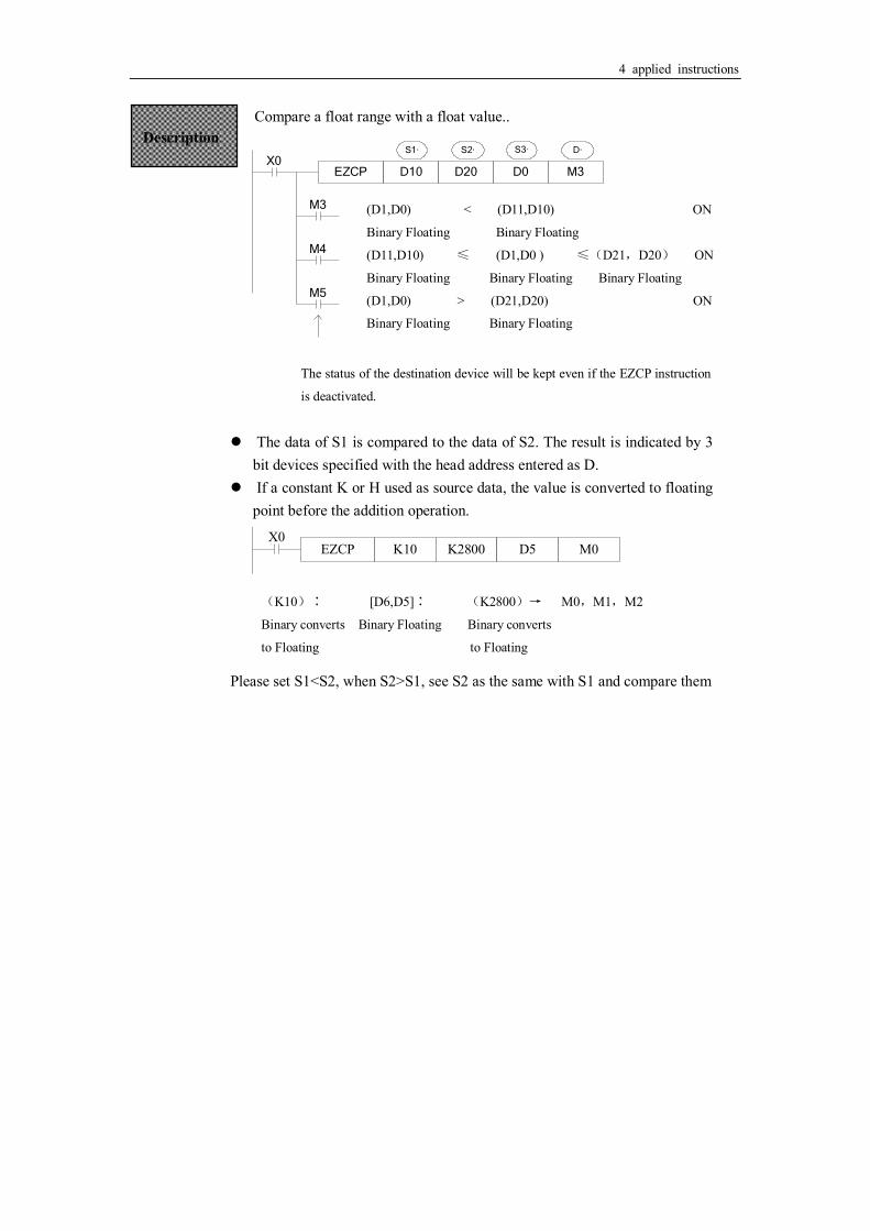
4 applied instructions
Compare a float range with a float value..
EZCP D10 D20 D0
M3
M4
M5
X0S1· S2·
M3
S3· D·
EZCP K10 K2800 D5 M0X0
Description
(D1,D0) < (D11,D10) ON
Binary Floating Binary Floating
(D11,D10) ≤ (D1,D0 ) ≤(D21,D20) ON
Binary Floating Binary Floating Binary Floating
(D1,D0) > (D21,D20) ON
Binary Floating Binary Floating
The status of the destination device will be kept even if the EZCP instruction
is deactivated.
The data of S1 is compared to the data of S2. The result is indicated by 3 bit devices specified with the head address entered as D.
If a constant K or H used as source data, the value is converted to floating point before the addition operation.
(K10)∶ [D6,D5]∶ (K2800)→ M0,M1,M2
Binary converts Binary Floating Binary converts
to Floating to Floating
Please set S1<S2, when S2>S1, see S2 as the same with S1 and compare them

4 applied instructions
4-9-3.Float Add[EADD] 1. Summary
Float Add [EADD] 16 bits - 32 bits EADD Execution
condition
Normally ON/OFF, rising/falling edge
Suitable
Models
XC2.XC3.XC5.XCM
Hardware
requirement
- Software
requirement
-
2. Operands
Operands Function Data Type
S1 Soft element address need to add 32 bits, BIN S2 Soft element address need to add 32 bits, BIN D Result address 32 bits, BIN
3. Suitable soft components
EADD D10 D20 D50
S1· S2· D·X0
EADD D100 K1234 D110X1
Operands System Constant Module
D FD ED TD CD DX DY DM DS K /H ID QD
S1 ● ● ● ● ● ● ●
S2 ● ● ● ● ● ● ●
D ● ● ● ●
Word
Description
(D11,D10) + (D21,D20) → (D51,D50)
Binary Floating Binary Floating Binary Floating
The floating point values stored in the source devices S1 and S2 are algebraically added and the result stored in the destination device D.
If a constant K or H used as source data, the value is converted to floating point before the addition operation.
(K1234) + ( D101,D100) → (D111,D110)
Binary converts to Floating Binary Floating Binary Floating
The same device may be used as a source and as the destination. If this is the case then, on continuous operation of the EADD instruction, the result of the previous operation will be used as a new source value and a new result calculated. This will happen every program scan unless the pulse modifier or an interlock program is used.

4 applied instructions
4-9-4.Float Sub[ESUB] 1. Summary
Float Sub [ESUB] 16 bits - 32 bits ESUB Execution
condition
Normally ON/OFF, rising/falling edge
Suitable
Models
XC2.XC3.XC5.XCM
Hardware
requirement
- Software
requirement
-
2. Operands
Operands Function Data Type
S1 Soft element address need to subtract 32 bits, BIN S2 Soft element address need to subtract 32 bits, BIN D Result address 32 bits, BIN
3. Suitable soft components
ESUB D10 D20 D50
S1· S2· D·X0
ESUB D100K1234 D110X1
Operands System Constant Module
D FD ED TD CD DX DY DM DS K /H ID QD
S1 ● ● ● ● ● ● ●
S2 ● ● ● ● ● ● ●
D ● ● ● ●
Word
Description
(D11,D10) - (D21,D20) → (D51,D50)
Binary Floating Binary Floating Binary Floating
The floating point value of S2 is subtracted from the floating point value of S1 and the result stored in destination device D.
If a constant K or H used as source data, the value is converted to floating point before the addition operation。
(K1234) - (D101,D100) → (D111,D110)
Binary converts to Floating Binary Floating Binary Floating
The same device may be used as a source and as the destination. If this is the case then, on continuous operation of the EADD instruction, the result of the previous operation will be used as a new source value and a new result calculated. This will happen every program scan unless the pulse modifier or an interlock program is used.

4 applied instructions
4-9-5.Float Mul[EMUL] 1. Summary
Float Multiply [EMUL] 16 bits - 32 bits EMUL Execution
condition
Normally ON/OFF, rising/falling edge
Suitable
Models
XC2.XC3.XC5.XCM
Hardware
requirement
- Software
requirement
-
2. Operands
Operands Function Data Type
S1 Soft element address need to multiply 32 bits, BIN S2 Soft element address need to multiply 32 bits, BIN D Result address 32 bits, BIN
3. Suitable soft components
EMUL D10 D20 D50
S1· S2· D·X0
EMUL D100K100 D110X1
Operands System Constant Module
D FD ED TD CD DX DY DM DS K /H ID QD
S1 ● ● ● ● ● ● ●
S2 ● ● ● ● ● ● ●
D ● ● ● ●
Word
Description
(D11,D10) × (D21,D20)→ (D51,D50)
Binary Floating Binary Floating Binary Floating
The floating value of S1 is multiplied with the floating value point value of S2. The result of the multiplication is stored at D as a floating value
If a constant K or H used as source data, the value is converted to floating point before the addition operation.
(K100) × (D101,D100) → (D111,D110)
Binary converts to Floating Binary Floating Binary Floating
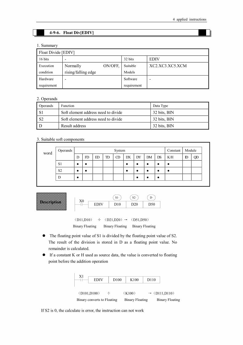
4 applied instructions
4-9-6.Float Div[EDIV] 1. Summary
Float Divide [EDIV] 16 bits - 32 bits EDIV Execution
condition
Normally ON/OFF, rising/falling edge
Suitable
Models
XC2.XC3.XC5.XCM
Hardware
requirement
- Software
requirement
-
2. Operands
Operands Function Data Type
S1 Soft element address need to divide 32 bits, BIN S2 Soft element address need to divide 32 bits, BIN D Result address 32 bits, BIN
3. Suitable soft components
EDIV D10 D20 D50
S1· S2· D·X0
EDIV D100 K100 D110X1
Operands System Constant Module
D FD ED TD CD DX DY DM DS K /H ID QD
S1 ● ● ● ● ● ● ●
S2 ● ● ● ● ● ● ●
D ● ● ● ●
word
Description
(D11,D10) ÷ (D21,D20)→ (D51,D50)
Binary Floating Binary Floating Binary Floating
The floating point value of S1 is divided by the floating point value of S2. The result of the division is stored in D as a floating point value. No remainder is calculated.
If a constant K or H used as source data, the value is converted to floating point before the addition operation
(D101,D100) ÷ (K100) →(D111,D110)
Binary converts to Floating Binary Floating Binary Floating
If S2 is 0, the calculate is error, the instruction can not work

4 applied instructions
4-9-7.Float Square Root [ESQR] 1. Summary
Float Square Root [ESQR] 16 bits - 32 bits ESQR Execution
condition
Normally ON/OFF, rising/falling edge
Suitable
Models
XC2.XC3.XC5.XCM
Hardware
requirement
- Software
requirement
-
2. Operands
Operands Function Data Type
S The soft element address need to do square root 32 bits, BIN D The result address 32 bits, BIN
3. Suitable soft components
ESQR D10 D20X0
S· D·
ESQR K1024 D110X1
Operands System Constant Module
D FD ED TD CD DX DY DM DS K /H ID QD
S ● ● ● ● ● ● ●
D ● ● ● ●
Word
(D11,D10) →(D21,D20)
Binary Floating Binary Floating Description
A square root is performed on the floating point value in S the result is stored in D If a constant K or H used as source data, the value is converted to floating point before
the addition operation.
(K1024) → (D111,D110)
Binary converts to Floating Binary Floating
When the result is zero, zero flag activates. Only when the source data is positive will the operation be effective. If S is negative
then an error occurs and error flag M8067 is set ON, the instruction can’t be executed.

4 applied instructions
4-9-8.Sine[SIN] 1. Summary
Float Sine[SIN] 16 bits - 32 bits SIN Execution
condition
Normally ON/OFF, rising/falling edge
Suitable
Models
XC2.XC3.XC5.XCM
Hardware
requirement
- Software
requirement
-
2. Operands
Operands Function Data Type
S The soft element address need to do sine 32 bits, BIN D The result address 32 bits, BIN
3. Suitable soft components
SIN D50 D60X0
S· D·
D51 D50
D61 D60
S·
D·
Operands System Constant Module
D FD ED TD CD DX DY DM DS K /H ID QD
S ● ● ● ● ● ● ●
D ● ● ● ●
Word
Description
(D51,D50) → (D61,D60)SIN
Binary Floating Binary Floating
This instruction performs the mathematical SIN operation on the floating point value in S (angle RAD). The result is stored in D.
RAD value (angle×π/180)
Assign the binary floating value
SIN value
Binary Floating

4 applied instructions
4-9-9.Cosine[SIN] 1. Summary
Float Cosine[COS] 16 bits - 32 bits COS Execution
condition
Normally ON/OFF, rising/falling edge
Suitable
Models
XC2.XC3.XC5.XCM
Hardware
requirement
- Software
requirement
-
2. Operands
Operands Function Data Type
S Soft element address need to do cos 32 bits, BIN D Result address 32 bits, BIN
3. Suitable soft components
COS D50 D60X0
S· D·
D51 D50
D61 D60
S·
D·
Operands System Constant Module
D FD ED TD CD DX DY DM DS K /H ID QD
S ● ● ● ● ● ● ●
D ● ● ● ●
Word
Description
(D51,D50)RAD → (D61,D60)COS
Binary Floating Binary Floating
This instruction performs the mathematical COS operation on the floating point value in S (angle RAD). The result is stored in D。
RAD value (angle×π/180)
Assign the binary floating value
COS value
Binary Floating
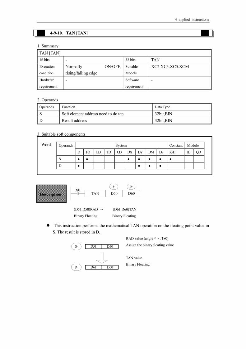
4 applied instructions
4-9-10.TAN [TAN] 1. Summary
TAN [TAN] 16 bits - 32 bits TAN Execution
condition
Normally ON/OFF, rising/falling edge
Suitable
Models
XC2.XC3.XC5.XCM
Hardware
requirement
- Software
requirement
-
2. Operands
Operands Function Data Type
S Soft element address need to do tan 32bit,BIN D Result address 32bit,BIN
3. Suitable soft components
TAN D50 D60X0
S· D·
D51 D50
D61 D60
S·
D·
Word Operands System Constant Module
D FD ED TD CD DX DY DM DS K /H ID QD
S ● ● ● ● ● ● ●
D ● ● ● ●
Description
(D51,D50)RAD → (D61,D60)TAN
Binary Floating Binary Floating
This instruction performs the mathematical TAN operation on the floating point value in S. The result is stored in D.
RAD value (angle×π/180)
Assign the binary floating value
TAN value
Binary Floating

4 applied instructions
4-9-11.ASIN [ASIN] 1. Summary
ASIN [ASIN] 16 bits - 32 bits ASIN Execution
condition
Normally ON/OFF, rising/falling edge
Suitable
Models
XC2.XC3.XC5.XCM
Hardware
requirement
V3.0 and above version Software
requirement
-
2. Operands
Operands Function Data Type
S Soft element address need to do arcsin 32 bits, BIN D Result address 32 bits, BIN
3. Suitable soft components
ASIN D50 D60X0
S· D·
D51 D50
D61 D60
S·
D·
Operands System Constant Module
D FD ED TD CD DX DY DM DS K /H ID QD
S ● ● ● ● ● ● ●
D ● ● ● ●
Word
Description
(D51,D50)ASIN → (D61,D60)RAD
Binary Floating Binary Floating
This instruction performs the mathematical ASIN operation on the floating point value in S. The result is stored in D.
ASIN value
Binary Floating
RAD value (angle×π/180)
Assign the binary floating value

4 applied instructions
4-9-12.ACOS [ACOS] 1. Summary
ACOS [ACOS] 16 bits - 32 bits ACOS Execution
condition
Normally ON/OFF, rising/falling edge
Suitable
Models
XC2.XC3.XC5.XCM
Hardware
requirement
V3.0 and above Software
requirement
-
2. Operands
Operands Function Data Type
S Soft element address need to do arccos 32 bits, BIN D Result address 32 bits, BIN
3. Suitable soft components
ACOS D50 D60X0
S· D·
D51 D50
D61 D60
S·
D·
Operands System Constant Module
D FD ED TD CD DX DY DM DS K /H ID QD
S ● ● ● ● ● ● ●
D ● ● ● ●
Word
Description
(D51,D50)ACOS → (D61,D60)RAD
Binary Floating Binary Floating
Calculate the arcos value(radian), save the result in the target address
TCOS value
Binary Floating
RAD value (angle×π/180)
Assign the binary floating value

4 applied instructions
4-9-13.ATAN [ATAN] 1. Summary
ATAN [ATAN] 16 bits - 32 bits ACOS Execution
condition
Normally ON/OFF, rising/falling edge
Suitable
Models
XC2.XC3.XC5.XCM
Hardware
requirement
V3.0 and above Software
requirement
-
2. Operands
Operands Function Data Type
S Soft element address need to do arctan 32 bit, BIN D Result address 32 bit, BIN
3.Suitable soft components
ATAN D50 D60X0
S· D·
D51 D50
D61 D60
S·
D·
Operands System Constant Module
D FD ED TD CD DX DY DM DS K /H ID QD
S ● ● ● ● ● ● ●
D ● ● ● ●
Word
Description
(D51,D50)ATAN → (D61,D60)RAD
Binary Floating Binary Floating
Calculate the arctan value ( radian), save the result in the target address
ATAN value
Binary Floating
RAD value (angle×π/180)
Assign the binary floating value

4 applied instructions
4-10.RTC Instructions
Mnemonic Function Chapter TRD Clock data read 4-10-1 TWR Clock data write 4-10-2
※1: To use the instructions, The Model should be equipped with RTC function;

4 applied instructions
4-10-1.Read the clock data [TRD] 1. Instruction Summary
Read the clock data: Read the clock data: [TRD] 16 bits TRD 32 bits - Execution
condition
Normally ON/OFF, rising/falling edge
Suitable
Models
XC2.XC3.XC5.XCM
Hardware
requirement
V2.51 and above Software
requirement
-
2. Operands
Operands Function Data Type
D Register to save clock data 16 bits, BIN 3. Suitable Soft Components
TRD D0X0
D·
Read PLC’s real time clock according to the following format.
The reading source is the special data register (D8013~D8019) which save clock data.
Word Operands System Constant Module
D FD ED TD CD DX DY DM DS K /H ID QD
D ● ● ●
Functions And Actions
The current time and date of the real time clock are read and stored in the 7 data devices specified by the head address D.
Unit Item
D0 Year
D1 Month
D2 Date
D3 Hour
D4 Minute
D5 Second
D Week
Unit Item Clock data
Special data register for real tim
e clock t
D8018 Year 0-99
D8017 Month 1-12
D8016 Date 1-31
D8015 Hour 0-23
D8014 Minute 0-59
D8013 Second 0-59
D8019 Week 0 (Sun.)-6 (Sat.)

4 applied instructions
4-10-2.Write Clock Data [TWR] 1. Instruction Summary
Write the clock data: Write clock data [TRD] 16 bits - 32 bits TRD Execution
condition
Normally ON/OFF, rising/falling edge
Suitable
Models
XC2.XC3.XC5.XCM
Hardware
requirement
V2.51 and above Software
requirement
-
2. Operands
Operands Function Data Type
S Write the clock data to the register 16 bits, BIN 3. Suitable Soft Components
TWR D0X0
S·
Word Operands System Constant Module
D FD ED TD CD DX DY DM DS K /H ID QD
S ● ● ● ● ● ● ● ●
The 7 data devices specified with the head
address S are used to set a new current value of
the real time clock.
Functions And Actions
Write the set clock data into PLC’s real time clock. In order to write real time clock, the 7 data devices specified with the head address should be pre-set.
S·
Unit Item Clock data
Data for clock setting
D10 Year 0-99
D11 Month 1-12
D12 Date 1-31
D13 Hour 0-23
D14 Minute 0-59
D15 Second 0-59
D16 Week 0 (Sun.)-6 (Sat.)
Unit Item
D8018 Year Special data register for real tim
e clock t
D8017 Month
D8016 Date
D8015 Hour
D8014 Minute
D8013 Second
D8019 Week

4 applied instructions
After executing TWR instruction, the time in real time clock will immediately change to be the new set time. So, when setting the time it is a good idea to set the source data to a time a number of minutes ahead and then drive the instruction when the real time reaches this value.

4 applied instructions