YZF-R1…limit of YZF-R1: 202 kg (445 lb)/YZF-R1C: 201 kg (443 lb). When loading within this weight...
133
5PW-28199-10 LIT-11626-15-47 YZF-R1P YZF-R1PC OWNER’S MANUAL
Transcript of YZF-R1…limit of YZF-R1: 202 kg (445 lb)/YZF-R1C: 201 kg (443 lb). When loading within this weight...

PRINTED IN JAPAN2001 . 12 - 7.0 × 2 CR
(E)
PRINTED ON RECYCLED PAPER
YAMAHA MOTOR CO., LTD.
5PW-28199-10LIT-11626-15-47
YZF-R1PYZF-R1PC
OWNER’S MANUAL

EAU03438
00002
1-INTRODUCTION
-R1 / YZF-R1C. This model ison of fine sporting, touring, and degree of craftsmanship andlds.
peration, inspection, and basictions concerning the operationYamaha dealer.
cle fully comply with the emis- manufacture. Yamaha has metr economy of operation of the important that you and youred maintenance schedules and
U5PW10.book Page 1 Thursday, January 10, 2002 12:15 PM
EAU
Congratulations on your purchase of the Yamaha YZFthe result of Yamaha’s vast experience in the productipacesetting racing machines. It represents the highreliability that have made Yamaha a leader in these fie
This manual will give you an understanding of the omaintenance of this motorcycle. If you have any quesor maintenance of your motorcycle, please consult a
The design and manufacture of this Yamaha motorcysions standards for clean air applicable at the date ofthese standards without reducing the performance omotorcycle. To maintain these high standards, it isYamaha dealer pay close attention to the recommendoperating instructions contained within this manual.

EAU00003PORTANT MANUAL INFORMATION
ticularly important information is distinguished in this manual by the following notations:
ERT! YOUR SAFETY IS
U5PW10.book Page 1 Thursday, January 10, 2002 12:15 PM
1-IM
Par
re injury or death to thepairing the motorcycle.
to avoid damage to the
learer.
torcycle and should remain
d quality. Therefore, whilelable at the time of printing,d this manual. If you haveaha dealer.
C
N
The Safety Alert Symbol meINVOLVED!
WARNING Failure to follow WARNING inmotorcycle operator, a bystan
AUTION: A CAUTION indicates specialmotorcycle.
OTE: A NOTE provides key informati
NOTE:_
� This manual should be considwith it even if the motorcycle
� Yamaha continually seeks adthis manual contains the mosthere may be minor discrepaany questions concerning this
_
ans ATTENTION! BECOME AL
structions could result in seveder or a person inspecting or re
precautions that must be taken
on to make procedures easier or c
ered a permanent part of this mois subsequently sold.vancements in product design ant current product information avaincies between your motorcycle an manual, please consult your Yam

IMPORTANT MANUAL INFORMATIONEW000000
IS MANUAL AND THE “YOU AND YOUR MOTORCYCLE: RIDINGAREFULLY AND COMPLETELY BEFORE OPERATING THIS MOTOR-TTEMPT TO OPERATE THIS MOTORCYCLE UNTIL YOU HAVE AT-E KNOWLEDGE OF ITS CONTROLS AND OPERATING FEATURESAVE BEEN TRAINED IN SAFE AND PROPER RIDING TECHNIQUES.TIONS AND CAREFUL MAINTENANCE, ALONG WITH GOOD RIDINGURE THAT YOU SAFELY ENJOY THE CAPABILITIES AND THE RELI-OTORCYCLE.
U5PW10.book Page 2 Thursday, January 10, 2002 12:15 PM
WARNING_
PLEASE READ THTIPS” BOOKLET CCYCLE. DO NOT ATAINED ADEQUATAND UNTIL YOU HREGULAR INSPECSKILLS, WILL ENSABILITY OF THIS M_

IMPORTANT MANUAL INFORMATION
AFFIX DEALER
EAU04247
©2001
Aw
Y
U5PW10.book Page 3 Thursday, January 10, 2002 12:15 PM
LABEL HERE
YZF-R1P/YZF-R1PCOWNER’S MANUAL
by Yamaha Motor Corporation, U.S.A.1st edition, November 2001
All rights reserved.ny reprinting or unauthorized useithout the written permission of
amaha Motor Corporation, U.S.A.is expressly prohibited.
Printed in Japan.P/N LIT-11626-15-47

LE OF CONTENTS
1
2
FUNCTIONS 3
4
T RIDING POINTS 5
D MINOR REPAIR 6
ORAGE 7
8
9
EAU00009
U5PW10.book
TAB
1 SAFETY INFORMATION
2 DESCRIPTION
3 INSTRUMENT AND CONTROL
4 PRE-OPERATION CHECKS
5 OPERATION AND IMPORTAN
6 PERIODIC MAINTENANCE AN
7 MOTORCYCLE CARE AND ST
8 SPECIFICATIONS
9 CONSUMER INFORMATION
Page 1 Thursday, January 10, 2002 12:15 PM
INDEX

SAFETY INFORMATION
1
Safe riding .......................................................................................... 1-1Protective apparel .............................................................................. 1-3Modifications ...................................................................................... 1-3Loading and accessories ................................................................... 1-3Gasoline and exhaust gas.................................................................. 1-5Location of important labels .............................................................. 1-7
U5PW10.book Page 1 Thursday, January 10, 2002 12:15 PM

1
EAU04193
USE AND OPERATION ARE DE-AS WELL AS THE EXPERTISE OF
LLOWING REQUIREMENTS BE-
U5PW10.book Page 1 Thursday, January 10, 2002 12:15 PM
SOURCE ON ALL ASPECTS OF
IREMENTS IN THE OWNER’S
G TECHNIQUES.TED BY THE OWNER’S MANUALITIONS.
event an accident.er.raffic is the predominating cause ofaused by an automobile driver whos to be very effective in reducing the
rough intersections, since intersec-ccur.her motorist’s blind spot.
1-1
1-SAFETY INFORMATION
MOTORCYCLES ARE SINGLE TRACK VEHICLES. THEIR SAFEPENDENT UPON THE USE OF PROPER RIDING TECHNIQUES THE OPERATOR. EVERY OPERATOR SHOULD KNOW THE FOFORE RIDING THIS MOTORCYCLE.HE OR SHE SHOULD:1. OBTAIN THOROUGH INSTRUCTIONS FROM A COMPETENT
MOTORCYCLE OPERATION.2. OBSERVE THE WARNINGS AND MAINTENANCE REQU
MANUAL.3. OBTAIN QUALIFIED TRAINING IN SAFE AND PROPER RIDIN4. OBTAIN PROFESSIONAL TECHNICAL SERVICE AS INDICA
AND/OR WHEN MADE NECESSARY BY MECHANICAL COND
Safe riding
1. Always make pre-operation checks. Careful checks may help pr2. This motorcycle is designed to carry the operator and a passeng3. The failure of motorists to detect and recognize motorcycles in t
automobile/motorcycle accidents. Many accidents have been cdid not see the motorcycle. Making yourself conspicuous appearchance of this type of accident.
Therefore:a. Wear a brightly colored jacket.b. Use extra caution when you are approaching and passing th
tions are the most likely places for motorcycle accidents to oc. Ride where other motorists can see you. Avoid riding in anot

FETY INFORMATION
1
operators who have been involved in
r motorcycle to other qualified opera-
elp you to avoid an accident.here there is no traffic until you have controls.perator. A typical error made by the or undercornering (insufficient lean
rranted by road and traffic conditions.that other motorists can see you.er control.d both feet on the operator footrests
at strap or grab bar, if equipped, with
both feet on the passenger footrests.
le for off-road use.
U5PW10.book Page 2 Thursday, January 10, 2002 12:15 PM
SA
1-2
4. Many accidents involve inexperienced operators. In fact, many accidents do not even have a current motorcycle license.a. Make sure that you are qualified and that you only lend you
tors.b. Know your skills and limits. Staying within your limits may hc. We recommend that you practice riding your motorcycle w
become thoroughly familiar with the motorcycle and all of its5. Many accidents have been caused by error of the motorcycle o
operator is veering wide on a turn due to EXCESSIVE SPEEDangle for the speed).a. Always obey the speed limit and never travel faster than wab. Always signal before turning or changing lanes. Make sure
6. The posture of the operator and passenger is important for propa. The operator should keep both hands on the handlebar an
during operation to maintain control of the motorcycle.b. The passenger should always hold onto the operator, the se
both hands and keep both feet on the passenger footrests.c. Never carry a passenger unless he or she can firmly place
7. Never ride under the influence of alcohol or other drugs.8. This motorcycle is designed for on-road use only. It is not suitab

1
f head injuries. The use of a safety of head injuries.
ld contribute to an impairment of vi-
tive in preventing or reducing abra-
e control levers, footrests, or wheels
ion. They become very hot and cangs, ankles, and feet.
r the removal of original equipment,rsonal injury. Modifications may also
t stability and handling if the weightf an accident, use extreme cautione when riding a motorcycle that hasollow if loading cargo or adding ac-
U5PW10.book Page 3 Thursday, January 10, 2002 12:15 PM
SAFETY INFORMATION
1-3
Protective apparel
The majority of fatalities from motorcycle accidents are the result ohelmet is the single most critical factor in the prevention or reduction1. Always wear an approved helmet.2. Wear a face shield or goggles. Wind in your unprotected eyes cou
sion that could delay seeing a hazard.3. The use of a jacket, heavy boots, trousers, gloves, etc., is effec
sions or lacerations.4. Never wear loose-fitting clothes, otherwise they could catch on th
and cause injury or an accident.5. Never touch the engine or exhaust system during or after operat
cause burns. Always wear protective clothing that covers your le6. A passenger should also observe the above precautions.
Modifications
Modifications made to this motorcycle not approved by Yamaha, omay render the motorcycle unsafe for use and may cause severe pemake your motorcycle illegal to use.
Loading and accessories
Adding accessories or cargo to your motorcycle can adversely affecdistribution of the motorcycle is changed. To avoid the possibility owhen adding cargo or accessories to your motorcycle. Use extra caradded cargo or accessories. Here are some general guidelines to fcessories to your motorcycle:

FETY INFORMATION
1
must not exceed the maximum load loading within this weight limit, keep
to the motorcycle as possible. Make of the motorcycle to minimize imbal-
t accessories and cargo are securelynts and cargo restraints frequently.ork, or front fender. These items, in-n create unstable handling or a slow
for use on this motorcycle. Sinceu must personally be responsible fors. Use extreme caution when select-
der “Loading” when mounting acces-
rformance of your motorcycle. Care- does not in any way reduce grounding travel or control operation, or ob-
U5PW10.book Page 4 Thursday, January 10, 2002 12:15 PM
SA
1-4
LoadingThe total weight of the operator, passenger, accessories and cargolimit of YZF-R1: 202 kg (445 lb)/YZF-R1C: 201 kg (443 lb). Whenthe following in mind:1. Cargo and accessory weight should be kept as low and close
sure to distribute the weight as evenly as possible on both sidesance or instability.
2. Shifting weights can create a sudden imbalance. Make sure thaattached to the motorcycle before riding. Check accessory mou
3. Never attach any large or heavy items to the handlebar, front fcluding such cargo as sleeping bags, duffel bags, or tents, casteering response.
Accessories
Genuine Yamaha accessories have been specifically designedYamaha cannot test all other accessories that may be available, yothe proper selection, installation and use of non-Yamaha accessorieing and installing any accessories.Keep the following guidelines in mind, as well as those provided unsories.1. Never install accessories or carry cargo that would impair the pe
fully inspect the accessory before using it to make sure that itclearance or cornering clearance, limit suspension travel, steerscure lights or reflectors.

1
n create instability due to improperare added to the handlebar or front be kept to a minimum. the motorcycle due to aerodynamicycle may become unstable in cross
assing or being passed by large ve-
normal riding position. This improp-d may limit control ability, therefore,
essories exceed the capacity of theich could cause a dangerous loss of
system when refueling..d area. The exhaust fumes are poi- a short time. Always operate your
nded and remove the key from the
U5PW10.book Page 5 Thursday, January 10, 2002 12:15 PM
SAFETY INFORMATION
1-5
a. Accessories fitted to the handlebar or the front fork area caweight distribution or aerodynamic changes. If accessories fork area, they must be as lightweight as possible and should
b. Bulky or large accessories may seriously affect the stability ofeffects. Wind may attempt to lift the motorcycle, or the motorcwinds. These accessories may also cause instability when phicles.
c. Certain accessories can displace the operator from his or herer position limits the freedom of movement of the operator ansuch accessories are not recommended.
2. Use caution when adding electrical accessories. If electrical accmotorcycle’s electrical system an electric failure could result, whlights or engine power.
Gasoline and exhaust gas
1. GASOLINE IS HIGHLY FLAMMABLE:a. Always turn the engine off when refueling.b. Take care not to spill any gasoline on the engine or exhaust c. Never refuel while smoking or in the vicinity of an open flame
2. Never start the engine or let it run for any length of time in a closesonous and may cause loss of consciousness and death withinmotorcycle in an area that has adequate ventilation.
3. Always turn the engine off before leaving the motorcycle unattemain switch. When parking the motorcycle, note the following:
FETY INFORMATION
1
the motorcycle in a place where pe-
wise it may fall over., a kerosene heater, or near an open
re that it is kept upright. If the motor-
or, or allow gasoline to get into yourr skin or clothing, immediately wash
.
U5PW10.book Page 6 Thursday, January 10, 2002 12:15 PM
SA
1-6
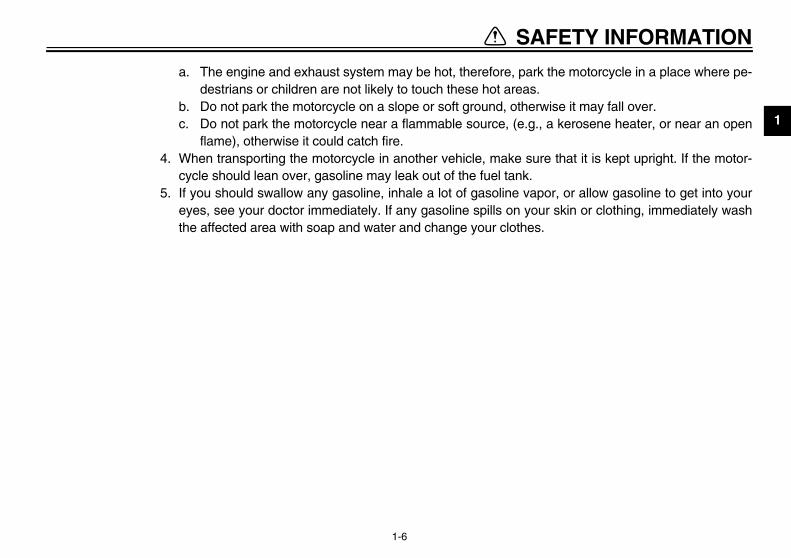
a. The engine and exhaust system may be hot, therefore, parkdestrians or children are not likely to touch these hot areas.
b. Do not park the motorcycle on a slope or soft ground, otherc. Do not park the motorcycle near a flammable source, (e.g.
flame), otherwise it could catch fire.4. When transporting the motorcycle in another vehicle, make su
cycle should lean over, gasoline may leak out of the fuel tank.5. If you should swallow any gasoline, inhale a lot of gasoline vap
eyes, see your doctor immediately. If any gasoline spills on youthe affected area with soap and water and change your clothes
1
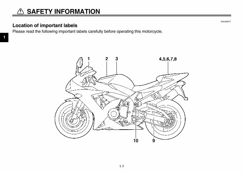
EAU02977
LoPle
U5PW10.book Page 7 Thursday, January 10, 2002 12:15 PM
SAFETY INFORMATION
1-7
cation of important labels ase read the following important labels carefully before operating this motorcycle.

TY INFORMATION
1
1
3
4
5
2
U5PW10.book Page 8 Thursday, January 10, 2002 12:15 PM
SAFE
1-8
California only6
7
CAUTIONCleaning with alkaline oracid cleaner, gasoline orsolvent will damagewindshield.Use neutral detergent.
5LV-2835Y-00
PREMIUM UNLEADED GASOLINE ONLY91 Min. Pump Octane (R+M) 2
5PW-2415E-10

1
8
9
10
U5PW10.book Page 9 Thursday, January 10, 2002 12:15 PM
SAFETY INFORMATION
1-9

DESCRIPTION
2
Left view ............................................................................................. 2-1Right view........................................................................................... 2-2Controls and instruments ................................................................... 2-3
U5PW10.book Page 1 Thursday, January 10, 2002 12:15 PM

2
EAU00026
U5PW10.book Page 1 Thursday, January 10, 2002 12:15 PM
2-DE
Le
)))))))
)))
1.2.3.4.5.6.7.8.9.
10.11.
2-1
SCRIPTION
ft view
Fuse box (page 6-40Front fork compression damping force adjusting screw (page 3-19Front fork rebound damping force adjusting screw (page 3-19Front fork spring preload adjusting bolt (page 3-18Front brake fluid reservoir (page 6-31Shock absorber assembly spring preload adjusting ring (page 3-20Shock absorber assembly compression damping force adjusting screw (page 3-21Owner’s tool kit (page 6-1)Shock absorber assembly rebound damping force adjusting screw (page 3-21Engine oil drain bolt (page 6-14Engine oil filter cartridge (page 6-15
DESCRIPTION
2
R
121314151617
(page 6-21)(page 6-18)(page 6-18)
ck window (page 6-14)(page 6-14)
U5PW10.book Page 2 Thursday, January 10, 2002 12:15 PM
2-2
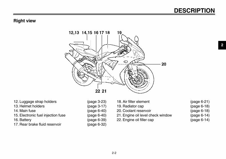
ight view
. Luggage strap holders (page 3-23)
. Helmet holders (page 3-17)
. Main fuse (page 6-40)
. Electronic fuel injection fuse (page 6-40)
. Battery (page 6-39)
. Rear brake fluid reservoir (page 6-32)
18. Air filter element19. Radiator cap20. Coolant reservoir21. Engine oil level che22. Engine oil filler cap

DE
2
Co
1.2.3.4.
(page 3-11)ches (page 3-12)
(page 6-23)(page 3-13)
U5PW10.book Page 3 Thursday, January 10, 2002 12:15 PM
SCRIPTION
2-3
ntrols and instruments
Clutch lever (page 3-12)Left handlebar switches (page 3-11)Multi-function display (page 3-6)Main switch/steering lock (page 3-1)
5. Tachometer6. Right handlebar swit7. Throttle grip8. Brake lever
3
INSTRUMENT AND CONTROL FUNCTIONS
Main switch/steering lock .....................................3-1Indicator and warning lights ................................3-2Multi-function display ...........................................3-6Tachometer ........................................................3-11Handlebar switches ...........................................3-11Clutch lever ........................................................3-12Shift pedal ..........................................................3-12Brake lever .........................................................3-13Brake pedal ........................................................3-13Fuel tank cap .....................................................3-13Fuel ....................................................................3-14
Catalytic converter ............................................ 3-15Seats ................................................................. 3-15Helmet holders .................................................. 3-17Storage compartment ....................................... 3-17Adjusting the front fork ...................................... 3-18Adjusting the shock absorber assembly ............ 3-20Luggage strap holders ...................................... 3-23EXUP system .................................................... 3-23Sidestand .......................................................... 3-23Ignition circuit cut-off system ............................. 3-24
U5PW10.book Page 1 Thursday, January 10, 2002 12:15 PM

3
EAU00027
U5PW10.book Page 1 Thursday, January 10, 2002 12:15 PM
3-IN
EAU00040
CK steering is locked, and all electricaltems are off. The key can be re-ved.
lock the steeringTurn the handlebars all the way tothe left.Push the key in from the “OFF” po-sition, and then turn it to “LOCK”while still pushing it.Remove the key.
unlock the steeringh the key in, and then turn it toF” while still pushing it.
MaThethe usepos
3-1
STRUMENT AND CONTROL FUNCTIONS
EAU00029
in switch/steering lock main switch/steering lock controlsignition and lighting systems, and isd to lock the steering. The variousitions are described below.
EAU04565
ONAll electrical circuits are supplied withpower, and the meter lighting, taillight,license plate light, auxiliary lights andposition lights come on, and the enginecan be started. The key cannot be re-moved.
NOTE:_
The headlights come on automaticallywhen the engine is started and stay onuntil the key is turned to “OFF”, even ifthe engine stalls. _
EAU00038
OFFAll electrical systems are off. The keycan be removed.
LOThesysmo
To 1.
2.
3.
To Pus“OF

NTROL FUNCTIONS
3
_
N“Lmsymaccyke_
EAU04303
el level warning light “ ” is warning light comes on when the
el level drops below approximately3 L (0.73 lmp gal, 0.87 US gal). Whenis occurs, refuel as soon as possible.e electrical circuit of the warning lightn be checked according to the fol-ing procedure.
. Turn the key to “ON”.
. If the warning light does not comeon for a few seconds, then go off,have a Yamaha dealer check theelectrical circuit.
1.2.
U5PW10.book Page 2 Thursday, January 10, 2002 12:15 PM
INSTRUMENT AND CO
3-2
EW000016
WARNINGever turn the key to “OFF” orOCK” while the motorcycle isoving, otherwise the electricalstems will be switched off, whichay result in loss of control or ancident. Make sure that the motor-cle is stopped before turning they to “OFF” or “LOCK”.
EAU03034
Indicator and warning lights
EAU04121
Turn signal indicator lights “ ”and “ ” The corresponding indicator light flash-es when the turn signal switch ispushed to the left or right.
FuThfu3.thThcalow
12
Push.Turn.
1. Right turn signal indicator light “ ”2. Fuel level warning light “ ”3. Oil level warning light “ ”4. Neutral indicator light “ ”5. Engine trouble warning light “ ”6. High beam indicator light “ ”7. Left turn signal indicator light “ ”

IN
3
OilThiengThecanlow
1.2.
EAU00063
h beam indicator light “ ” s indicator light comes on when theh beam of the headlight is switched
1. R2. F3. O4. N5. E6. H7. L
U5PW10.book Page 3 Thursday, January 10, 2002 12:15 PM
STRUMENT AND CONTROL FUNCTIONS
3-3
EAU04301
level warning light “ ” s warning light comes on when theine oil level is low. electrical circuit of the warning light be checked according to the fol-ing procedure.Turn the key to “ON”.If the warning light does not comeon for a few seconds, then go off,have a Yamaha dealer check theelectrical circuit.
NOTE:_
Even if the oil level is sufficient, thewarning light may flicker when riding ona slope or during sudden accelerationor deceleration, but this is not a mal-function. _
EAU00061
Neutral indicator light “ ” This indicator light comes on when thetransmission is in the neutral position.
EAU04514
Engine trouble warning light “ ” This warning light comes on or flasheswhen an electrical circuit monitoringthe engine is defective. When this oc-curs, have a Yamaha dealer check theself-diagnosis system.
NOTE:_
This warning light comes on for a fewseconds, then goes off when the key isturned to “ON”, but this does not indi-cate a malfunction. _
HigThihigon.
ight turn signal indicator light “ ”uel level warning light “ ”il level warning light “ ”eutral indicator light “ ”ngine trouble warning light “ ”igh beam indicator light “ ”eft turn signal indicator light “ ”
NTROL FUNCTIONS
3
EnThligfo
12
1.2.3.
U5PW10.book Page 4 Thursday, January 10, 2002 12:15 PM
INSTRUMENT AND CO
3-4
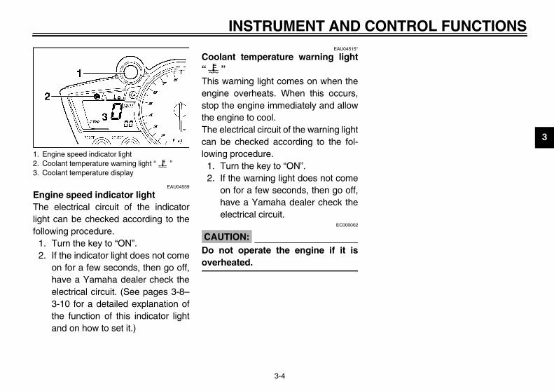
EAU04559
gine speed indicator light e electrical circuit of the indicatorht can be checked according to thellowing procedure.. Turn the key to “ON”.. If the indicator light does not come
on for a few seconds, then go off,have a Yamaha dealer check theelectrical circuit. (See pages 3-8–3-10 for a detailed explanation ofthe function of this indicator lightand on how to set it.)
EAU04515*
Coolant temperature warning light“ ” This warning light comes on when theengine overheats. When this occurs,stop the engine immediately and allowthe engine to cool.The electrical circuit of the warning lightcan be checked according to the fol-lowing procedure.
1. Turn the key to “ON”.2. If the warning light does not come
on for a few seconds, then go off,have a Yamaha dealer check theelectrical circuit.
EC000002
CAUTION:_
Do not operate the engine if it isoverheated. _
Engine speed indicator lightCoolant temperature warning light “ ”Coolant temperature display

IN
3
CB-25
What to do
OK. Go ahead with riding.
OK. Go ahead with riding.
Stop the motorcycle and allow it toidle until the coolant temperaturegoes down.If the temperature does not godown, stop the engine. (See the“Engine overheating” section onpage 6-51 for further instructions.)
Stop the engine and allow it to cool.(See the “Engine overheating” sec-tion on page 6-51 for further in-structions.)
U5PW10.book Page 5 Thursday, January 10, 2002 12:15 PM
STRUMENT AND CONTROL FUNCTIONS
3-5
E
Coolant temperature Display Conditions
0–39 °C(0–103 °F)
Message “LO” is displayed.
40–116 °C(104–242 °F)
Temperature is displayed.
117–139 °C(243–283 °F)
Temperature flashes.Warning light comes on.
Above 140 °C(284 °F)
Message “HI” flashes.Warning light comes on.

NTROL FUNCTIONS
3
MThw
dometer and tripmeter modesshing the “SELECT” button switches
e display between the odometerode “ODO” and the tripmeter modesRIP 1” and “TRIP 2” in the followingder:DO → TRIP 1 → TRIP 2 → ODO
the fuel level warning light comes onee page 3-2), the odometer displayll automatically change to the fuel re-rve tripmeter mode “F-TRIP” andrt counting the distance traveledm that point. In that case, pushing
e “SELECT” button switches the dis-y between the various tripmeter andometer modes in the following order:TRIP → TRIP 1 → TRIP 2 → ODO F-TRIP
1.2.3.
U5PW10.book Page 6 Thursday, January 10, 2002 12:15 PM
INSTRUMENT AND CO
3-6
EAU04566
ulti-function display e multi-function display is equipped
ith the following:� a speedometer (which shows the
riding speed)� an odometer (which shows the to-
tal distance traveled)� two tripmeters (which show the
distance traveled since they werelast set to zero)
� a fuel reserve tripmeter (whichshows the distance traveled sincethe fuel level warning light cameon)
� a clock� a self-diagnosis device� a display brightness and engine
speed indicator light control mode
NOTE:_
� Be sure to turn the key to “ON” be-fore using the “SELECT” and“RESET” buttons.
� To switch the speedometer andodometer/tripmeter displays be-tween kilometers and miles, pressthe “SELECT” button and“RESET” button together for atleast two seconds.
_
OPuthm“TorO
If (swisestafrothplaodF-→
Multi-function display“SELECT” button“RESET” button

IN
3
To ingpusoneresitseretuand
CloTurTo moleaTo moTo
1.
2.
ECA00127
UTION:the display indicates an errore, the motorcycle should becked as soon as possible in or- to avoid engine damage.
U5PW10.book Page 7 Thursday, January 10, 2002 12:15 PM
STRUMENT AND CONTROL FUNCTIONS
3-7
reset a tripmeter, select it by push- the “SELECT” button, and thenh the “RESET” button for at least second. If you do not reset the fuel
erve tripmeter manually, it will resetlf automatically and the display willrn to the prior mode after refueling traveling 5 km (3 mi).
ck moden the key to “ON”.change the display to the clock
de, push the “SELECT” button for atst one second.change the display back to the priorde, push the “SELECT” button.set the clock:
Push the “SELECT” button and“RESET” button together for atleast two seconds.When the hour digits start flashing,push the “RESET” button to setthe hours.
3. Push the “SELECT” button, andthe minute digits will start flashing.
4. Push the “RESET” button to setthe minutes.
5. Push the “SELECT” button andthen release it to start the clock.
Self-diagnosis deviceThis model is equipped with a self-di-agnosis device for various electrical cir-cuits.If any of those circuits are defective,the engine trouble warning light willcome on, and then the multi-functiondisplay will indicate a two-digit errorcode (e.g., 11, 12, 13).If the multi-function display indicatessuch an error code, note the code num-ber, and then have a Yamaha dealercheck the motorcycle.
CA_
If codcheder_

NTROL FUNCTIONS
3
DspThfulolo
1
TE:� To make any settings in this mode,
you have to cycle through all of itsfunctions. However, if the key isturned to “OFF” or the engine isstarted before completing the pro-cedure, only the settings made be-fore the “SELECT” button was lastpushed will be applied.
� In this mode, the multi-functiondisplay shows the current settingfor each function (except the en-gine speed indicator light activityfunction).
1.2.3.
U5PW10.book Page 8 Thursday, January 10, 2002 12:15 PM
INSTRUMENT AND CO
3-8
isplay brightness and engineeed indicator light control modeis mode cycles through five control
nctions, allowing you to make the fol-wing settings in the order listed be-w.. Display brightness: This function
allows you to adjust the brightnessof the multi-function display to suitthe outside lighting conditions.
2. Engine speed indicator light activi-ty: This function allows you tochoose whether or not the indica-tor light should be activated andwhether it should blink or stay onwhen activated.
3. Engine speed indicator light acti-vation: This function allows you toselect the engine speed at whichthe indicator light will be activated.
4. Engine speed indicator light deac-tivation: This function allows youto select the engine speed atwhich the indicator light will be de-activated.
5. Engine speed indicator lightbrightness: This function allowsyou to adjust the brightness of theindicator light to suit your prefer-ence.
NO_
_
Engine speed indicator light“SELECT” button“RESET” button

IN
3
To 1.2.
3.
4.
5.
set the engine speed indicator lightivation function
TE: indicator light activation function canset between 7,000 and 12,000 r/mincrements of 500 r/min.
Push the “RESET” button to selectthe desired engine speed for acti-vating the indicator light.Push the “SELECT” button to con-firm the selected engine speed.The control mode changes to theengine speed indicator light deac-tivation function.
U5PW10.book Page 9 Thursday, January 10, 2002 12:15 PM
STRUMENT AND CONTROL FUNCTIONS
3-9
adjust the display brightnessTurn the key to “OFF”.Push and hold the “SELECT” but-ton.Turn the key to “ON”, and then, af-ter five seconds, release the“SELECT” button.Push the “RESET” button to selectthe desired display brightness lev-el.Push the “SELECT” button to con-firm the selected display bright-ness level. The control modechanges to the engine speed indi-cator light activity function.
To set the engine speed indicator lightactivity function
1. Push the “RESET” button to selectone of the following indicator lightactivity settings:
a. The indicator light will stay onwhen activated. (This setting is se-lected when the indicator lightstays on.)
b. The indicator light will flash whenactivated. (This setting is selectedwhen the indicator light flashesfour times per second.)
c. The indicator light is deactivated;in other words, it will not come onor flash. (This setting is selectedwhen the indicator light flashesonce every two seconds.)
2. Push the “SELECT” button to con-firm the selected indicator light ac-tivity. The control mode changesto the engine speed indicator lightactivation function.
To act
NO_
Thebe in in_
1.
2.

NTROL FUNCTIONS
3
Tode
N_
_
1
2
U5PW10.book Page 10 Thursday, January 10, 2002 12:15 PM
INSTRUMENT AND CO
3-10
set the engine speed indicator lightactivation function
OTE:� The indicator light deactivation
function can be set between 7,000and 12,000 r/min in increments of500 r/min.
� Be sure to set the deactivationfunction to a higher engine speedthan for the activation function,otherwise the engine speed indi-cator light will remain deactivated.
. Push the “RESET” button to selectthe desired engine speed for de-activating the indicator light.
. Push the “SELECT” button to con-firm the selected engine speed.The control mode changes to theengine speed indicator light bright-ness function.
To adjust the engine speed indicatorlight brightness
1. Push the “RESET” button to selectthe desired indicator light bright-ness level.
2. Push the “SELECT” button to con-firm the selected indicator lightbrightness level. The multi-func-tion display will return to the odom-eter, tripmeter or clock mode.

IN
3
TaTheto mwit
CA_
DochoRe_
EAU03889
n signal switch “ / ” signal a right-hand turn, push thistch to “ ”. To signal a left-hand, push this switch to “ ”. Whenased, the switch returns to the cen-position. To cancel the turn signalts, push the switch in after it has re-ed to the center position.
EAU00129
rn switch “ ” ss this switch to sound the horn.
1. T2. T
U5PW10.book Page 11 Thursday, January 10, 2002 12:15 PM
STRUMENT AND CONTROL FUNCTIONS
3-11
EAU00101
chometer electric tachometer allows the rideronitor the engine speed and keep it
hin the ideal power range.EC000003
UTION: not operate the engine in the ta-meter red zone.
d zone: 11,750 r/min and above
EAU00118
Handlebar switches
EAU03888
Dimmer switch “ / ” Set this switch to “ ” for the highbeam and to “ ” for the low beam.
TurTo switurnreleter lighturn
HoPre
achometerachometer red zone
1. Dimmer switch “ / ”2. Turn signal switch “ / ”3. Horn switch “ ”

NTROL FUNCTIONS
3
EnSethstcytust
StPuw
C_
Setio_
EAU00157
ift pedal shift pedal is located on the left of the engine and is used in com-tion with the clutch lever when
ting the gears of the 6-speed con-t-mesh transmission equipped on
motorcycle.
1.2.
hift pedal
U5PW10.book Page 12 Thursday, January 10, 2002 12:15 PM
INSTRUMENT AND CO
3-12
EAU03890
gine stop switch “ / ” t this switch to “ ” before starting
e engine. Set this switch to “ ” toop the engine in case of an emergen-, such as when the motorcycle over-rns or when the throttle cable isuck.
EAU00143
art switch “ ” sh this switch to crank the engine
ith the starter.EC000005
AUTION:e page 5-1 for starting instruc-ns prior to starting the engine.
EAU00152
Clutch lever The clutch lever is located at the lefthandlebar grip. To disengage theclutch, pull the lever toward the handle-bar grip. To engage the clutch, releasethe lever. The lever should be pulledrapidly and released slowly for smoothclutch operation.The clutch lever is equipped with aclutch switch, which is part of the ignitioncircuit cut-off system. (See page 3-24for an explanation of the ignition circuitcut-off system.)
ShThesidebinashifstanthis
Engine stop switch “ / ”Start switch “ ”
1. Clutch lever 1. S

IN
3
BrThehanpulThetiontanhanwhfromthediathe
EAU04068
el tank cap
open the fuel tank capen the fuel tank cap lock cover, in-t the key into the lock, and then turn4 turn clockwise. The lock will be re-sed and the fuel tank cap can bened.
close the fuel tank capPush the fuel tank cap into posi-tion with the key inserted in thelock.Remove the key, and then closethe lock cover.
1. B2. B3. Aa. D
g
uel tank cap lock covernlock.
U5PW10.book Page 13 Thursday, January 10, 2002 12:15 PM
STRUMENT AND CONTROL FUNCTIONS
3-13
EAU00161
ake lever brake lever is located at the rightdlebar grip. To apply the front brake,
l the lever toward the handlebar grip. brake lever is equipped with a posi- adjusting dial. To adjust the dis-ce between the brake lever and thedlebar grip, turn the adjusting dial
ile holding the lever pushed away the handlebar grip. Make sure that
appropriate setting on the adjustingl is aligned with the arrow mark on brake lever.
EAU00162
Brake pedal The brake pedal is on the right side ofthe motorcycle. To apply the rearbrake, press down on the brake pedal.
Fu
To Opserit 1/leaope
To 1.
2.
rake leverrake lever position adjusting dialrrow markistance between brake lever and handlebar rip
1. Brake pedal 1. F2. U

TROL FUNCTIONS
3
N_
Thlethno_
_
Mpr_
EAU00185
TION:diately wipe off spilled fuela clean, dry, soft cloth, sinceay deteriorate painted surfac-
plastic parts.
EAU04567
ECA00104
TION:only unleaded gasoline. Thef leaded gasoline will cause se-damage to internal engine
, such as the valves and piston, as well as to the exhaust sys-
ommended fuel:REMIUM UNLEADED ASOLINE ONLYl tank capacity:otal amount:
17 L (3.74 Imp gal, 4.49 US gal)mount remaining when the fuel
evel warning light comes on:3.3 L (0.73 Imp gal, 0.87 US gal)
U5PW10.book Page 14 Thursday, January 10, 2002 12:15 PM
INSTRUMENT AND CON
3-14
OTE:e fuel tank cap cannot be closed un-
ss the key is in the lock. In addition,e key cannot be removed if the cap ist properly closed and locked.
EWA00025
WARNINGake sure that the fuel tank cap isoperly closed before riding.
EAU03753
Fuel Make sure that there is sufficient fuel inthe tank. Fill the fuel tank to the bottomof the filler tube as shown.
EW000130
WARNING_
� Do not overfill the fuel tank, oth-erwise it may overflow when thefuel warms up and expands.
� Avoid spilling fuel on the hotengine.
_
CAU_
Immewith fuel mes or_
CAU_
Use use overe partsringstem. _
1. Fuel tank filler tube2. Fuel level
RecPG
FueT
Al

IN
3
Yosigline[(Roctknogasumwillma
GaTheholingethtenconmecauhic
EAU04493
ats
er seat remove the rider seatl up the rear corners of the rider seatshown, remove the bolts, and thenl the seat off.
olt (× 2)
U5PW10.book Page 15 Thursday, January 10, 2002 12:15 PM
STRUMENT AND CONTROL FUNCTIONS
3-15
ur Yamaha engine has been de-ned to use regular unleaded gaso- with a pump octane number+M)/2] of 91 or higher, or a researchane number of 95 or higher. Ifcking (or pinging) occurs, use aoline of a different brand or premi- unleaded fuel. Use of unleaded fuel extend spark plug life and reduceintenance costs.
soholre are two types of gasohol: gaso-
containing ethanol and that contain- methanol. Gasohol containinganol can be used if the ethanol con-t does not exceed 10%. Gasoholtaining methanol is not recom-nded by Yamaha because it canse damage to the fuel system or ve-
le performance problems.
EAU03098*
Catalytic converter This motorcycle is equipped with a cat-alytic converter in the muffler.
EW000128
WARNING_
The exhaust system is hot after op-eration. Make sure that the exhaustsystem has cooled down before do-ing any maintenance work. _
EC000114
CAUTION:_
The following precautions must beobserved to prevent a fire hazard orother damages.
� Use only unleaded gasoline.The use of leaded gasoline willcause unrepairable damage tothe catalytic converter.
� Never park the motorcycle nearpossible fire hazards such asgrass or other materials thateasily burn.
� Do not allow the engine to idletoo long.
_
Se
RidTo Pulas pul
1. B

NTROL FUNCTIONS
3
ToInridshpo
install the passenger seat. Insert the projections on the rear
of the passenger seat into the seatholder as shown, and then pushthe front of the seat down to lock itin place.
. Remove the key.
TE:ake sure that the seats are properlycured before riding.
1.2.
Projection (× 2)Seat holder
U5PW10.book Page 16 Thursday, January 10, 2002 12:15 PM
INSTRUMENT AND CO
3-16
install the rider seatsert the projection on the front of theer seat into the seat holder asown, place the seat in the originalsition, and then install the bolts.
Passenger seat To remove the passenger seat
1. Insert the key into the seat lock,and then turn it counterclockwise.
2. While holding the key in that posi-tion, lift the front of the passengerseat and pull it forward.
To1
2
NO_
Mse_
ProjectionSeat holder
1. Passenger seat lock2. Unlock.
1.2.

IN
3
HeThebot
Toho
1.
2.
EAU01242
rage compartment storage compartment is locateder the passenger seat. (See page6 for passenger seat removal andallation procedures.)
EWA00005
WARNINGDo not exceed the load limit of3 kg (7 lb) for the storage com-partment. Do not exceed the maximumload of YZF-R1: 202 kg (445 lb)/YZF-R1C: 201 kg (443 lb) for thevehicle.
1. H torage compartment
U5PW10.book Page 17 Thursday, January 10, 2002 12:15 PM
STRUMENT AND CONTROL FUNCTIONS
3-17
EAU04489
lmet holders helmet holders are located on the
tom of the passenger seat.
secure a helmet to a helmetlder
Remove the passenger seat. (Seepage 3-16 for passenger seat re-moval and installation proce-dures.)Attach the helmet to a helmetholder, and then securely installthe passenger seat.
EWA00015
WARNING_
Never ride with a helmet attached toa helmet holder, since the helmetmay hit objects, causing loss ofcontrol and possibly an accident. _
ECA00128
CAUTION:_
Some helmets may contact the muf-fler when secured to the right sidehelmet holder because of their sizeor shape. Be sure that your helmetdoes not contact the muffler when itis secured to the helmet holder. _
To release a helmet from a helmetholderRemove the passenger seat, removethe helmet from the helmet holder, andthen install the seat.
StoTheund3-1inst
_
�
�
_
elmet holder (× 2) 1. S

NTROL FUNCTIONS
3
AThprinprsc
_
Alyof_
TE:ign the appropriate groove on the ad-ting mechanism with the top of thent fork cap bolt.
0E
Current settingFront fork cap bolt
Setting
Minimum (soft) 8
Standard 6
Maximum (hard) 1
U5PW10.book Page 18 Thursday, January 10, 2002 12:15 PM
INSTRUMENT AND CO
3-18
EAU01862
djusting the front fork is front fork is equipped with springeload adjusting bolts, rebound damp-g force adjusting screws and com-ession damping force adjustingrews.
EW000035
WARNINGlways adjust both fork legs equal-, otherwise poor handling and loss stability may result.
Spring preloadTo increase the spring preload andthereby harden the suspension, turnthe adjusting bolt on each fork leg in di-rection a. To decrease the spring pre-load and thereby soften thesuspension, turn the adjusting bolt oneach fork leg in direction b.
NO_
Aljusfro_
CI-1
1. Spring preload adjusting bolt 1.2.

IN
3
ReTo forcdameaccretheturnlegCI-02
EC000015
UTION:er attempt to turn an adjusting
chanism beyond the maximuminimum settings.
TE:ough the total number of clicks of aping force adjusting mechanism
y not exactly match the above spec-tions due to small differences in
duction, the actual number of clicksays represents the entire adjustingge. To obtain a precise adjustment,ould be advisable to check the num- of clicks of each damping force ad-ing mechanism and to modify thecifications as necessary.
1. R
M
Ma
* Wi
U5PW10.book Page 19 Thursday, January 10, 2002 12:15 PM
STRUMENT AND CONTROL FUNCTIONS
3-19
bound damping forceincrease the rebound damping
e and thereby harden the reboundping, turn the adjusting screw on
h fork leg in direction a. To de-ase the rebound damping force andreby soften the rebound damping, the adjusting screw on each fork
in direction b.E
Compression damping forceTo increase the compression dampingforce and thereby harden the compres-sion damping, turn the adjusting screwon each fork leg in direction a. To de-crease the compression damping forceand thereby soften the compressiondamping, turn the adjusting screw oneach fork leg in direction b.CI-02E
CA_
Nevmeor m_
NO_
Althdammaificaproalwranit wberjustspe_
ebound damping force adjusting screw
inimum (soft) 26 clicks in direction b*
Standard 13 clicks in direction b*
ximum (hard) 1 click in direction b*
th the adjusting screw fully turned in direction a
1. Compression damping force adjusting screw
Minimum (soft) 20 clicks in direction b*
Standard 13 clicks in direction b*
Maximum (hard) 1 click in direction b*
* With the adjusting screw fully turned in direction a
NTROL FUNCTIONS
3
AasTheqinda
C_
Nmor_
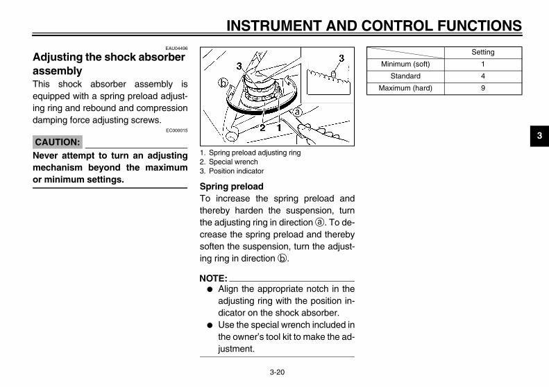
0ESetting
Minimum (soft) 1
Standard 4
Maximum (hard) 9
U5PW10.book Page 20 Thursday, January 10, 2002 12:15 PM
INSTRUMENT AND CO
3-20
EAU04496
djusting the shock absorber sembly is shock absorber assembly isuipped with a spring preload adjust-
g ring and rebound and compressionmping force adjusting screws.
EC000015
AUTION:ever attempt to turn an adjustingechanism beyond the maximum minimum settings.
Spring preloadTo increase the spring preload andthereby harden the suspension, turnthe adjusting ring in direction a. To de-crease the spring preload and therebysoften the suspension, turn the adjust-ing ring in direction b.
NOTE:_
� Align the appropriate notch in theadjusting ring with the position in-dicator on the shock absorber.
� Use the special wrench included inthe owner’s tool kit to make the ad-justment.
_
CI-1
1. Spring preload adjusting ring2. Special wrench3. Position indicator

IN
3
ReTo forcdamrecdamrebscrCI-14
TE:ough the total number of clicks of aping force adjusting mechanism
y not exactly match the above spec-tions due to small differences in
duction, the actual number of clicksays represents the entire adjustingge. To obtain a precise adjustment,ould be advisable to check the num- of clicks of each damping force ad-ing mechanism and to modify thecifications as necessary.
1. R
M
Ma
* Wi
U5PW10.book Page 21 Thursday, January 10, 2002 12:15 PM
STRUMENT AND CONTROL FUNCTIONS
3-21
bound damping forceincrease the rebound damping
e and thereby harden the reboundping, turn the adjusting screw in di-
tion a. To decrease the reboundping force and thereby soften the
ound damping, turn the adjustingew in direction b.E
Compression damping forceTo increase the compression dampingforce and thereby harden the compres-sion damping, turn the adjusting screwin direction a. To decrease the com-pression damping force and therebysoften the compression damping, turnthe adjusting screw in direction b.CI-14E
NO_
Althdammaificaproalwranit wberjustspe_
ebound damping force adjusting screw
inimum (soft) 20 clicks in direction b*
Standard 15 clicks in direction b*
ximum (hard) 1 click in direction b*
th the adjusting screw fully turned in direction a
1. Compression damping force adjusting screw
Minimum (soft) 20 clicks in direction b*
Standard 15 clicks in direction b*
Maximum (hard) 1 click in direction b*
* With the adjusting screw fully turned in direction a

NTROL FUNCTIONS
3
_
ThlyprstfoThsppeim
_
U5PW10.book Page 22 Thursday, January 10, 2002 12:15 PM
INSTRUMENT AND CO
3-22
EAU00315
WARNINGis shock absorber contains high-
pressurized nitrogen gas. Foroper handling, read and under-and the following information be-re handling the shock absorber.e manufacturer cannot be held re-onsible for property damage orrsonal injury that may result fromproper handling.
� Do not tamper with or attempt toopen the gas cylinder.
� Do not subject the shock ab-sorber to an open flame or otherhigh heat sources, otherwise itmay explode due to excessivegas pressure.
� Do not deform or damage thegas cylinder in any way, as thiswill result in poor damping per-formance.
� Always have a Yamaha dealerservice the shock absorber.

IN
3
LuTheon To pasandhanseaseadur
EAU00330
estand sidestand is located on the left sidehe frame. Raise the sidestand orr it with your foot while holding the
orcycle upright.
E: built-in sidestand switch is part ofignition circuit cut-off system, which the ignition in certain situations. further down for an explanation of
ignition circuit cut-off system.)
1. L2. H
U5PW10.book Page 23 Thursday, January 10, 2002 12:15 PM
STRUMENT AND CONTROL FUNCTIONS
3-23
EAU03170
ggage strap holders re are four luggage strap holdersthe bottom of the passenger seat.use the strap holders, remove thesenger seat, unhook the straps, then install the seat with the strapsging out from under the passengert. (See page 3-16 for passengert removal and installation proce-es.)
EAU01571
EXUP system This motorcycle is equipped withYamaha’s EXUP (EXhaust UltimatePower valve) system. This systemboosts engine power by means of avalve that regulates the diameter of theexhaust pipe. The EXUP system valveis constantly adjusted in accordancewith the engine speed by a computer-controlled servomotor.
EC000027
CAUTION:_
� The EXUP system has been setand extensively tested at theYamaha factory. Changingthese settings without sufficienttechnical knowledge may resultin poor performance of or dam-age to the engine.
� If the EXUP system does not op-erate, have a Yamaha dealercheck it.
_
SidTheof tlowemot
NOT_
Thethe cuts(Seethe _
uggage strap holder (× 4)ook (× 4)

NTROL FUNCTIONS
3
_
Thwsimerthtococuasrestchscdepr_
U5PW10.book Page 24 Thursday, January 10, 2002 12:15 PM
INSTRUMENT AND CO
3-24
EW000044
WARNINGe motorcycle must not be ridden
ith the sidestand down, or if thedestand cannot be properlyoved up (or does not stay up), oth-wise the sidestand could contacte ground and distract the opera-r, resulting in a possible loss ofntrol. Yamaha’s ignition circuitt-off system has been designed tosist the operator in fulfilling thesponsibility of raising the side-and before starting off. Therefore,eck this system regularly as de-ribed below and have a Yamahaaler repair it if it does not functionoperly.
EAU03720
Ignition circuit cut-off system The ignition circuit cut-off system (com-prising the sidestand switch, clutchswitch and neutral switch) has the fol-lowing functions.
� It prevents starting when the trans-mission is in gear and the side-stand is up, but the clutch lever isnot pulled.
� It prevents starting when the trans-mission is in gear and the clutchlever is pulled, but the sidestand isstill down.
� It cuts the running engine whenthe transmission is in gear and thesidestand is moved down.
Periodically check the operation of theignition circuit cut-off system accordingto the following procedure.
EW000045
WARNING_
If a malfunction is noted, have aYamaha dealer check the systembefore riding. _
IN
3
CD-0
itch may be defective.le should not be ridden until
Yamaha dealer.
switch may be defective.le should not be ridden until
Yamaha dealer.
itch may be defective.le should not be ridden until
Yamaha dealer.
ost reliable if performed withengine.
U5PW10.book Page 25 Thursday, January 10, 2002 12:15 PM
STRUMENT AND CONTROL FUNCTIONS
3-25
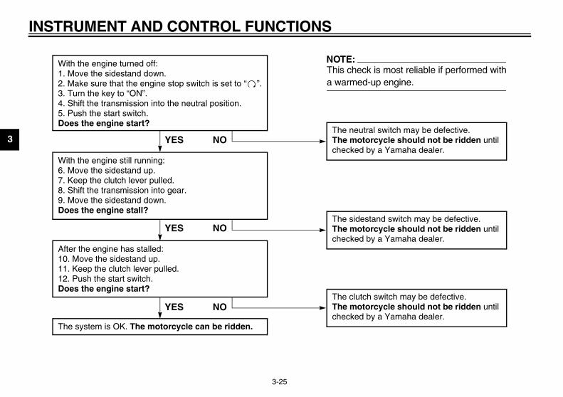
1E
With the engine turned off:1. Move the sidestand down.2. Make sure that the engine stop switch is set to “ ”.3. Turn the key to “ON”. 4. Shift the transmission into the neutral position.5. Push the start switch.Does the engine start?
The neutral swThe motorcycchecked by a
With the engine still running:6. Move the sidestand up.7. Keep the clutch lever pulled.8. Shift the transmission into gear.9. Move the sidestand down.Does the engine stall?
After the engine has stalled:10. Move the sidestand up.11. Keep the clutch lever pulled.12. Push the start switch.Does the engine start?
The sidestandThe motorcycchecked by a
The clutch swThe motorcycchecked by a
NO
NOTE:This check is ma warmed-up
YES
YES NO
The system is OK. The motorcycle can be ridden.
YES NO

PRE-OPERATION CHECKS
4
Pre-operation check list ..................................................................... 4-1
U5PW10.book Page 1 Thursday, January 10, 2002 12:15 PM
4
EAU01114
teriorate quickly and unexpectedly,). Any damage, fluid leakage or lossddition to a thorough visual inspec-
U5PW10.book Page 1 Thursday, January 10, 2002 12:15 PM
4-PR
Theeveof ti
EAU03439
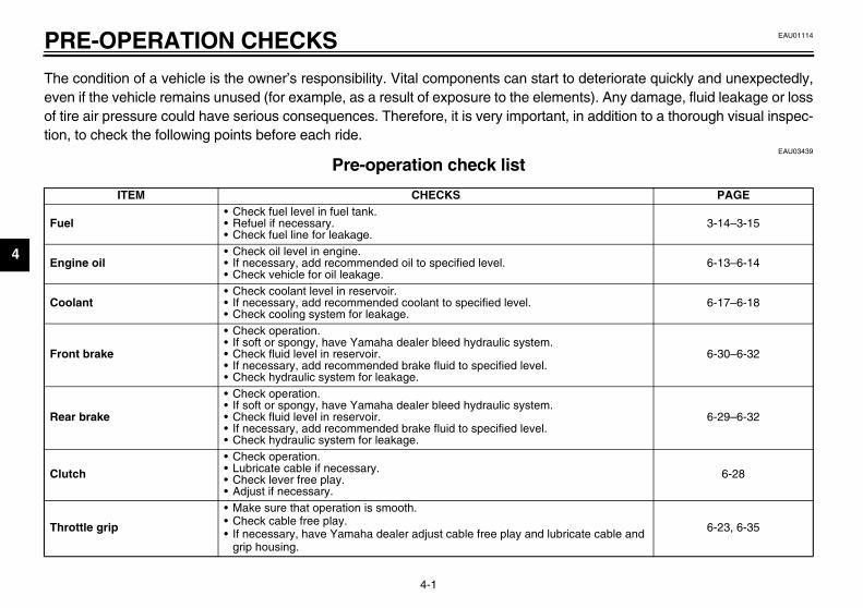
PAGE
3-14–3-15
6-13–6-14
6-17–6-18
6-30–6-32
6-29–6-32
6-28
cable and 6-23, 6-35
tion
CO-01
Fu
En
Co
Fro
Re
Clu
Th
4-1
E-OPERATION CHECKS
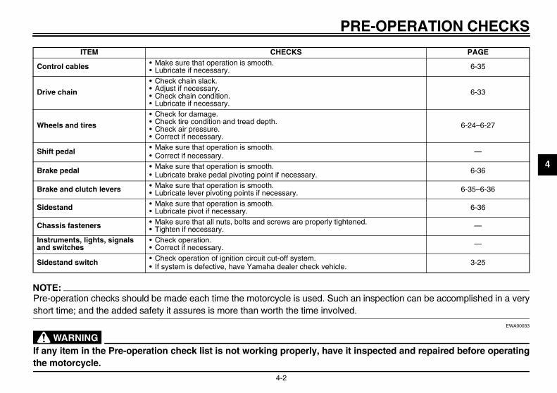
condition of a vehicle is the owner’s responsibility. Vital components can start to den if the vehicle remains unused (for example, as a result of exposure to the elementsre air pressure could have serious consequences. Therefore, it is very important, in a, to check the following points before each ride.
Pre-operation check list E
ITEM CHECKS
el• Check fuel level in fuel tank.• Refuel if necessary.• Check fuel line for leakage.
gine oil• Check oil level in engine.• If necessary, add recommended oil to specified level.• Check vehicle for oil leakage.
olant• Check coolant level in reservoir.• If necessary, add recommended coolant to specified level.• Check cooling system for leakage.
nt brake
• Check operation.• If soft or spongy, have Yamaha dealer bleed hydraulic system.• Check fluid level in reservoir.• If necessary, add recommended brake fluid to specified level.• Check hydraulic system for leakage.
ar brake
• Check operation.• If soft or spongy, have Yamaha dealer bleed hydraulic system.• Check fluid level in reservoir.• If necessary, add recommended brake fluid to specified level.• Check hydraulic system for leakage.
tch
• Check operation.• Lubricate cable if necessary.• Check lever free play.• Adjust if necessary.
rottle grip
• Make sure that operation is smooth.• Check cable free play.• If necessary, have Yamaha dealer adjust cable free play and lubricate
grip housing.
ERATION CHECKS
4
N_
Pr ion can be accomplished in a verysh_
EWA00033
_
If and repaired before operatingth_
C 6-35
D 6-33
W 6-24–6-27
S —
B 6-36
B 6-35–6-36
S 6-36
C —
Ina —
S 3-25
PAGE
U5PW10.book Page 2 Thursday, January 10, 2002 12:15 PM
PRE-OP
4-2
OTE:e-operation checks should be made each time the motorcycle is used. Such an inspectort time; and the added safety it assures is more than worth the time involved.
WARNINGany item in the Pre-operation check list is not working properly, have it inspectede motorcycle.
ontrol cables • Make sure that operation is smooth.• Lubricate if necessary.
rive chain
• Check chain slack.• Adjust if necessary.• Check chain condition.• Lubricate if necessary.
heels and tires
• Check for damage.• Check tire condition and tread depth.• Check air pressure.• Correct if necessary.
hift pedal • Make sure that operation is smooth.• Correct if necessary.
rake pedal • Make sure that operation is smooth.• Lubricate brake pedal pivoting point if necessary.
rake and clutch levers • Make sure that operation is smooth.• Lubricate lever pivoting points if necessary.
idestand • Make sure that operation is smooth.• Lubricate pivot if necessary.
hassis fasteners • Make sure that all nuts, bolts and screws are properly tightened.• Tighten if necessary.
struments, lights, signals nd switches
• Check operation. • Correct if necessary.
idestand switch • Check operation of ignition circuit cut-off system.• If system is defective, have Yamaha dealer check vehicle.
ITEM CHECKS

OPERATION AND IMPORTANT RIDING POINTS
5
Starting and warming up a cold engine ............................................. 5-1Shifting .............................................................................................. 5-3Engine break-in ................................................................................. 5-4Parking .............................................................................................. 5-5
U5PW10.book Page 1 Thursday, January 10, 2002 12:15 PM

5
EAU00372
EAU04568
rting and warming up a ld engine
U5PW10.book Page 1 Thursday, January 10, 2002 12:15 PM
5-OP
_
�
order for the ignition circuit cut-offtem to enable starting, one of thewing conditions must be met:The transmission is in the neutralposition.The transmission is in gear withthe clutch lever pulled and thesidestand up.
EW000054
WARNINGBefore starting the engine,check the function of the igni-tion circuit cut-off system ac-cording to the proceduredescribed on page 3-25. Never ride with the sidestanddown.
Turn the key to “ON” and makesure that the engine stop switch isset to “ ”.
�
�
_
5-1
ERATION AND IMPORTANT RIDING POINTSEAU00373
WARNINGBecome thoroughly familiarwith all operating controls andtheir functions before riding.Consult a Yamaha dealer re-garding any control or functionthat you do not thoroughly un-derstand.Never start the engine or oper-ate it in a closed area for anylength of time. Exhaust fumesare poisonous, and inhalingthem can cause loss of con-sciousness and death within ashort time. Always make surethat there is adequate ventila-tion.Before starting out, make surethat the sidestand is up. If thesidestand is not raised com-pletely, it could contact theground and distract the opera-tor, resulting in a possible lossof control.
EAU00376
CAUTION:_
� Make sure not to store personalitems near the air cleaner in-take, otherwise air intake will beblocked and performance willsuffer.
� Make sure not to put anythingnear the battery and its termi-nals, otherwise electrical failureand acid corrosion may result.
_
StacoIn sysfollo
�
�
_
�
�
_
1.

ANT RIDING POINTS
5
C_
Thdife
If nocoto_
2
N_
WposhYacu_
3
U5PW10.book Page 2 Thursday, January 10, 2002 12:15 PM
OPERATION AND IMPORT
5-2
ECA00132
AUTION:e following warning lights and in-
cator light should come on for aw seconds, then go off.� Oil level warning light� Fuel level warning light� Coolant temperature warning
light� Engine speed indicator light� Engine trouble warning lighta warning or indicator light doest go off, see pages 3-2–3-4 for therresponding warning and indica-r light circuit check.
. Shift the transmission into the neu-tral position.
OTE:hen the transmission is in the neutralsition, the neutral indicator lightould be on, otherwise have amaha dealer check the electrical cir-it.
. Start the engine by pushing thestart switch.
NOTE:_
If the engine fails to start, release thestart switch, wait a few seconds, andthen try again. Each starting attemptshould be as short as possible to pre-serve the battery. Do not crank the en-gine more than 10 seconds on any oneattempt. _
ECA00055
CAUTION:_
For maximum engine life, alwayswarm the engine up before startingoff. Never accelerate hard when theengine is cold! _
NOTE:_
The engine is warm when it quickly re-sponds to the throttle. _

O
5 ShShamstaetcThelus
NO_
To tralreptrav_
EAU02988
start out and accelerate Pull the clutch lever to disengagethe clutch.Shift the transmission into firstgear. The neutral indicator lightshould go out.Open the throttle gradually, and atthe same time, release the clutchlever slowly.At the recommended shift pointsshown in the table on page 5-4,close the throttle, and at the sametime, quickly pull the clutch leverin.Shift the transmission into secondgear. (Make sure not to shift thetransmission into the neutral posi-tion.)Open the throttle part way andgradually release the clutch lever.Follow the same procedure whenshifting to the next higher gear.
TE:ays shift gears at the recommend-shift points.
1. SN. N
U5PW10.book Page 3 Thursday, January 10, 2002 12:15 PM
PERATION AND IMPORTANT RIDING POINTS
5-3
EAU00423
ifting ifting gears lets you control theount of engine power available forrting off, accelerating, climbing hills,. gear positions are shown in the il-
tration.
TE:shift the transmission into the neu- position, press the shift pedal downeatedly until it reaches the end of itsel, and then slightly raise it.
EC000048
CAUTION:_
� Even with the transmission inthe neutral position, do notcoast for long periods of timewith the engine off, and do nottow the motorcycle for long dis-tances. The transmission isproperly lubricated only whenthe engine is running. Inade-quate lubrication may damagethe transmission.
� Always use the clutch whilechanging gears to avoid dam-aging the engine, transmission,and drive train, which are notdesigned to withstand theshock of forced shifting.
_
To 1.
2.
3.
4.
5.
6.
7.
NO_
Alwed _
hift pedaleutral position
ANT RIDING POINTS
5
To1
2
3
EAU01128
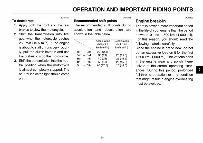
ngine break-in ere is never a more important periodthe life of your engine than the periodtween 0 and 1,600 km (1,000 mi).r this reason, you should read the
llowing material carefully.nce the engine is brand new, do nott an excessive load on it for the first
600 km (1,000 mi). The various partsthe engine wear and polish them-lves to the correct operating clear-ces. During this period, prolonged
ll-throttle operation or any conditionat might result in engine overheatingust be avoided.
U5PW10.book Page 4 Thursday, January 10, 2002 12:15 PM
OPERATION AND IMPORT
5-4
EAU00427
decelerate . Apply both the front and the rear
brakes to slow the motorcycle.. Shift the transmission into first
gear when the motorcycle reaches25 km/h (15.5 mi/h). If the engineis about to stall or runs very rough-ly, pull the clutch lever in and usethe brakes to stop the motorcycle.
. Shift the transmission into the neu-tral position when the motorcycleis almost completely stopped. Theneutral indicator light should comeon.
EAU02989
Recommended shift points The recommended shift points duringacceleration and deceleration areshown in the table below.CF-05E
EThin beFofoSipu1,in seanfuthm
Accelerationshift point
km/h (mi/h)
Decelerationshift point
km/h (mi/h)
1st → 2nd2nd → 3rd3rd → 4th4th → 5th5th → 6th
20 (12.5)30 (19)40 (25)50 (31)
60 (37.5)
—25 (15.5)25 (15.5)25 (15.5)25 (15.5)

O
5
0–1Avo6,0
1,0Avo7,0
CA_
Aftthethe_
1,6Thema
CA_
�
�
_
EAU00461
rking en parking, stop the engine, andn remove the key from the maintch.
EW000058
WARNINGSince the engine and exhaustsystem can become very hot,park in a place where pedestri-ans or children are not likely totouch them. Do not park on a slope or onsoft ground, otherwise themotorcycle may overturn.
EC000062
UTION:er park in an area where there
fire hazards such as grass orer flammable materials.
U5PW10.book Page 5 Thursday, January 10, 2002 12:15 PM
PERATION AND IMPORTANT RIDING POINTS
5-5
EAU03172*
,000 km (0–600 mi)id prolonged operation above
00 r/min.
00–1,600 km (600–1,000 mi)id prolonged operation above
00 r/min.EC000052*
UTION:er 1,000 km (600 mi) of operation, engine oil must be changed and oil filter cartridge replaced.
00 km (1,000 mi) and beyond vehicle can now be operated nor-
lly.EC000053
UTION:Keep the engine speed out ofthe tachometer red zone.If any engine trouble should oc-cur during the engine break-inperiod, immediately have aYamaha dealer check the vehi-cle.
NOTE:_
During and after the engine break-inperiod, the exhaust heat may causediscoloration of the exhaust pipe, butthis is normal. _
PaWhtheswi
_
�
�
_
CA_
Nevareoth_

6
PERIODIC MAINTENANCE AND MINOR REPAIR
Periodic maintenance ..........................................6-1Owner’s tool kit ....................................................6-1Periodic maintenance chart for the emission
control system ...................................................6-3General maintenance and lubrication chart .........6-5Removing and installing cowlings and panels .....6-8Checking the spark plugs ..................................6-11Canister (for California only) ..............................6-13Engine oil and oil filter cartridge ........................6-13Coolant ..............................................................6-17Replacing the air filter element ..........................6-21Adjusting the throttle cable free play ..................6-23Adjusting the valve clearance ............................6-23Tires ...................................................................6-24Cast wheels .......................................................6-27Accessories and replacement parts ..................6-27Adjusting the clutch lever free play ....................6-28Adjusting the brake pedal position .....................6-29Adjusting the rear brake light switch ..................6-29Checking the front and rear brake pads .............6-30Checking the brake fluid level ............................6-31Changing the brake fluid ....................................6-32Drive chain slack ................................................6-33
Lubricating the drive chain ................................ 6-34Checking and lubricating the cables ................. 6-35Checking and lubricating the throttle
grip and cable ................................................. 6-35Checking and lubricating the brake and
clutch levers .................................................... 6-35Lubricating the brake pedal ............................... 6-36Checking and lubricating the sidestand ............ 6-36Checking the front fork ...................................... 6-37Checking the steering ....................................... 6-37Checking the wheel bearings ............................ 6-38Battery ............................................................... 6-39Replacing the fuses .......................................... 6-40Replacing a headlight bulb ................................ 6-41Tail/brake light ................................................... 6-42Replacing a turn signal light bulb ...................... 6-43Replacing the license plate light bulb ................ 6-43Supporting the motorcycle ................................ 6-44Front wheel ....................................................... 6-45Rear wheel ........................................................ 6-47Troubleshooting ................................................. 6-49Troubleshooting charts ...................................... 6-50
U5PW10.book Page 1 Thursday, January 10, 2002 12:15 PM

6
EAU00462
U5PW10.book Page 1 Thursday, January 10, 2002 12:15 PM
6-PE
SafPer
EAU04266
ner’s tool kit owner’s tool kit is located inside
storage compartment under thesenger seat. (See page 3-16 forsenger seat removal and installa- procedures.) service information included in this
nual and the tools provided in theer’s tool kit are intended to assist in the performance of preventiveintenance and minor repairs. How-r, additional tools such as a torquench may be necessary to performtain maintenance work correctly.
wner’s tool kit
bricsafesiblmolubring Maof tsysreptha
_
If ycycYam_
6-1
RIODIC MAINTENANCE AND MINOR REPAIR EAU01790
ety is an obligation of the owner.iodic inspection, adjustment and lu-ation will keep your vehicle in thest and most efficient condition pos-
e. The most important points oftorcycle inspection, adjustment, andication are explained on the follow-pages.intenance, replacement, or repairhe emission control devices andtems may be performed by anyair establishment or individualt is certified (if applicable).
EW000060
WARNINGou are not familiar with motor-le maintenance work, have aaha dealer do it for you.
EAU00467
PERIODIC MAINTENANCE PROPER PERIODIC MAINTENANCEOF YOUR MOTORCYCLE IS IMPOR-TANT IN ORDER TO ENJOY LONG,PLEASURABLE SERVICE. ESPE-CIALLY IMPORTANT ARE THEMAINTENANCE SERVICES RELAT-ED TO EMISSIONS CONTROL.THESE CONTROLS NOT ONLYFUNCTION TO ENSURE CLEANERAIR, BUT ARE ALSO VITAL TOPROPER ENGINE OPERATION ANDMAXIMUM PERFORMANCE. IN THEFOLLOWING PERIODIC MAINTE-NANCE CHARTS, THE SERVICESRELATED TO EMISSIONS CON-TROL ARE GROUPED SEPARATE-LY. THESE SERVICES REQUIRESPECIALIZED DATA, KNOWLEDGE,AND EQUIPMENT. YAMAHA DEAL-ERS ARE TRAINED AND EQUIPPEDTO PERFORM THESE PARTICULARSERVICES.
OwThethepaspastionThemaownyoumaevewrecer
1. O

AND MINOR REPAIR
6
N_
If ena _
_
MYamreCte_
U5PW10.book Page 2 Thursday, January 10, 2002 12:15 PM
PERIODIC MAINTENANCE
6-2
OTE:you do not have the tools or experi-ce required for a particular job, have
Yamaha dealer perform it for you.
EW000062
WARNINGodifications not approved bymaha may cause loss of perfor-
ance, excessive emissions, andnder the vehicle unsafe for use.onsult a Yamaha dealer before at-mpting any changes.

PE
6
EAU00471
ol system
No
OMETER READINGS
im)
hs
12,000 mi(19,000 km)
or18 months
16,000 mi(25,000 km)
or24 months
20,000 mi(31,000 km)
or30 months
1 00 mi (42,000 km)
2 e. √ Replace. √
3 √ √ √
4 √ √ √
5 √ √ √
6 √ √ √
U5PW10.book Page 3 Thursday, January 10, 2002 12:15 PM
RIODIC MAINTENANCE AND MINOR REPAIR
6-3
Periodic maintenance chart for the emission contr
. ITEM ROUTINE
INITIAL OD
600 mi(1,000 km)
or1 month
4,000mi(7,000 km)
or6 months
8,000 m(13,000 k
or12 mont
* Valve clearance • Check and adjust valve clearance when engine is cold. Every 26,6
* Spark plugs
• Check condition. • Adjust gap and clean. • Replace every 8,000 mi (13,000 km) or
12 months.
√ Replac
*Crankcase ventilation system
• Check ventilation hose for cracks or damage.
• Replace if necessary.√ √
* Fuel line• Check fuel hoses and vacuum hose
for cracks or damage.• Replace if necessary.
√ √
* Exhaust system• Check for leakage. • Retighten if necessary. • Replace gasket(s) if necessary.
√ √
*Electronic fuel injection
• Check and adjust engine idle speed and synchronization. √ √ √

AND MINOR REPAIR
6
* S e.
7 √ √
8 √ √ √
N
OMETER READINGS
im)
hs
12,000 mi(19,000 km)
or18 months
16,000 mi(25,000 km)
or24 months
20,000 mi(31,000 km)
or30 months
U5PW10.book Page 4 Thursday, January 10, 2002 12:15 PM
PERIODIC MAINTENANCE
6-4
ince these items require special tools, data and technical skills, have a Yamaha dealer perform the servic
*
Evaporative emission control system (for California only)
• Check control system for damage.• Replace if necessary.
*Air induction system
• Check the air cut-off valve, reed valve, and hose for damage.
• Replace any damaged parts if necessary.
√ √
o. ITEM ROUTINE
INITIAL OD
600 mi(1,000 km)
or1 month
4,000mi(7,000 km)
or6 months
8,000 m(13,000 k
or12 mont
PE
6
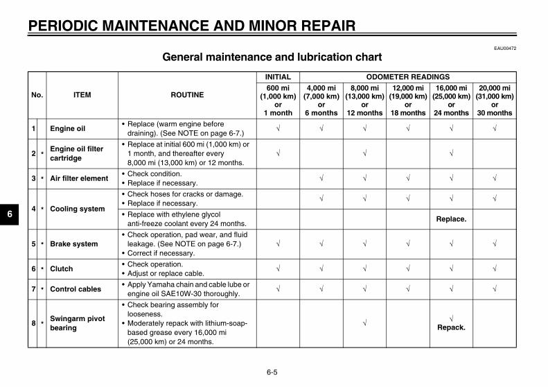
EAU00472
rt
No
OMETER READINGS
im)
hs
12,000 mi(19,000 km)
or18 months
16,000 mi(25,000 km)
or24 months
20,000 mi(31,000 km)
or30 months
1 √ √ √
2 √
3 √ √ √
4√ √ √
Replace.
5 √ √ √
6 √ √ √
7 √ √ √
8 √Repack.
U5PW10.book Page 5 Thursday, January 10, 2002 12:15 PM
RIODIC MAINTENANCE AND MINOR REPAIR
6-5
General maintenance and lubrication cha
. ITEM ROUTINE
INITIAL OD
600 mi (1,000 km)
or1 month
4,000 mi(7,000 km)
or6 months
8,000 m(13,000 k
or12 mont
Engine oil• Replace (warm engine before
draining). (See NOTE on page 6-7.)√ √ √
*Engine oil filter cartridge
• Replace at initial 600 mi (1,000 km) or 1 month, and thereafter every 8,000 mi (13,000 km) or 12 months.
√ √
* Air filter element• Check condition.• Replace if necessary.
√ √
* Cooling system
• Check hoses for cracks or damage.• Replace if necessary.
√ √
• Replace with ethylene glycol anti-freeze coolant every 24 months.
* Brake system• Check operation, pad wear, and fluid
leakage. (See NOTE on page 6-7.)• Correct if necessary.
√ √ √
* Clutch• Check operation.• Adjust or replace cable.
√ √ √
* Control cables• Apply Yamaha chain and cable lube or
engine oil SAE10W-30 thoroughly.√ √ √
*Swingarm pivot bearing
• Check bearing assembly for looseness.
• Moderately repack with lithium-soap-based grease every 16,000 mi (25,000 km) or 24 months.
√

AND MINOR REPAIR
6
9 √
10 √ √ √
11 √ √ √
12 √ √Repack. √
13 √ √ √
14 √ √ √
15) or after washing the motorcycle ing in the rain.
16 √ √ √
17 √ √ √
18 √ √ √
N
DOMETER READINGS
mi km)
ths
12,000 mi(19,000 km)
or18 months
16,000 mi(25,000 km)
or24 months
20,000 mi(31,000 km)
or30 months
U5PW10.book Page 6 Thursday, January 10, 2002 12:15 PM
PERIODIC MAINTENANCE
6-6
*Rear suspension link pivots
• Check operation.• Correct if necessary.
√
*Shock absorber assembly
• Check operation and for oil leakage.• Replace if necessary.
√ √
* Front fork• Check operation and for oil leakage.• Repair if necessary.
√ √
* Steering bearings
• Check bearing assembly for looseness.
• Moderately repack with lithium-soap-based grease every 16,000 mi (25,000 km) or 24 months.
√ √
Brake and clutch lever pivot shafts
• Apply chain lube or lithium-soap-based grease lightly.
√ √ √
Brake pedal • Apply chain lube or lithium-soap-
based grease lightly.√ √
* Drive chain
• Check chain slack/alignment condition.
• Adjust and lubricate chain with Yamaha chain and cable lube or engine oil SAE10W-30 thoroughly.
Every 600 mi (1,000 kmor rid
* Wheel bearings • Check bearings for smooth operation. √ √
* Sidestand pivot• Check operation.• Apply chain lube or lithium-soap-
based grease lightly.√ √
* Sidestand switch• Check and clean or replace if
necessary.√ √ √
o. ITEM ROUTINE
INITIAL O
600 mi (1,000 km)
or1 month
4,000 mi(7,000 km)
or6 months
8,000 (13,000
or12 mon

PE
6
* Si . EAU03907
NO_
Fro m 4,000 mi (7,000 km) or 6 months. _
EAU04573
NO_
�
hich must not be cleaned with com-
ally wet or dusty areas.�
luid. Regularly check the brake fluid
and calipers, and change the brake
�
°C (40 °F) or above.5 °C (60 °F) or below.
_
19 √ √ √
No
OMETER READINGS
im)
hs
12,000 mi(19,000 km)
or18 months
16,000 mi(25,000 km)
or24 months
20,000 mi(31,000 km)
or30 months
U5PW10.book Page 7 Thursday, January 10, 2002 12:15 PM
RIODIC MAINTENANCE AND MINOR REPAIR
6-7
nce these items require special tools, data and technical skills, have a Yamaha dealer perform the service
TE:m 24,000 mi (37,000 km) or 36 months, repeat the maintenance intervals starting fro
TE:Air filter• This model’s air filter is equipped with a disposable oil-coated paper element, w
pressed air to avoid damaging it.• The air filter element needs to be replaced more frequently when riding in unusuHydraulic brake service• After disassembling the brake master cylinders and calipers, always change the f
levels and fill the reservoirs as required.• Every two years replace the internal components of the brake master cylinders
fluid.• Replace the brake hoses every four years and if cracked or damaged.Engine oil type• Yamalube 4 (20W-40) or engine oil SAE 20W-40 (API SE) for temperatures of 5• Yamalube 4 (10W-30) or engine oil SAE 10W-30 (API SE) for temperatures of 1
* Chassis fasteners• Check all chassis fittings and
fasteners.• Correct if necessary.
√ √
. ITEM ROUTINE
INITIAL OD
600 mi (1,000 km)
or1 month
4,000 mi(7,000 km)
or6 months
8,000 m(13,000 k
or12 mont

AND MINOR REPAIR
6
RcoThneofthtimm
1.2.3.
U5PW10.book Page 8 Thursday, January 10, 2002 12:15 PM
PERIODIC MAINTENANCE
6-8
EAU01139
emoving and installing wlings and panels e cowlings and panels shown aboveed to be removed to perform some
the maintenance jobs described inis chapter. Refer to this section eache a cowling or panel needs to be re-
oved and installed.
Panel ACowling ACowling B
1. Panel B2. Cowling B

PE
6
CoTo
1.
Disconnect the turn signal lightlead coupler.Remove the screws, and then takethe cowling off.
install the cowlingInstall the screws.Connect the turn signal light leadcoupler.Place the cowling in the originalposition.Install the screw and the bolts,tighten the quick fastener screws,and then install the quick fasten-ers.
1. Q urn signal light lead couplercrew (× 2)
U5PW10.book Page 9 Thursday, January 10, 2002 12:15 PM
RIODIC MAINTENANCE AND MINOR REPAIR
6-9
EAU04544
wling Aremove the cowling
Remove the quick fasteners at thefront of the cowling.
2. Remove the bolts and screw, andthen loosen the quick fastenerscrews 1/4 turn counterclockwise.
3. Slide the cowling backward at thearea shown.
4.
5.
To 1.2.
3.
4.
uick fastener (× 4) 1. Quick fastener screw (× 6)2. Screw3. Bolt (× 2)
1. T2. S
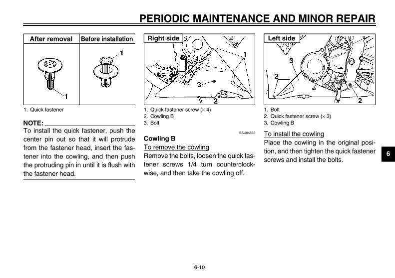
AND MINOR REPAIR
6
N_
Tocefrotethth_
install the cowlingce the cowling in the original posi-, and then tighten the quick fastenerews and install the bolts.
1. oltuick fastener screw (× 3)owling B
ft side
U5PW10.book Page 10 Thursday, January 10, 2002 12:15 PM
PERIODIC MAINTENANCE
6-10
OTE: install the quick fastener, push thenter pin out so that it will protrudem the fastener head, insert the fas-
ner into the cowling, and then pushe protruding pin in until it is flush withe fastener head.
EAU04555
Cowling BTo remove the cowlingRemove the bolts, loosen the quick fas-tener screws 1/4 turn counterclock-wise, and then take the cowling off.
To Plationscr
Quick fastener
After removal Before installation
1. Quick fastener screw (× 4)2. Cowling B3. Bolt
Right side
1. B2. Q3. C
Le

PE
6
PaTo Looturnscr
To Platighthe
1. Q2. S
pecified spark plug:CR9EIA 9 (NGK) or IU27D (DENSO)
U5PW10.book Page 11 Thursday, January 10, 2002 12:15 PM
RIODIC MAINTENANCE AND MINOR REPAIR
6-11
EAU04531
nels A and Bremove one of the panelssen the quick fastener screws 1/4 counterclockwise, remove the
ew, and then take the panel off.
install the panelce the panel in the original position,ten the quick fastener screws, andn install the screw.
EAU01880
Checking the spark plugs The spark plugs are important enginecomponents, which should be checkedperiodically, preferably by a Yamahadealer. Since heat and deposits willcause any spark plug to slowly erode,they should be removed and checkedin accordance with the periodic mainte-nance and lubrication chart. In addition,the condition of the spark plugs can re-veal the condition of the engine.The porcelain insulator around the cen-ter electrode of each spark plug shouldbe a medium-to-light tan (the ideal col-or when the motorcycle is ridden nor-mally), and all spark plugs installed inthe engine should have the same color.If any spark plug shows a distinctly dif-ferent color, the engine could be defec-tive. Do not attempt to diagnose suchproblems yourself. Instead, have aYamaha dealer check the motorcycle.If a spark plug shows signs of electrodeerosion and excessive carbon or otherdeposits, it should be replaced.
uick fastener screw (× 2)crew
S

ND MINOR REPAIR
6
Beplwad
a.
U5PW10.book Page 12 Thursday, January 10, 2002 12:15 PM
PERIODIC MAINTENANCE A
6-12
fore installing a spark plug, the sparkug gap should be measured with aire thickness gauge and, if necessary,justed to specification.
Clean the surface of the spark pluggasket and its mating surface, and thenwipe off any grime from the spark plugthreads.
NOTE:_
If a torque wrench is not available wheninstalling a spark plug, a good estimateof the correct torque is 1/4–1/2 turnpast finger tight. However, the sparkplug should be tightened to the speci-fied torque as soon as possible. _
Spark plug gap
Spark plug gap:0.8–0.9 mm (0.03–0.04 in)
Tightening torque:Spark plug:
12.5 Nm (1.25 m·kgf, 9.0 ft·lbf)

PE
6
CaThito pintothisthe
�
�
EAU04279
ine oil and oil filter tridge engine oil level should be checkedre each ride. In addition, the oilt be changed and the oil filter car-e replaced at the intervals speci-in the periodic maintenance andcation chart.
heck the engine oil levelPlace the motorcycle on a levelsurface and hold it in an uprightposition.
E:e sure that the motorcycle is posi-d straight up when checking the oil
l. A slight tilt to the side can result inse reading.
U5PW10.book Page 13 Thursday, January 10, 2002 12:15 PM
RIODIC MAINTENANCE AND MINOR REPAIR
6-13
EAU00499
nister (for California only) s model is equipped with a canisterrevent the discharging of fuel vapor the atmosphere. Before operating motorcycle, make sure to check following:
Check each hose connection.Check each hose and canister forcracks or damage. Replace ifdamaged.
� Make sure that the canisterbreather is not blocked, and if nec-essary, clean it.
EngcarThe befomustridgfied lubri
To c1.
NOT_
Maktionelevea fal_

ND MINOR REPAIR
6
2
3
N_
Thm_
4
emove the engine oil filler capnd drain bolt to drain the oil fromhe crankcase.
:teps 5–7 if the oil filter cartridge ising replaced.
1.2.3.4.
ine oil drain bolt
U5PW10.book Page 14 Thursday, January 10, 2002 12:15 PM
PERIODIC MAINTENANCE A
6-14
. Start the engine, warm it up forseveral minutes, and then turn it off.
. Wait a few minutes until the oil set-tles, and then check the oil levelthrough the check window locatedat the bottom-right side of thecrankcase.
OTE:e engine oil should be between the
inimum and maximum level marks.
. If the engine oil is below the mini-mum level mark, add sufficient oilof the recommended type to raiseit to the correct level.
To change the engine oil (with orwithout oil filter cartridge replace-ment)
1. Remove cowling B. (See page 6-10for cowling removal and installationprocedures.)
2. Start the engine, warm it up forseveral minutes, and then turn itoff.
3. Place an oil pan under the engineto collect the used oil. 4. R
at
NOTE_
Skip snot be_
Engine oil level check windowMaximum level markMinimum level markEngine oil filler cap
1. Eng

PE
6
5.
NO_
AnYa_
Install the new oil filter cartridge,and then tighten it to the specifiedtorque with a torque wrench.
Install the engine oil drain bolt, andthen tighten it to the specifiedtorque.
1. O2. O
orque wrench
ightening torque:Oil filter cartridge:
17 Nm (1.7 m·kgf, 12 ft·lbf)
ightening torque:Engine oil drain bolt:
43 Nm (4.3 m·kgf, 31 ft·lbf)
U5PW10.book Page 15 Thursday, January 10, 2002 12:15 PM
RIODIC MAINTENANCE AND MINOR REPAIR
6-15
Remove the oil filter cartridge withan oil filter wrench.
TE: oil filter wrench is available at amaha dealer.
6. Apply a thin coat of engine oil tothe O-ring of the new oil filter car-tridge.
NOTE:_
Make sure that the O-ring is properlyseated. _
7.
8.
il filter wrenchil filter cartridge
1. O-ring 1. T
T
T

ND MINOR REPAIR
6
9
C_
_
U5PW10.book Page 16 Thursday, January 10, 2002 12:15 PM
PERIODIC MAINTENANCE A
6-16
. Add the specified amount of therecommended engine oil, and theninstall and tighten the oil filler cap.
ECA00105
AUTION:� In order to prevent clutch slip-
page (since the engine oil alsolubricates the clutch), do notmix any chemical additives withthe oil or use oils of grade “CD”or higher. In addition, do notuse oils labeled “ENERGYCONSERVING II” or higher.
� Make sure that no foreign mate-rial enters the crankcase.
10. Start the engine, and then let it idlefor several minutes while checkingit for oil leakage. If oil is leaking,immediately turn the engine offand check for the cause.
NOTE:_
After the engine is started, the engineoil level warning light should go off if theoil level is sufficient. _
EC000067
CAUTION:_
If the oil level warning light flickersor remains on, immediately turn theengine off and have a Yamaha deal-er check the vehicle. _
11. Turn the engine off, and thencheck the oil level and correct it ifnecessary.
12. Install the cowling.
Recommended engine oil:See page 8-1.
Oil quantity:Without oil filter cartridge replacement:
2.9 L (2.55 lmp qt, 3.07 US qt)With oil filter cartridge replacement:
3.1 L (2.73 lmp qt, 3.28 US qt)Total amount (dry engine):
3.8 L (3.34 lmp qt, 4.02 US qt)

PE
6
CoThebefantspeand
To1.
EC000080
UTION:If coolant is not available, usedistilled water or soft tap waterinstead. Do not use hard wateror salt water since it is harmfulto the engine. If water has been used insteadof coolant, replace it with cool-ant as soon as possible, other-wise the engine may not besufficiently cooled and the cool-ing system will not be protectedagainst frost and corrosion. If water has been added to thecoolant, have a Yamaha dealercheck the antifreeze content ofthe coolant as soon as possible,otherwise the effectiveness ofthe coolant will be reduced.
EW000067
WARNINGer attempt to remove the radia-
cap when the engine is hot.
1. M2. M
U5PW10.book Page 17 Thursday, January 10, 2002 12:15 PM
RIODIC MAINTENANCE AND MINOR REPAIR
6-17
EAU04298
olant coolant level should be checked
ore each ride. In addition, the cool- must be changed at the intervalscified in the periodic maintenance lubrication chart.
check the coolant level Place the motorcycle on a levelsurface and hold it in an uprightposition.
NOTE:_
� The coolant level must be checkedon a cold engine since the levelvaries with engine temperature.
� Make sure that the motorcycle ispositioned straight up whenchecking the coolant level. A slighttilt to the side can result in a falsereading.
_
2. Check the coolant level in thecoolant reservoir.
NOTE:_
The coolant should be between theminimum and maximum level marks. _
3. If the coolant is at or below the min-imum level mark, remove panel A(See page 6-11 for panel removaland installation procedures.), re-move the reservoir cap, add cool-ant to the maximum level mark,and then install the reservoir capand the panel.
CA_
�
�
�
_
_
Nevtor_
aximum level markinimum level mark
Coolant reservoir capacity:0.24 L (0.21 Imp qt, 0.25 US qt)

ND MINOR REPAIR
6
N_
_
emove the clutch cable holderrom the coolant reservoir ashown.emove the coolant reservoir by
emoving the bolts, and then turnhe coolant reservoir upside downo empty it.nstall the coolant reservoir by in-talling the bolts, and then installhe clutch cable holder.
(× 2)lant reservoir
tch cable holder
U5PW10.book Page 18 Thursday, January 10, 2002 12:15 PM
PERIODIC MAINTENANCE A
6-18
OTE:� The radiator fan is automatically
switched on or off according to thecoolant temperature in the radia-tor.
� If the engine overheats, see page6-51 for further instructions.
EAU04524
To change the coolant 1. Place the motorcycle on a level
surface and let the engine cool ifnecessary.
2. Remove cowlings A and B, andpanel A. (See pages 6-9–6-11 forcowling and panel removal and in-stallation procedures.)
3. Place a container under the en-gine to collect the used coolant.
4. Remove the radiator cap and cool-ant reservoir cap.
EW000067
WARNING_
Never attempt to remove the radia-tor cap when the engine is hot. __
5. Rfs
6. Rrtt
7. Ist
1. Coolant reservoir cap2. Radiator cap
1. Bolt2. Coo3. Clu

PE
6
8.
9.
Pour the specified amount of rec-ommended coolant into the radia-tor and reservoir.
1. C2. C
ntifreeze/water mixture ratio:1:1
ecommended antifreeze:High-quality ethylene glycol antifreeze containing corrosioninhibitors for aluminum engines
oolant quantity:Total amount:
2.45 L (2.16 lmp qt, 2.59 US qt)Coolant reservoir capacity:
0.24 L (0.21 lmp qt, 0.25 US qt)
U5PW10.book Page 19 Thursday, January 10, 2002 12:15 PM
RIODIC MAINTENANCE AND MINOR REPAIR
6-19
Remove the coolant drain bolt todrain the cooling system.Loosen the radiator hose clampscrew located at the left side of theengine, and then pull off the hoseto drain the radiator.
10. After the coolant is completelydrained, thoroughly flush the cool-ing system with clean tap water.
11. Install the coolant drain bolt, andthen tighten it to the specifiedtorque.
NOTE:_
Check the washer for damage and re-place it if necessary. _
12. Connect the radiator hose, andthen tighten the clamp screw.
13.
oolant drain boltlamp screw
Tightening torque:Coolant drain bolt:
10 Nm (1.0 m·kgf, 7.2 ft·lbf)
A
R
C

AND MINOR REPAIR
6
C_
_
U5PW10.book Page 20 Thursday, January 10, 2002 12:15 PM
PERIODIC MAINTENANCE
6-20
EC000080
AUTION:� If coolant is not available, use
distilled water or soft tap waterinstead. Do not use hard wateror salt water since it is harmfulto the engine.
� If water has been used insteadof coolant, replace it with cool-ant as soon as possible, other-wise the engine may not besufficiently cooled and the cool-ing system will not be protectedagainst frost and corrosion.
� If water has been added to thecoolant, have a Yamaha dealercheck the antifreeze content ofthe coolant as soon as possible,otherwise the effectiveness ofthe coolant will be reduced.
14. Install the radiator cap and thecoolant reservoir cap, and thenstart the engine and let it idle forseveral minutes. During this peri-od, rev the engine two or threetimes between 3,000–5,000 r/min,and then turn it off.
15. Remove the radiator cap to checkthe coolant level in the radiator. Ifnecessary, add sufficient coolantuntil it reaches the top of the radia-tor, and then install the radiatorcap.
16. Check the coolant level in the res-ervoir. If necessary, remove thecoolant reservoir cap, add coolantto the maximum level mark, andthen install the cap.
17. Start the engine, and then checkthe vehicle for coolant leakage. Ifcoolant is leaking, have a Yamahadealer check the cooling system.
18. Install the cowlings and the panel.

PE
6
ReeleTheplaperchamousu
1.
2.
Remove the air filter case cover byremoving the screws and bolt.
1. B oltcrew (× 8)ir filter case cover
U5PW10.book Page 21 Thursday, January 10, 2002 12:15 PM
RIODIC MAINTENANCE AND MINOR REPAIR
6-21
EAU04572*
placing the air filter ment air filter element should be re-
ced at the intervals specified in theiodic maintenance and lubricationrt. Replace the air filter elementre frequently if you are riding in un-ally wet or dusty areas.Remove the rider seat. (See page3-15 for rider seat removal and in-stallation procedures.)Remove the bolt.
3. Lift the front of the fuel tank, andthen tilt it back and away from theair filter case. (Do not disconnectthe fuel hoses!)
EW000071
WARNING_
� Make sure that the fuel tank iswell supported.
� Do not tilt or pull the fuel tanktoo much, otherwise the fuelhoses may come loose, whichcould cause fuel leakage.
_
4. Disconnect the fuel tank breatherhose and the fuel tank overflowhose.
5.
olt 1. Fuel tank breather hose2. Fuel tank overflow hose
1. B2. S3. A

ND MINOR REPAIR
6
67 onnect the fuel tank breather
ose and the fuel tank overflowose, place the fuel tank in theriginal position, and then installe bolt.
1. tank breather hose tank overflow hose
U5PW10.book Page 22 Thursday, January 10, 2002 12:15 PM
PERIODIC MAINTENANCE A
6-22
. Pull the air filter element out.
. Insert a new air filter element intothe air filter case.
EC000082*
CAUTION:_
� Make sure that the air filter ele-ment is properly seated in theair filter case.
� The engine should never be op-erated without the air filter ele-ment installed, otherwise thepistons and/or cylinders maybecome excessively worn.
_
8. Install the air filter case cover byinstalling the screws and bolt.
9. Chhoth
Air filter element 1. Fuel2. Fuel

PE
6
_
�
�
�
_
10.
EAU00637
usting the valve clearance valve clearance changes with use,lting in improper air-fuel mixtureor engine noise. To prevent this occurring, the valve clearancet be adjusted by a Yamaha dealere intervals specified in the periodictenance and lubrication chart.
1. F2. F
U5PW10.book Page 23 Thursday, January 10, 2002 12:15 PM
RIODIC MAINTENANCE AND MINOR REPAIR
6-23
EWA00067
WARNINGBefore installing the fuel tank,make sure that the fuel hosesare not damaged. If any fuelhose is damaged, do not startthe engine but have a Yamahadealer replace the hose, other-wise fuel may leak.Make sure that the fuel hosesare properly connected androuted, and not pinched.Be sure to place the fuel tankbreather hose and the fuel tankoverflow hose in the original po-sition.
Install the rider seat.
EAU00635
Adjusting the throttle cable free play The throttle cable free play shouldmeasure 3–5 mm (0.1–0.2 in) at thethrottle grip. Periodically check thethrottle cable free play and, if neces-sary, have a Yamaha dealer adjust it.
AdjThe resuand/frommusat thmain
uel tank breather hoseuel tank overflow hose
a. Throttle cable free play

AND MINOR REPAIR
6
TToitycyre
TiThchbe
_
_
ndition and pressure of your tires.VER OVERLOAD YOUR MOTOR-CLE. Make sure that the total
eight of the cargo, rider, passen-r, and accessories (cowling, sad-
ebags, etc. if approved for thisodel) does not exceed the maxi-um load of the motorcycle. Opera-n of an overloaded motorcycleuld cause tire damage, an acci-nt, or even injury.
U5PW10.book Page 24 Thursday, January 10, 2002 12:15 PM
PERIODIC MAINTENANCE
6-24
EAU03581
ires maximize the performance, durabil-, and safe operation of your motor-cle, note the following pointsgarding the specified tires.
re air pressuree tire air pressure should beecked and, if necessary, adjustedfore each ride.
EW000082
WARNING� The tire air pressure must be
checked and adjusted on coldtires (i.e., when the temperatureof the tires equals the ambienttemperature).
� The tire air pressure must beadjusted in accordance with theriding speed and with the totalweight of rider, passenger, car-go, and accessories approvedfor this model.
CE-22E
CE-16E
EW000083
WARNING_
Proper loading of your motorcycleis important for several characteris-tics of your motorcycle, such ashandling, braking, performance andsafety. Do not carry loosely packeditems that can shift. Securely packyour heaviest items close to thecenter of the motorcycle, and dis-tribute the weight evenly from sideto side. Properly adjust the suspen-sion for your load, and check the
coNECYwgedlmmtiocode_
Tire air pressure(measured on cold tires)
Load* Front Rear
Up to 90 kg (198 lb)250 kPa(2.50 kgf/cm2,36 psi)
250 kPa(2.50 kgf/cm2,36 psi)
90 kg (198 lb)–maximum
250 kPa(2.50 kgf/cm2,36 psi)
290 kPa(2.90 kgf/cm2,42 psi)
High-speed riding250 kPa(2.50 kgf/cm2,36 psi)
250 kPa(2.50 kgf/cm2,36 psi)
Maximum load*YZF-R1: 202 kg (445 lb)YZF-R1C: 201 kg (443 lb)
* Total weight of rider, passenger, cargo and accessories

PE
6
TirAlwthecroif thin itachavCE-09
informations motorcycle is equipped with castels and tubeless tires with valves.
1. S2. Ta. T
M(fr
ire air valveire air valve coreire air valve cap with seal
U5PW10.book Page 25 Thursday, January 10, 2002 12:15 PM
RIODIC MAINTENANCE AND MINOR REPAIR
6-25
e inspectionays check the tires before operating motorcycle. If a tire tread showssswise lines (minimum tread depth),e tire has a nail or glass fragments
t, or if the sidewall is cracked, con-t a Yamaha dealer immediately ande the tire replaced.
E
EW000094
WARNING_
� It is dangerous to ride with aworn-out tire. When a tire treadbegins to show crosswise lines,have a Yamaha dealer replacethe tire immediately.
� The replacement of all wheel-and brake-related parts, includ-ing the tires, should be left to aYamaha dealer, who has thenecessary professional knowl-edge and experience.
_
TireThiwhe
idewallire wear indicatorire tread depth
inimum tire tread depth ont and rear)
1.0 mm (0.04 in)
1. T2. T3. T

AND MINOR REPAIR
6
_
_
EAU00684
WARNINGis motorcycle is fitted with super-
gh-speed tires. Note the followingints in order to make the most ef-ient use of these tires.
� Use only the specified replace-ment tires. Other tires may runthe danger of bursting at superhigh speeds.
� Brand-new tires can have a rela-tively poor grip on certain roadsurfaces until they have been“broken in”. Therefore, it is ad-visable before doing any high-speed riding to ride conserva-tively for approximately 100 km(60 mi) after installing a newtire.
� The tires must be warmed upbefore a high-speed run.
� Always adjust the tire air pres-sure according to the operatingconditions.
U5PW10.book Page 26 Thursday, January 10, 2002 12:15 PM
PERIODIC MAINTENANCE
6-26
EW000080
WARNING� The front and rear tires should
be of the same make and de-sign, otherwise the handlingcharacteristics of the motor-cycle cannot be guaranteed.
� After extensive tests, only thetires listed below have been ap-proved for this model byYamaha Motor Co., Ltd.
� Always make sure that the valvecaps are securely installed toprevent air pressure leakage.
� Use only the tire valves andvalve cores listed below toavoid tire deflation during ahigh-speed ride.
CE-10E
CE-14E
_
Thhipofic
_
FRONT
Manufacturer Size Model
Michelin120/70 ZR17 M/C (58W)
Pilot SPORT E120/70 ZR17 (58W)
Dunlop 120/70 ZR17 M/C (58W) D208FL
REAR
Manufacturer Size Model
Michelin190/50 ZR17 M/C (73W)
Pilot SPORT190/50 ZR17 (73W)
Dunlop 190/50 ZR17 M/C (73W) D208L
FRONT & REAR
Tire air valve TR412
Valve core #9000A (original)

PE
6
CaTo ity,cycreg
�
�
�
the use of items which have notn approved by Yamaha.
U5PW10.book Page 27 Thursday, January 10, 2002 12:15 PM
RIODIC MAINTENANCE AND MINOR REPAIR
6-27
EAU03773
st wheels maximize the performance, durabil- and safe operation of your motor-le, note the following pointsarding the specified wheels.
The wheel rims should be checkedfor cracks, bends or warpage be-fore each ride. If any damage isfound, have a Yamaha dealer re-place the wheel. Do not attempteven the smallest repair to thewheel. A deformed or crackedwheel must be replaced.The wheel should be balancedwhenever either the tire or wheelhas been changed or replaced. Anunbalanced wheel can result inpoor performance, adverse han-dling characteristics, and a short-ened tire life.Ride at moderate speeds afterchanging a tire since the tire sur-face must first be “broken in” for itto develop its optimal characteris-tics.
EAU00691
Accessories and replacement parts
EW000098
WARNING_
This motorcycle is not designed topull a trailer or to be attached to asidecar. The accessories or replace-ment parts you choose for yourmotorcycle should be designed spe-cifically for this model, and theymust be securely mounted to main-tain the inherent stability of the orig-inal design. Genuine Yamaha Partsand Accessories are designed andtested to be compatible with yourmotorcycle. Please consider Genu-ine Yamaha Parts and Accessoriesbefore making a purchase. Use ofnon-Yamaha-approved accessoriesor replacement parts may causeloss of handling stability and ridingsafety. Since Yamaha cannot con-trol the quality of accessories orparts manufactured by other com-panies, Yamaha cannot be held lia-ble for any consequences caused
by bee_

AND MINOR REPAIR
6
ApThsuPeplloTotuveclbo
. Remove cowling B. (See page 6-10for cowling removal and installationprocedures.)
. Loosen the locknut at the crank-case.
. To increase the clutch lever freeplay, turn the adjusting nut in di-rection a. To decrease the clutchlever free play, turn the adjustingnut in direction b.
. Tighten the locknut.
. Install the cowling.
1.c.
LocknutClutch lever free play adjusting nut (crankcase)
U5PW10.book Page 28 Thursday, January 10, 2002 12:15 PM
PERIODIC MAINTENANCE
6-28
EAU01356
djusting the clutch lever free lay e clutch lever free play should mea-re 10–15 mm (0.4–0.6 in) as shown.riodically check the clutch lever free
ay and, if necessary, adjust it as fol-ws. increase the clutch lever free play,
rn the adjusting bolt at the clutch le-r in direction a. To decrease the
utch lever free play, turn the adjustinglt in direction b.
NOTE:_
If the specified clutch lever free playcannot be obtained as describedabove, proceed as follows. _
1. Fully turn the adjusting bolt at theclutch lever in direction a to loos-en the clutch cable.
2
3
4
56
Clutch lever free play adjusting boltClutch lever free play
1.2.

PE
6
AdpoThepos(1.5foochenecjus
EAU00713
ting the rear brake light h ar brake light switch, which is ac- by the brake pedal, is properlyd when the brake light comes
t before braking takes effect. Ifary, adjust the brake light switchws.e adjusting nut while holding therake light switch in place. Tothe brake light come on earlier,e adjusting nut in direction a. Tothe brake light come on later,e adjusting nut in direction b.
a. Db
brake light switch brake light switch adjusting nut
U5PW10.book Page 29 Thursday, January 10, 2002 12:15 PM
RIODIC MAINTENANCE AND MINOR REPAIR
6-29
EAU01357
justing the brake pedal sition top of the brake pedal should beitioned approximately 38–42 mm–1.7 in) below the bottom of the
trest bracket as shown. Periodicallyck the brake pedal position and, ifessary, have a Yamaha dealer ad-
t it.
EW000109
WARNING_
A soft or spongy feeling in the brakepedal can indicate the presence ofair in the hydraulic system. If thereis air in the hydraulic system, have aYamaha dealer bleed the system be-fore operating the motorcycle. Air inthe hydraulic system will diminishthe braking performance, whichmay result in loss of control and anaccident. _
AdjusswitcThe retivatedadjusteon jusnecessas folloTurn threar bmake turn thmake turn th
istance between brake pedal and footrest racket
1. Rear2. Rear

AND MINOR REPAIR
6
CbThchifilu
EAU04396
ar brake padsch rear brake pad is provided with aar indicator groove, which allowsu to check the brake pad wear with-t having to disassemble the brake.eck the brake pad wear as follows.. Remove the brake caliper bolt,
and then tilt the caliper forward toinspect the wear indicator groove.If a brake pad has worn to thepoint that the wear indicatorgroove has almost disappeared,have a Yamaha dealer replace thebrake pads as a set.
Brake caliper bolt
ear
U5PW10.book Page 30 Thursday, January 10, 2002 12:15 PM
PERIODIC MAINTENANCE
6-30
EAU00721
hecking the front and rear rake pads e front and rear brake pads must beecked for wear at the intervals spec-
ed in the periodic maintenance andbrication chart.
EAU00725
Front brake padsEach front brake pad is provided with awear indicator groove, which allowsyou to check the brake pad wear with-out having to disassemble the brake.To check the brake pad wear, checkthe wear indicator groove. If a brakepad has worn to the point that the wearindicator groove has almost disap-peared, have a Yamaha dealer replacethe brake pads as a set.
ReEaweyoouCh
1
1. Brake pad wear indicator groove
Front
1.
R

PE
6
2. serve these precautions:When checking the fluid level,make sure that the top of the brakefluid reservoir is level.Use only the recommended quali-ty brake fluid, otherwise the rubberseals may deteriorate, causingleakage and poor braking perfor-mance.
Refill with the same type of brakefluid. Mixing fluids may result in aharmful chemical reaction andlead to poor braking performance.
1. B
T
R
inimum level mark
ecommended brake fluid: DOT 4
earear
U5PW10.book Page 31 Thursday, January 10, 2002 12:15 PM
RIODIC MAINTENANCE AND MINOR REPAIR
6-31
Install the brake caliper bolt, andthen tighten it to the specifiedtorque.
EAU03294
Checking the brake fluid level Insufficient brake fluid may allow air toenter the brake system, possibly caus-ing it to become ineffective.Before riding, check that the brake fluidis above the minimum level mark andreplenish if necessary. A low brake flu-id level may indicate worn brake padsand/or brake system leakage. If thebrake level is low, be sure to check thebrake pads for wear and the brake sys-tem for leakage.
Ob�
�
�
rake pad wear indicator groove
ightening torque:Brake caliper bolt:
27 Nm (2.7 m·kgf, 19.5 ft·lbf)
ear
1. Minimum level mark
Front
1. M
R
RR

AND MINOR REPAIR
6
U5PW10.book Page 32 Thursday, January 10, 2002 12:15 PM
PERIODIC MAINTENANCE
6-32
� Be careful that water does not en-ter the brake fluid reservoir whenrefilling. Water will significantlylower the boiling point of the fluidand may result in vapor lock.
� Brake fluid may deteriorate paint-ed surfaces or plastic parts. Al-ways clean up spilled fluidimmediately.
� As the brake pads wear, it is nor-mal for the brake fluid level togradually go down. However, if thebrake fluid level goes down sud-denly, have a Yamaha dealercheck the cause.
EAU03976
Changing the brake fluid Have a Yamaha dealer change thebrake fluid at the intervals specified inthe NOTE after the periodic mainte-nance and lubrication chart. In addition,have the oil seals of the master cylin-ders and calipers as well as the brakehoses replaced at the intervals listedbelow or whenever they are damagedor leaking.
� Oil seals: Replace every twoyears.
� Brake hoses: Replace every fouryears.

PE
6
DrThecheif n
To1.
NO_
Whchaposbe _
EAU03608
djust the drive chain slack Loosen the axle nut and the lock-nut on each side of the swingarm.To tighten the drive chain, turn theadjusting bolt on each side of theswingarm in direction a. To loos-en the drive chain, turn the adjust-ing bolt on each side of theswingarm in direction b, and thenpush the rear wheel forward.
le nutve chain slack adjusting boltcknutgnment marks
U5PW10.book Page 33 Thursday, January 10, 2002 12:15 PM
RIODIC MAINTENANCE AND MINOR REPAIR
6-33
EAU00744
ive chain slack drive chain slack should becked before each ride and adjusted
ecessary.
check the drive chain slack Place the motorcycle on a levelsurface and hold it in an uprightposition.
TE:en checking and adjusting the drivein slack, the motorcycle should beitioned straight up and there shouldno weight on it.
2. Shift the transmission into the neu-tral position.
3. Move the rear wheel by pushingthe motorcycle to locate the tight-est portion of the drive chain, andthen measure the drive chainslack as shown.
4. If the drive chain slack is incorrect,adjust it as follows.
To a1.
2.
a. Drive chain slack
Drive chain slack:40–50 mm (1.57–1.97 in)
1. Ax2. Dri3. Lo4. Ali

AND MINOR REPAIR
6
N_
Usibotio_
C_
Imlopatoprthsp_
3
. Wipe the drive chain dry.
. Thoroughly lubricate the drivechain with a special O-ring chainlubricant.
ECA00052
AUTION: not use engine oil or any other
bricants for the drive chain, asey may contain substances thatuld damage the O-rings.
U5PW10.book Page 34 Thursday, January 10, 2002 12:15 PM
PERIODIC MAINTENANCE
6-34
OTE:sing the alignment marks on eachde of the swingarm, make sure thatth chain pullers are in the same posi-n for proper wheel alignment.
EC000096
AUTION:proper drive chain slack will over-
ad the engine as well as other vitalrts of the motorcycle and can lead chain slippage or breakage. Toevent this from occurring, keepe drive chain slack within theecified limits.
. Tighten the locknuts, and thentighten the axle nut to the specifiedtorque.
EAU03006
Lubricating the drive chain The drive chain must be cleaned andlubricated at the intervals specified inthe periodic maintenance and lubrica-tion chart, otherwise it will quickly wearout, especially when riding in dusty orwet areas. Service the drive chain asfollows.
EC000097
CAUTION:_
The drive chain must be lubricatedafter washing the motorcycle orriding in the rain. _
1. Clean the drive chain with kero-sene and a small soft brush.
ECA00053
CAUTION:_
To prevent damaging the O-rings,do not clean the drive chain withsteam cleaners, high-pressurewashers or inappropriate solvents. _
23
C_
Doluthco_
Tightening torque:Axle nut:
150 Nm (15.0 m·kgf, 108 ft·lbf)
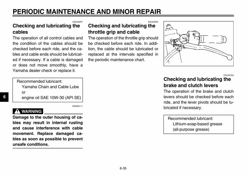
PE
6
ChcaThethechebleed or Ya
_
Dableandmobleun_
EAU03164
ecking and lubricating the ke and clutch levers operation of the brake and clutchrs should be checked before each, and the lever pivots should be lu-ated if necessary.
R
ecommended lubricant:Lithium-soap-based grease (all-purpose grease)
U5PW10.book Page 35 Thursday, January 10, 2002 12:15 PM
RIODIC MAINTENANCE AND MINOR REPAIR
6-35
EAU03297
ecking and lubricating the bles operation of all control cables and
condition of the cables should becked before each ride, and the ca-
s and cable ends should be lubricat-if necessary. If a cable is damageddoes not move smoothly, have amaha dealer check or replace it.
EW000111
WARNINGmage to the outer housing of ca-s may result in internal rusting cause interference with cablevement. Replace damaged ca-s as soon as possible to preventsafe conditions.
EAU04034
Checking and lubricating the throttle grip and cable The operation of the throttle grip shouldbe checked before each ride. In addi-tion, the cable should be lubricated orreplaced at the intervals specified inthe periodic maintenance chart.
ChbraTheleveridebric
ecommended lubricant:Yamaha Chain and Cable Lube orengine oil SAE 10W-30 (API SE)
R
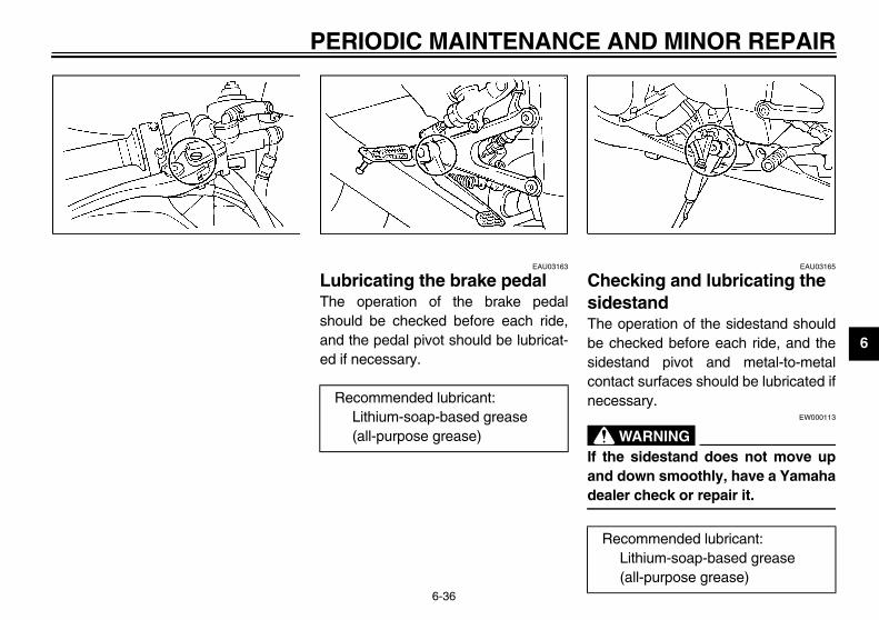
ND MINOR REPAIR
6
EAU03165
cking and lubricating the stand
operation of the sidestand shouldecked before each ride, and thetand pivot and metal-to-metalct surfaces should be lubricated ifssary.
EW000113
WARNING sidestand does not move up
down smoothly, have a Yamahar check or repair it.
commended lubricant:Lithium-soap-based grease (all-purpose grease)
U5PW10.book Page 36 Thursday, January 10, 2002 12:15 PM
PERIODIC MAINTENANCE A
6-36
EAU03163
Lubricating the brake pedal The operation of the brake pedalshould be checked before each ride,and the pedal pivot should be lubricat-ed if necessary.
ChesideThe be chsidescontanece
_
If theand deale_
Recommended lubricant:Lithium-soap-based grease (all-purpose grease)
Re

PE
6
ChTheforkinteten
To
_
Sethaove_
Chdam
EAU00794
king the steering r loose steering bearings mayanger. Therefore, the operationteering must be checked as fol- the intervals specified in the pe-maintenance and lubrication
ace a stand under the engine toise the front wheel off theound.
EW000115
ARNINGly support the motorcycle soere is no danger of it falling
U5PW10.book Page 37 Thursday, January 10, 2002 12:15 PM
RIODIC MAINTENANCE AND MINOR REPAIR
6-37
EAU02939
ecking the front fork condition and operation of the front must be checked as follows at thervals specified in the periodic main-ance and lubrication chart.
check the conditionEW000115
WARNINGcurely support the motorcycle sot there is no danger of it fallingr.
eck the inner tubes for scratches,age and excessive oil leakage.
To check the operation1. Place the motorcycle on a level
surface and hold it in an uprightposition.
2. While applying the front brake,push down hard on the handle-bars several times to check if thefront fork compresses and re-bounds smoothly.
EC000098
CAUTION:_
If any damage is found or the frontfork does not operate smoothly,have a Yamaha dealer check or re-pair it. _
ChecWorn ocause dof the slows atriodic chart.
1. Plragr
W_
Securethat thover. _

AND MINOR REPAIR
6
2
U5PW10.book Page 38 Thursday, January 10, 2002 12:15 PM
PERIODIC MAINTENANCE
6-38
. Hold the lower ends of the frontfork legs and try to move them for-ward and backward. If any freeplay can be felt, have a Yamahadealer check or repair the steer-ing.
EAU01144
Checking the wheel bearings The front and rear wheel bearings mustbe checked at the intervals specified inthe periodic maintenance and lubrica-tion chart. If there is play in the wheelhub or if the wheel does not turnsmoothly, have a Yamaha dealercheck the wheel bearings.

PE
6
BaThiseanotno add
ToHateryhavbatif thtion
KEEP THIS AND ALL BATTER-IES OUT OF THE REACH OFCHILDREN.
store the batteryIf the motorcycle will not be usedfor more than one month, removethe battery, fully charge it, andthen place it in a cool, dry place.If the battery will be stored formore than two months, check it atleast once a month and fullycharge it if necessary.Fully charge the battery before in-stallation.After installation, make sure thatthe battery leads are properly con-nected to the battery terminals.
1. B
U5PW10.book Page 39 Thursday, January 10, 2002 12:15 PM
RIODIC MAINTENANCE AND MINOR REPAIR
6-39
EAU01291
ttery s motorcycle is equipped with aled-type (MF) battery, which does require any maintenance. There isneed to check the electrolyte or to distilled water.
charge the batteryve a Yamaha dealer charge the bat- as soon as possible if it seems toe discharged. Keep in mind that thetery tends to discharge more quicklye motorcycle is equipped with op-al electrical accessories.
EW000116
WARNING_
� Electrolyte is poisonous anddangerous since it contains sul-furic acid, which causes severeburns. Avoid any contact withskin, eyes or clothing and al-ways shield your eyes whenworking near batteries. In caseof contact, administer the fol-lowing FIRST AID.• EXTERNAL: Flush with plenty
of water.• INTERNAL: Drink large quan-
tities of water or milk and im-mediately call a physician.
• EYES: Flush with water for15 minutes and seek promptmedical attention.
� Batteries produce explosive hy-drogen gas. Therefore, keepsparks, flames, cigarettes, etc.,away from the battery and pro-vide sufficient ventilation whencharging it in an enclosedspace.
�
_
To 1.
2.
3.
4.
attery

AND MINOR REPAIR
6
C_
_
. Remove the blown fuse, and theninstall a new fuse of the specifiedamperage.
Main fuseElectronic fuel injection fuseElectronic fuel injection spare fuse
Specified fuses:Main fuse: 50 AHeadlight fuse: 20 ASignaling system fuse: 15 ARadiator fan fuse: 15 AIgnition fuse: 15 AElectronic fuel injection fuse:15 ABackup fuse (odometer and clock): 5 A
U5PW10.book Page 40 Thursday, January 10, 2002 12:15 PM
PERIODIC MAINTENANCE
6-40
EC000102
AUTION:� Always keep the battery
charged. Storing a dischargedbattery can cause permanentbattery damage.
� To charge a sealed-type (MF)battery, a special (constant-voltage) battery charger is re-quired. Using a conventionalbattery charger will damage thebattery. If you do not have ac-cess to a sealed-type (MF) bat-tery charger, have a Yamahadealer charge your battery.
EAU04548*
Replacing the fuses The main fuse and the electronic fuelinjection fuse are located under the rid-er seat. (See page 3-15 for rider seatremoval and installation procedures.)The fuse box, which contains the fusesfor the individual circuits, is located un-der panel B. (See page 6-11 for panelremoval and installation procedures.)If a fuse is blown, replace it as follows.
1. Turn the key to “OFF” and turn offthe electrical circuit in question.
2
1. Headlight fuse2. Signaling system fuse3. Ignition fuse4. Radiator fan fuse5. Backup fuse (odometer and clock)6. Spare fuse (× 3)
1.2.3.
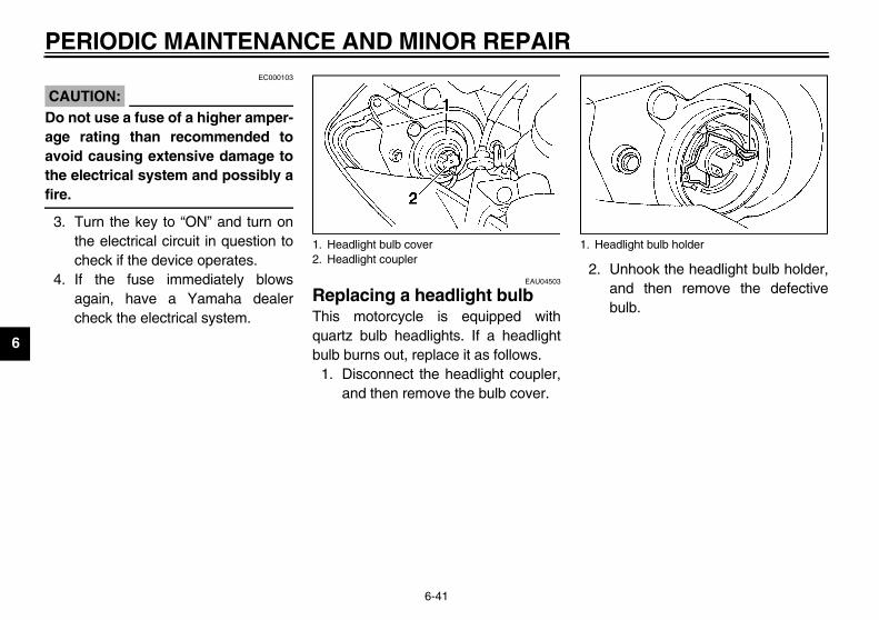
PE
6
CA_
Doageavothefire_
3.
4.nhook the headlight bulb holder,nd then remove the defectiveulb.
light bulb holder
U5PW10.book Page 41 Thursday, January 10, 2002 12:15 PM
RIODIC MAINTENANCE AND MINOR REPAIR
6-41
EC000103
UTION: not use a fuse of a higher amper- rating than recommended toid causing extensive damage to electrical system and possibly a.
Turn the key to “ON” and turn onthe electrical circuit in question tocheck if the device operates.If the fuse immediately blowsagain, have a Yamaha dealercheck the electrical system.
EAU04503
Replacing a headlight bulb This motorcycle is equipped withquartz bulb headlights. If a headlightbulb burns out, replace it as follows.
1. Disconnect the headlight coupler,and then remove the bulb cover.
2. Uab
1. Headlight bulb cover2. Headlight coupler
1. Head

AND MINOR REPAIR
6
_
Hfofrtodo_
3
EAU03730
il/brake light is motorcycle is equipped with anD type of tail/brake light.
the tail/brake light does not come on,ve a Yamaha dealer check it.
1.
U5PW10.book Page 42 Thursday, January 10, 2002 12:15 PM
PERIODIC MAINTENANCE
6-42
EW000119
WARNINGeadlight bulbs get very hot. There-re, keep flammable products awayom a lit headlight bulb, and do notuch the bulb until it has cooledwn.
. Place a new headlight bulb intoposition, and then secure it withthe bulb holder.
EC000104
CAUTION:_
Take care not to damage the follow-ing parts:
� Headlight bulbDo not touch the glass part ofthe headlight bulb to keep it freefrom oil, otherwise the transpar-ency of the glass, the luminosi-ty of the bulb, and the bulb lifewill be adversely affected. Thor-oughly clean off any dirt and fin-gerprints on the headlight bulbusing a cloth moistened with al-cohol or thinner.
� Headlight lens• Do not affix any type of tinted
film or stickers to the head-light lens.
• Do not use a headlight bulb ofa wattage higher than speci-fied.
_
4. Install the headlight bulb cover,and then connect the coupler.
5. Have a Yamaha dealer adjust theheadlight beam if necessary.
TaThLEIf ha
Do not touch the glass part of the bulb.

PE
6
Rebu
1.
2.
3.
4.
EAU04574
placing the license plate ht bulb
Remove the license plate light unitby removing the screws.
1. S crew (× 2)
U5PW10.book Page 43 Thursday, January 10, 2002 12:15 PM
RIODIC MAINTENANCE AND MINOR REPAIR
6-43
EAU03497
placing a turn signal light lb
Remove the turn signal light lensby removing the screw.Remove the defective bulb bypushing it in and turning it counter-clockwise.Insert a new bulb into the socket,push it in, and then turn it clock-wise until it stops.Install the lens by installing thescrew.
ECA00065
CAUTION:_
Do not overtighten the screw, other-wise the lens may break. _
Relig
1.
crew 1. S

ND MINOR REPAIR
6
2
3
45
6
ervice the rear wheele the rear wheel off the ground byg a motorcycle stand or, if a motor- stand is not available, by placing
ck either under each side of thee in front of the rear wheel or under side of the swingarm.
1.2.
U5PW10.book Page 44 Thursday, January 10, 2002 12:15 PM
PERIODIC MAINTENANCE A
6-44
. Remove the socket (together withthe bulb) by pulling it out.
. Remove the defective bulb by pull-ing it out.
. Insert a new bulb into the socket.
. Install the socket (together withthe bulb) by pushing it in.
. Install the license plate light unit byinstalling the screws.
EAU01579
Supporting the motorcycle Since this model is not equipped with acenterstand, follow these precautionswhen removing the front and rearwheel or performing other mainte-nance requiring the motorcycle tostand upright. Check that the motor-cycle is in a stable and level positionbefore starting any maintenance. Astrong wooden box can be placed un-der the engine for added stability.
To service the front wheel1. Stabilize the rear of the motorcycle
by using a motorcycle stand or, ifan additional motorcycle stand isnot available, by placing a jack un-der the frame in front of the rearwheel.
2. Raise the front wheel off theground by using a motorcyclestand.
To sRaisusincyclea jaframeach
License plate light bulbLicense plate light unit
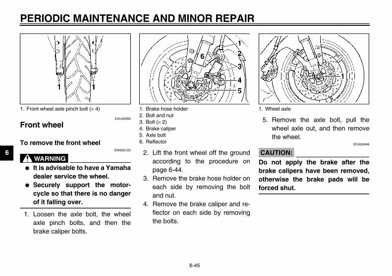
PE
6
Fr
To
_
�
�
_
1.
Remove the axle bolt, pull thewheel axle out, and then removethe wheel.
ECA00046
UTION: not apply the brake after theke calipers have been removed,erwise the brake pads will beced shut.
1. F heel axle
U5PW10.book Page 45 Thursday, January 10, 2002 12:15 PM
RIODIC MAINTENANCE AND MINOR REPAIR
6-45
EAU04569
ont wheel
remove the front wheel EW000122
WARNINGIt is advisable to have a Yamahadealer service the wheel.Securely support the motor-cycle so that there is no dangerof it falling over.
Loosen the axle bolt, the wheelaxle pinch bolts, and then thebrake caliper bolts.
2. Lift the front wheel off the groundaccording to the procedure onpage 6-44.
3. Remove the brake hose holder oneach side by removing the boltand nut.
4. Remove the brake caliper and re-flector on each side by removingthe bolts.
5.
CA_
Dobraothfor_
ront wheel axle pinch bolt (× 4) 1. Brake hose holder2. Bolt and nut3. Bolt (× 2)4. Brake caliper5. Axle bolt6. Reflector
1. W

AND MINOR REPAIR
6
To1
23
4
N_
Mbeindi_
5
. Tap the outer side of the right forkleg with a rubber mallet to align itwith the end of the wheel axle.
. Tighten wheel axle pinch bolts Cand D to the specified torque.
. While applying the front brake,push down hard on the handlebarseveral times to check for properfork operation.
Tightening torque:Wheel axle pinch bolt:
18 Nm (1.8 m·kgf, 13 ft·lbf)
Tightening torque:Wheel axle pinch bolt:
18 Nm (1.8 m·kgf, 13 ft·lbf)
U5PW10.book Page 46 Thursday, January 10, 2002 12:15 PM
PERIODIC MAINTENANCE
6-46
EAU04662
install the front wheel . Lift the wheel up between the fork
legs.. Insert the wheel axle.. Lower the front wheel so that it is
on the ground.. Install the brake calipers and re-
flectors by installing the bolts, andthen tightening them to the speci-fied torque.
OTE:ake sure that there is enough spacetween the brake pads before install-
g the brake calipers onto the brakescs.
. Install the brake hose holders byinstalling the bolts and nuts.
6. Secure the wheel axle by installingthe axle bolt, and then tightening itto the specified torque.
NOTE:_
While tightening the axle bolt, hold thewheel axle with a 19-mm hexagonwrench to keep it from turning. _
7. Tighten wheel axle pinch bolts Aand B to the specified torque.
8
9
10
Tightening torque:Brake caliper bolt:
40 Nm (4.0 m·kgf, 29 ft·lbf)
1. Front wheel axle pinch bolt A2. Front wheel axle pinch bolt B3. Front wheel axle pinch bolt C4. Front wheel axle pinch bolt D
Tightening torque:Axle bolt:
91 Nm (9.1 m·kgf, 66 ft·lbf)

PE
6
Re
To
_
�
�
_
1.
2.
sh the wheel forward, and thenmove the drive chain from thear sprocket.
:rive chain does not need to beembled in order to remove andthe rear wheel.
1. A2. D3. L
U5PW10.book Page 47 Thursday, January 10, 2002 12:15 PM
RIODIC MAINTENANCE AND MINOR REPAIR
6-47
EAU04533
ar wheel
remove the rear wheel EW000122
WARNINGIt is advisable to have a Yamahadealer service the wheel.Securely support the motor-cycle so that there is no dangerof it falling over.
Loosen the axle nut and the brakecaliper bolts.Lift the rear wheel off the groundaccording to the procedure onpage 6-44.
3. Remove the axle nut, and then re-move the brake caliper by remov-ing the bolts.
4. Loosen the locknut on each side ofthe swingarm.
5. Turn the drive chain slack adjust-ing bolts fully in direction a.
6. Purere
NOTE_
The ddisassinstall _
xle nutrive chain slack adjusting boltocknut
1. Bolt (× 2)2. Brake caliper3. Brake caliper bracket

ND MINOR REPAIR
6
7
8
C_
Dwwbrou_
1.
htening torques:Axle nut:
150 Nm (15.0 m·kgf, 108 ft·lbf)Brake caliper bolt:
27 Nm (2.7 m·kgf, 19.5 ft·lbf)
U5PW10.book Page 48 Thursday, January 10, 2002 12:15 PM
PERIODIC MAINTENANCE A
6-48
. While supporting the brake caliperbracket, pull the wheel axle out.
. Remove the wheel.ECA00119
AUTION:o not apply the brake after theheel has been removed togetherith the brake disc, otherwise theake caliper pistons will be forcedt.
EAU04534
To install the rear wheel 1. Install the wheel and the brake cal-
iper bracket by inserting the wheelaxle from the left-hand side.
NOTE:_
Make sure that there is enough spacebetween the brake pads before install-ing the wheel. _
2. Install the drive chain onto the rearsprocket, and then adjust the drivechain slack. (See page 6-33 fordrive chain slack adjustment pro-cedures.)
3. Install the axle nut, and then lowerthe rear wheel so that it is on theground.
4. Install the brake caliper by install-ing the bolts.
5. Tighten the axle nut and the brakecaliper bolts to the specifiedtorques.
Wheel axle
Tig

PE
6
TrAltha thfromingcomexalosTherepfor selreqdeatheknoproUsmelikeinfecan
U5PW10.book Page 49 Thursday, January 10, 2002 12:15 PM
RIODIC MAINTENANCE AND MINOR REPAIR
6-49
EAU03087
oubleshooting ough Yamaha motorcycles receiveorough inspection before shipment the factory, trouble may occur dur-
operation. Any problem in the fuel,pression, or ignition systems, formple, can cause poor starting and
s of power. following troubleshooting charts
resent quick and easy procedureschecking these vital systems your-f. However, should your motorcycleuire any repair, take it to a Yamahaler, whose skilled technicians have
necessary tools, experience, andw-how to service the motorcycleperly.e only genuine Yamaha replace-nt parts. Imitation parts may look Yamaha parts, but they are oftenrior, have a shorter service life and lead to expensive repair bills.

AND MINOR REPAIR
6
EAU02990
TroubleshootinStarting problems
EW000125
WARNING_
Keep away open fl ystem. _
CT-1AE
s not start. pression.
The engine does not start.Have a Yamaha dealercheck the vehicle.
e engine does not start.eck the battery.
en the throttle halfway and operate electric starter.
U5PW10.book Page 50 Thursday, January 10, 2002 12:15 PM
Check the fuel lethe fuel tank.
1. Fuel
Operate the elec
2. Compre
Remove the spaand check the el
3. Ignition
Operate the elec
4. Battery
PERIODIC MAINTENANCE
6-50
g charts or poor engine performance
ames and do not smoke while checking or working on the fuel s
vel inThere is enough fuel.
There is no fuel.
Check the compression.
Supply fuel. The engine doeCheck the com
tric starter.
ssionThere is compression.
There is no compression.
Check the ignition.
Have a Yamaha dealercheck the vehicle.
rk plugsectrodes.
Wipe off with a dry cloth and correct thespark plug gaps, or replace the spark plugs.
Have a Yamaha dealer check the vehicle. ThCh
tric starter.
The engine turns over quickly.
The engine turns over slowly.
The battery is good.
Check the battery lead connections,and charge the battery if necessary.
Dry
WetOpthe

PE
6
EnEW000070
_
� ding hot fluid and steam may be until the engine has cooled.
� l, over the radiator cap, and thenessure to escape. When the hiss-wise, and then remove the cap.
_
CT-2A
NO_
If c anged to the recommended coolantas _
Have a Yamaha dealer checkand repair the cooling system.
Add coolant. (See NOTE.)
f the engine overheats again, have a eck and repair the cooling system.
ise.
is age.
U5PW10.book Page 51 Thursday, January 10, 2002 12:15 PM
RIODIC MAINTENANCE AND MINOR REPAIR
6-51
gine overheating
WARNINGDo not remove the radiator cap when the engine and radiator are hot. Scalblown out under pressure, which could cause serious injury. Be sure to waitAfter removing the radiator cap retaining bolt, place a thick rag, like a toweslowly rotate the cap counterclockwise to the detent to allow any residual pring sound has stopped, press down on the cap while turning it counterclock
E
TE:oolant is not available, tap water can be temporarily used instead, provided that it is chsoon as possible.
Wait until the engine has cooled.
Check the coolant level in the reservoir and radiator.
The coolant level is OK.
The coolant level is low.Check the cooling systemfor leakage.
Start the engine. IYamaha dealer ch
There leakag
There no leak

MOTORCYCLE CARE AND STORAGE
7
Care .................................................................................................. 7-1Storage .............................................................................................. 7-4
U5PW10.book Page 1 Thursday, January 10, 2002 12:15 PM

7
EAU04571
aningECA00056
UTION:
U5PW10.book Page 1 Thursday, January 10, 2002 12:15 PM
7-MO
CaWhreve
Avoid using strong acidic wheelcleaners, especially on spokedwheels. If such products areused on hard-to-remove dirt, donot leave the cleaner on the af-fected area any longer than in-structed. Also, thoroughly rinsethe area off with water, immedi-ately dry it, and then apply acorrosion protection spray.Improper cleaning can damagewindshields, cowlings, panels,other plastic parts, and the muf-fler. Use only a soft, clean clothor sponge with mild detergentand water to clean plastic. How-ever, if the muffler cannot bethoroughly cleaned with milddetergent, alkaline productsand a soft brush may be used.
noloble.eveusenotifrommodoethe moand
7-1
TORCYCLE CARE AND STORAGE
re ile the open design of a motorcycleals the attractiveness of the tech-gy, it also makes it more vulnera- Rust and corrosion can developn if high-quality components ared. A rusty exhaust pipe may go un-ced on a car, however, it detracts the overall appearance of a
torcycle. Frequent and proper cares not only comply with the terms ofwarranty, but it will also keep your
torcycle looking good, extend its life optimize its performance.
Before cleaning1. Cover the muffler outlet with a
plastic bag after the engine hascooled down.
2. Make sure that all caps and coversas well as all electrical couplersand connectors, including thespark plug caps, are tightly in-stalled.
3. Remove extremely stubborn dirt,like oil burnt onto the crankcase,with a degreasing agent and abrush, but never apply such prod-ucts onto seals, gaskets, sprock-ets, the drive chain and wheelaxles. Always rinse the dirt anddegreaser off with water.
Cle
CA_
�
�

ARE AND STORAGE
7
ter riding in the rain, near the sea or salt-sprayed roadsnce sea salt or salt sprayed on roadsring winter are extremely corrosive inmbination with water, carry out thellowing steps after each ride in thein, near the sea or on salt-sprayedads.
TE:lt sprayed on roads in the winter may
main well into spring.
. Clean the motorcycle with coldwater and a mild detergent, afterthe engine has cooled down.
ECA00012
AUTION: not use warm water since it in-
eases the corrosive action of thelt.
. After drying the motorcycle, applya corrosion protection spray on allmetal, including chrome- and nick-el-plated, surfaces (except the tita-nium muffler) to prevent corrosion.
U5PW10.book Page 2 Thursday, January 10, 2002 12:15 PM
MOTORCYCLE C
7-2
� Do not use any harsh chemicalproducts on plastic parts or themuffler. Be sure to avoid usingcloths or sponges which havebeen in contact with strong orabrasive cleaning products, sol-vent or thinner, fuel (gasoline),rust removers or inhibitors,brake fluid, antifreeze or elec-trolyte.
� Do not use high-pressure wash-ers or steam-jet cleaners sincethey cause water seepage anddeterioration in the following ar-eas: seals (of wheel and swing-arm bearings, fork and brakes),storage compartments, electriccomponents (couplers, connec-tors, instruments, switches andlights), breather hoses andvents.
� For motorcycles equipped witha windshield: Do not use strongcleaners or hard sponges asthey will cause dulling orscratching. Some cleaningcompounds for plastic mayleave scratches on the wind-shield. Test the product on asmall hidden part of the wind-shield to make sure that it doesnot leave any marks. If the wind-shield is scratched, use a quali-ty plastic polishing compoundafter washing.
_
After normal useRemove dirt with warm water, a milddetergent, and a soft, clean sponge,and then rinse thoroughly with cleanwater. Use a toothbrush or bottlebrushfor hard-to-reach areas. Stubborn dirtand insects will come off more easily ifthe area is covered with a wet cloth fora few minutes before cleaning.
AfonSiducoforaro
NO_
Sare_
1
C_
Docrsa_
2

M
7
CleThimuspe
�
�
�
�
EWA00031
WARNINGMake sure that there is no oil orwax on the brakes or tires.If necessary, clean the brakediscs and brake linings with aregular brake disc cleaner or ac-etone, and wash the tires withwarm water and a mild deter-gent. Before riding at higherspeeds, test the motorcycle’sbraking performance and cor-nering behavior.
U5PW10.book Page 3 Thursday, January 10, 2002 12:15 PM
OTORCYCLE CARE AND STORAGE
7-3
aning the titanium mufflers model is equipped with a titaniumffler, which requires the followingcial care.Use only a soft, clean cloth orsponge with mild detergent andwater to clean the titanium muffler.However, if the muffler cannot bethoroughly cleaned with mild de-tergent, alkaline products and asoft brush may be used.Never use compounds or otherspecial treatments to clean the ti-tanium muffler, as they will removethe finish on the outer surface ofthe muffler.Even the smallest amounts of oil,such as from oily towels or finger-prints, will leave stains on the tita-nium muffler, which can beremoved with a mild detergent.Note that the thermally induceddiscoloring of the portion of the ex-haust pipe leading into the titani-um muffler is normal and cannotbe removed.
After cleaning1. Dry the motorcycle with a chamois
or an absorbing cloth.2. Immediately dry the drive chain
and lubricate it to prevent it fromrusting.
3. Use a chrome polish to shinechrome, aluminum and stainless-steel parts.
4. To prevent corrosion, it is recom-mended to apply a corrosion pro-tection spray on all metal,including chrome- and nickel-plat-ed, surfaces.
5. Use spray oil as a universal clean-er to remove any remaining dirt.
6. Touch up minor paint damagecaused by stones, etc.
7. Wax all painted surfaces.8. Let the motorcycle dry completely
before storing or covering it.
_
�
�
_

ARE AND STORAGE
7
C_
_
N_
Cw_
ng-termfore storing your motorcycle forveral months:. Follow all the instructions in the
“Care” section of this chapter.. Fill up the fuel tank and add fuel
stabilizer (if available) to preventthe fuel tank from rusting and thefuel from deteriorating.
. Perform the following steps to pro-tect the cylinders, piston rings, etc.from corrosion.
U5PW10.book Page 4 Thursday, January 10, 2002 12:15 PM
MOTORCYCLE C
7-4
ECA00013
AUTION:� Apply spray oil and wax spar-
ingly and make sure to wipe offany excess.
� Never apply oil or wax to anyrubber and plastic parts, buttreat them with a suitable careproduct.
� Avoid using abrasive polishingcompounds as they will wearaway the paint.
OTE:onsult a Yamaha dealer for advice onhat products to use.
Storage
Short-termAlways store your motorcycle in a cool,dry place and, if necessary, protect itagainst dust with a porous cover.
ECA00014
CAUTION:_
� Storing the motorcycle in apoorly ventilated room or cover-ing it with a tarp, while it is stillwet, will allow water and humid-ity to seep in and cause rust.
� To prevent corrosion, avoiddamp cellars, stables (becauseof the presence of ammonia)and areas where strong chemi-cals are stored.
_
LoBese
1
2
3

M
7
a
b
c
d
e
_
Tospaspathe_
TE:ke any necessary repairs beforering the motorcycle.
U5PW10.book Page 5 Thursday, January 10, 2002 12:15 PM
OTORCYCLE CARE AND STORAGE
7-5
. Remove the spark plug caps andspark plugs.
. Pour a teaspoonful of engine oilinto each spark plug bore.
. Install the spark plug caps onto thespark plugs, and then place thespark plugs on the cylinder headso that the electrodes are ground-ed. (This will limit sparking duringthe next step.)
. Turn the engine over several timeswith the starter. (This will coat thecylinder walls with oil.)
. Remove the spark plug caps fromthe spark plugs, and then installthe spark plugs and the spark plugcaps.
EWA00003
WARNING prevent damage or injury fromrking, make sure to ground therk plug electrodes while turning engine over.
4. Lubricate all control cables andthe pivoting points of all levers andpedals as well as of the sidestand/centerstand.
5. Check and, if necessary, correctthe tire air pressure, and then liftthe motorcycle so that both of itswheels are off the ground. Alterna-tively, turn the wheels a little everymonth in order to prevent the tiresfrom becoming degraded in onespot.
6. Cover the muffler outlet with aplastic bag to prevent moisturefrom entering it.
7. Remove the battery and fullycharge it. Store it in a cool, dryplace and charge it once a month.Do not store the battery in an ex-cessively cold or warm place [lessthan 0 °C (30 °F) or more than30 °C (90 °F)]. For more informa-tion on storing the battery, seepage 6-39.
NO_
Masto_

SPECIFICATIONS
8
Specifications .................................................................................... 8-1
U5PW10.book Page 1 Thursday, January 10, 2002 12:15 PM

8
EAU01038
U5PW10.book Page 1 Thursday, January 10, 2002 12:15 PM
8-SP
SpCS-01
M
oil API Service SE, SF, SG or higher
ridge 2.9 L (2.55 lmp qt, 3.07 US qt)
e 3.1 L (2.73 lmp qt, 3.28 US qt)
gine) 3.8 L (3.34 lmp qt, 4.02 US qt)
0 10 30 50 70 90 110 130 ˚F
YAMALUBE 4 (20W-40)or SAE 20W-40
-20 -10 0 10 20 30 40 50 ˚C
YAMALUBE 4 (10W-30)or SAE 10W-30
tor oils that do not contain anti-frictionger car motor oils (often labeledVING II”) contain anti-friction additivestch and/or starter clutch slippage, result-
ponent life and poor engine performance.
D
Bf
E
8-1
ECIFICATIONS
ecifications E
odel YZF-R1/YZF-R1C
imensions
Overall length 2,040 mm (80.3 in)
Overall width 705 mm (27.8 in)
Overall height 1,105 mm (43.5 in)
Seat height 820 mm (32.3 in)
Wheelbase 1,395 mm (54.9 in)
Ground clearance 140 mm (5.5 in)
Minimum turning radius 3,900 mm (153.5 in)
asic weight (with oil and full uel tank)
YZF-R1: 193 kg (426 lb)YZF-R1C: 194 kg (428 lb)
ngine
Engine type Liquid-cooled 4-stroke, DOHC
Cylinder arrangement Forward-inclined parallel 4-cylinder
Displacement 998 cm3
Bore × stroke 74 × 58 mm (2.91 × 2.28 in)
Compression ratio 11.8:1
Starting system Electric starter
Lubrication system Wet sump
Engine oil
Type
Recommended engine classification
Quantity
Without oil filter cartreplacement
With oil filter cartridgreplacement
Total amount (dry en
CAUTION:
Be sure to use momodifiers. Passen“ENERGY CONSERwhich will cause cluing in reduced com
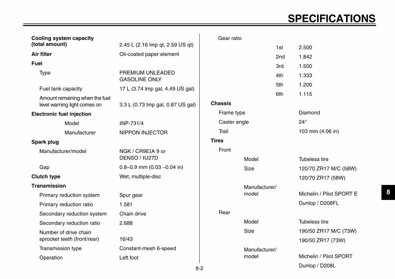
SPECIFICATIONS
8
t 2.500
d 1.842
d 1.500
h 1.333
h 1.200
h 1.115
Diamond
24°
103 mm (4.06 in)
Tubeless tire
120/70 ZR17 M/C (58W)
120/70 ZR17 (58W)
Michelin / Pilot SPORT E
Dunlop / D208FL
Tubeless tire
190/50 ZR17 M/C (73W)
190/50 ZR17 (73W)
Michelin / Pilot SPORT
Dunlop / D208L
U5PW10.book Page 2 Thursday, January 10, 2002 12:15 PM
8-2
Cooling system capacity (total amount) 2.45 L (2.16 lmp qt, 2.59 US qt)
Air filter Oil-coated paper element
Fuel
Type PREMIUM UNLEADED GASOLINE ONLY
Fuel tank capacity 17 L (3.74 lmp gal, 4.49 US gal)
Amount remaining when the fuel level warning light comes on 3.3 L (0.73 lmp gal, 0.87 US gal)
Electronic fuel injection
Model INP-731/4
Manufacturer NIPPON INJECTOR
Spark plug
Manufacturer/model NGK / CR9EIA 9 or DENSO / IU27D
Gap 0.8–0.9 mm (0.03 –0.04 in)
Clutch type Wet, multiple-disc
Transmission
Primary reduction system Spur gear
Primary reduction ratio 1.581
Secondary reduction system Chain drive
Secondary reduction ratio 2.688
Number of drive chain sprocket teeth (front/rear) 16/43
Transmission type Constant-mesh 6-speed
Operation Left foot
Gear ratio
1s
2n
3r
4t
5t
6t
Chassis
Frame type
Caster angle
Trail
Tires
Front
Model
Size
Manufacturer/model
Rear
Model
Size
Manufacturer/model

SP
8
Single disc brake
Right foot
DOT 4
Telescopic fork
Swingarm (link suspension)
Coil spring / oil damper
Coil spring / gas-oil damper
120 mm (4.72 in)
130 mm (5.12 in)
T.C.I. (digital)
A.C. magneto
14 V, 32 A@ 5,000 r/min
GT12B-4
y 12 V, 10 Ah
Quartz bulb (halogen)
U5PW10.book Page 3 Thursday, January 10, 2002 12:15 PM
ECIFICATIONS
8-3
Maximum load* YZF-R1: 202 kg (445 lb)
YZF-R1C: 201 kg (443 lb)
Tire air pressure (measured on cold tires)
Up to 90 kg (198 lb)*
Front 250 kPa (2.50 kgf/cm2, 36 psi)
Rear 250 kPa (2.50 kgf/cm2, 36 psi)
90 kg (198 lb)–maximum*
Front 250 kPa (2.50 kgf/cm2, 36 psi)
Rear 290 kPa (2.90 kgf/cm2, 42 psi)
High-speed riding
Front 250 kPa (2.50 kgf/cm2, 36 psi)
Rear 250 kPa (2.50 kgf/cm2, 36 psi)
* Total weight of rider, passenger, cargo and accessories
Wheels
Front
Type Cast wheel
Size 17 M/C × MT 3.50
Rear
Type Cast wheel
Size 17 M/C × MT 6.00
Brakes
Front
Type Dual disc brake
Operation Right hand
Fluid DOT 4
Rear
Type
Operation
Fluid
Suspension
Front
Rear
Spring/shock absorber
Front
Rear
Wheel travel
Front
Rear
Electrical system
Ignition system
Charging system
Type
Standard output
Battery
Model
Voltage, capacit
Headlight type

SPECIFICATIONS
8
U5PW10.book Page 4 Thursday, January 10, 2002 12:15 PM
8-4
Bulb voltage, wattage × quantity
Headlight 12 V, 60/55 W × 2
Tail/brake light L.E.D.
Front turn signal/position light 12 V, 21/5 W × 2
Rear turn signal light 12 V, 21 W × 2
Auxiliary light 12 V, 5 W × 2
License plate light 12 V, 5 W × 1
Meter lighting L.E.D.
Neutral indicator light L.E.D.
High beam indicator light L.E.D.
Turn signal indicator light L.E.D.
Fuel level warning light L.E.D.
Oil level warning light L.E.D.
Engine trouble warning light L.E.D.
Engine speed indicator light L.E.D.
Fuses
Main fuse 50 A
Headlight fuse 20 A
Signaling system fuse 15 A
Radiator fan fuse 15 A
Ignition fuse 15 A
Backup fuse (odometer and clock) 5 A
Electronic fuel injection fuse 15 A

CONSUMER INFORMATION
9
Identification numbers ....................................................................... 9-1Key identification number .................................................................. 9-1Vehicle identification number ............................................................. 9-1Model label ........................................................................................ 9-2Reporting safety defects ................................................................... 9-3Motorcycle noise regulation .............................................................. 9-4Maintenance record .......................................................................... 9-5YAMAHA MOTOR CORPORATION, U.S.A. STREET AND
ENDURO MOTORCYCLE LIMITED WARRANTY .......................... 9-7YAMAHA EXTENDED SERVICE (Y.E.S.) ......................................... 9-9
U5PW10.book Page 1 Thursday, January 10, 2002 12:15 PM

9
EAU01039
U5PW10.book Page 1 Thursday, January 10, 2002 12:15 PM
9-CO
IdeRec
EAU01043
hicle identification number vehicle identification number is
mped into the steering head pipe.ord this number in the space pro-d.
TE: vehicle identification number isd to identify your motorcycle andy be used to register your motor-le with the licensing authority inr area.
ehicle identification number
vehel lavideorddeacle
1.CA-02
2.
CA-02
3.CA-01
9-1
NSUMER INFORMATIONEAU02944
ntification numbers ord the key identification number,icle identification number and mod-bel information in the spaces pro-d below for assistance when
ering spare parts from a Yamahaler or for reference in case the vehi-is stolen.
KEY IDENTIFICATION NUMBER:E
VEHICLE IDENTIFICATION NUMBER:
E
MODEL LABEL INFORMATION:E
EAU01041
Key identification number The key identification number isstamped into the key tag. Record thisnumber in the space provided and useit for reference when ordering a newkey.
VeThestaRecvide
NO_
Theusemacycyou_
1. Key identification number 1. V

MER INFORMATION
9
MThun3-infoviwYa
1.
U5PW10.book Page 2 Thursday, January 10, 2002 12:15 PM
CONSU
9-2
EAU04490
odel label e model label is affixed to the frameder the passenger seat. (See page16 for passenger seat removal andstallation procedures.) Record the in-rmation on this label in the space pro-ded. This information will be neededhen ordering spare parts from amaha dealer.
Model label
CO
9
EAU01051
ReIf y injury or death, you should immedi-ate otifying Yamaha Motor Corporation,U.S that a safety defect exists in a groupof v me involved in individual problemsbetTo 3 (or 366-0123 in Washington, D.C.are . You can also obtain other informa-tion
U5PW10.book Page 3 Thursday, January 10, 2002 12:15 PM
NSUMER INFORMATION
9-3
porting safety defects ou believe that your vehicle has a defect which could cause a crash or could cause ly inform the National Highway Traffic Safety Administration (NHTSA) in addition to n.A. If NHTSA receives similar complaints, it may open an investigation, and if it finds ehicles, it may order a recall and remedy campaign. However, NHTSA cannot becoween you, your dealer, or Yamaha Motor Corporation, U.S.A.contact NHTSA, you may either call the Auto Safety Hotline toll-free at 1-800-424-939a) or write to: NHTSA, U.S. Department of Transportation, Washington, D.C. 20590 about motor vehicle safety from the Hotline.

MER INFORMATION
9
EAU01053
MTAFe ering inoperative by any person otherth design incorporated into any new ve-hi r or while it is in use or (2) the use ofth erative by any person.“A S LISTED BELOW”.Th tc.CL-
U5PW10.book Page 4 Thursday, January 10, 2002 12:15 PM
CONSU
9-4
otorcycle noise regulation MPERING WITH NOISE CONTROL SYSTEM PROHIBITED:deral law prohibits the following acts or the causing thereof: (1) The removal or rend
an for purposes of maintenance, repair, or replacement of any device or element of cle for the purpose of noise control prior to its sale or delivery to the ultimate purchasee vehicle after such device or element of design has been removed or rendered inopMONG THOSE ACTS PRESUMED TO CONSTITUTE TAMPERING ARE THE ACTese acts include tampering with the following systems; i.e., modification, removal, e
01E
Exhaust systemMufflerExhaust pipeSilencer
Intake systemAir cleaner caseAir cleaner elementIntake duct

CO
9
EAU01874
MaCo cle will be required to document thatma t below is printed only as a reminderthaCL-04
leress
Remarks
U5PW10.book Page 5 Thursday, January 10, 2002 12:15 PM
NSUMER INFORMATION
9-5
intenance record pies of work orders and/or receipts for parts purchased and installed on your motorcyintenance has been completed in accordance with the emissions warranty. The chart maintenance work is required. It is not acceptable proof of maintenance work.E
Maintenanceinterval
Date ofservice
MileageServicing dea
name and addr
600 mi(1,000 km) or
1 month
4,000 mi( 7,000 km) or
6 months
8,000 mi(13,000 km) or
12 months
12,000 mi(19,000 km) or
18 months
16,000 mi(25,000 km) or
24 months
20,000 mi(31,000 km) or
30 months
24,000 mi(37,000 km) or
36 months

MER INFORMATION
9
alerress
Remarks
U5PW10.book Page 6 Thursday, January 10, 2002 12:15 PM
CONSU
9-6
28,000 mi(43,000 km) or
42 months
32,000 mi(49,000 km) or
48 months
36,000 mi(55,000 km) or
54 months
40,000 mi(61,000 km) or
60 months
Maintenanceinterval
Date ofservice
MileageServicing de
name and add

CO
9
EAU02918
. ARRANTY
U5PW10.book Page 7 Thursday, January 10, 2002 12:15 PM
NSUMER INFORMATION
9-7
YAMAHA MOTOR CORPORATION, U.S.ASTREET AND ENDURO MOTORCYCLE LIMITED W

MER INFORMATION
9
U5PW10.book Page 8 Thursday, January 10, 2002 12:15 PM
CONSU
9-8

CO
9
EAU01063
U5PW10.book Page 9 Thursday, January 10, 2002 12:15 PM
NSUMER INFORMATION
9-9
YAMAHA EXTENDED SERVICE (Y.E.S.)

MER INFORMATION
9
U5PW10.book Page 10 Thursday, January 10, 2002 12:15 PM
CONSU
9-10

D
ce f
ttakheakakakakakakakak
bnretattoCCowm
dentification numbers ..............................9-1gnition circuit cut-off system ..................3-24ndicator and warning lights......................3-2
ey identification number .........................9-1
abels, location ........................................1-7icense plate light bulb, replacing...........6-43uggage strap holders ...........................3-23
ain switch/steering lock .........................3-1aintenance and lubrication, periodic ......6-5aintenance, emission control system.....6-3aintenance, periodic ..............................6-1aintenance record .................................9-5odel label ..............................................9-2ulti-function display................................3-6
eutral indicator light ...............................3-3oise regulation .......................................9-4
il level warning light ...............................3-3
U5PW10.book Page 1 Thursday, January 10, 2002 12:15 PM
IN
AAcAir
BBaBr
cBrBrBrBrBrBrBrBr
CCaCaCaCaCluCluCo
CoCo
re
e pedal position, adjusting ..............6-29
les, checking and lubricating............6-35ister (for California only)...................6-13.........................................................7-1lytic converter .................................3-15
ch lever............................................3-12ch lever free play, adjusting .............6-28lant ..................................................6-17hanging..........................................6-18hecking ..........................................6-17
lant temperature warning light............3-4lings and panels, oving and installing ..........................6-8
Front fork, adjusting............................... 3-18Front fork, checking ............................... 6-37Fuel ....................................................... 3-14Fuel level warning light ............................ 3-2Fuel tank cap......................................... 3-13Fuses, replacing .................................... 6-40
HHandlebar switches ............................... 3-11Headlight bulb, replacing ....................... 6-41Helmet holders ...................................... 3-17High beam indicator light ......................... 3-3Horn switch ........................................... 3-11
MMMMM
NNN
OO
EX
ssories and replacement parts .......6-27ilter element, replacing.....................6-21
ery ...................................................6-39e and clutch levers, cking and lubricating ......................6-35e fluid, changing .............................6-32e fluid level, checking......................6-31e lever.............................................3-13e light switch (rear), adjusting .........6-29e pads, checking.............................6-30e pedal............................................3-13e pedal, lubricating..........................6-36
DDimmer switch....................................... 3-11Drive chain, lubricating .......................... 6-34Drive chain slack ................................... 6-33
Adjusting .......................................... 6-33Checking.......................................... 6-33
EEngine break-in ....................................... 5-4Engine oil and oil filter cartridge ............. 6-13Engine speed indicator light..................... 3-4Engine stop switch................................. 3-12Engine trouble warning light .................... 3-3EXUP system ........................................ 3-23
F
IIII
KK
LLLL
MMM

INDEX
PPaPaPre
SSaSaSe
Sh
ShShSidSidSpSpStaStaSteStoStoSu
U5PW10.book Page 2 Thursday, January 10, 2002 12:15 PM
ift pedal ............................................. 3-12ock absorber assembly, adjusting ..... 3-20estand .............................................. 3-23estand, checking and lubricating....... 6-36ark plugs, checking ........................... 6-11ecifications .......................................... 8-1rting and warming up a cold engine.... 5-1rt switch............................................ 3-12ering, checking ................................. 6-37rage.................................................... 7-4rage compartment ............................ 3-17pporting the motorcycle ..................... 6-44
Valve clearance, adjusting .................... 6-23Vehicle identification number................... 9-1
WWarranty, extended................................. 9-9Warranty limited ...................................... 9-7Wheel bearings, checking ..................... 6-38Wheel (front) ......................................... 6-45
Installing .......................................... 6-46Removing ........................................ 6-45
Wheel (rear) .......................................... 6-47Installing .......................................... 6-48Removing ........................................ 6-47
Wheels.................................................. 6-27
rking .................................................... 5-5rt locations........................................... 2-1-operation check list ........................... 4-1
fety information..................................... 1-1fety defects, reporting.......................... 9-3ats ..................................................... 3-15Passenger seat ................................ 3-16Rider seat ........................................ 3-15
ifting .................................................... 5-3Decelerating....................................... 5-4Shift points ......................................... 5-4Starting out and accelerating.............. 5-3
TTachometer........................................... 3-11Tail/brake light....................................... 6-42Throttle cable free play, adjusting.......... 6-23Throttle grip and cable,
checking and lubricating...................... 6-35Tires...................................................... 6-24Tool kit .................................................... 6-1Troubleshooting .................................... 6-49Troubleshooting charts.......................... 6-50Turn signal indicator lights....................... 3-2Turn signal light bulb, replacing............. 6-43Turn signal switch ................................. 3-11
V
PRINTED IN JAPAN2001 . 12 - 7.0 × 2 CR
(E)
PRINTED ON RECYCLED PAPER
YAMAHA MOTOR CO., LTD.
5PW-28199-10LIT-11626-15-47
YZF-R1PYZF-R1PC
OWNER’S MANUAL