Your ULTRA LOW POWER GPS Solution
30
FGPXMO Serial Modules With Xemics Rev.A00 -1- The document is the exclusive property of ftech Corporation and should not be distributed, reproduced, or any other format without prior permission of ftech Corporation. 本資料為立朗科技專有之財產,非經許可,不得複製或轉換成其他形式使用。 Specifications subject to change without prior notice. 規格如有變更不另行通知。 ftech Corporation 16 Nan-ke 9 th Rd Science-based Industrial Park, Tainan 741, Taiwan, R.O.C. Tel:+886-6-6008999 Fax:+886-6-5050826 http://www.f-tech.com.tw email: [email protected] © Copyright 2005 ftech Corporation Your ULTRA LOW POWER GPS Solution GENERAL DESCRIPTION The FGPXMO serial GPS Receiver Modules are GPS receiver that feature ultra low power architecture. These fully autonomous receivers provide high position and speed accuracy performances as well as high sensitivity and tracking capabilities in urban conditions. The solutions enable small form factor devices. The deliver major advancements in GPS performances, accuracy, integration, computing power and flexibility. They are designed to simplify the embedded system integration process. These modules are based on the XEMICS’ XE1610 Ultra Low Power GPS chipset. APPLICATIONS - Car navigation - Fleet management/tracking - Palmtop, Laptop, PDA, and Handheld - Location Based Services enabled devices KEY FEATURES - High sensitivity: to -143 dBm tracking, superior urban performances - Position accuracy: < 5m CEP (50%) without SA (horizontal) - Warm Start is under 32 seconds (50%) - Hot Start is under 12 seconds (50%) - Ultra low power: 37mA(avg.) @ 3.3V full power(with active antenna) - Embedded ARM7TDMI - Small form factor and low cost solution -Ready-to-plug solution, fully autonomous PVT - On-board RAM for GPS navigation data, on-board 16M Flash memory - PPS output -Real Time Clock with separate back-up power supply Powered by XEMICS TM chipset with Trimble TM First GPS® Architecture FirstGPS is a trademark of Trimble Navigation Limited
Transcript of Your ULTRA LOW POWER GPS Solution

FGPXMO Serial Modules With Xemics
Rev.A00
-1- The document is the exclusive property of ftech Corporation and should not be distributed, reproduced, or any other format without prior permission of ftech Corporation. 本資料為立朗科技專有之財產,非經許可,不得複製或轉換成其他形式使用。 Specifications subject to change without prior notice. 規格如有變更不另行通知。
ftech Corporation 16 Nan-ke 9th Rd Science-based Industrial Park, Tainan 741, Taiwan, R.O.C. Tel:+886-6-6008999 Fax:+886-6-5050826 http://www.f-tech.com.tw email: [email protected]
© Copyright 2005 ftech Corporation
Your ULTRA LOW POWER GPS Solution
GENERAL DESCRIPTION
The FGPXMO serial GPS Receiver Modules are GPS receiver that feature ultra low power
architecture. These fully autonomous receivers provide high position and speed accuracy performances as well as
high sensitivity and tracking capabilities in urban conditions. The solutions enable small form factor devices. The
deliver major advancements in GPS performances, accuracy, integration, computing power and flexibility. They
are designed to simplify the embedded system integration process.
These modules are based on the XEMICS’ XE1610 Ultra Low Power GPS chipset.
APPLICATIONS - Car navigation
- Fleet management/tracking
- Palmtop, Laptop, PDA, and Handheld
- Location Based Services enabled devices
KEY FEATURES - High sensitivity: to -143 dBm tracking, superior urban performances - Position accuracy: < 5m CEP (50%) without SA (horizontal) - Warm Start is under 32 seconds (50%) - Hot Start is under 12 seconds (50%) - Ultra low power: 37mA(avg.) @ 3.3V full power(with active antenna) - Embedded ARM7TDMI - Small form factor and low cost solution -Ready-to-plug solution, fully autonomous PVT - On-board RAM for GPS navigation data, on-board 16M Flash memory - PPS output -Real Time Clock with separate back-up power supply
Powered by XEMICSTM chipset with TrimbleTM First GPS® Architecture FirstGPS is a trademark of Trimble Navigation Limited

FGPXMO Serial Modules With Xemics Rev.A00
-2- The document is the exclusive property of ftech Corporation and should not be distributed, reproduced, or any other format without prior permission of ftech Corporation. 本資料為立朗科技專有之財產,非經許可,不得複製或轉換成其他形式使用。 Specifications subject to change without prior notice. 規格如有變更不另行通知。
ftech Corporation 16 Nan-ke 9th Rd Science-based Industrial Park, Tainan 741, Taiwan, R.O.C. Tel:+886-6-6008999 Fax:+886-6-5050826 http://www.f-tech.com.tw email: [email protected]
© Copyright 2005 ftech Corporation
Table of Content GENERAL DESCRIPTION...............…………………………………………………………….............................. 1
APPLICATIONS .........................……………………………………………………………................................... 1
KEY FEATURES....................……………………………………………………………........................................ 1
ARCHITECTURE HIGHLIGHTS...……………………………………………………………................................. 3
Industry Leading GPS Performance……………………………………………………………………………….. 3
Low Power ..............................……………………………………………………………................................... 3
FGPXMO Serial Modules Receiver Highlights………….....................…....................................................... 3
FUNCTIONAL BLOCK DIAGRAM .……………………………………………………………............................... 4
TECHNICAL CHARACTERISTICS……………………………………………….................................................. 4
Pin Description…..……………….……………………………………………..................…………………......... 4
Specifications..........................………………………………………………………………................................ 6
Physical Characteristics......……………………………………………………………….................................... 6
Proposed Mechanical Interface .………………………………………………………………............................. 6
Data Interface Connector..……………………………………………………………….................................. 6
INTERFACE DEFINITION, PRINCIPLES OF OPERATION 7
Data Interface ..................…………………………………………………………………................................... 7
NMEA Standard Message Set Specification ............. ...........……................................................................. 8
NMEA Standard Sentences ..………………………………………………………………................................. 8
GGA —Global Positioning System Fixed Data ......................………………… ……….................................. 8
GLL—Geographic Position - Latitude/Longitude................................................................ ........................... 9
GSA—GNSS DOP and Active Satellites…………………..……………………………………………………… 9
GSV—GNSS Satellites in View………………………………………………………………............................... 10
RMC—Recommended Minimum Specific GNSS Data......................…….................................................... 11
VTG—Course Over Ground and Ground Speed .....................…….............................................................. 11
ZDA—Time & Date...…………………………………………………………………........................................... 12
NMEA Specific Sentences..................................................................... ........................................................... 13
DI – Diagnostic Message............................................................................................................................... 14
NM – Sentence Mask and Automatic Output Rate……………………………………………………………….. 14
PS – Pulse-Per-Second Configuration ……………………………………………………………………………. 15
PT – Port Configuration............................................................................................................................ ..... 16
RT – Reset the Receiver / Start-Stop GPS library………………………………………………………………… 16
VR – Version Information.............................................................................................................................. 17
GS – Geodetic System Configuration……………………………………………………………………………… 18
LP – Power Save Mode……………………………………………………………………………………………... 19
TR – TR Mode............................................................................................................................. .................. 20

FGPXMO Serial Modules With Xemics Rev.A00
-3- The document is the exclusive property of ftech Corporation and should not be distributed, reproduced, or any other format without prior permission of ftech Corporation. 本資料為立朗科技專有之財產,非經許可,不得複製或轉換成其他形式使用。 Specifications subject to change without prior notice. 規格如有變更不另行通知。
ftech Corporation 16 Nan-ke 9th Rd Science-based Industrial Park, Tainan 741, Taiwan, R.O.C. Tel:+886-6-6008999 Fax:+886-6-5050826 http://www.f-tech.com.tw email: [email protected]
© Copyright 2005 ftech Corporation
GPS Data Back-up ............………………………………………………………………..................................... 22
Real Time clock ..........………………………………………………………………............................................ 23
Split Search Mode ......………………………………………………………………............................................ 23
DEFAULT SETTINGS......………………………………………………………………...........................……………. 23
EXHIBIT A – Physical Dimensions.………………………………………………………………............................ 26
EXHIBIT B—Datum classification….…………………………………............……………………………………... 27
EXHIBIT C—Built-In Active antenna information……………………………………………………………………. 30
ARCHITECTURE HIGHLIGHTS INDUSTRY LEADING GPS PERFORMANCE
- Builds on high performance XEMICS’ XE1610 chipset
- Satellite signal tracking engine to perform GPS acquisition and tracking functions without CPU
intervention
- High sensitivity: to -143 dBm tracking, superior urban canyon performances
- Position accuracy: < 5m CEP (50%) without SA (horizontal)
- Warm Start is under 32 seconds (50%)
- Hot Start is under 12 seconds (50%)
- Timing output accuracy: +/- 100 ns
LOW POWER - Ultra low power integrated circuit design, optimized RF and DSP architectures, 37mA @ 3.3V
tracking/doing fixes. (with active antenna)
FGPXMO Serial Modules HIGHLIGHTS - Embedded AT91 MCU, ARM7TDMI-based
- Small form factor
- Low cost
- Ready-to-plug solution, fully autonomous PVT solution. Easily integrated into existing systems
- High signal acquisition & tracking performances
-On-board RAM for GPS navigation data. On-board Flash memory is used to back-up data
such as the Almanac
- PPS output
- On-board RTC can be supplied by a separate back-up battery power supply if the main Supply is
turned off.
- Application software can be customized for high volume applications (Flash memory)

FGPXMO Serial Modules With Xemics Rev.A00
-4- The document is the exclusive property of ftech Corporation and should not be distributed, reproduced, or any other format without prior permission of ftech Corporation. 本資料為立朗科技專有之財產,非經許可,不得複製或轉換成其他形式使用。 Specifications subject to change without prior notice. 規格如有變更不另行通知。
ftech Corporation 16 Nan-ke 9th Rd Science-based Industrial Park, Tainan 741, Taiwan, R.O.C. Tel:+886-6-6008999 Fax:+886-6-5050826 http://www.f-tech.com.tw email: [email protected]
© Copyright 2005 ftech Corporation
FUNCTIONAL BLOCK DIAGRAM
n TECHNICAL CHARACTERISTICS
Pin Description (For Pin header use)
PIN NAME I/O Description Application
Note(recommended)
1 ALMANAC O Almanac full and up to date,output Leave open if NOT used
2 VCC(P3V3) DC Input Power Supply 3.0~3.65Volts
3 RXD I Serial Receive Data,NMEA
message
Leave open if NOT used
4 VBKP Back-up battery supply for the RTC 1.9V~3.65V
5 ON/OFF I ON/OFF command line Leave open if NOT used
6 PPS O One Pulse Per Second timing
output
Leave open if NOT used
7 GND Power and Signal Ground
8 TXD O Serial Transmit Data,Output NMEA
message
9 NRESET I Manual Reset,Active Low Leave open if NOT used
10 STY1 I For customer specific version Leave open if NOT used

FGPXMO Serial Modules With Xemics Rev.A00
-5- The document is the exclusive property of ftech Corporation and should not be distributed, reproduced, or any other format without prior permission of ftech Corporation. 本資料為立朗科技專有之財產,非經許可,不得複製或轉換成其他形式使用。 Specifications subject to change without prior notice. 規格如有變更不另行通知。
ftech Corporation 16 Nan-ke 9th Rd Science-based Industrial Park, Tainan 741, Taiwan, R.O.C. Tel:+886-6-6008999 Fax:+886-6-5050826 http://www.f-tech.com.tw email: [email protected]
© Copyright 2005 ftech Corporation
(For FPC connector use)
Settings Pin Name Description
High Low
Comment
1 GND Power & Signal Ground - -
2 ON/OFF GPS Engine On/Off ON OFF
3 VCC DC Input - 3.0V to 3.6V
4 USPED Baud Rate Selection 4800 9600
5 RXA Serial receive data, Port A - NMEA data & command
from host
6 VBKP RTC back up voltage - 2.4V back up voltage
7 TXA Serial transmit data, Port A - NMEA data & command to
host
8 PPS Pulse per second - From MPM module
9 GND Power & Signal Ground - -
10 RESETN Manual Reset Run Reset
11 ALMANAC Almanac validity to host Valid Invali
d
-
12 STY1 Reserved for future use - Connected to GP I/O
13 N/C - - -
14 DELPOS Delete Initial Position - Connected to GP I/O
15 N/C - - -
16 STANDBYn MCU Oscillator Stop ON OFF

FGPXMO Serial Modules With Xemics Rev.A00
-6- The document is the exclusive property of ftech Corporation and should not be distributed, reproduced, or any other format without prior permission of ftech Corporation. 本資料為立朗科技專有之財產,非經許可,不得複製或轉換成其他形式使用。 Specifications subject to change without prior notice. 規格如有變更不另行通知。
ftech Corporation 16 Nan-ke 9th Rd Science-based Industrial Park, Tainan 741, Taiwan, R.O.C. Tel:+886-6-6008999 Fax:+886-6-5050826 http://www.f-tech.com.tw email: [email protected]
© Copyright 2005 ftech Corporation
Specification
l Peak power consumption occurred while system writing data in flash memory.
n PHYSICAL CHARACTERISTICS
The FGPXMO Serial Modules are module with
u operating temperature range between -40℃ and +85℃
u Store Temperature: -45 ℃ to + 100 ℃
u Operation Humidity: 5% to 95% No condensing
u Firmware Upgrade: Flash memory for programming software available
n PROPOSED MECHANICAL INTERFACE
Data Interface Connector
Pin header:2 x 5 pins ,pitch:1.27 mm FPC connector:16 pins,5(L)x0.9(W)cm
Min. Typ. Max.
Receiver
Correlators/Channels
L1, C/A code
32/8
Update Rate 1/minute 1/second 1/second
Satellite Reacquisition Time 1 second
HotStart 12 seconds (50%)
Warm Start 32 seconds (50%)
Cold Start 90 seconds (50%)
Tracking Sensitivity - 173 dBW(programmable -143dBm)
Power Consumption (VCC) @ 3.3 V 37mA (average, with active antenna) 100 mA*
Voltage Supply VCC 3 V 3.3 V 3.65 V
Back Up Voltage Supply VBKP 1.9 V 3.65 V
Output Protocol 1. NMEA 0183, v3.01
2. Default:GGA,GSA,GSV,RMC
Position Accuracy
- Horizontal, SA off
- DGPS corrected
5 meters CEP (50%)
1 meter
Timing output accuracy - 100 nanosec. 100 nanosec.
FGPXMO Serial Modules With Xemics Rev.A00
-7- The document is the exclusive property of ftech Corporation and should not be distributed, reproduced, or any other format without prior permission of ftech Corporation. 本資料為立朗科技專有之財產,非經許可,不得複製或轉換成其他形式使用。 Specifications subject to change without prior notice. 規格如有變更不另行通知。
ftech Corporation 16 Nan-ke 9th Rd Science-based Industrial Park, Tainan 741, Taiwan, R.O.C. Tel:+886-6-6008999 Fax:+886-6-5050826 http://www.f-tech.com.tw email: [email protected]
© Copyright 2005 ftech Corporation
INTERFACE DEFINITION, PRINCIPLES OF OPERATION n DATA INTERFACE
VCC – This is the main power supply
GND – This is the power and signal ground
VBKP – This is the back-up supply for the on-board hardware Real Time Clock
All I/Os on the Data Interface are related to VCC and GND levels.
ON/OFF - The ON/OFF input pin control whether the GPS engine is turned ON or OFF. If
this pin is “high” whenever a reset condition occurs or if it is turned “high” when in operation,
then the GPS engine is turned on. If this pin is “low” whenever a reset condition occurs then
the GPS engine is not started. If this pin is turned “low” when in operation then the GPS
engine is turned off. When ON/OFF is “low”, the on/off state can be superseded with the
PXEMaRT manufacturer specific NMEA sentence on RXA, as defined hereafter. This input
pin has a pull-up resistor.
RXA – Serial Receive data. This input pin has a pull-up resistor.
TXA – Serial Transmit data
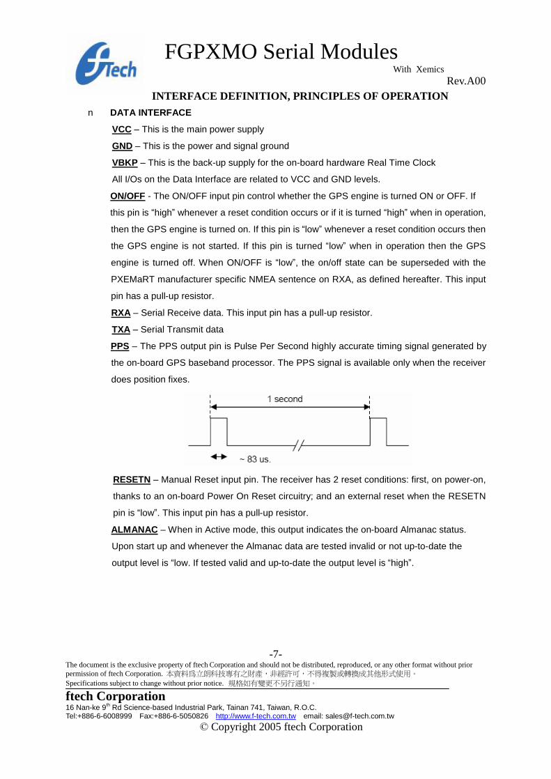
PPS – The PPS output pin is Pulse Per Second highly accurate timing signal generated by
the on-board GPS baseband processor. The PPS signal is available only when the receiver
does position fixes.
RESETN – Manual Reset input pin. The receiver has 2 reset conditions: first, on power-on,
thanks to an on-board Power On Reset circuitry; and an external reset when the RESETN
pin is “low”. This input pin has a pull-up resistor.
ALMANAC – When in Active mode, this output indicates the on-board Almanac status.
Upon start up and whenever the Almanac data are tested invalid or not up-to-date the
output level is “low. If tested valid and up-to-date the output level is “high”.

FGPXMO Serial Modules With Xemics Rev.A00
-8- The document is the exclusive property of ftech Corporation and should not be distributed, reproduced, or any other format without prior permission of ftech Corporation. 本資料為立朗科技專有之財產,非經許可,不得複製或轉換成其他形式使用。 Specifications subject to change without prior notice. 規格如有變更不另行通知。
ftech Corporation 16 Nan-ke 9th Rd Science-based Industrial Park, Tainan 741, Taiwan, R.O.C. Tel:+886-6-6008999 Fax:+886-6-5050826 http://www.f-tech.com.tw email: [email protected]
© Copyright 2005 ftech Corporation
NMEA STANDARD MESSAGE SET SPECIFICATION The FGPXMO Serial Modules support NMEA-0183 v3.01. Brief descriptions of the output
messages are provided herein.
n NMEA Standard Sentences
FGPXMO Serial receivers use the standard output messages listed in Table 1:
NMEA Message Description GGA Global positioning system fixed data GLL Geographic position – latitude/longitude GSA GNSS DOP and active satellites GSV GNSS satellites in view RMC Recommended minimum specific GNSS data VTG Course over ground and ground speed ZDA Time & Date
Table 1. NMEA-0183 Messages After a reset condition occurs, as defined above, the default setting for NMEA sentences is
GGA, GSA, GSV and RMC. This default setting can be modified in the Default Parameters Table
(parameters #3 to #9) in Flash, and can also be overridden with the PXEMaNM manufacturer
specific sentence defined hereafter.
GGA —Global Positioning System Fixed Data
Description: This message reports the global positioning system fixed data, as shown in Table 2.
Name Example Units Description Message ID $GPGGA GGA protocol header UTC Position 161229.4 hhmmss.s Latitude 3723.24753 ddmm.mmmmm N/S Indicator N N = north or S = south Longitude 12158.34165 dddmm.mmmmm E/W Indicator W E = east or W = west Position Fix Indicator 1 See Table3 Satellites Used 07 Range 0 to 12 HDOP 1.02 Horizontal Dilution of Precision MSL Altitude* 00017 Meters MSL: Mean Sea Level Units M Meters Geoid Separation* 017 Meters Units M Meters Age of Diff. Corr. Second Null fields when DGPS is not used Checksum *56 <CR><LF> End of message termination
*Does not support geoid corrections. Values are WGS-84 ellipsoid heights
Table 2. GGA Data Format

FGPXMO Serial Modules With Xemics Rev.A00
-9- The document is the exclusive property of ftech Corporation and should not be distributed, reproduced, or any other format without prior permission of ftech Corporation. 本資料為立朗科技專有之財產,非經許可,不得複製或轉換成其他形式使用。 Specifications subject to change without prior notice. 規格如有變更不另行通知。
ftech Corporation 16 Nan-ke 9th Rd Science-based Industrial Park, Tainan 741, Taiwan, R.O.C. Tel:+886-6-6008999 Fax:+886-6-5050826 http://www.f-tech.com.tw email: [email protected]
© Copyright 2005 ftech Corporation
Value Description 0 Fix not available or invalid 1 GPS SPS Mode, fix valid 2 Differential GPS, SPS Mode, fix valid 3 GPS PPS Mode, fix valid
Table 3. Position Fix Indicator
Example: The values reported in this example are interpreted as shown in Table 2:
$GPGGA,161229.4,3723.24753,N,12158.34165,W,1,07,1.02,00017,M,017,M,,*49 GLL—Geographic Position - Latitude/Longitude
Description: This message reports latitude and longitude geographic positioning data, as described in
Table 4.
Name Example Description Message ID $GPGLL GLL protocol header Latitude 3723.24758 dd mm.mmmmm N/S Indicator N N = north or S = south Longitude 12158.34163 ddd mm.mmmmm E/W Indicator W E = east or W = west UTC Position 161229.4 hh mm ss.s Status A A = data valid or V = data not valid Checksum A*55 A = autonomous, D = differential, E
= estimated, M = manual input, S=simulator mode, N = not valid
<CR><LF> End of message termination Table 4. GLL Data Format
Example: The values reported in this example are interpreted as shown in Table 4:
$GPGLL,3723.24758,N,12158.34163,W,161229.4,A,A*45
GSA—GNSS DOP and Active Satellites
Description: This message reports the satellites used in the navigation solution reported by the GGA
message. GSA is described in Table 5.
Name Example Description Message ID $GPGSA GSA protocol header Mode 1 A See Table 6 Mode 2 3 See Table 7 Satellite Used* 07 SV on Channel 1 Satellite Used* 02 SV on Channel 2 … … Satellite Used* SV on Channel N PDOP 1.83 Position Dilution of Precision HDOP 1.03 Horizontal Dilution of Precision

FGPXMO Serial Modules With Xemics Rev.A00
-10- The document is the exclusive property of ftech Corporation and should not be distributed, reproduced, or any other format without prior permission of ftech Corporation. 本資料為立朗科技專有之財產,非經許可,不得複製或轉換成其他形式使用。 Specifications subject to change without prior notice. 規格如有變更不另行通知。
ftech Corporation 16 Nan-ke 9th Rd Science-based Industrial Park, Tainan 741, Taiwan, R.O.C. Tel:+886-6-6008999 Fax:+886-6-5050826 http://www.f-tech.com.tw email: [email protected]
© Copyright 2005 ftech Corporation
VDOP 1.53 Vertical Dilution of Precision Checksum *33 <CR><LF> End of message termination
*Satellite used in solution.
Table 5. GSA Data Format
Value Description M Manual – forced to operate in 2D or 3D mode A Automatic – allowed to automatically switch 2D/3D
Table 6. Mode 1
Value Description 1 Fix not available 2 2D 3 3D
Table 7. Mode 2
Example: The values reported in this example are interpreted as shown in Table 5:
$GPGSA,A,3,07,02,26,27,09,04,15, , , , , ,1.83,1.03,1.53*20 GSV—GNSS Satellites in View
Description: This message reports the satellites in view, their ID numbers, elevation, azimuth, and SNR
values (up to four satellites per message). GSV is described in Table 8.
Name Example Units Description Message ID $GPGSV GSV protocol header Number of Messages* 2 Range 1 to 3 Message Number* 1 Range 1 to 3 Satellites in View 07 Satellite ID 07 Channel 1 (Range 1 to 32) Elevation 79 degrees Channel 1 (Maximum 90) Azimuth 048 degrees Channel 1 (True, Range 0 to 359) SNR (C/No) 42 dBHz Range 0 to 99, null when not tracking … … Satellite ID 27 Channel 4 (Range 1 to 32) Elevation 27 degrees Channel 4 (Maximum 90) Azimuth 138 degrees Channel 4 (True, Range 0 to 359) SNR (C/No) 42 dBHz Range 0 to 99, null when not tracking Checksum *71 <CR><LF> End of message termination
*Depending on the number of satellites tracked multiple messages of GSV data may be required.
Table 8. GSV Data Format

FGPXMO Serial Modules With Xemics Rev.A00
-11- The document is the exclusive property of ftech Corporation and should not be distributed, reproduced, or any other format without prior permission of ftech Corporation. 本資料為立朗科技專有之財產,非經許可,不得複製或轉換成其他形式使用。 Specifications subject to change without prior notice. 規格如有變更不另行通知。
ftech Corporation 16 Nan-ke 9th Rd Science-based Industrial Park, Tainan 741, Taiwan, R.O.C. Tel:+886-6-6008999 Fax:+886-6-5050826 http://www.f-tech.com.tw email: [email protected]
© Copyright 2005 ftech Corporation
Example: The values reported in this example are interpreted as shown in Table 8. Two messages are
required to complete the data transmission.
$GPGSV,2,1,07,07,79,048,42,02,51,062,43,26,36,256,42,27,27,138,42*71 $GPGSV,2,2,07,09,23,313,42,04,19,159,41,15,12,041,42,10,20,147,39*7A
RMC—Recommended Minimum Specific GNSS Data
Description: This message reports the time, date, position, course, and speed from the receiver’s
navigation solution. RMC is described in Table 9.
Name Example Units Description Message ID $GPRMC RMC protocol header UTC Position 161229.4 Hh mm ss.s Status A A = data valid or V = data not valid Latitude 3723.24758 Dd mm.mmmmm N/S Indicator N N = north or S = south Longitude 12158.34165 Ddd mm.mmmmm E/W Indicator W E = east or W = west Speed Over Ground 000.0 knots Course Over Ground 016.9 degrees True Date 120598 Dd mm yy Magnetic Variation* 02.6 degrees E/W Indicator W E = east or W = west Checksum A*10 A = autonomous, D = differential, E =
estimated, M = manual input, S=simulator mode, N = not valid
<CR><LF> End of message termination *All "course over ground" data are geodetic WGS84 directions.
Table 9. RMC Data Format
Example: The values reported in this example are interpreted as shown in Table 9:
$GPRMC,161229.4,A,3723.24758,N,12158.34165,W,000.0,016.9,120598, 02.6,W,A*10 VTG—Course Over Ground and Ground Speed
Description: This message reports current ground course and speed data. Course is reported relative
to true north only.The VTG message is defined in Table 10.

FGPXMO Serial Modules With Xemics Rev.A00
-12- The document is the exclusive property of ftech Corporation and should not be distributed, reproduced, or any other format without prior permission of ftech Corporation. 本資料為立朗科技專有之財產,非經許可,不得複製或轉換成其他形式使用。 Specifications subject to change without prior notice. 規格如有變更不另行通知。
ftech Corporation 16 Nan-ke 9th Rd Science-based Industrial Park, Tainan 741, Taiwan, R.O.C. Tel:+886-6-6008999 Fax:+886-6-5050826 http://www.f-tech.com.tw email: [email protected]
© Copyright 2005 ftech Corporation
Name Example Units Description Message ID $GPVTG VTG protocol header Course 309.6 degrees Measured heading Reference T True Course 139.6 degrees Measured heading Reference M Magnetic* Speed 000.0 knots Measured horizontal speed Units N Knots Speed 000.2 km/hr Measured horizontal speed Units K Kilometer per hour Checksum A*6E A = autonomous, D = differential, E =
estimated, M = manual input, S=simulator mode, N = not valid
<C R><LF> End of message termination *All "course over ground" data are geodetic WGS84.
Table 10. VTG Data Format
Example: The values reported in this example are interpreted as shown in Table 10:
$GPVTG,309.6,T,139.6,M,000.0,N,000.2,K,A*20
ZDA—Time & Date
Description: This message reports current time and date. The ZDA message is defined in Table 11.
Name Example Units Description Message ID $GPZDA ZDA protocol header Hour, Min, Sec, Sub Sec 114523.6 hhmmss.s Day 12 day in UTC, 01 to 31 Month 04 month in UTC, 01 to 12 Year 2001 year in UTC NULL Checksum *56 <CR><LF> End of message termination
Table 11 ZDA Data Format
Example: The values reported in this example are interpreted as shown in Table 11:
$GPZDA,114523.6,12,04,2001,,*54
FGPXMO Serial Modules With Xemics Rev.A00
-13- The document is the exclusive property of ftech Corporation and should not be distributed, reproduced, or any other format without prior permission of ftech Corporation. 本資料為立朗科技專有之財產,非經許可,不得複製或轉換成其他形式使用。 Specifications subject to change without prior notice. 規格如有變更不另行通知。
ftech Corporation 16 Nan-ke 9th Rd Science-based Industrial Park, Tainan 741, Taiwan, R.O.C. Tel:+886-6-6008999 Fax:+886-6-5050826 http://www.f-tech.com.tw email: [email protected]
© Copyright 2005 ftech Corporation
NMEA SPECIFIC SENTENCES
The NMEA 0183 Standard dictates that proprietary NMEA sentences have the following structure:
$Paaaxxxxxxxxxxxxx*hh
where aaa – mnemonic code, XEM in our case; xxxxxxxxx…– data; hh – sentence checksum
Two types of input sentences are defined: query and set. Query sentences request certain information
from the receiver. Set sentences allow configuring the receiver with certain configuration parameters or
forcing the receiver to perform a specific action. For each type of input sentences, a corresponding
output response sentence is defined. For a query sentence, the response sentence contains requested
data. For a set sentence, the response sentence contains the status of the action requested in the set
sentence. Taking these aspects into account, the following is the general structure of the specific
NMEA sentence:
$PXEMmaa,x1,x2,x3,x4,….,xN*hh
where m – sentence type: ‘Q’ for ‘query’, ‘S’ for ‘set’, ‘R’ for ‘response’; aa – proprietary sentence
identifier (see below);
x1…xN – data parameters (only for set and query response sentences); hh – sentence checksum
NOTE: Each of the data parameters must be preceded with a comma, except for the aa sentence
identifier, and the checksum which is preceded with a checksum delimiter character ‘*’.
• QUERY sentence: to send a query sentence, no data fields are transmitted. The following format is
used:
$PXEMQaa*hh
• RESPONSE sentence to QUERY: for a query sentence, a response sentence with all fields is
transmitted. The following format is used:
$PXEMRaa,x1,x2,x3,x4,….,xN*hh

FGPXMO Serial Modules With Xemics Rev.A00
-14- The document is the exclusive property of ftech Corporation and should not be distributed, reproduced, or any other format without prior permission of ftech Corporation. 本資料為立朗科技專有之財產,非經許可,不得複製或轉換成其他形式使用。 Specifications subject to change without prior notice. 規格如有變更不另行通知。
ftech Corporation 16 Nan-ke 9th Rd Science-based Industrial Park, Tainan 741, Taiwan, R.O.C. Tel:+886-6-6008999 Fax:+886-6-5050826 http://www.f-tech.com.tw email: [email protected]
© Copyright 2005 ftech Corporation
• SET sentence: to send a set sentence, x1…xN must contain valid values. The following format is
used:
$PXEMSaa,x1,x2,x3,x4,….,xN*hh
• RESPONSE sentence to SET: for a set sentence, a status response sentence is transmitted. The
following format is used:
$PXEMRaa,s*hh
where s is the status of the requested action: ‘A’ if the action was successful; ‘V’ otherwise.
The following proprietary NMEA sentence identifiers are implemented:
DI – Diagnostic Message
This sentence outputs a diagnostic string. It is used to report various error conditions. This is a
response-only sentence.
$PXEMRDI,ccccccc*hh where ccccccc is a diagnostic string up to 50 characters
NM – Sentence Mask and Automatic Output Rate
This sentence configures the application to automatically output standard NMEA sentences at a
specified time interval.
$PXEMaNM,xxxx,xx*hh
Name Example Units Description
Message ID $PXEMaNM Proprietary NM protocol header, a-mode (S = set; R = response)
Mask 0008 xxxx Output sentence mask, hex value (see Notes below)
Rate 01 sec xx Automatic output sentence rate (00 to 99)
<CR><LF> End of message termination
Table 13 NM Data Format

FGPXMO Serial Modules With Xemics Rev.A00
-15- The document is the exclusive property of ftech Corporation and should not be distributed, reproduced, or any other format without prior permission of ftech Corporation. 本資料為立朗科技專有之財產,非經許可,不得複製或轉換成其他形式使用。 Specifications subject to change without prior notice. 規格如有變更不另行通知。
ftech Corporation 16 Nan-ke 9th Rd Science-based Industrial Park, Tainan 741, Taiwan, R.O.C. Tel:+886-6-6008999 Fax:+886-6-5050826 http://www.f-tech.com.tw email: [email protected]
© Copyright 2005 ftech Corporation
Notes: xxxx is a hexadecimal value representing a 2-byte bit-mask where a
specific bit sets or clears automatic output of a particular NMEA sentence according to the table below.
The mask is derived by combining all bits which represent the NMEA sentences which will be
automatically output. For example, to automatically output GGA, GSA, ZDA, and RMC, the bits 0, 4, 5,
and 8 are set to 1 in a 2-byte mask, resulting in a hex value 0x131 (0x1+0x10+0x20+0x100). This value
is sent as an ASCII string ‘0131’ in the xxxx field of the NM sentence.
NMEA xxxx
Sentence Bit# Field value
GGA 0 0001
GLL 1 0002
VTG 2 0004
GSV 3 0008
GSA 4 0010
ZDA 5 0020
RMC 8 0100
TF 9 0200
Table 14 Possible MASK field values for the NM command
Example:
$PXEMSNM,0008,01*59 (set) $PXEMRNM,a*1C (response to set: a – action status: A = success; V = failure)
PS – Pulse-Per-Second Configuration
This sentence sets the pulse-per-second (PPS) output on or off. This is a set-only sentence.
$PXEMaPS,x*hh
Name Example Units Description
Message ID $PXEMaPS Proprietary PS protocol header, a-mode (S = se t; R = response)
On/Off 1 PPS output switch (1 = ON; 0 = OFF)
<CR><LF> End of message termination
Table 15 PS Data Format
FGPXMO Serial Modules With Xemics Rev.A00
-16- The document is the exclusive property of ftech Corporation and should not be distributed, reproduced, or any other format without prior permission of ftech Corporation. 本資料為立朗科技專有之財產,非經許可,不得複製或轉換成其他形式使用。 Specifications subject to change without prior notice. 規格如有變更不另行通知。
ftech Corporation 16 Nan-ke 9th Rd Science-based Industrial Park, Tainan 741, Taiwan, R.O.C. Tel:+886-6-6008999 Fax:+886-6-5050826 http://www.f-tech.com.tw email: [email protected]
© Copyright 2005 ftech Corporation
Example:
$PXEMSPS,1*4D (set) $PXEMRPS,a*1C (response to set: a – action status: A = success; V = failure)
PT – Port Configuration
This sentence configures the application serial port communication parameters.
$PXEMaPT,xxxxxx,x,a,x*hh
Name Example Units Description
Message ID $PXEMaPT Proprietary PT protocol header, a-mode (S = set; R= response)
Baudrate 009600 xxxxxx Baud rate (057600, 038400, 019200, 009600, 004800,
002400)
Data length 8 x # of data bits (7 or 8)
Parity N Parity (N = None; O = Odd; E = Even)
Stop bit 1 # of stop bits (1 or 2)
<CR><LF> End of message termination
Table 16 PT Data Format
Example:
$PXEMSPT,009600,8,N,1*1F (set) $PXEMRPT,a*1B (response to set: a – action status: A = success; V = failure)
RT – Reset the Receiver / Start-Stop GPS library
This sentence forces the receiver to perform a software reset. It also allows starting up and shutting
down the GPS library without performing a full software reset. This is a set-only sentence.
$PXEMaRT,a*hh
Name Example Units Description

FGPXMO Serial Modules With Xemics Rev.A00
-17- The document is the exclusive property of ftech Corporation and should not be distributed, reproduced, or any other format without prior permission of ftech Corporation. 本資料為立朗科技專有之財產,非經許可,不得複製或轉換成其他形式使用。 Specifications subject to change without prior notice. 規格如有變更不另行通知。
ftech Corporation 16 Nan-ke 9th Rd Science-based Industrial Park, Tainan 741, Taiwan, R.O.C. Tel:+886-6-6008999 Fax:+886-6-5050826 http://www.f-tech.com.tw email: [email protected]
© Copyright 2005 ftech Corporation
Message ID $PXEMaRT Proprietary RT protocol header, a-mode (S = set; R = response)
Command S C = cold software reset
W = warm software reset
H = hot software reset
S = start the GPS library
X = shut down the GPS library
<CR><LF> End of message termination
Table 17 RT Data Format
Example:
$PXEMSRT,W*2E (set) $PXEMRRT,a*19 (response to set: a – action status: A = success; V = failure)
VR – Version Information
This sentence obtains software versions for the measurement platform (MPM) firmware, GPS API,
GPS Library, native RTOS, and native processor (CPU). This is a query-only sentence.
Note: A complete VR sentence returns only the version of a particular product component one at a time
(either MPM firmware, API, library, RTOS or CPU). The sentence must include the component type for
which to obtain the version for any given query.
$PXEMaVR,a,cccccc,xx,xx,xx,xx,xx,xxxx*hh
Name Example Units Description
Message ID $PXEMaVR Proprietary RT protocol header, a-mode (Q = query; R =
response)
Component type A M = measurement platform (MPM) firmware
A = GPS API
N = GPS Library
R = native RTOS
U = native processor (CPU)
V = Software build
Name abcdef variable length field; may be up to 17 characters long
Maj version 04 Major version number (00 to 99)
FGPXMO Serial Modules With Xemics Rev.A00
-18- The document is the exclusive property of ftech Corporation and should not be distributed, reproduced, or any other format without prior permission of ftech Corporation. 本資料為立朗科技專有之財產,非經許可,不得複製或轉換成其他形式使用。 Specifications subject to change without prior notice. 規格如有變更不另行通知。
ftech Corporation 16 Nan-ke 9th Rd Science-based Industrial Park, Tainan 741, Taiwan, R.O.C. Tel:+886-6-6008999 Fax:+886-6-5050826 http://www.f-tech.com.tw email: [email protected]
© Copyright 2005 ftech Corporation
Min version 02 Minor version number (00 to 99)
Beta version 03 Beta version number (00 to 99)
Month 10 Month of the release (01 to 12)
Day 27 Day of the release (01 to 31)
Year 2002 Year of the release
<CR><LF> End of message termination
Table 18 VR Data Format
Example:
$PXEMQVR,R*2B (query) $PXEMRVR,R,nucleus,04,03,03,10,27,2000*71 (response to query)
GS – Geodetic System Configuration
This sentence sets the geodetic system use to compute the geographic positioning data.
$PXEMaGS,ee,xxxx.xxxxxx,yyyy.yyyyyy,zzzz.zzzzzz*hh
Name Example Units Description
Message ID $PXEMaGS Proprietary GS protocol header, a-mode (S = set; R =
response)
Ellipsoid 12 ee Ellipsoid Model (see table below)
Delta X -0.148 m xxxx.xxxxxx, shift parameter on x axis
Delta Y 0.096 m yyyy.yyyyyy, shift parameter on y axis
Delta Z 0.122 m zzzz.zzzzzz, shift parameter on z axis
<CR><LF> End of message termination
Table 19 GS Data Format
Index Ellipsoid Name Semi-Major Axis Flattening

FGPXMO Serial Modules With Xemics Rev.A00
-19- The document is the exclusive property of ftech Corporation and should not be distributed, reproduced, or any other format without prior permission of ftech Corporation. 本資料為立朗科技專有之財產,非經許可,不得複製或轉換成其他形式使用。 Specifications subject to change without prior notice. 規格如有變更不另行通知。
ftech Corporation 16 Nan-ke 9th Rd Science-based Industrial Park, Tainan 741, Taiwan, R.O.C. Tel:+886-6-6008999 Fax:+886-6-5050826 http://www.f-tech.com.tw email: [email protected]
© Copyright 2005 ftech Corporation
00 Airy 1830 6377563.396 299.3249646
01 Australian National & South American 1969 6378160 298.25
02 Bessel 1841 Ethiopia 6377397.155 299.1528128
03 Bessel1841 Namibia 6377483.865 299.1528128
04 Clarke 1866 6378206.4 294.9786982
05 Clarke 1880 6378249.145 293.465
06 Everest Brunei and E. Malaysia 6377298.556 300.8017
07 Everest India 1830 6377276.345 300.8017
08 Everest India 1956 6377301.243 300.8017
09 Everest Pakistan 6377309.613 300.8017
10 Everest W. Malaysia and Singapore 1948 6377304.063 300.8017
11 Geodetic Reference System 1980 6378137 298.257222101
12 Helmert 1906 6378200 298.3
13 Hough 1960 6378270 297
14 Indonesian 1974 6378160 298.247
15 International 1924 & Hayford 6378388 297
16 Krassovsky 1940 6378245 298.3
17 Modified Airy 6377340.189 299.3249646
18 Modified Fischer 1960 6378155 298.3
19 WGS 1972 6378135 298.26
20 WGS 1984 6378137 298.257223563
Table 20 Ellipsoid models
Example:
$PXEMSGS,12,-0.148,0.096,0.122*44 (set) $PXEMRGS,a,12,-0.148,0.096,0.122*08 (response to set: a – action status: A = success; V = failure)
see also Exhibit B for further examples
LP – Power Save Mode
This sentence sets the receiver in Power Save mode. To go back to the Active mode, users should
send any valid NMEA sentence to the receiver. Do not toggle the ON/OFF pin to go to the Active Mode

FGPXMO Serial Modules With Xemics Rev.A00
-20- The document is the exclusive property of ftech Corporation and should not be distributed, reproduced, or any other format without prior permission of ftech Corporation. 本資料為立朗科技專有之財產,非經許可,不得複製或轉換成其他形式使用。 Specifications subject to change without prior notice. 規格如有變更不另行通知。
ftech Corporation 16 Nan-ke 9th Rd Science-based Industrial Park, Tainan 741, Taiwan, R.O.C. Tel:+886-6-6008999 Fax:+886-6-5050826 http://www.f-tech.com.tw email: [email protected]
© Copyright 2005 ftech Corporation
if a NMEA LP command is used to switch to the Power Save mode
$PXEMaLP*hh
Name Example Units Description
Message ID $PXEMaLP Proprietary LP protocol header, a-mode (S = set; R =
response)
<CR><LF> End of message termination
Table 21 LP Data format
Example:
$PXEMSLP*4F (set) $PXEMRLP,a*3 (response to set: a – action status: A = success; V = failure)
TR –Transparent Mode
With this type of sentence, an API function call is passed thru the NMEA interface. This can be a query,
set, and response type of sentence.
The most useful TR types of proprietary NMEA sentences are listed below.
Set the RTC time
The purpose of GPS time is to allow use of the almanac data and position to determine which satellites
are in view and to allow rough ranging to the satellites. FGPXMOxxx products load GPS time every
start-up. If the local RTC, from which this GPS time is loaded, is not valid it is possible to provide the
GPS time from another source. The accuracy of this external source should be better than 30 minutes.
The time/date information in the GPS system is coded using a standard GPS time format that is a week
number and the time of the week. The week number of the GPS time is the number of weeks from
Sunday, January 6 1980. However, due to the GPS data message format, the week number is a
modulo-1024 number (10-bit number). The last rollover occurred on August 22, 1999. The next rollover
will happen on April 7, 2019. The GPS time of the week is the number of milliseconds since the
beginning of the current GPS week, the GPS week starting on Sundays at 0 hour, 0 minute, 0
millisecond. When the GPS engine is running the TR sentence to use is:

FGPXMO Serial Modules With Xemics Rev.A00
-21- The document is the exclusive property of ftech Corporation and should not be distributed, reproduced, or any other format without prior permission of ftech Corporation. 本資料為立朗科技專有之財產,非經許可,不得複製或轉換成其他形式使用。 Specifications subject to change without prior notice. 規格如有變更不另行通知。
ftech Corporation 16 Nan-ke 9th Rd Science-based Industrial Park, Tainan 741, Taiwan, R.O.C. Tel:+886-6-6008999 Fax:+886-6-5050826 http://www.f-tech.com.tw email: [email protected]
© Copyright 2005 ftech Corporation
$PXEMSTR,SSIT,WeekNb,TimeOfWeek,Accu*hh
where:
• WeekNb is the week number (see above)
• TimeOfWeek is the time of the week information, in milliseconds (see above)
• Accu reflects the accuracy of the time information provided to the system. Use 1 only if the time of the
week and the week number are valid (accuracy better than 30 minutes), otherwise -1
Important notes: if the Accu parameter is set to 1, the hardware RTC will be updated when receiving
this command. However, if the Accu parameter is set to -1, the hardware RTC will NOT be updated
when receiving the sentence. Also, it is strongly advised to avoid setting the Accu parameter to 1 if one
is not sure about the accuracy, as this may lead to improper behavior.
Set the initial position
The purpose of the rough initial position is to allow use of the almanac data and GPS time to determine
which satellites are in view. This is achieved by sending a proprietary TR command which format is:
$PXEMSTR,SSIP,L.LLL,O.OOO,Alt,Accu*hh
where:
• L.LLL is the latitude expressed in radian
• O.OOO is the longitude expressed in radian
• Alt is the altitude expressed in meter. Note that if you are not sure about the altitude, a default value of
200 gives acceptable results in most cases.
• Accu reflects the accuracy of the initial position. Use -1
For example, to set the position to New Delhi in India (coordinates being lat: 0.499, lon: 1.347), the full
sentence should be:
$PXEMSTR,SSIP,0.499,1.347,200,-1*hh

FGPXMO Serial Modules With Xemics Rev.A00
-22- The document is the exclusive property of ftech Corporation and should not be distributed, reproduced, or any other format without prior permission of ftech Corporation. 本資料為立朗科技專有之財產,非經許可,不得複製或轉換成其他形式使用。 Specifications subject to change without prior notice. 規格如有變更不另行通知。
ftech Corporation 16 Nan-ke 9th Rd Science-based Industrial Park, Tainan 741, Taiwan, R.O.C. Tel:+886-6-6008999 Fax:+886-6-5050826 http://www.f-tech.com.tw email: [email protected]
© Copyright 2005 ftech Corporation
The initial position can only be set when the GPS engine is running and before the
system does position fix. Note that an initial position error of 1,000 km will result in an almanac based
satellite search set which has rotated out of view by approximately 10%. Beyond this, the specified
performance will degrade. Initial position errors greater than 3,000 km will result in a constellation which
is almost out of view. So, the recommendation is to set the initial position only if its accuracy is better
than 1,200 km.
Important Note: after the receiver gets this command the content of the GPS data RAM will be saved in
the back-up Flash upon the first position fix.
Delete the initial position
This NMEA sentence has the same effect as the hardware input DELPOSN. It allows deleting the initial
position in the RAM portion of the MCU and triggering re-computation of the tracking set. The position
will not be deleted if GPS fixes are already being generated. This function is useful when the initial
position is known to be incorrect, for example when the receiver is powered down, put on a plane, flown
20,000 km, and then warm-started. The command is:
$PXEMSTR,SSDI*74
Important Note: after the PXEMSTR,SSDI command is sent, the receiver should make a position fix
before it saves GPS data in its back-up Flash memory.
GPS DATA BACK-UP
The almanac data is the information transmitted by each satellite on the orbits and state (health) of the entire
constellation. The ephemeris is a list of accurate positions or locations of celestial objects as a function of time. So,
the availability of almanac and ephemeris data, in addition to time and approximate position, allows the GPS
receiver to rapidly acquire satellites as soon as it is turned on. There are 3 possible start conditions when the
receiver is turned on:
a) the Cold Start, that is the start-up sequence of the receiver when no initialization data is available;
b) the Warm Start, that is the start-up sequence of the receiver when the last position, the time and the almanac
information are available;
c) the Hot Start, that is the start-up sequence of the receiver when the ephemeris, the last position, the time and
the almanac information are available.

FGPXMO Serial Modules With Xemics Rev.A00
-23- The document is the exclusive property of ftech Corporation and should not be distributed, reproduced, or any other format without prior permission of ftech Corporation. 本資料為立朗科技專有之財產,非經許可,不得複製或轉換成其他形式使用。 Specifications subject to change without prior notice. 規格如有變更不另行通知。
ftech Corporation 16 Nan-ke 9th Rd Science-based Industrial Park, Tainan 741, Taiwan, R.O.C. Tel:+886-6-6008999 Fax:+886-6-5050826 http://www.f-tech.com.tw email: [email protected]
© Copyright 2005 ftech Corporation
In the FGPXMO Serial Modules design the GPS data structure, including almanac, ephemeris and last
position fix, is copied into a specific sector of the on-board Flash memory, that’s the back-up Flash sector, or
BBFlash. The data are stored the first time the almanac is complete and up-to-date, then every M minutes, where
M is defined in Default Parameters Table *, parameter #37. Alternatively, the Flash can be programmed with
valid information during the manufacturing process. This is to avoid downloading it from satellites, which takes
approx. 12.5 minutes. Then, as long as the main power supply remains turned On, the GPS data structure is kept
in RAM. However, data in RAM are not maintained if the main supply is switched Off (or in case of a power failure).
In this case, upon power up, these data are uploaded from the Flash back-up memory into the GPS data RAM.
Provided these data are valid – 2 months for the Almanac, 2 hours for ephemeris – the TTFF will be shorter
than Cold Start TTFF, since the receiver will be in Warm or Hot start condition.
REAL TIME CLOCK
The receiver board has a hardware Real Time Clock chip that operates independently from the MCU and the GPS
function. When the GPS receiver is active and as soon as the GPS time becomes available the RTC is
synchronized with GPS time. Then, as long as GPS time is available, the RTC is synchronized every 60 minutes.
If the main power supply VCC is turned OFF and provided the VBKP supply is available, the RTC operates and
keep RTC information up to date. By doing so, when both the main VCC supply and the GPS receiver are turned
ON again the time information will be available.
SPLIT SEARCH MODE
This feature is useful when the initial position is incorrect, for example when the receiver is
powered down, put on a plane, flown 10,000 km, and then warm-started. If the user does not activate
the DELPOSN I/O on (Pin Not available on this module ) or does not sent the proprietary
PXEMSTR,SSDI NMEA command, the receiver will start to search for the satellites it believes are
above it (warm start condition). However, after approximately 5 minutes, it will free up some of its
channels to search for other satellites in the constellation. When it finds one it will free up more
channels and recover from a Warm start with an inaccurate initial position.
DEFAULT SETTINGS A number of system settings are stored in a particular area of the embedded Flash. That’s the Default
Parameters Table, whose content is listed hereafter. Some of these settings can be modified by
sending a proprietary NMEA sentence to the receiver, as defined above.

FGPXMO Serial Modules With Xemics Rev.A00
-24- The document is the exclusive property of ftech Corporation and should not be distributed, reproduced, or any other format without prior permission of ftech Corporation. 本資料為立朗科技專有之財產,非經許可,不得複製或轉換成其他形式使用。 Specifications subject to change without prior notice. 規格如有變更不另行通知。
ftech Corporation 16 Nan-ke 9th Rd Science-based Industrial Park, Tainan 741, Taiwan, R.O.C. Tel:+886-6-6008999 Fax:+886-6-5050826 http://www.f-tech.com.tw email: [email protected]
© Copyright 2005 ftech Corporation
# Default parameter Data Type Default value Range values 1 PPS Output Enabled Char Y Y / N 2 NMEA refresh rate Integer 1 second 1 to 99 seconds 3 NMEA GGA output displ’d Char Y Y / N 4 NMEA GLL output displ’d Char N Y / N 5 NMEA VTG output displ’d Char N Y / N 6 NMEA GSV output displ’d Char Y Y / N 7 NMEA GSA output displ’d Char Y Y / N 8 NMEA ZDA output displ’d Char N Y / N 9 NMEA RMC output displ’d Char Y Y / N 10 NMEA TF output displ’d Char N Y / N 11 NMEA GGA display order Integer 2 1 .. 8 12 NMEA GLL display order Integer 5 1 .. 8 13 NMEA VTG display order Integer 6 1 .. 8 14 NMEA GSV display order Integer 4 1 .. 8 15 NMEA GSA display order Integer 1 1 .. 8 16 NMEA ZDA display order Integer 7 1 .. 8 17 NMEA RMC display order Integer 3 1 .. 8 18 NMEA TF display order Integer 8 1 .. 8 19 Serial Port A Baudrate Integer 4800 2400 / 4800 / 9600 / 19200 / 38400 / 57600 20 Serial Port A Data bits Integer 8 7 .. 8 21 Serial Port A Stop bits Integer 1 1 .. 2 22 Serial Port A Parity bits Character N N / O / E 23 Serial Port B Baudrate Integer 9600 2400 / 4800 / 9600 / 19200 / 38400 / 57600 24 Serial Port B Data bits Integer 8 7 .. 8 25 Serial Port B Stop bits Integer 1 1 .. 2 26 Serial Port B Parity bits Character N N / O / E 27 Dynamic Code Integer 5 1 – Land
2 – Sea 3 – Air 4 – Stationary 5 - Automobile
28 Max Oscillator Offset Real 7.9e-6 Depends on the Oscillator 29 Elevation Mask Real 5 0 to 10 degrees 30 Signal Level Mask (AMU) Real 1.8 1 to 6 31 DOP Mask Real 12 6 to 20 32 PDOP Switch Real 8 6 to 8 33 Geodetic System Ellipsoid Integer 20 0 to 20 34 Geodetic System Delta X Real 0 -9999.99999 to +9999.99999 35 Geodetic System Delta Y Real 0 -9999.99999 to +9999.99999 36 Geodetic System Delta Z Real 0 -9999.99999 to +9999.99999 37 BBFlash Update rate
(minutes) 32 bits Integer
10 - v 2.2 - 16MB Flash option
1 to (2**32)-1

FGPXMO Serial Modules With Xemics Rev.A00
-25- The document is the exclusive property of ftech Corporation and should not be distributed, reproduced, or any other format without prior permission of ftech Corporation. 本資料為立朗科技專有之財產,非經許可,不得複製或轉換成其他形式使用。 Specifications subject to change without prior notice. 規格如有變更不另行通知。
ftech Corporation 16 Nan-ke 9th Rd Science-based Industrial Park, Tainan 741, Taiwan, R.O.C. Tel:+886-6-6008999 Fax:+886-6-5050826 http://www.f-tech.com.tw email: [email protected]
© Copyright 2005 ftech Corporation
GPS ENGINE CONFIGURATION
In addition, there are some settings for the embedded GPS library that cannot be modified by the users
Receiver configuration
DGPS Mode DGPS Off
Filter configuration
Kalman Filter
Offset configuration
Offset 0 ppm
Window -1 ppm
Application settings
Number of channels 8
Week epoch 1024 the offset number of 1024 week periods since 6
January 1980. Setting to 1024 includes all dates
between August 22, 1999 and March 2019.

FGPXMO Serial Modules With Xemics Rev.A00
-26- The document is the exclusive property of ftech Corporation and should not be distributed, reproduced, or any other format without prior permission of ftech Corporation. 本資料為立朗科技專有之財產,非經許可,不得複製或轉換成其他形式使用。 Specifications subject to change without prior notice. 規格如有變更不另行通知。
ftech Corporation 16 Nan-ke 9th Rd Science-based Industrial Park, Tainan 741, Taiwan, R.O.C. Tel:+886-6-6008999 Fax:+886-6-5050826 http://www.f-tech.com.tw email: [email protected]
© Copyright 2005 ftech Corporation
Exhibit A – Physical Dimensions Shield cover Dimension

FGPXMO Serial Modules With Xemics Rev.A00
-27- The document is the exclusive property of ftech Corporation and should not be distributed, reproduced, or any other format without prior permission of ftech Corporation. 本資料為立朗科技專有之財產,非經許可,不得複製或轉換成其他形式使用。 Specifications subject to change without prior notice. 規格如有變更不另行通知。
ftech Corporation 16 Nan-ke 9th Rd Science-based Industrial Park, Tainan 741, Taiwan, R.O.C. Tel:+886-6-6008999 Fax:+886-6-5050826 http://www.f-tech.com.tw email: [email protected]
© Copyright 2005 ftech Corporation
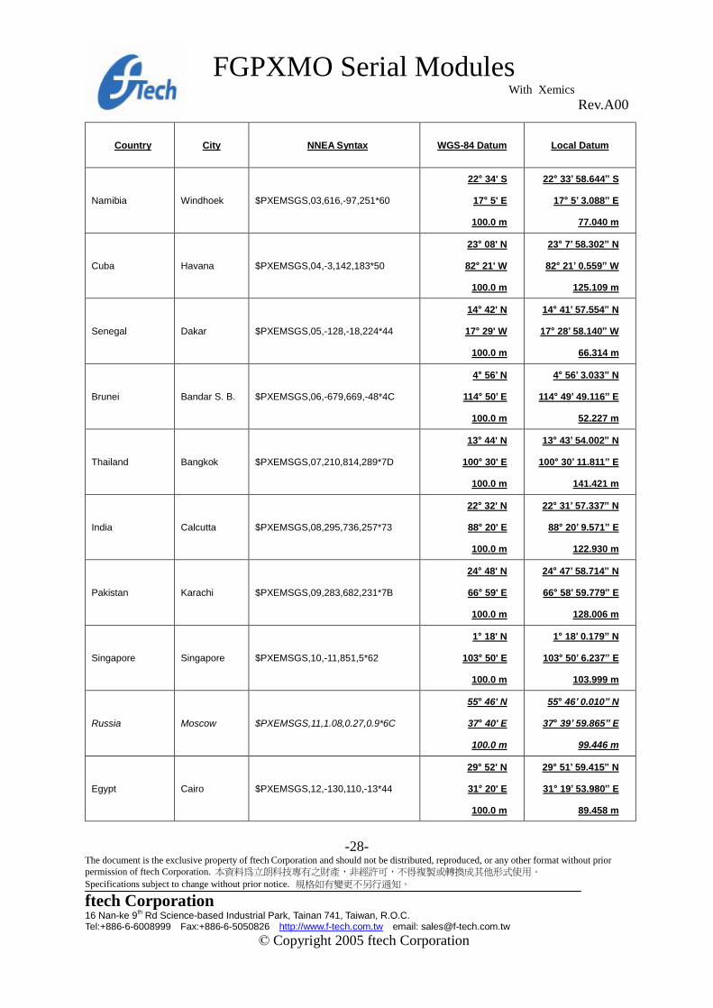
Pin header Dimension Exhibit B-
The following table illustrates datums for some cities around the world.
Country City NNEA Syntax WGS-84 Datum Local Datum
Wales Cardiff $PXEMSGS,00,375,-111,431*5C
51° 23’ N
3° 20’ W
100.0 m
51° 22’ 58.454” N
3° 19’ 55.396” W
51.497 m
Australia Sydney $PXEMSGS,01,-134,-48,149*40
33° 52' S
151° 12' E
100.0 m
33° 52’ 5.738” S
151° 11’ 55.851” E
81.918 m
Japan Tokyo $PXEMSGS,02,-148,507,685*5C
35° 41' N
139° 46' E
100.0 m
35° 40’ 48.239” N
139° 46’ 11.591” E
59.959 m
FGPXMO Serial Modules With Xemics Rev.A00
-28- The document is the exclusive property of ftech Corporation and should not be distributed, reproduced, or any other format without prior permission of ftech Corporation. 本資料為立朗科技專有之財產,非經許可,不得複製或轉換成其他形式使用。 Specifications subject to change without prior notice. 規格如有變更不另行通知。
ftech Corporation 16 Nan-ke 9th Rd Science-based Industrial Park, Tainan 741, Taiwan, R.O.C. Tel:+886-6-6008999 Fax:+886-6-5050826 http://www.f-tech.com.tw email: [email protected]
© Copyright 2005 ftech Corporation
Country City NNEA Syntax WGS-84 Datum Local Datum
Namibia Windhoek $PXEMSGS,03,616,-97,251*60
22° 34' S
17° 5' E
100.0 m
22° 33’ 58.644” S
17° 5’ 3.088” E
77.040 m
Cuba Havana $PXEMSGS,04,-3,142,183*50
23° 08' N
82° 21' W
100.0 m
23° 7’ 58.302” N
82° 21’ 0.559” W
125.109 m
Senegal Dakar $PXEMSGS,05,-128,-18,224*44
14° 42' N
17° 29' W
100.0 m
14° 41’ 57.554” N
17° 28’ 58.140” W
66.314 m
Brunei Bandar S. B. $PXEMSGS,06,-679,669,-48*4C
4° 56’ N
114° 50’ E
100.0 m
4° 56’ 3.033” N
114° 49’ 49.116” E
52.227 m
Thailand Bangkok $PXEMSGS,07,210,814,289*7D
13° 44' N
100° 30' E
100.0 m
13° 43’ 54.002” N
100° 30’ 11.811” E
141.421 m
India Calcutta $PXEMSGS,08,295,736,257*73
22° 32' N
88° 20' E
100.0 m
22° 31’ 57.337” N
88° 20’ 9.571” E
122.930 m
Pakistan Karachi $PXEMSGS,09,283,682,231*7B
24° 48' N
66° 59' E
100.0 m
24° 47’ 58.714” N
66° 58’ 59.779” E
128.006 m
Singapore Singapore $PXEMSGS,10,-11,851,5*62
1° 18' N
103° 50' E
100.0 m
1° 18’ 0.179” N
103° 50’ 6.237” E
103.999 m
Russia Moscow $PXEMSGS,11,1.08,0.27,0.9*6C
55° 46' N
37° 40' E
100.0 m
55° 46’ 0.010” N
37° 39’ 59.865” E
99.446 m
Egypt Cairo $PXEMSGS,12,-130,110,-13*44
29° 52' N
31° 20' E
100.0 m
29° 51’ 59.415” N
31° 19’ 53.980” E
89.458 m

FGPXMO Serial Modules With Xemics Rev.A00
-29- The document is the exclusive property of ftech Corporation and should not be distributed, reproduced, or any other format without prior permission of ftech Corporation. 本資料為立朗科技專有之財產,非經許可,不得複製或轉換成其他形式使用。 Specifications subject to change without prior notice. 規格如有變更不另行通知。
ftech Corporation 16 Nan-ke 9th Rd Science-based Industrial Park, Tainan 741, Taiwan, R.O.C. Tel:+886-6-6008999 Fax:+886-6-5050826 http://www.f-tech.com.tw email: [email protected]
© Copyright 2005 ftech Corporation
Country City NNEA Syntax WGS-84 Datum Local Datum
Marshall Island Majuro $PXEMSGS,13,102,52,-38*57
41° 32’ N
12° 18’ E
100.0 m
41° 32’ 6.227” N
12° 17’ 58.745” E
-50.775 m
Indonesia Djakarta $PXEMSGS,14,-24,-15,5*75
6° 11' S
106° 50' E
100.0 m
6° 11’ 0.141” S
106° 49’ 59.111” E
84.912 m
France Paris $PXEMSGS,15,-87,-96,-120*5D
48° 49' N
2° 29' E
100.0 m
48° 49’ 3.271” N
2° 29’ 4.516” E
50.964 m
Somalia Mogadiscio $PXEMSGS,16,-43,-163,45*72
2° 2' N
49° 19' E
100.0 m
2° 1’ 58.354” N
49° 19’ 2.383” E
141.943 m
Ireland Dublin $PXEMSGS,17,506,-122,611*58
53° 22' N
6° 21' W
100.0 m
53° 21’ 59.163” N
6° 20’ 56.468” W
47.599 m
Singapore Singapore $PXEMSGS,18,7,-10,26*51
1° 18' N
103° 50' E
100.0 m
1° 18’ 0.833” N
103° 50’ 0.142” E
93.969 m
Ireland Dublin $PXEMSGS,19,0,0,4.5*60
53° 22' N
6° 21' W
100.0 m
53° 21’ 59.906” N
6° 21’ 0.554” W
96.856 m
Ireland Dublin $PXEMSGS,20,0,0,0*75
53° 22' N
6° 21' W
100.0 m
53° 22' N
6° 21' W
100.0 m

FGPXMO Serial Modules With Xemics Rev.A00
-30- The document is the exclusive property of ftech Corporation and should not be distributed, reproduced, or any other format without prior permission of ftech Corporation. 本資料為立朗科技專有之財產,非經許可,不得複製或轉換成其他形式使用。 Specifications subject to change without prior notice. 規格如有變更不另行通知。
ftech Corporation 16 Nan-ke 9th Rd Science-based Industrial Park, Tainan 741, Taiwan, R.O.C. Tel:+886-6-6008999 Fax:+886-6-5050826 http://www.f-tech.com.tw email: [email protected]
© Copyright 2005 ftech Corporation
Exhibit C-Built-In Active antenna information Antenna Specification
Voltage 2.7V 3.3V 5V
Current Consumption 4mA 5~6mA 9mA
Fo 1575.42MHz
Bandwidth 2.046MHz
Operation Temperature
(centigrade)
-40~85°C
Output VSWR 2
Impedance 50W
Patch Antenna
Polarization R.H.C.P.
Gain to Fo 3dBi
Impedance 50W
Pre Amplifier (dB)
Gain to Fo 19dB 21dB 23dB
Noise Figure 2.5dB
Impedance 50W Copyright 2005 by ftech Corporation All rights reserved. Reproduction in whole or in part is prohibited without the prior written consent of the copyright owner. The information presented in this document does not form part of any quotation or contract, is believed to be accurate and reliable and may be changed without notice. No liability will be accepted by the publisher for any consequence of its use. Publication thereof does not convey nor imply any license under patent or other industrial or intellectual property rights. FTECH PRODUCTS ARE NOT DESIGNED, INTENDED, AUTHORIZED OR WARRANTED TO BE SUITABLE FOR USE IN LIFE-SUPPORT APPLICATIONS, DEVICES OR SYSTEMS OR OTHER CRITICAL APPLICATIONS. INCLUSION OF FTECH PRODUCTS IN SUCH APPLICATIONS IS UNDERSTOOD TO BE UNDERTAKEN SOLELY AT THE CUSTOMER’S OWN RISK. Should a customer purchase or use ftech products for any such unauthorized application, the customer shall indemnify and hold ftech and its officers, employees, subsidiaries, affiliates, and distributors harmless against all claims, costs damages and attorney fees which could arise.