
YES 45 XT High Performance Thermal Storefront … 45 XT High Performance Thermal Storefront System...
24
YES 45 XT High Performance Thermal Storefront System Installation Manual ©2010 YKK AP America Inc. is a subsidiary of YKK Corporation of America. ThermaBond Plus ® Pour & Debridge Technology Dual Thermal Barrier
-
Upload
truongdang -
Category
Documents
-
view
216 -
download
0
Transcript of YES 45 XT High Performance Thermal Storefront … 45 XT High Performance Thermal Storefront System...
YES 45 XT High Performance Thermal Storefront System
Installation Manual
©2010 YKK AP America Inc. is a subsidiary of YKK Corporation of America.
ThermaBond Plus®
Pour & DebridgeTechnology
Dual Thermal Barrier


Effective Date: December 1, 2010 | 02-4012-00 Page-i
YES 45 XT High Performance Thermal Storefront System
TABLE OF CONTENTS
Installation Notes . . . . . . . . . . . . . . . . . . . . . . . . . . . . . . . . . . . . . . . . Page ii
PARTS DESCRIPTIONYES 45 XT Framing Members . . . . . . . . . . . . . . . . . . . . . . . . . . . . . . Page 1YES 45 XT Door Framing Members . . . . . . . . . . . . . . . . . . . . . . . . . . Page 2YES 45 XT Accessories . . . . . . . . . . . . . . . . . . . . . . . . . . . . . . . . . . . Page 3
FRAME FABRICATIONDetermine Frame Size . . . . . . . . . . . . . . . . . . . . . . . . . . . . . . . . . . . . Page 4Fabricate Two Piece Verticals . . . . . . . . . . . . . . . . . . . . . . . . . . . . . . Page 5Fabricate Head, Horizontal & Sill Members . . . . . . . . . . . . . . . . . . . . Page 6Fabricate Glass Stops & Glazing Adaptors . . . . . . . . . . . . . . . . . . . . Page 6Fabricate Sill Members . . . . . . . . . . . . . . . . . . . . . . . . . . . . . . . . . . . . Page 6Fabricate Sill Flashing . . . . . . . . . . . . . . . . . . . . . . . . . . . . . . . . . . . . Page 7
FRAME ASSEMBLYAssemble Frames For Screw Spline Assembly . . . . . . . . . . . . . . . . . Page 8
FRAME INSTALLATIONInstall Sill Flashing End Dams . . . . . . . . . . . . . . . . . . . . . . . . . . . . . . Page 9Install Sill Flashing . . . . . . . . . . . . . . . . . . . . . . . . . . . . . . . . . . . . . . . Page 10Install Sill Flashing Splice Sleeve . . . . . . . . . . . . . . . . . . . . . . . . . . . . Page 10 & 11Install Frames . . . . . . . . . . . . . . . . . . . . . . . . . . . . . . . . . . . . . . . . . . . Page 12 & 13Apply Perimeter Sealant . . . . . . . . . . . . . . . . . . . . . . . . . . . . . . . . . . . Page 13Install Water Deflectors . . . . . . . . . . . . . . . . . . . . . . . . . . . . . . . . . . . . Page 14Apply Internal Sealant . . . . . . . . . . . . . . . . . . . . . . . . . . . . . . . . . . . . Page 15Install Glazing Adaptors . . . . . . . . . . . . . . . . . . . . . . . . . . . . . . . . . . . Page 16
GLAZINGInstall Interior Glazing Gaskets . . . . . . . . . . . . . . . . . . . . . . . . . . . . . . Page 16Install Glass . . . . . . . . . . . . . . . . . . . . . . . . . . . . . . . . . . . . . . . . . . . . Page 17Install Anti-Walk Blocks . . . . . . . . . . . . . . . . . . . . . . . . . . . . . . . . . . . . Page 18Install Exterior Glass Stops & Gaskets . . . . . . . . . . . . . . . . . . . . . . . . Page 18

02-4012-00 | Effective Date: December 1, 2010Page-ii
YES 45 XT High Performance Thermal Storefront System
Installation Notes
1. Do not drop, roll or drag boxes of aluminum framing. Move and stack boxes with proper supportto prevent distortion. If fork lifts are used be especially careful about striking the boxes when lifting or moving.
2. Store in a dry, out of the way area. If rain exposure, condensation or any water contact is likely,then all packaging material should be removed. Wet packaging materials will discolor and may stainaluminum finishes and paints.
3. All materials should be checked for quality and quantity upon receipt, YKK AP must be notified immediately of any discrepancies in shipment. Check to make sure that you have the requiredshims, sealants, supplies and tools necessary for the installation.
4. Carefully check the openings and surrounding conditions that will receive your material.Remember, if the construction is not per the construction documents, it is your responsibility to notify the general contractor in writing. Any discrepancies must be brought to the general contractor's attention before you proceed with the installation.
5. Gather your shop drawings, materials, packing list, and this installation manual. Carefully reviewparts location, the sequence it goes therein, when you glaze it and how you seal it. Installationinstructions are of a general nature and may not cover every condition you will encounter. The shopdrawings and/or installation manuals were prepared specifically for the product.
6. Any material substitutions must be of equal or greater quality.
7. Make certain that material samples have been sent for compatibility testing for all manufacturer'ssealants involved. Make certain sealants have been installed in strict accordance with the manufacturer's recommendations and specifications.
8. Remember to isolate, in an approved manner, all aluminum from uncured masonry or otherincompatible materials.
9. System-to-structure fasteners are not supplied by YKK AP. Fasteners called out on shop drawings are to indicate minimum sizes for design loading.
10. Entrances are to be installed plumb, square, level and true.
11. Please contact the YKK AP DirecTech application engineering department for any project specific condition not covered by these instructions.
12. YKK AP storefront and/or curtain wall framing is typically completed before drywall, flooring andother products which may still be in process. Take the extra time to wrap and protect the work thatyou have proudly produced, because no one else will.
13. Cutting tolerances are plus zero (0"), minus one thirty second (-1/32") unless otherwise noted.
14. Check our website, www.ykkap.com, for the latest installation manual update prior to commencing work.

Effective Date: December 1, 2010 | 02-4012-00 Page-1
YES 45 XT High Performance Thermal Storefront System
YES 45 XT FRAMING MEMBERS (2" x 4-1/2")
Vertical / Jamb BE9-2601
Head - Outside Glazing BE9-2602
Horizontal BE9-2603
Sill - Inside & OutsideGlazingHead - Inside Glazing
BE9-2604
Heavy Duty Vertical Mullion
BE9-2606
Sill Flashing BE9-2578
Pocket Filler BE9-2605
Head Receptor Stop E9-1033
Head Receptor BE9-2562
Glass Stop E9-1015
Deep Pocket Filler BE9-2609
Expansion Mullion (Female) BE9-2607
BE9-2608
BE9-2557
BE9-2558
90° Corner Mullion BE9-2566
90° Corner Mullion BE9-2567
3-Way Corner Mullion BE9-2568
135° Corner Mullion BE9-2569
4-1/2" Horizontal/Sill BE9-1513
Expansion Mullion (Male)
Hinged Mullion (Male)
Hinged Mullion (Female)
Glazing AdaptorFor 1/4" glazing
E9-1040

02-4012-00 | Effective Date: December 1, 2010Page-2
YES 45 XT High Performance Thermal Storefront System
THERMAL DOOR FRAMING MEMBERS
NON-THERMAL DOOR FRAMING MEMBERSSingle ActingDoor JambElastomer weatheringE2-0051 included
AS-0411
Single ActingDoor Head/Transom BarElastomer weatheringE2-0051 included
AS-0412
Double ActingDoor Jamb E9-0415
Double ActingDoor Head/Transom BarPile weatheringE2-0062 included
AS-0426
IntermediateDoor Jamb2” x 4-1/2” TubeUse with AS-0401
E9-9312
Deep Pocket FillerUse with door jambs E9-1019
Door Stop AssemblyE9-0409 (mill) & E9-1113Elastomer weatheringE2-0051 included
AS-0401
Transom Glass StopFor 1/4” glazing E9-0403
Transom Glass StopFor 1” glazing E9-0413
Transom Glazing PocketFor 1/4” glazing E9-0434
Single ActingDoor JambElastomer weatheringE2-0051 included
AS-1530
Single ActingDoor Head/Transom BarElastomer weatheringE2-0062 included
AS-1532
Threshold1/2" x 4" BE9-1535
Transom Glass StopFor 1" glazing E9-1592
Transom Glazing PocketFor 1" glazing BE9-1591
Transom Glazing PocketFor 1” glazing E9-0435
Sash BaseUse with E9-0403 or E9-0413 glass stops
E9-0408
Threshold1/2" x 4" E9-0407

Effective Date: December 1, 2010 | 02-4012-00 Page-3
YES 45 XT High Performance Thermal Storefront System
YES 45 XT ACCESSORIESEnd DamFor Sill FlashingBE9-2578
E1-0199
Splice SleeveFor Sill FlashingBE9-2578
E2-0070
Flat FillerUse at all anchor locations
E1-2601
Setting BlockFor Outside GlazedHorizontal & Sill
E2-0068
Setting BlockFor 4-1/2” Horizontal
E2-0611
Setting BlockFor Inside GlazedIntermediate Horizontal
E1-1054
Setting BlockFor 1" Glazing ofTransom Head
E2-0153“W” Side BlockFor Deep Pocket
E2-0047Water Deflector
E2-0020
PVC Flat Filler E3-0023
Glazing Gasket E2-0052
Glazing Gasket E2-0053
Glazing Gasket E2-0064
Elastomer Weathering For Head Receptor &Door Frame
E2-0051
Weathering GasketFor Expansion Mullion K2-2441
Pile Weathering Seal E2-0062
#12 x 1-1/4” PHSMS Type ABFor Screw Spline Attachmentwhen using BE9-2602 as Vertical
PC-1220
#12 x 1” PHSMS Type ABFor Screw Spline Attachment PC-1216
#12 x 5/8” PHSMS Type ABFor Attachment of E1-0190End Dam to Sill Flashing
PC-1210
#10-24 x 7/16" PHMS SS For Attachment of 4-1/2" Sillto Sill Flashing
PM-1007-SS
#10-24 x 1/2" PHMS SS For Attachment of Sill toSill Flashing
PM-1008-SS
02-4012-00 | Effective Date: December 1, 2010Page-4
YES 45 XT High Performance Thermal Storefront System
FRAME FABRICATION
1-3
/16
”
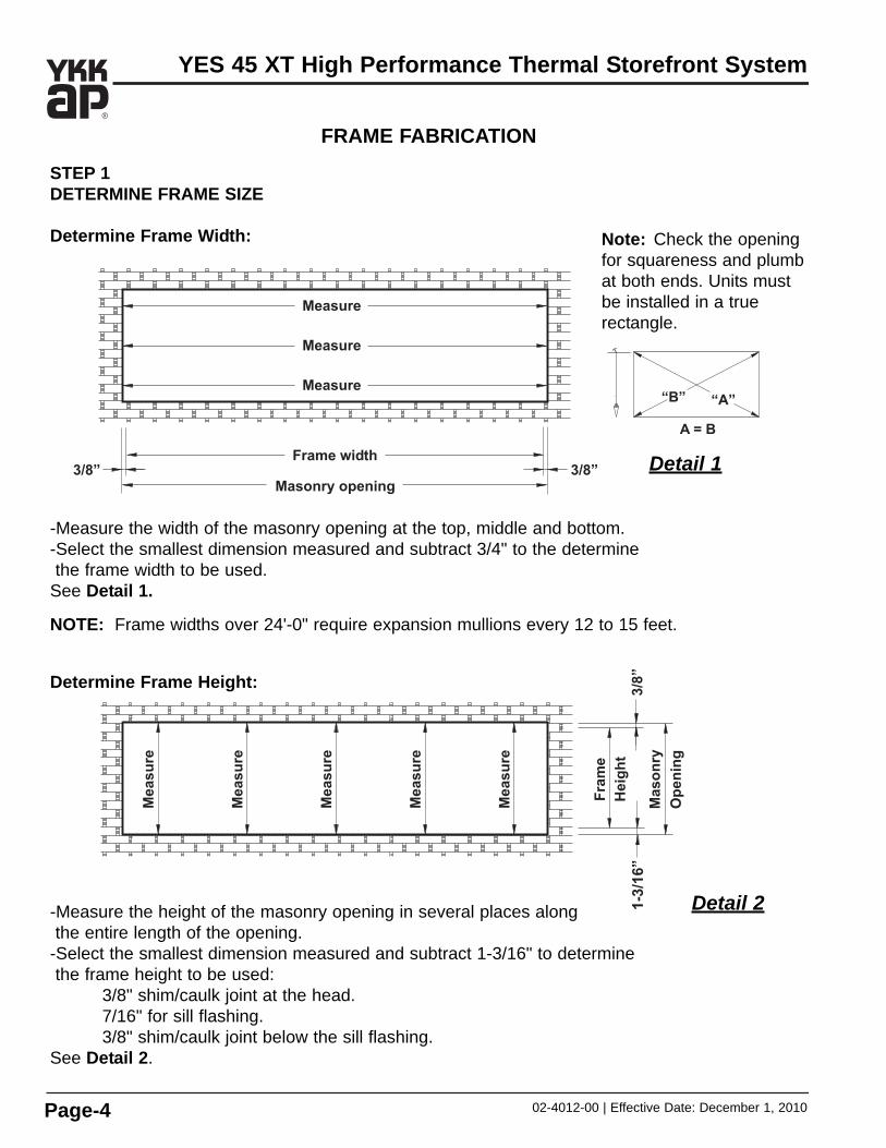
STEP 1DETERMINE FRAME SIZE
Determine Frame Width:
-Measure the width of the masonry opening at the top, middle and bottom.-Select the smallest dimension measured and subtract 3/4" to the determinethe frame width to be used.
See Detail 1.
NOTE: Frame widths over 24'-0" require expansion mullions every 12 to 15 feet.
Determine Frame Height:
-Measure the height of the masonry opening in several places alongthe entire length of the opening.
-Select the smallest dimension measured and subtract 1-3/16" to determinethe frame height to be used:
3/8" shim/caulk joint at the head.7/16" for sill flashing.3/8" shim/caulk joint below the sill flashing.
See Detail 2.
Detail 2
Note: Check the openingfor squareness and plumbat both ends. Units mustbe installed in a true rectangle.
Detail 1

Effective Date: December 1, 2010 | 02-4012-00 Page-5
YES 45 XT High Performance Thermal Storefront System
STEP 2FABRICATE TWO PIECE VERTICALS
-Cut the two piece vertical and jamb members to the frame height determined in Step 1.-Fabricate holes in vertical members for screw spline attachment using one of the methods below:
1. Using a short piece of each horizontal member as a template, center the template on the face of the vertical and mark the location of each screw spline.Drill a 0.236" diameter (#B drill bit) hole at each location marked.
2. Layout the hole locations as shown in Detail 3 and drill a 0.236" dia. (#B drill bit) clearance hole at each location marked.
3. Use the YKK AP drill fixture, H-7201, to drill the holes.4. Use punch press with appropriate die set.
See Detail 3.
FRAME FABRICATION
Detail 3Outside Glazed Inside Glazed
02-4012-00 | Effective Date: December 1, 2010Page-6
YES 45 XT High Performance Thermal Storefront System
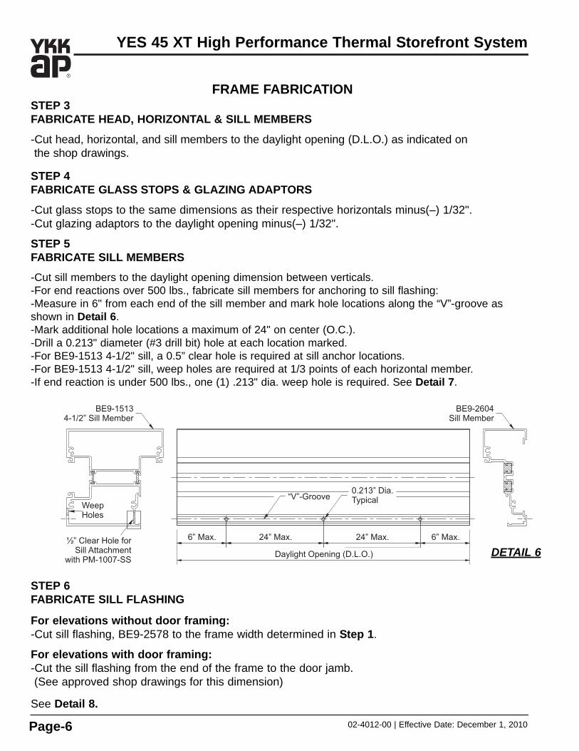
STEP 3FABRICATE HEAD, HORIZONTAL & SILL MEMBERS
-Cut head, horizontal, and sill members to the daylight opening (D.L.O.) as indicated on the shop drawings.
STEP 4FABRICATE GLASS STOPS & GLAZING ADAPTORS
-Cut glass stops to the same dimensions as their respective horizontals minus(–) 1/32".-Cut glazing adaptors to the daylight opening minus(–) 1/32".
STEP 5 FABRICATE SILL MEMBERS
-Cut sill members to the daylight opening dimension between verticals.-For end reactions over 500 lbs., fabricate sill members for anchoring to sill flashing:-Measure in 6" from each end of the sill member and mark hole locations along the “V”-groove asshown in Detail 6. -Mark additional hole locations a maximum of 24" on center (O.C.).-Drill a 0.213" diameter (#3 drill bit) hole at each location marked.-For BE9-1513 4-1/2" sill, a 0.5” clear hole is required at sill anchor locations.-For BE9-1513 4-1/2" sill, weep holes are required at 1/3 points of each horizontal member.-If end reaction is under 500 lbs., one (1) .213" dia. weep hole is required. See Detail 7.
FRAME FABRICATION
STEP 6FABRICATE SILL FLASHING
For elevations without door framing:-Cut sill flashing, BE9-2578 to the frame width determined in Step 1.
For elevations with door framing:-Cut the sill flashing from the end of the frame to the door jamb. (See approved shop drawings for this dimension)
See Detail 8.
DETAIL 6
Effective Date: December 1, 2010 | 02-4012-00 Page-7
YES 45 XT High Performance Thermal Storefront System
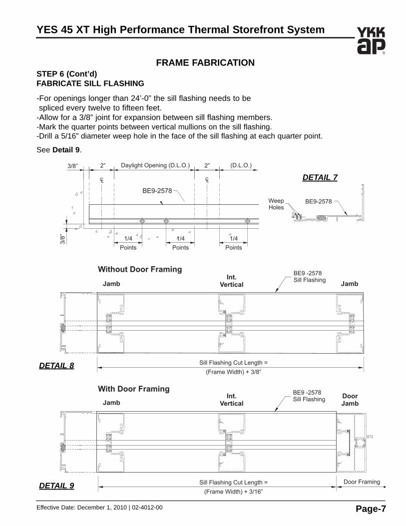
FRAME FABRICATIONSTEP 6 (Cont’d)FABRICATE SILL FLASHING
-For openings longer than 24’-0” the sill flashing needs to be spliced every twelve to fifteen feet.
-Allow for a 3/8” joint for expansion between sill flashing members.-Mark the quarter points between vertical mullions on the sill flashing.-Drill a 5/16” diameter weep hole in the face of the sill flashing at each quarter point.
See Detail 9.
DETAIL 8
DETAIL 7
DETAIL 9

02-4012-00 | Effective Date: December 1, 2010Page-8
YES 45 XT High Performance Thermal Storefront System
FRAME ASSEMBLY
STEP 7ASSEMBLE FRAMES
Screw Spline Assembly:
-Clean all joint surfaces using cleaner approved by sealant manufacturer.-Apply (butter) sealant to both ends of head, horizontal and sill members just prior to assembly.-Attach head, horizontal and sill members to vertical members with two (2) PC-1216 fastenersat each end.
-Tool the sealant into the joints and wipe away any excess sealant.See Detail 10 .
DETAIL 10
Apply sealant tothe shaded areas
at each end.
CAUTION: Always assemble frames such that each lite of glass will have a minimum of one deep vertical glazing pocket.

Effective Date: December 1, 2010 | 02-4012-00 Page-9
YES 45 XT High Performance Thermal Storefront System
STEP 8INSTALL SILL FLASHING END DAMS
-Hold the end dam with one hand and grab the tab with a pair of pliers.
-Bend the end dam left or right 90 degrees in the proper direction.
See Detail 11.
Note: The dam must be bent in the correct position for theleft or right end of the sill flashing.
-Clean all joint surfaces using cleaner approved by sealant manufacturer.
-Apply silicone sealant to the end dam as shown in Detail 12.-Slide the tab into the top portion of the sill flashing.-Tap the tab into place with a small tool until the end dam is snug against the end cut of the flashing.
-Fasten the end dam to the sill flashing with two PC-1210 screws, starting at the back, followed by the front as shown in Detail 13.
-Tool sealant along the joint between the end dam and the sill flashing as shown in Detail 14.
-Seal over any exposed screw threads.
FRAME INSTALLATION
Detail 11
Sealant
Detail 12
PC-1210
Sealant
Detail 13Detail 14

02-4012-00 | Effective Date: December 1, 2010Page-10
YES 45 XT High Performance Thermal Storefront System
STEP 9INSTALL SILL FLASHING
-Starting at the smallest opening height, install the sill flashing with a minimum of 3/8” shim underneath. Sill flashing must be installed level.
-Anchor the sill flashing to the structure a maximum of 4” from each end and then 18” to 24” on center.
-Apply and tool sealant to cover the heads of all fasteners.
STEP 10INSTALL SILL FLASHING SPLICE SLEEVE
-Remove the nub with a chisel or needle nose pliers a minimum length of 1 1/2” as shown in Detail 15 .
-After the sill flashing has been shimmed and installed to the building structure, apply a small backer rod under the sill flashing as shown in Detail 16.
-Position the Silicone Splice Sleeve against the back wall below the groove.
-Bend the Silicone Splice Sleeve into the front on the channel as shown. Mark, and cut the sleeve at this position.
-Clean Sill Flashing and Silicone Splice Sleeve with iso-propyl alcohol at the splice location
-Seal the flashing at the splice location as shown in Detail 17, before positioning the flashing. Set the Silicone Splice Sleeve into the sealant.
-Tool sealant tight as shown in Detail 17, squeezing the sheet flat.
-Thoroughly seal the small joint directly in front of theSilicone Splice Sleeve as shown in Detail 17.
FRAME INSTALLATION
1-1/2”
E2-0070Splice Sleeve(Trim to Fit)
Sealant
Detail 15
Sealant
Backer Rod Length
E2-0070Splice Sleeve
Detail 16
When using E2-0070 spilce sleeve, a compatible Silicone Sealant must be used at the splice. CompatibleSilicone Sealants include Tremco®
Spectrum 2 and Dow Corning® 795.

Effective Date: December 1, 2010 | 02-4012-00 Page-11
YES 45 XT High Performance Thermal Storefront System
STEP 11SILL FABRICATION
At every splice condition, apply bond breaker tape to the back of the sill member before the joint issealed between the sill and sill flashing.See Detail 18.
FRAME INSTALLATION
Detail 17
Detail 18

02-4012-00 | Effective Date: December 1, 2010Page-12
YES 45 XT High Performance Thermal Storefront System
FRAME INSTALLATION
Detail 19
Detail 20
-For end load reactions over 500 lbs., attach the sill to the sill flashing using PM-1008-SS screws.*
-Additionally, add one (1) PM-1008-SS fastener 2” in both directions from the centerline of the splice.
See Detail 20.
*To determine end load reactions, consult YKK AP DirecTech or refer to approved shop drawings
STEP 12INSTALL FRAMES
-Snap in flat fillers, E1-2601, or PVC flat fillerE3-0023 at head, jamb, and sill anchor locations.
-Snap assembled frames together if using screw spline assembly.
-Apply sealant continuously to the front of the back leg of the sill flashing and immediately set the frame into the opening.
See Detail 19.
-Shim jamb and head members with a minimum of 3/8” shim.
-Anchor the frame to the structure at the sill*,head, and jamb: 3” from the ends and then 18” to 24” on center.
-Always install a shim at all anchor locations.-Seal all screw heads.
Note: Use only flat head fasteners at headand jamb conditions.

Effective Date: December 1, 2010 | 02-4012-00 Page-13
YES 45 XT High Performance Thermal Storefront System
Detail 21
FRAME INSTALLATION
STEP 12 (Continued)INSTALL FRAMES
Prior to snapping the assembled frames intothe door jamb, the end of the sill flashing needsto be sealed to the door jamb.
-Apply and tool sealant to all sill flashing todoor jamb joints.
-Apply a liberal amount of sealant to completelyfill the door jamb cavity and ramp the sealant down onto the sill flashing.
See Detail 21.
Refer to the Swing Door Installation Manualfor door installation instructions.
STEP 13APPLY PERIMETER SEALANT
-Install backer rod around the perimeterof the frame.
-Apply a high grade of perimeter sealant to the joint between the frame and the structure.
-Do not seal the joint between the sill and thesill flashing.
-Make sure all screw heads are sealed.See Detail 22.
Detail 22

02-4012-00 | Effective Date: December 1, 2010Page-14
YES 45 XT High Performance Thermal Storefront System
FRAME INSTALLATION
Detail 23
-Apply and tool sealant along the edges of the water deflector and down onto the horizontal.
See Detail 24.
-Seal the ramp of the water deflector to the sides of the vertical gasket reglets.See Detail 25.
STEP 14INSTALL WATER DEFLECTORS
YES 45 XT requires the installation of a water deflector, E2-0047, at the ends of every intermediate horizontal to keep water off of the insulated units.
-Peel away the protective paper from the bottom ofthe water deflector, E2-0047, and install the waterdeflector by rotating it over each end of the horizontal.
-Position the vertical leg of the water deflector againstthe end of the horizontal.
Note: For best adhesion, make sure that the horizontal is clean and dry.
See Detail 23.
Detail 24 Detail 25

Effective Date: December 1, 2010 | 02-4012-00 Page-15
YES 45 XT High Performance Thermal Storefront System
FRAME INSTALLATION
STEP 16 (Optional)INSTALL GLAZING ADAPTORS
Glazing adaptors E9-1040, allows for glazinginfills of 1/4” or 1”. Please refer to the glazingtables above for adaptor/gasket combinations.
-Snap glazing adaptors into the interior gasket reglets of the verticals.
-Snap glazing adaptors into the interior gasket reglets of the horizontals.
-Apply and tool sealant to the joint betweenvertical and horizontal glazing adaptors.
See Detail 27.Detail 27
STEP 15APPLY INTERNAL SEALANT
-Apply a generous amount of sealant to the vertical intersection of the horizontal and vertical members.
-Tool all of the sealant to ensure a water tight joint.
-Make sure all exposed screw heads are sealed.See Detail 26.
Detail 26

02-4012-00 | Effective Date: December 1, 2010Page-16
YES 45 XT High Performance Thermal Storefront System
GLAZING
Install horizontal glazing gaskets next:-Cut horizontal glazing gaskets to Daylight Opening plus(+) 3/16” for each foot of length.-Apply sealant to each end of the horizontal glazing gasket prior to inserting into the reglet.-Insert the gasket into the reglet at each end first and push each end tight against the vertical gasket.
-Then insert the gasket at the midpoint of the opening and push the gasket into the reglet starting at the midpoint and work towards each end.
-Tool the excess sealant at the gasket corners to ensure a watertight seal.See Detail 28.
Detail 28
STEP 17INSTALL INTERIOR GLAZING GASKETS
The interior glazing gaskets must be installed prior to the glazing process.
-Using a small brush clean out any dirt that may have accumulated in the gasket reglets.
Vertical glazing gaskets must be installed first:-Cut vertical glazing gaskets to Daylight Opening plus(+) 3/16” for each foot of length.-Insert the gasket into the reglet at each end first, and then insert the gasket at the midpoint of the opening.
-Push the gasket into the reglet starting at the midpoint and work towards each end.

Effective Date: December 1, 2010 | 02-4012-00 Page-17
YES 45 XT High Performance Thermal Storefront System
GLAZINGSTEP 18INSTALL GLASS
Determine the glass size:
Horizontal Glass Size = D.L.O. plus(+) 3/4”Vertical Glass Size = D.L.O. plus(+) 3/4”
-Carefully install the glass into the opening: bring the lite up and into the deep pocket first and then rotate the other end in place.
-Carefully lift lite of glass, install setting blocks at quarter points of horizontal D.L.O. or according to engineering calculations.
-Make sure the glass is engaged with all setting blocks.
See Detail 29.
Detail 29Outside Glazed Shown
Inside Glazed Similar

02-4012-00 | Effective Date: December 1, 2010Page-18
YES 45 XT High Performance Thermal Storefront System
STEP 20 INSTALL EXTERIOR GLASS STOPS& GLAZING GASKETS
-Snap the exterior glass stops into place as shown in Detail 31.
-Install the exterior glazing gaskets using the same technique described in Step 17 on Page-16. Always install the vertical glazing gasket first.
Repeat Steps 18 through 20 until all lites are installed.Detail 31
Detail 30
GLAZINGSTEP 19 INSTALL ANTI-WALK BLOCKS
YES 45 FI frames require the installation of an anti-walk block, E2-0153, in the vertical deep glazing pocket of each lite centered along the daylight opening.
-Flatten the anti-walk block against the exterior surface of the glass and push it into the opening between the glass and the mullion until it is released into the glazing pocket.
See Detail 30.

YKK AP America Inc.7680 The BluffsSuite 100Austell, Georgia 30168www.ykkap.com


![StoreFront 3 - Citrix Docs · If the Citrix SCOM Management Pack Agent service is installed on the StoreFront server, StoreFront cannot upgrade. [#DNA-34792] On upgrade, StoreFront](https://static.fdocuments.us/doc/165x107/60ea15540160bf6e9274e47a/storefront-3-citrix-docs-if-the-citrix-scom-management-pack-agent-service-is-installed.jpg)